EP2394595A1 - Manipulation instrument - Google Patents
Manipulation instrument Download PDFInfo
- Publication number
- EP2394595A1 EP2394595A1 EP10738427A EP10738427A EP2394595A1 EP 2394595 A1 EP2394595 A1 EP 2394595A1 EP 10738427 A EP10738427 A EP 10738427A EP 10738427 A EP10738427 A EP 10738427A EP 2394595 A1 EP2394595 A1 EP 2394595A1
- Authority
- EP
- European Patent Office
- Prior art keywords
- wire
- diameter
- treatment
- treatment instrument
- small
- Prior art date
- Legal status (The legal status is an assumption and is not a legal conclusion. Google has not performed a legal analysis and makes no representation as to the accuracy of the status listed.)
- Withdrawn
Links
Images





Classifications
-
- A—HUMAN NECESSITIES
- A61—MEDICAL OR VETERINARY SCIENCE; HYGIENE
- A61B—DIAGNOSIS; SURGERY; IDENTIFICATION
- A61B17/00—Surgical instruments, devices or methods
- A61B17/32—Surgical cutting instruments
- A61B17/3205—Excision instruments
- A61B17/32056—Surgical snare instruments
-
- A—HUMAN NECESSITIES
- A61—MEDICAL OR VETERINARY SCIENCE; HYGIENE
- A61B—DIAGNOSIS; SURGERY; IDENTIFICATION
- A61B18/00—Surgical instruments, devices or methods for transferring non-mechanical forms of energy to or from the body
- A61B18/04—Surgical instruments, devices or methods for transferring non-mechanical forms of energy to or from the body by heating
- A61B18/12—Surgical instruments, devices or methods for transferring non-mechanical forms of energy to or from the body by heating by passing a current through the tissue to be heated, e.g. high-frequency current
- A61B18/14—Probes or electrodes therefor
- A61B18/1492—Probes or electrodes therefor having a flexible, catheter-like structure, e.g. for heart ablation
-
- A—HUMAN NECESSITIES
- A61—MEDICAL OR VETERINARY SCIENCE; HYGIENE
- A61B—DIAGNOSIS; SURGERY; IDENTIFICATION
- A61B18/00—Surgical instruments, devices or methods for transferring non-mechanical forms of energy to or from the body
- A61B2018/00053—Mechanical features of the instrument of device
- A61B2018/00214—Expandable means emitting energy, e.g. by elements carried thereon
-
- A—HUMAN NECESSITIES
- A61—MEDICAL OR VETERINARY SCIENCE; HYGIENE
- A61B—DIAGNOSIS; SURGERY; IDENTIFICATION
- A61B18/00—Surgical instruments, devices or methods for transferring non-mechanical forms of energy to or from the body
- A61B18/04—Surgical instruments, devices or methods for transferring non-mechanical forms of energy to or from the body by heating
- A61B18/12—Surgical instruments, devices or methods for transferring non-mechanical forms of energy to or from the body by heating by passing a current through the tissue to be heated, e.g. high-frequency current
- A61B18/14—Probes or electrodes therefor
- A61B2018/1405—Electrodes having a specific shape
- A61B2018/1407—Loop
-
- A—HUMAN NECESSITIES
- A61—MEDICAL OR VETERINARY SCIENCE; HYGIENE
- A61B—DIAGNOSIS; SURGERY; IDENTIFICATION
- A61B18/00—Surgical instruments, devices or methods for transferring non-mechanical forms of energy to or from the body
- A61B18/04—Surgical instruments, devices or methods for transferring non-mechanical forms of energy to or from the body by heating
- A61B18/12—Surgical instruments, devices or methods for transferring non-mechanical forms of energy to or from the body by heating by passing a current through the tissue to be heated, e.g. high-frequency current
- A61B18/14—Probes or electrodes therefor
- A61B2018/1405—Electrodes having a specific shape
- A61B2018/1407—Loop
- A61B2018/141—Snare
Definitions
- the present invention relates to a treatment instrument for treating body tissue.
- This application claims priority on Japanese Patent Application No. 2009-026583 filed on February 6, 2009 , the content of which is incorporated herein by reference.
- treatment instruments for conducting treatment of body tissue there are known to be lithotriptic baskets that tightly bind and crush calculi with wire, and high-frequency treatment instruments that grasp body tissue and that perform cautery incisions and the like with wire capable of carrying high-frequency current.
- the endoscopic treatment instrument described in Patent Document 1 which is provided with a wire capable of carrying high-frequency current.
- This endoscopic treatment instrument is provided with a manipulation wire that passes through a sheath, a connecting pipe that is provided on the distal end side of this manipulation wire, and a loop wire (wire) of which both ends are inserted into and fixed to this connecting pipe.
- a loop wire wire
- the present invention was made in light of the foregoing circumstances, and its object is to provide a treatment instrument that enables reduced diameter.
- the treatment instrument of the present invention is provided with: a flexible wire that has a first end part and a second end part, and that has a treatment part at an intermediate part for conducting treatment within a body cavity; small-diameter parts where at least a portion of the outer circumferential face of the wire has a smaller diameter or is denuded relative to the rest; a bundled part where the wire is bundled so as to at least include the small-diameter parts; and a manipulation wire that is connected to the bundled part.
- a small-diameter part of the wire has a portion where the diameter is smaller than that of the other portion of the wire. Accordingly, the bundled part where the wire is bundled so as to include the small-diameter parts is more compact than in the case where the same number of wires is bundled without inclusion of small-diameter parts. Accordingly, it is possible to reduce the maximum external diameter of the connecting part of the bundled part and the manipulation wire, and create a treatment instrument of smaller diameter.
- the small-diameter parts be provided at least at the first end part or the second end part.
- the small-diameter parts are provided at the end parts, it is possible to impart a larger diameter than the small-diameter parts to the intermediate part that serves to conduct treatment within the body cavity.
- the treatment instrument of the present invention has a connecting tube into which at least the small-diameter parts and the manipulation wire are inserted, and in which they are fixed.
- the respective external faces of the small-diameter parts and the manipulation wire are supported on the inner circumferential face of the connecting tube. Accordingly, fixation can be conducted simply and reliably compared to the case where the respective end parts of the small-diameter parts and the manipulation wire are joined together.
- the treatment instrument of the present invention is provided with: a flexible wire that has a first end part and a second end part, and that has a treatment part at an intermediate part for conducting treatment within a body cavity; a small-diameter part where at least a portion of the outer circumferential face of the first end part has a smaller diameter or is denuded relative to the outer circumferential face of the intermediate part of the wire; and a bundled part where the wire is curved or folded back, and the small-diameter part is fixed to the outer circumferential face of the wire.
- the length from the treatment part to the second end part is longer than the length from the treatment part to the first end part.
- the small-diameter part is bundled and fixed to the outer circumferential face of the wire, it is possible to reduce its maximum external diameter compared to the case where a conventional first end part that is not of small diameter is fixed to the outer circumferential face of the wire.
- the small-diameter parts prefferably be tapered so that diameter narrows in a tapered form.
- the external diameter of the wire in the tapered portion gradually changes, a bump in the outer circumferential face of the wire is eliminated. Consequently, it is possible to prevent damage resulting from wire breakage or the like due to catching of this bump on an object or the like.
- the wire has electrical conductivity, and that it be further provided with conductive members that are electrically connected to the aforementioned wire and that serve to supply high-frequency current. In this case, it is possible to conduct high-frequency current from the conductive members via the wire to a target object that contacts the wire.
- the manipulation wire has electrical conductivity.
- the configuration can be simplified in this case, because it is possible to conduct high-frequency current to the wire and to manipulate the wire by means of the manipulation wire.
- the treatment part be a snare wire that tightly binds body tissue and performs cautery cutting.
- the small-diameter part has a smaller diameter relative to the snare loop part in the snare wire that contacts body tissue in order to tightly bind the body tissue. Accordingly, it is possible to reduce the diameter of the bundled part regardless of the thickness of the snare loop part.
- the treatment instrument of the present invention prefferably has a plurality of the wires, and for the treatment part to be provided with a basket that contacts the body tissue at three or more separate points relative to a substance within the body cavity, and that captures the substance within the body cavity.
- small-diameter parts are provided at portions of the wires. Consequently, it is possible to reduce maximum external diameter of a bundled part where the wires are bundled so as to include more than one small-diameter part. Thereby it becomes to reduce the diameter of the treatment instrument provided with the wires.
- FIG. 1 is a plan view which shows a treatment instrument 1 of the present embodiment.
- the treatment instrument 1 is provided with a treatment part 3 that conducts treatment within a body cavity, a manipulation part 4 that is disposed at the side near the operator and that serves to manipulate the treatment part 3, and a tubular sheath 2 that is disposed between the treatment part 3 and the manipulation part 4.
- a manipulation wire 5 that is composed of flexible metallic wire and that is respectively connected to the treatment part 3 and manipulation part 4 runs through the interior of the sheath 2.
- a manipulation part provided with a manipulation body 45 into which the manipulation wire 5 is inserted so as to be capable of freely moving forward or backward and which extends in the axial direction, a slider 41 that is capable of freely moving forward or backward relative to the manipulation body 45 and that serves to conduct forward/backward operation of the manipulation wire 5 relative to the sheath 2, and a supply electrode 46 that is provided in this slider 41 and that serves to connect the manipulation wire 5 to an external high-frequency power supply device (not illustrated in the drawings).
- High-frequency current can be carried from the high-frequency power supply device to the supply electrode 46, manipulation wire 5, and a wire 50 which are conductive members that have electrical conductivity.
- the supply electrode 46, manipulation wire 5, and a wire 50 which are conductive members that have electrical conductivity.
- finger grips 42, 43, and 44 that may be gripped by the fingers of the operator.
- Fig. 2 is a plan view which shows a partial cross-section of the treatment part 3.
- the treatment part 3 of the present embodiment is a snare wire consisting of a wire 50.
- a first end part 51 and a second end part 52 are adjacently disposed with the same orientation and are inserted into a connecting tube 54.
- the wire 50 constitutes a snare loop of closed annular shape.
- the first end part 51 and second end part 52 respectively have small-diameter parts 51a and 52a that are configured with a smaller diameter than an intermediate part 53.
- a bundled part 55 where the wire 50 is bundled is configured by the first end part 51, second end part 52, and connecting tube 54.
- a distal end 5b of the manipulation wire 5 inserts into the connecting tube 54 so as to face the first end part 51 and second end part 52.
- the wire 50 and manipulation wire 5 are both inserted into the connecting tube 54, and are fixed thereto by, for example, brazing.
- an appropriate method other than brazing may be adopted such as welding, soldering, or caulking.
- Fig. 3 is a plan view which shows the wire 50.
- the wire 50 is a single wire that is composed of metal and that has a first end part 51 and second end part 52.
- the first end part 51 and second end part 52 have small-diameter parts 51a and 52a by forming tapered parts where the diameter narrows in a tapered manner.
- the method of formation of the small-diameter parts 51a and 52a one may adopt a method where the outer circumferential face of the wire is pared away by centerless taper processing, a method where the end parts of the wire 50 are immersed in a chemical solution to corrode the end parts of the wire 50, and so on.
- the user inserts a prescribed endoscope into a body cavity of a patient from a natural orifice such as the anus or mouth.
- the endoscope is provided with a guide means capable of guiding the treatment instrument 1 along the endoscope, such as a treatment instrument channel through which the treatment instrument 1 is capable of freely passing with forward or backward movement, and an imaging mechanism capable of imaging the body tissue that is the object of treatment, such as a solid-state imaging device or a fiberscope.
- the user guides the distal end of the endoscope to a prescribed position within the body cavity of the patient, and confirms the body tissue that is the object of treatment within the visual field of the imaging mechanism.
- the user passes the treatment instrument 1 along, for example, the aforementioned treatment instrument channel, and directs it to the interior of the body cavity of the patient through the treatment instrument channel.
- Fig. 4 is a side view which shows one process during use of the treatment instrument 1 in a partial cross-section, in a state where the treatment instrument 1 has been guided to the interior of the body cavity.
- the user inserts the treatment instrument 1 into the body cavity from the distal end 2a side of the sheath 2.
- the user guides the distal end 2a of the sheath 2 to the vicinity of, for example, a polyp P which is the body tissue that is the object of treatment.
- the user causes sliding movement of the slider 41 of the manipulation part 4 (see Fig. 1 ) relative to the manipulation body 45, and causes pushing movement of the manipulation wire 5 toward the distal end 2a side of the sheath 2, whereupon the wire 50 of the manipulation part 4 that is fixed to the distal end of the manipulation wire 5 projects from the distal end 2a of the sheath 2.
- the wire 50 that projects from the distal end 2a of the sheath 2 restores itself to an open state due to its own elasticity, and becomes approximately annular in shape.
- the user adjusts the position of the wire 50 so that the wire 50 is placed around the polyp P.
- Fig. 5 is a side view which shows one process where the polyp P is treated with the wire 50 in a partial cross-section.
- the user causes sliding movement of the slider 41 of the manipulation part 4 (see Fig. 1 ) in the reverse of what was described above, toward the base end side (finger grip 44 side) of the manipulation body 45, and the manipulation wire 5 is pulled toward the manipulation part 4 side.
- the wire 50 and the connecting tube 54 that are fixed to the distal end of the manipulation wire 5 are moved so as to be stored within a lumen 21 of the sheath 2.
- the wire 50 contacts the outer face of the polyp P.
- the polyp P contacts the distal end 2a of the sheath 2. In this state, the polyp P is tightly bind by both the wire 50 and the sheath 2.
- the user causes high-frequency current to be conducted to the treatment part 3 through the supply electrode 46.
- the high-frequency current is conducted to the supply electrode 46, manipulation wire 5, and wire 50 which are conductive members having electrical conductivity. A description is omitted with respect to other conductive members that serve to electrically connect the respective supply electrode 46, manipulation wire 5, and wire 50.
- a bundled part 55 is configured by bundling and inserting the first end part 51 and second end part 52 which are small-diameter parts into the interior of the connecting tube 54.
- the total diameter of the first end part 51 and second end part 52 is configured to be more than two times smaller than the diameter of the intermediate part 53. Consequently, the inner diameter of the connecting tube is smaller than the inner diameter of a conventional connecting tube. As a result, even in the case where the thickness of the tube wall of the connecting tube is made the same in order to ensure the strength of the connecting tube, the external diameter of the connecting tube is reduced.
- the treatment instrument 1 of the present embodiment it is possible to optimally conduct forward/backward operation of the treatment part 3 and the manipulation wire 5 within the sheath 2, because the sliding resistance between the lumen 21 and the connecting tube 54 can be reduced in comparison to conventional configurations. Moreover, it is also possible to compact the interstice of the lumen 21 and connecting tube 54, and further reduce the diameter of the sheath 2.
- the intermediate part 53 has a larger diameter than the small-diameter parts 51a and 52a. This is because it is necessary to have a thickness that suitably inhibits the wire 50 from excessively cutting into body tissue or the like and severing the body tissue when the intermediate part 53 tightly binds the body tissue.
- the small-diameter parts 51a and 52a are provided so as to avoid the region where contact is made with body tissue when the body tissue is tightly bind. Accordingly, body tissue such as the polyp P can be cut while cauterizing by applying high-frequency current. Consequently, the wire 50 of the present embodiment is able to combine the performance of a snare wire and reduced sheath diameter in the manner described above.
- FIG. 6A is a side view of the wire 250
- Fig. 6B is a frontal view of the wire 250
- Fig. 6C is a sectional view which shows the configuration of the wire 250 after deployment.
- Fig. 6D is a sectional view which shows another configuration of the wire 250 after deployment.
- the wire 250 has a first end part 251 and a second end part 252.
- the first end part 251 and second end part 252 respectively have small-diameter parts 251a and 252a that are formed by partially denuding the external circumferential face of the wire 250.
- the wire 250 has a bundled part 255 that is formed by inserting both the first end part 251 and second end part 252 into the connecting tube 54, and fixing them to the connecting tube 54.
- Maximum outer diameter when the first end part 251 and second end part 252 are brought together at this time is approximately equal to the outer diameter of the manipulation wire 5.
- the element that regulates the inner diameter of the connecting tube 54 is the outer diameter of the manipulation wire 5. Accordingly, with respect to the present variation, it is possible to establish the inner diameter of the connecting tube 54 at the minimum inner diameter that satisfies the form that is required by the manipulation wire 5 when the treatment part 3 is moved forward or backward. Consequently, the present variation enables minimization of the inner diameter and external diameter of the connecting tube 54. Accordingly, the present variation enables the diameter of the sheath to be reduced like the treatment instrument 1 described above.
- FIG. 7A is a side view of the wire 350
- Fig. 7B is a frontal view of the wire 350
- Fig. 7C is a sectional view which shows the configuration of the wire 350 after deployment.
- the wire 350 of the present variation has a first end part 351 and a second end part 352.
- the first end part 351 and second end part 352 respectively have small-diameter parts 351a and 352a which are denuded to a prescribed diameter only and reduced diameter relative to an intermediate part 353.
- the wire 350 has a bundled part 355 formed by inserting both the first end part 351 and second end part 352 into the connecting tube 54, and fixing them to the connecting tube 54.
- Maximum outer diameter when the first end part 351 and second end part 352 are brought together at this time is approximately equal to the outer diameter of the manipulation wire 5.
- the diameter of the bundled part can be reduced in the manner described above even with the aforementioned shape, it is possible to obtain the same effect as the treatment instrument 1 described above.
- a treatment instrument of a second embodiment of the present invention is described with reference to Fig. 8A to Fig. 8D .
- the same reference symbols are given to items that are common to the configuration of the treatment instrument of the above-described first embodiment, and description thereof is omitted.
- the treatment instrument of the present embodiment is not provided with the manipulation wire 5, and is provided with a wire 450 instead of the wire 50.
- Fig. 8A is a side view of the wire 450. As shown in Fig. 8A , the wire 450 has a first end part 451 and a second end part 452. The first end part 451 is provided with a small-diameter part 451a that is formed like the small-diameter part 251a.
- Fig. 8B is a side view which shows the configuration of the wire 450 after deployment.
- the wire 450 folds back at an intermediate part 453.
- a bundled part 455 is formed by welding anchoring the small-diameter part 451a to a connection portion W of the outer face of the wire 450. From the connection portion W to its second end part 452, the wire 450 extends until the manipulation part 4 (see Fig. 1 ) like the manipulation wire 5 of the first embodiment, and is moved forward or backward by the slider 41.
- Fig. 8C is a side view which shows a partial cross-section of another configuration after deployment of the wire 450.
- the connection portion of the small-diameter part 451a and the outer face of the wire 450 may be inserted and be fixed to a tubular connecting tube 454. Even with this type of configuration, it is possible to obtain the effect of enabling a reduction in diameter of the sheath as in the above-described configurations.
- the manipulation wire 5 is not provided, and as the second end part 452 side of the wire 450 is connected to the manipulation part 4, the number of components can be reduced.
- Fig. 8D is a side view which shows a partial cross-section of another configuration after deployment of the wire 450.
- the bump that occurs in the small-diameter part 451a may be configured so as to face toward the outside of the snare loop created by the wire 450.
- a treatment instrument of a third embodiment of the present invention is described with reference to Fig. 9A and Fig. 9B .
- wires 550 are multiply provided in which small-diameter parts are formed similar to those of the wire 50 of the first embodiment.
- Fig. 9B is an enlarged view which shows a partial cross-section in the vicinity of a second bundled part 555.
- small-diameter parts 551a provided at the end parts of the wires 550 are inserted into and fixed to a connecting tube 554.
- the small-diameter parts 551a are configured by forming tapered parts at both ends of the wires 550.
- end parts of the wires 550 including small-diameter parts are also similarly inserted into and fixed to a first bundled part 6.
- the wires 550 are bundled in threes to form the first bundled part 6 and second bundled part 555. Accordingly, an approximately spherical space is formed by the three wires 555. That is, in the present embodiment, the treatment part that has the wires 550 bundled by the first bundled part 6 and second bundled part 555 is used as a so-called basket that captures an object such as body tissue and the like.
- This type of basket configuration may be suitably employed, for example, for lithotriptic baskets that serve to crush gallstones and the like, stone extraction baskets that serve to recover gallstones and the like, or basket-type microsnares that serve to crush blood clots and the like.
- baskets having bundled parts including one or more small-diameter parts multiple wires are bundled together, with the result that it is possible to reduce the maximum external diameter of the portions where the wires are bundled in comparison to conventional baskets where the bundled portions are of large diameter.
- wires 650 are multiply provided in which small-diameter parts are formed similar to those of the wire 250 of the first embodiment.
- the end parts of the multiple wires 650 are respectively bundled at a first bundled part 6 and a second bundled part 655.
- Fig. 10B is an enlarged view which shows a partial cross-section in the vicinity of the second bundled part 655.
- small-diameter parts 651a provided at the end parts of the wires 650 are inserted into and fixed to a connecting tube 654.
- the small-diameter parts 651a are configured by denuding a portion of the outer circumferential face at both ends of the wires 650. Although the details are not illustrated in the drawings, end parts of the wires including small-diameter parts are also similarly inserted into and fixed to the first bundled part 6.
- a basket configuration similar to that of the third embodiment is obtainable with this type of configuration as well.
- By bundling multiple wires in the same way as the third embodiment it is possible to reduce the maximum external diameter of the portions where the wires are bundled in comparison to conventional baskets where the bundled portions are of large diameter.
- wires 750 are multiply provided in which small-diameter parts are formed similar to those of the wire 350 of the first embodiment.
- the end parts of the multiple wires 750 are respectively bundled at a first bundled part 6 and a second bundled part 755.
- Fig. 11B is an enlarged view which shows a partial cross-section in the vicinity of the second bundled part 755.
- small-diameter parts 751a provided at the end parts of the wires 750 are inserted into and fixed to a connecting tube 754.
- the small-diameter parts 751a are configured by reducing the diameter of the outer circumference of both ends of the wires 750 to a prescribed diameter. Although the details are not illustrated in the drawings, end parts of the wires including small-diameter parts are also similarly inserted into and fixed to the first bundled part 6. A basket configuration similar to that of the third embodiment is obtained with this type of configuration as well. By bundling multiple wires in the same way as the third embodiment, it is possible to reduce the maximum external diameter of the portions where the wires are bundled in comparison to conventional baskets where the bundled portions are of large diameter.
- the treatment instrument of the present invention it is possible to reduce the maximum external diameter of the connecting part of the bundled part and the manipulation wire, and create a treatment instrument of smaller diameter.
Landscapes
- Health & Medical Sciences (AREA)
- Surgery (AREA)
- Life Sciences & Earth Sciences (AREA)
- Engineering & Computer Science (AREA)
- Molecular Biology (AREA)
- General Health & Medical Sciences (AREA)
- Veterinary Medicine (AREA)
- Public Health (AREA)
- Nuclear Medicine, Radiotherapy & Molecular Imaging (AREA)
- Biomedical Technology (AREA)
- Heart & Thoracic Surgery (AREA)
- Medical Informatics (AREA)
- Animal Behavior & Ethology (AREA)
- Cardiology (AREA)
- Physics & Mathematics (AREA)
- Plasma & Fusion (AREA)
- Otolaryngology (AREA)
- Surgical Instruments (AREA)
Abstract
This treatment instrument includes: a flexible wire (50) that has a first end part (51) and a second end part (52), and that has a treatment part (3) at an intermediate part (53) for conducting treatment within a body cavity; small-diameter parts (51a, 52a) where at least a portion of the outer circumferential face of the wire has a smaller diameter or is denuded relative to the rest; a bundled part (55) where the wire is bundled so as to at least include the small-diameter parts; and a manipulation wire (5) that is connected to this bundled part.
Description
- The present invention relates to a treatment instrument for treating body tissue.
This application claims priority on Japanese Patent Application No.2009-026583 filed on February 6, 2009 - Conventionally, as treatment instruments for conducting treatment of body tissue, there are known to be lithotriptic baskets that tightly bind and crush calculi with wire, and high-frequency treatment instruments that grasp body tissue and that perform cautery incisions and the like with wire capable of carrying high-frequency current.
- As examples of such treatment instruments, there is, for example, the endoscopic treatment instrument described in Patent Document 1 which is provided with a wire capable of carrying high-frequency current. This endoscopic treatment instrument is provided with a manipulation wire that passes through a sheath, a connecting pipe that is provided on the distal end side of this manipulation wire, and a loop wire (wire) of which both ends are inserted into and fixed to this connecting pipe.
According to the endoscopic treatment instrument described in Patent Document 1, it is possible to securely grasp body tissue with this loop wire (wire), and excise body tissue such as polyps and the like. -
- [Patent Document 1] Japanese Unexamined Patent Application, First Publication No.
2000-271146 - However, with the endoscopic treatment instrument described in Patent Document 1, both ends of the wire are inserted together into and fixed to the connecting pipe. Consequently, there is the problem that it is necessary to configure the inner diameter of the connecting pipe to be at least twice the outer diameter of the wire, and that it is difficult to reduce the diameter of the connecting pipe. Moreover, when the connecting pipe that bulges in the radial direction relative to the wire undergoes sliding movement relative to that sheath, sliding resistance occurs. Consequently, there is the problem that the tractive force and pressing force that are required to operate the manipulation wire are large.
- The present invention was made in light of the foregoing circumstances, and its object is to provide a treatment instrument that enables reduced diameter.
- In order to solve the aforementioned problems, the present invention is provided with the following structure.
The treatment instrument of the present invention is provided with: a flexible wire that has a first end part and a second end part, and that has a treatment part at an intermediate part for conducting treatment within a body cavity; small-diameter parts where at least a portion of the outer circumferential face of the wire has a smaller diameter or is denuded relative to the rest; a bundled part where the wire is bundled so as to at least include the small-diameter parts; and a manipulation wire that is connected to the bundled part. - According to the present invention, a small-diameter part of the wire has a portion where the diameter is smaller than that of the other portion of the wire. Accordingly, the bundled part where the wire is bundled so as to include the small-diameter parts is more compact than in the case where the same number of wires is bundled without inclusion of small-diameter parts. Accordingly, it is possible to reduce the maximum external diameter of the connecting part of the bundled part and the manipulation wire, and create a treatment instrument of smaller diameter.
- With respect to the treatment instrument of the present invention, it is preferable that the small-diameter parts be provided at least at the first end part or the second end part.
In this case, as the small-diameter parts are provided at the end parts, it is possible to impart a larger diameter than the small-diameter parts to the intermediate part that serves to conduct treatment within the body cavity. - It is also preferable that the treatment instrument of the present invention has a connecting tube into which at least the small-diameter parts and the manipulation wire are inserted, and in which they are fixed.
In this case, as the small-diameter parts and manipulation wire are together inserted into and fixed to a connecting tube, the respective external faces of the small-diameter parts and the manipulation wire are supported on the inner circumferential face of the connecting tube. Accordingly, fixation can be conducted simply and reliably compared to the case where the respective end parts of the small-diameter parts and the manipulation wire are joined together. - The treatment instrument of the present invention is provided with: a flexible wire that has a first end part and a second end part, and that has a treatment part at an intermediate part for conducting treatment within a body cavity; a small-diameter part where at least a portion of the outer circumferential face of the first end part has a smaller diameter or is denuded relative to the outer circumferential face of the intermediate part of the wire; and a bundled part where the wire is curved or folded back, and the small-diameter part is fixed to the outer circumferential face of the wire. The length from the treatment part to the second end part is longer than the length from the treatment part to the first end part.
According to the present invention, as the small-diameter part is bundled and fixed to the outer circumferential face of the wire, it is possible to reduce its maximum external diameter compared to the case where a conventional first end part that is not of small diameter is fixed to the outer circumferential face of the wire. - With respect to the treatment instrument of the present invention, it is also acceptable for the small-diameter parts to be tapered so that diameter narrows in a tapered form.
In this case, as the external diameter of the wire in the tapered portion gradually changes, a bump in the outer circumferential face of the wire is eliminated. Consequently, it is possible to prevent damage resulting from wire breakage or the like due to catching of this bump on an object or the like. - In addition, with respect to the treatment instrument of the present invention, it is preferable that the wire has electrical conductivity, and that it be further provided with conductive members that are electrically connected to the aforementioned wire and that serve to supply high-frequency current.
In this case, it is possible to conduct high-frequency current from the conductive members via the wire to a target object that contacts the wire. - Moreover, with respect to the treatment instrument of the present invention, it is preferable that the manipulation wire has electrical conductivity.
The configuration can be simplified in this case, because it is possible to conduct high-frequency current to the wire and to manipulate the wire by means of the manipulation wire. - With respect to the treatment instrument of the present invention, it is also preferable that the treatment part be a snare wire that tightly binds body tissue and performs cautery cutting.
In this case, the small-diameter part has a smaller diameter relative to the snare loop part in the snare wire that contacts body tissue in order to tightly bind the body tissue. Accordingly, it is possible to reduce the diameter of the bundled part regardless of the thickness of the snare loop part. - It is also acceptable for the treatment instrument of the present invention to have a plurality of the wires, and for the treatment part to be provided with a basket that contacts the body tissue at three or more separate points relative to a substance within the body cavity, and that captures the substance within the body cavity.
- According to the treatment instrument of the present invention, small-diameter parts are provided at portions of the wires. Consequently, it is possible to reduce maximum external diameter of a bundled part where the wires are bundled so as to include more than one small-diameter part. Thereby it becomes to reduce the diameter of the treatment instrument provided with the wires.
-
-
Fig. 1 is a plan view which shows a treatment instrument of a first embodiment of the present invention. -
Fig. 2 is a plan view which shows a treatment part of the same treatment instrument. -
Fig. 3 is a plan view which shows a wire of the same treatment instrument. -
Fig. 4 is a side view which shows operations during use of the same treatment instrument in a partial cross-section. -
Fig. 5 is a side view which shows operations during use of the same treatment instrument in a partial cross-section. -
Fig. 6A is a drawing which shows the configuration of a variation of the same treatment instrument. -
Fig. 6B is a drawing which shows the configuration of a variation of the same treatment instrument. -
Fig. 6C is a drawing which shows the configuration of a variation of the same treatment instrument. -
Fig. 6D is a drawing which shows the configuration of a variation of the same treatment instrument. -
Fig. 7A is a drawing which shows another variation of the same treatment instrument. -
Fig. 7B is a drawing which shows another variation of the same treatment instrument. -
Fig. 7C is a drawing which shows another variation of the same treatment instrument. -
Fig. 8A is a side view which shows a partial configuration of a treatment instrument of a second embodiment of the present invention. -
Fig. 8B is a side view which shows a partial configuration of the treatment instrument of the second embodiment of the present invention. -
Fig. 8C is a side view which shows a partial configuration of the treatment instrument of the second embodiment of the present invention. -
Fig. 8D is a side view which shows a partial configuration of the treatment instrument of the second embodiment of the present invention. -
Fig. 9A is a side view which shows a partial configuration of a treatment instrument of a third embodiment of the present invention in a partial cross-section. -
Fig. 9B is a side view which shows a partial configuration of the treatment instrument of the third embodiment of the present invention in a partial cross-section. -
Fig. 10A is a side view which shows a partial configuration of the treatment instrument of a fourth embodiment of the present invention in a partial cross-section. -
Fig. 10B is a side view which shows a partial configuration of the treatment instrument of the fourth embodiment of the present invention in a partial cross-section. -
Fig. 11A is a side view which shows a partial configuration of the treatment instrument of a fifth embodiment of the present invention in a partial cross-section. -
Fig. 11B is a side view which shows a partial configuration of the treatment instrument of the fifth embodiment of the present invention in a partial cross-section. - A treatment instrument of a first embodiment of the present invention is described below with reference to
Fig. 1 to Fig. 3 .
Fig. 1 is a plan view which shows a treatment instrument 1 of the present embodiment. As shown inFig. 1 , the treatment instrument 1 is provided with atreatment part 3 that conducts treatment within a body cavity, amanipulation part 4 that is disposed at the side near the operator and that serves to manipulate thetreatment part 3, and atubular sheath 2 that is disposed between thetreatment part 3 and themanipulation part 4.
Amanipulation wire 5 that is composed of flexible metallic wire and that is respectively connected to thetreatment part 3 andmanipulation part 4 runs through the interior of thesheath 2. - With respect to the
manipulation part 4, one may appropriately adopt a configuration of a conventional manipulation part of a treatment instrument. For example, one may adopt a manipulation part provided with amanipulation body 45 into which themanipulation wire 5 is inserted so as to be capable of freely moving forward or backward and which extends in the axial direction, aslider 41 that is capable of freely moving forward or backward relative to themanipulation body 45 and that serves to conduct forward/backward operation of themanipulation wire 5 relative to thesheath 2, and asupply electrode 46 that is provided in thisslider 41 and that serves to connect themanipulation wire 5 to an external high-frequency power supply device (not illustrated in the drawings). High-frequency current can be carried from the high-frequency power supply device to thesupply electrode 46,manipulation wire 5, and awire 50 which are conductive members that have electrical conductivity.
With respect to this type ofmanipulation part 4, in order to optimally conduct forward and backward operation of theslider 41 relative to themanipulation body 45, it is preferable to provide finger grips 42, 43, and 44 that may be gripped by the fingers of the operator. -
Fig. 2 is a plan view which shows a partial cross-section of thetreatment part 3. As shown inFig. 2 , thetreatment part 3 of the present embodiment is a snare wire consisting of awire 50. With respect to thewire 50, afirst end part 51 and asecond end part 52 are adjacently disposed with the same orientation and are inserted into a connectingtube 54. Accordingly, thewire 50 constitutes a snare loop of closed annular shape. Moreover, in the present embodiment, thefirst end part 51 andsecond end part 52 respectively have small-diameter parts intermediate part 53. - Furthermore, a bundled
part 55 where thewire 50 is bundled is configured by thefirst end part 51,second end part 52, and connectingtube 54. In addition, adistal end 5b of themanipulation wire 5 inserts into the connectingtube 54 so as to face thefirst end part 51 andsecond end part 52. - The
wire 50 andmanipulation wire 5 are both inserted into the connectingtube 54, and are fixed thereto by, for example, brazing. With respect to the method of connecting themanipulation wire 5 and thewire 50, so long as it is a method that uses the connectingtube 54, an appropriate method other than brazing may be adopted such as welding, soldering, or caulking. -
Fig. 3 is a plan view which shows thewire 50. As shown inFig. 3 , thewire 50 is a single wire that is composed of metal and that has afirst end part 51 andsecond end part 52. With respect to thiswire 50, compared to theintermediate part 53, thefirst end part 51 andsecond end part 52 have small-diameter parts - With respect to the method of formation of the small-
diameter parts wire 50 are immersed in a chemical solution to corrode the end parts of thewire 50, and so on. Moreover, although not illustrated in the drawings, it is also possible to form an inclined end face and form the taper by cutting thewire 50 at thefirst end part 51 orsecond end part 52 at an angle that is inclined relative to the axial line of thewire 50. - Operations during use of the treatment instrument 1 of the present embodiment having the configuration described above are described with reference to
Fig. 4 and Fig. 5 .
First, the user inserts a prescribed endoscope into a body cavity of a patient from a natural orifice such as the anus or mouth. In the present embodiment, the endoscope is provided with a guide means capable of guiding the treatment instrument 1 along the endoscope, such as a treatment instrument channel through which the treatment instrument 1 is capable of freely passing with forward or backward movement, and an imaging mechanism capable of imaging the body tissue that is the object of treatment, such as a solid-state imaging device or a fiberscope.
The user guides the distal end of the endoscope to a prescribed position within the body cavity of the patient, and confirms the body tissue that is the object of treatment within the visual field of the imaging mechanism. Next, the user passes the treatment instrument 1 along, for example, the aforementioned treatment instrument channel, and directs it to the interior of the body cavity of the patient through the treatment instrument channel. -
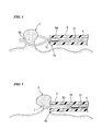
Fig. 4 is a side view which shows one process during use of the treatment instrument 1 in a partial cross-section, in a state where the treatment instrument 1 has been guided to the interior of the body cavity. As shown inFig. 4 , the user inserts the treatment instrument 1 into the body cavity from thedistal end 2a side of thesheath 2. The user then guides thedistal end 2a of thesheath 2 to the vicinity of, for example, a polyp P which is the body tissue that is the object of treatment. - Next, the user causes sliding movement of the
slider 41 of the manipulation part 4 (seeFig. 1 ) relative to themanipulation body 45, and causes pushing movement of themanipulation wire 5 toward thedistal end 2a side of thesheath 2, whereupon thewire 50 of themanipulation part 4 that is fixed to the distal end of themanipulation wire 5 projects from thedistal end 2a of thesheath 2. - The
wire 50 that projects from thedistal end 2a of thesheath 2 restores itself to an open state due to its own elasticity, and becomes approximately annular in shape. The user adjusts the position of thewire 50 so that thewire 50 is placed around the polyp P. -
Fig. 5 is a side view which shows one process where the polyp P is treated with thewire 50 in a partial cross-section. The user causes sliding movement of theslider 41 of the manipulation part 4 (seeFig. 1 ) in the reverse of what was described above, toward the base end side (finger grip 44 side) of themanipulation body 45, and themanipulation wire 5 is pulled toward themanipulation part 4 side.
When this is done, thewire 50 and the connectingtube 54 that are fixed to the distal end of themanipulation wire 5 are moved so as to be stored within alumen 21 of thesheath 2. At this time, as the polyp P is enclosed by thewire 50, thewire 50 contacts the outer face of the polyp P. Furthermore, when thewire 50 is pulled back into thelumen 21 of thesheath 2, the polyp P contacts thedistal end 2a of thesheath 2. In this state, the polyp P is tightly bind by both thewire 50 and thesheath 2. - Next, the user causes high-frequency current to be conducted to the
treatment part 3 through thesupply electrode 46. The high-frequency current is conducted to thesupply electrode 46,manipulation wire 5, andwire 50 which are conductive members having electrical conductivity. A description is omitted with respect to other conductive members that serve to electrically connect therespective supply electrode 46,manipulation wire 5, andwire 50. - At a contact portion T of the
wire 50 and the polyp P, Joule heat is generated by the high-frequency current, whereupon a cautery incision of body tissue is made at the contact portion T, and the polyp P is excised.
When the polyp P is excised, the polyp P is taken out of the body after excision using a known tissue recovery device that is not illustrated in the drawings, the treatment instrument 1 is withdrawn from the interior of the body cavity, and the treatment sequence is terminated. - With respect to conventional treatment instruments, it was required to reduce the external diameter of the sheath, but it was difficult to reduce diameter, because the maximum external diameter of the member that includes the wire, connecting tube and manipulation wire, and that moves backward and forward through the interior of the sheath is determined by the external diameter of the end part of the wire and the external diameter of the connecting tube. As a result, previously, the connecting tube would slide against the lumen of the sheath at the connecting portion of the wire and the manipulation wire, and resistance would be large when the operator manipulated the manipulation part.
- According to the treatment instrument 1 of the present embodiment, a bundled
part 55 is configured by bundling and inserting thefirst end part 51 andsecond end part 52 which are small-diameter parts into the interior of the connectingtube 54. The total diameter of thefirst end part 51 andsecond end part 52 is configured to be more than two times smaller than the diameter of theintermediate part 53. Consequently, the inner diameter of the connecting tube is smaller than the inner diameter of a conventional connecting tube. As a result, even in the case where the thickness of the tube wall of the connecting tube is made the same in order to ensure the strength of the connecting tube, the external diameter of the connecting tube is reduced. Accordingly, with respect to the treatment instrument 1 of the present embodiment, it is possible to optimally conduct forward/backward operation of thetreatment part 3 and themanipulation wire 5 within thesheath 2, because the sliding resistance between thelumen 21 and the connectingtube 54 can be reduced in comparison to conventional configurations.
Moreover, it is also possible to compact the interstice of thelumen 21 and connectingtube 54, and further reduce the diameter of thesheath 2. - In the present embodiment, the
intermediate part 53 has a larger diameter than the small-diameter parts wire 50 from excessively cutting into body tissue or the like and severing the body tissue when theintermediate part 53 tightly binds the body tissue. With respect to thewire 50 of the present embodiment, the small-diameter parts wire 50 of the present embodiment is able to combine the performance of a snare wire and reduced sheath diameter in the manner described above. - A variation of the
wire 50 is described below with reference toFig. 6A, Fig. 6B, Fig. 6C, and Fig. 6D .
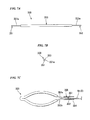
The drawings show awire 250 of the present variation.Fig. 6A is a side view of thewire 250;Fig. 6B is a frontal view of thewire 250; andFig. 6C is a sectional view which shows the configuration of thewire 250 after deployment. In addition,Fig. 6D is a sectional view which shows another configuration of thewire 250 after deployment. - As shown in
Fig. 6A and Fig. 6B , thewire 250 has afirst end part 251 and asecond end part 252. Thefirst end part 251 andsecond end part 252 respectively have small-diameter parts wire 250. - As shown in
Fig. 6C , thewire 250 has a bundledpart 255 that is formed by inserting both thefirst end part 251 andsecond end part 252 into the connectingtube 54, and fixing them to the connectingtube 54. Maximum outer diameter when thefirst end part 251 andsecond end part 252 are brought together at this time is approximately equal to the outer diameter of themanipulation wire 5. - As shown in
Fig. 6D , it is also acceptable to adopt a form that imposes a positional relation where the respective bumps that occur in the small-diameter parts wire 250 is deployed. - In the present variation, when the
first end part 251 andsecond end part 252 are inserted into the connectingtube 54, the element that regulates the inner diameter of the connectingtube 54 is the outer diameter of themanipulation wire 5. Accordingly, with respect to the present variation, it is possible to establish the inner diameter of the connectingtube 54 at the minimum inner diameter that satisfies the form that is required by themanipulation wire 5 when thetreatment part 3 is moved forward or backward. Consequently, the present variation enables minimization of the inner diameter and external diameter of the connectingtube 54. Accordingly, the present variation enables the diameter of the sheath to be reduced like the treatment instrument 1 described above. - A variation of the
wire 50 is described below with reference toFig. 7A, Fig. 7B, and Fig. 7C .
These drawings show awire 350 of the present variation.Fig. 7A is a side view of thewire 350;Fig. 7B is a frontal view of thewire 350; andFig. 7C is a sectional view which shows the configuration of thewire 350 after deployment. - As shown in
Fig. 7A and Fig. 7B , thewire 350 of the present variation has afirst end part 351 and asecond end part 352. Thefirst end part 351 andsecond end part 352 respectively have small-diameter parts intermediate part 353.
As shown inFig. 7C , thewire 350 has a bundledpart 355 formed by inserting both thefirst end part 351 andsecond end part 352 into the connectingtube 54, and fixing them to the connectingtube 54. Maximum outer diameter when thefirst end part 351 andsecond end part 352 are brought together at this time is approximately equal to the outer diameter of themanipulation wire 5.
As the diameter of the bundled part can be reduced in the manner described above even with the aforementioned shape, it is possible to obtain the same effect as the treatment instrument 1 described above. - Next, a treatment instrument of a second embodiment of the present invention is described with reference to
Fig. 8A to Fig. 8D . In each of the embodiments described below, the same reference symbols are given to items that are common to the configuration of the treatment instrument of the above-described first embodiment, and description thereof is omitted.
The treatment instrument of the present embodiment is not provided with themanipulation wire 5, and is provided with awire 450 instead of thewire 50. -
Fig. 8A is a side view of thewire 450. As shown inFig. 8A , thewire 450 has afirst end part 451 and asecond end part 452. Thefirst end part 451 is provided with a small-diameter part 451a that is formed like the small-diameter part 251a. -
Fig. 8B is a side view which shows the configuration of thewire 450 after deployment. As shown inFig. 8B , thewire 450 folds back at anintermediate part 453. Furthermore, a bundledpart 455 is formed by welding anchoring the small-diameter part 451a to a connection portion W of the outer face of thewire 450. From the connection portion W to itssecond end part 452, thewire 450 extends until the manipulation part 4 (seeFig. 1 ) like themanipulation wire 5 of the first embodiment, and is moved forward or backward by theslider 41. -
Fig. 8C is a side view which shows a partial cross-section of another configuration after deployment of thewire 450. As shown inFig. 8C , the connection portion of the small-diameter part 451a and the outer face of thewire 450 may be inserted and be fixed to atubular connecting tube 454. Even with this type of configuration, it is possible to obtain the effect of enabling a reduction in diameter of the sheath as in the above-described configurations. Moreover, as themanipulation wire 5 is not provided, and as thesecond end part 452 side of thewire 450 is connected to themanipulation part 4, the number of components can be reduced.
Fig. 8D is a side view which shows a partial cross-section of another configuration after deployment of thewire 450. As shown inFig. 8D , the bump that occurs in the small-diameter part 451a may be configured so as to face toward the outside of the snare loop created by thewire 450. - Next, a treatment instrument of a third embodiment of the present invention is described with reference to
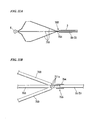
Fig. 9A and Fig. 9B . In the present embodiment,wires 550 are multiply provided in which small-diameter parts are formed similar to those of thewire 50 of the first embodiment. For example,Fig. 9B is an enlarged view which shows a partial cross-section in the vicinity of a second bundledpart 555. As shown inFig. 9B , small-diameter parts 551a provided at the end parts of thewires 550 are inserted into and fixed to a connectingtube 554. The small-diameter parts 551a are configured by forming tapered parts at both ends of thewires 550. Although not illustrated in the drawings, end parts of thewires 550 including small-diameter parts are also similarly inserted into and fixed to a first bundledpart 6. - As shown in
Fig. 9A and Fig. 9B , in the present embodiment, thewires 550 are bundled in threes to form the first bundledpart 6 and second bundledpart 555. Accordingly, an approximately spherical space is formed by the threewires 555. That is, in the present embodiment, the treatment part that has thewires 550 bundled by the first bundledpart 6 and second bundledpart 555 is used as a so-called basket that captures an object such as body tissue and the like.
This type of basket configuration may be suitably employed, for example, for lithotriptic baskets that serve to crush gallstones and the like, stone extraction baskets that serve to recover gallstones and the like, or basket-type microsnares that serve to crush blood clots and the like.
With respect to such baskets having bundled parts including one or more small-diameter parts, multiple wires are bundled together, with the result that it is possible to reduce the maximum external diameter of the portions where the wires are bundled in comparison to conventional baskets where the bundled portions are of large diameter. - Next, a treatment instrument of a fourth embodiment of the present invention is described with reference to
Fig. 10A and Fig. 10B . In the present embodiment,wires 650 are multiply provided in which small-diameter parts are formed similar to those of thewire 250 of the first embodiment. As shown inFig. 10A , the end parts of themultiple wires 650 are respectively bundled at a first bundledpart 6 and a second bundledpart 655.
For example,Fig. 10B is an enlarged view which shows a partial cross-section in the vicinity of the second bundledpart 655. As shown inFig. 10B , small-diameter parts 651a provided at the end parts of thewires 650 are inserted into and fixed to a connectingtube 654. The small-diameter parts 651a are configured by denuding a portion of the outer circumferential face at both ends of thewires 650. Although the details are not illustrated in the drawings, end parts of the wires including small-diameter parts are also similarly inserted into and fixed to the first bundledpart 6.
A basket configuration similar to that of the third embodiment is obtainable with this type of configuration as well. By bundling multiple wires in the same way as the third embodiment, it is possible to reduce the maximum external diameter of the portions where the wires are bundled in comparison to conventional baskets where the bundled portions are of large diameter.
In the present embodiment, it is also possible to adopt configurations where the orientation of the bumps that occur in the small-diameter parts are changed, in a manner similar to the positional relations shown inFig. 6C and Fig. 6D . - Next, a treatment instrument of a fifth embodiment of the present invention is described with reference to
Fig. 11A and Fig. 11B . In the present embodiment,wires 750 are multiply provided in which small-diameter parts are formed similar to those of thewire 350 of the first embodiment. As shown inFig. 11A , the end parts of themultiple wires 750 are respectively bundled at a first bundledpart 6 and a second bundledpart 755.
For example,Fig. 11B is an enlarged view which shows a partial cross-section in the vicinity of the second bundledpart 755. As shown inFig. 11B , small-diameter parts 751a provided at the end parts of thewires 750 are inserted into and fixed to a connectingtube 754. The small-diameter parts 751a are configured by reducing the diameter of the outer circumference of both ends of thewires 750 to a prescribed diameter. Although the details are not illustrated in the drawings, end parts of the wires including small-diameter parts are also similarly inserted into and fixed to the first bundledpart 6.
A basket configuration similar to that of the third embodiment is obtained with this type of configuration as well. By bundling multiple wires in the same way as the third embodiment, it is possible to reduce the maximum external diameter of the portions where the wires are bundled in comparison to conventional baskets where the bundled portions are of large diameter. - While preferred embodiments of the invention have been described and illustrated above, it should be understood that these are exemplary of the invention, and are not to be considered as limiting. Additions, omissions, substitutions, and other modifications can be made without departing from the spirit or scope of the present invention. Accordingly, the invention is not to be considered as being limited by the foregoing description, and is only limited by the scope of the appended claims.
- According to the treatment instrument of the present invention, it is possible to reduce the maximum external diameter of the connecting part of the bundled part and the manipulation wire, and create a treatment instrument of smaller diameter.
-
- 1:
- treatment instrument
- 3:
- treatment part
- 4:
- manipulation part
- 5:
- manipulation wire
- 55, 255, 455:
- bundled part
- 6:
- first bundled part
- 555, 655, 755:
- second bundled part
- 46:
- supply electrode
- 50, 250, 350, 450, 550, 650, 750:
- wire
- 51, 251, 351, 451, 551, 651, 751:
- first end part
- 52, 252, 352, 452, 552, 652, 752:
- second end part
- 53, 253, 353, 453:
- immediate part
- 54, 554, 654, 754:
- connecting tube
- 51a, 52a, 551a, 552a:
- small-diameter part
- 251a, 252a, 351a, 352a, 451a, 651a, 652a, 751a, 752a:
- small-diameter part
Claims (9)
- A treatment instrument, comprising:a flexible wire that has a first end part and a second end part, and that has a treatment part at an intermediate part for conducting treatment within a body cavity;small-diameter parts where at least a portion of the outer circumferential face of the wire has a smaller diameter or is denuded relative to the rest;a bundled part where the wire is bundled so as to at least include the small-diameter parts; anda manipulation wire that is connected to the bundled part.
- The treatment instrument according to claim 1, wherein the small-diameter parts are provided at least on the first end part and the second end part.
- The treatment instrument according to claim 1, comprising a connecting tube into which at least the small-diameter parts and the manipulation wire are inserted, and in which they are fixed.
- A treatment instrument, comprising:a flexible wire that has a first end part and a second end part, and that has a treatment part at an intermediate part for conducting treatment within a body cavity;a small-diameter part where at least a portion of the outer circumferential face of the first end part has a smaller diameter or is denuded relative to the outer circumferential face of the intermediate part of the wire; anda bundled part where the wire is curved or folded back, and the small-diameter part is fixed to the outer circumferential face of the wire;wherein a length from the treatment part to the second end part is longer than a length from the treatment part to the first end part.
- The treatment instrument according to claim 1, wherein the small-diameter parts have a tapered portion where a diameter narrows in a tapered form.
- The treatment instrument according to claim 1, wherein the wire has electrical conductivity; and which further comprises conductive members that are electrically connected to the wire and that serve to supply high-frequency current.
- The treatment instrument according to claim 6, wherein the manipulation wire has electrical conductivity.
- The treatment instrument according to claim 6, wherein the treatment part is a snare wire that tightly binds body tissue and performs cautery incisions.
- The treatment instrument according to claim 1, which has a plurality of the wires, and
wherein the treatment part provides with a basket that contacts the body tissue at three or more separate points relative to a substance within the body cavity, and that captures the substance within the body cavity.
Applications Claiming Priority (2)
| Application Number | Priority Date | Filing Date | Title |
|---|---|---|---|
| JP2009026583 | 2009-02-06 | ||
| PCT/JP2010/050889 WO2010090089A1 (en) | 2009-02-06 | 2010-01-25 | Manipulation instrument |
Publications (1)
| Publication Number | Publication Date |
|---|---|
| EP2394595A1 true EP2394595A1 (en) | 2011-12-14 |
Family
ID=42541993
Family Applications (1)
| Application Number | Title | Priority Date | Filing Date |
|---|---|---|---|
| EP10738427A Withdrawn EP2394595A1 (en) | 2009-02-06 | 2010-01-25 | Manipulation instrument |
Country Status (5)
| Country | Link |
|---|---|
| US (1) | US20110106077A1 (en) |
| EP (1) | EP2394595A1 (en) |
| JP (1) | JPWO2010090089A1 (en) |
| CN (1) | CN102365058A (en) |
| WO (1) | WO2010090089A1 (en) |
Families Citing this family (22)
| Publication number | Priority date | Publication date | Assignee | Title |
|---|---|---|---|---|
| US6814739B2 (en) | 2001-05-18 | 2004-11-09 | U.S. Endoscopy Group, Inc. | Retrieval device |
| US8591521B2 (en) | 2007-06-08 | 2013-11-26 | United States Endoscopy Group, Inc. | Retrieval device |
| JP6482478B2 (en) * | 2013-03-01 | 2019-03-13 | アプライド メディカル リソーシーズ コーポレイション | Surgical simulation system and method |
| CN104173102A (en) * | 2013-05-28 | 2014-12-03 | 刘晓军 | Electric-heating removing device for uterine polypus by hysteroscope |
| US9867630B2 (en) | 2013-06-11 | 2018-01-16 | Innon Holdings, Llc | Endoscopic stone-extraction device |
| CN105491970A (en) * | 2013-08-28 | 2016-04-13 | 波士顿科学国际有限公司 | Tissue resection devices and related methods |
| US9572591B2 (en) | 2013-09-03 | 2017-02-21 | United States Endoscopy Group, Inc. | Endoscopic snare device |
| US9872700B2 (en) * | 2013-09-03 | 2018-01-23 | United States Endoscopy Group, Inc. | Endoscopic snare device |
| CN105813583B (en) * | 2013-10-10 | 2019-03-15 | 波士顿科学国际有限公司 | tissue removal device |
| JP2015077301A (en) * | 2013-10-17 | 2015-04-23 | オリンパス株式会社 | Method for manufacturing treatment instrument and treatment instrument |
| DE102014208168A1 (en) * | 2014-04-30 | 2015-11-19 | Epflex Feinwerktechnik Gmbh | Fangkelinstrument with distal Fangkelchstruktur |
| US10448962B2 (en) | 2014-06-12 | 2019-10-22 | Innon Holdings, Llc | Endoscopic stone-extraction device |
| US9655634B2 (en) | 2014-06-12 | 2017-05-23 | Innon Holdings, Llc | Endoscopic stone-extraction device |
| CN112826657B (en) * | 2014-09-17 | 2023-10-17 | 卡尔蔡司白内障医疗技术公司 | Device and method for removing lens tissue |
| JP6022126B2 (en) * | 2014-10-07 | 2016-11-09 | オリンパス株式会社 | Basket-type grasping forceps |
| US10299858B2 (en) * | 2014-12-23 | 2019-05-28 | Cook Medical Technologies Llc | Variable thickness electrosurgical snare |
| JP6072384B1 (en) * | 2015-03-13 | 2017-02-01 | オリンパス株式会社 | Treatment tool |
| JP6666699B2 (en) * | 2015-11-25 | 2020-03-18 | オリンパス株式会社 | Connection method |
| WO2018129551A1 (en) | 2017-01-09 | 2018-07-12 | United States Endoscopy Group, Inc. | Endoscopic snare device |
| JP6749694B2 (en) * | 2017-07-26 | 2020-09-02 | 株式会社東海メディカルプロダクツ | Device for capturing embolic substances |
| FR3073729A1 (en) * | 2017-11-22 | 2019-05-24 | Laurent Fumex | DEVICE FOR ANCHORING AND IDENTIFYING SUSPECTED LESIONS WITH MULTIPLE ANCHORING DEVICES |
| KR102726086B1 (en) | 2017-12-14 | 2024-11-06 | 칼 짜이스 메디텍 캐터랙트 테크놀로지 인크. | Ophthalmic surgical devices |
Family Cites Families (8)
| Publication number | Priority date | Publication date | Assignee | Title |
|---|---|---|---|---|
| JP2000271146A (en) * | 1999-03-25 | 2000-10-03 | Olympus Optical Co Ltd | Endoscope treatment tool |
| JP4441044B2 (en) * | 2000-03-14 | 2010-03-31 | Hoya株式会社 | Endoscope snare |
| JP2003325540A (en) * | 2002-05-16 | 2003-11-18 | Olympus Optical Co Ltd | High frequency incision and excision tool |
| JP3962652B2 (en) * | 2002-08-09 | 2007-08-22 | テルモ株式会社 | Guide wire |
| JP2004073582A (en) * | 2002-08-20 | 2004-03-11 | Olympus Corp | Biological tissue resection tool |
| JP4512723B2 (en) * | 2005-08-24 | 2010-07-28 | 有限会社リバー精工 | Endoscope snare |
| US20080221587A1 (en) * | 2007-03-09 | 2008-09-11 | Jeremy Schwartz | Two-stage snare-basket medical device |
| JP5058696B2 (en) | 2007-07-19 | 2012-10-24 | 矢崎総業株式会社 | Locking connector |
-
2010
- 2010-01-25 CN CN2010800141349A patent/CN102365058A/en active Pending
- 2010-01-25 WO PCT/JP2010/050889 patent/WO2010090089A1/en not_active Ceased
- 2010-01-25 JP JP2010530789A patent/JPWO2010090089A1/en active Pending
- 2010-01-25 EP EP10738427A patent/EP2394595A1/en not_active Withdrawn
- 2010-08-06 US US12/851,700 patent/US20110106077A1/en not_active Abandoned
Non-Patent Citations (1)
| Title |
|---|
| See references of WO2010090089A1 * |
Also Published As
| Publication number | Publication date |
|---|---|
| US20110106077A1 (en) | 2011-05-05 |
| WO2010090089A1 (en) | 2010-08-12 |
| CN102365058A (en) | 2012-02-29 |
| JPWO2010090089A1 (en) | 2012-08-09 |
Similar Documents
| Publication | Publication Date | Title |
|---|---|---|
| EP2394595A1 (en) | Manipulation instrument | |
| US8961395B2 (en) | Treatment device for endoscope | |
| CN102573685B (en) | Treatment Instruments for Electrosurgery | |
| US8486010B2 (en) | Bendable catheter | |
| CN102413786B (en) | Treatment device for endoscope | |
| EP2386255B1 (en) | Endoscope treatment instrument | |
| US9782197B2 (en) | Tissue grasping device | |
| JP5290658B2 (en) | Endoscopic treatment tool | |
| CN110678131B (en) | Endoscopic treatment instruments | |
| CN111065348A (en) | High frequency treatment equipment and endoscope system | |
| KR102668073B1 (en) | High-frequency treatment equipment for endoscopes | |
| JP2013000219A (en) | Medical basket type treatment instrument | |
| JP2013230299A (en) | Snare for endoscope | |
| JP2006187446A (en) | Endoscopic instrument | |
| JP7807949B2 (en) | Endoscopic high-frequency treatment devices | |
| JP4512723B2 (en) | Endoscope snare | |
| WO2014061505A1 (en) | Treatment tool for endoscope | |
| JP7791150B2 (en) | Handheld electrosurgical instrument, insulating insert, and electrode support for handheld electrosurgical instrument | |
| JP6944996B2 (en) | High frequency treatment tool for endoscopes | |
| JP2024139520A (en) | High-frequency endoscopy equipment | |
| JP6594800B2 (en) | Cutting device and peeling system having this cutting device | |
| WO2019202764A1 (en) | Treatment tool | |
| JP2019130037A (en) | Operation device of medical treatment tool | |
| JP2001258891A (en) | Medical basket treatment instrument | |
| JP2009125526A (en) | Forceps for endoscope |
Legal Events
| Date | Code | Title | Description |
|---|---|---|---|
| PUAI | Public reference made under article 153(3) epc to a published international application that has entered the european phase |
Free format text: ORIGINAL CODE: 0009012 |
|
| 17P | Request for examination filed |
Effective date: 20110906 |
|
| AK | Designated contracting states |
Kind code of ref document: A1 Designated state(s): AT BE BG CH CY CZ DE DK EE ES FI FR GB GR HR HU IE IS IT LI LT LU LV MC MK MT NL NO PL PT RO SE SI SK SM TR |
|
| DAX | Request for extension of the european patent (deleted) | ||
| STAA | Information on the status of an ep patent application or granted ep patent |
Free format text: STATUS: THE APPLICATION HAS BEEN WITHDRAWN |
|
| 18W | Application withdrawn |
Effective date: 20121206 |