EP2394549A2 - Kitchen appliance with a mixing chamber and method for operating same - Google Patents
Kitchen appliance with a mixing chamber and method for operating same Download PDFInfo
- Publication number
- EP2394549A2 EP2394549A2 EP11168888A EP11168888A EP2394549A2 EP 2394549 A2 EP2394549 A2 EP 2394549A2 EP 11168888 A EP11168888 A EP 11168888A EP 11168888 A EP11168888 A EP 11168888A EP 2394549 A2 EP2394549 A2 EP 2394549A2
- Authority
- EP
- European Patent Office
- Prior art keywords
- mixing vessel
- agitator
- phases
- stirring
- drive
- Prior art date
- Legal status (The legal status is an assumption and is not a legal conclusion. Google has not performed a legal analysis and makes no representation as to the accuracy of the status listed.)
- Granted
Links
- 238000000034 method Methods 0.000 title claims abstract description 12
- 238000010438 heat treatment Methods 0.000 claims abstract description 98
- 235000013305 food Nutrition 0.000 claims abstract description 75
- 238000003756 stirring Methods 0.000 claims abstract description 61
- 238000005259 measurement Methods 0.000 claims description 13
- 235000013372 meat Nutrition 0.000 claims description 6
- 238000010411 cooking Methods 0.000 description 10
- 230000006978 adaptation Effects 0.000 description 8
- 230000008859 change Effects 0.000 description 8
- 238000010586 diagram Methods 0.000 description 7
- 238000012546 transfer Methods 0.000 description 7
- 238000002360 preparation method Methods 0.000 description 6
- 230000009467 reduction Effects 0.000 description 6
- 230000033228 biological regulation Effects 0.000 description 4
- 230000001419 dependent effect Effects 0.000 description 3
- 229920002472 Starch Polymers 0.000 description 2
- 238000004364 calculation method Methods 0.000 description 2
- 239000004020 conductor Substances 0.000 description 2
- 230000001066 destructive effect Effects 0.000 description 2
- 238000011156 evaluation Methods 0.000 description 2
- 230000004044 response Effects 0.000 description 2
- 235000019698 starch Nutrition 0.000 description 2
- 239000008107 starch Substances 0.000 description 2
- FGRBYDKOBBBPOI-UHFFFAOYSA-N 10,10-dioxo-2-[4-(N-phenylanilino)phenyl]thioxanthen-9-one Chemical compound O=C1c2ccccc2S(=O)(=O)c2ccc(cc12)-c1ccc(cc1)N(c1ccccc1)c1ccccc1 FGRBYDKOBBBPOI-UHFFFAOYSA-N 0.000 description 1
- 230000009471 action Effects 0.000 description 1
- 230000000052 comparative effect Effects 0.000 description 1
- 238000013461 design Methods 0.000 description 1
- 238000001514 detection method Methods 0.000 description 1
- 238000011161 development Methods 0.000 description 1
- 238000006073 displacement reaction Methods 0.000 description 1
- 235000013312 flour Nutrition 0.000 description 1
- 230000006698 induction Effects 0.000 description 1
- 230000007246 mechanism Effects 0.000 description 1
- 238000012806 monitoring device Methods 0.000 description 1
- 230000008569 process Effects 0.000 description 1
- 230000000284 resting effect Effects 0.000 description 1
- 230000000717 retained effect Effects 0.000 description 1
- 230000033764 rhythmic process Effects 0.000 description 1
- 238000004904 shortening Methods 0.000 description 1
- 230000002123 temporal effect Effects 0.000 description 1
Images


Classifications
-
- A—HUMAN NECESSITIES
- A47—FURNITURE; DOMESTIC ARTICLES OR APPLIANCES; COFFEE MILLS; SPICE MILLS; SUCTION CLEANERS IN GENERAL
- A47J—KITCHEN EQUIPMENT; COFFEE MILLS; SPICE MILLS; APPARATUS FOR MAKING BEVERAGES
- A47J43/00—Implements for preparing or holding food, not provided for in other groups of this subclass
- A47J43/04—Machines for domestic use not covered elsewhere, e.g. for grinding, mixing, stirring, kneading, emulsifying, whipping or beating foodstuffs, e.g. power-driven
- A47J43/07—Parts or details, e.g. mixing tools, whipping tools
- A47J43/0716—Parts or details, e.g. mixing tools, whipping tools for machines with tools driven from the lower side
- A47J43/0722—Mixing, whipping or cutting tools
-
- A—HUMAN NECESSITIES
- A47—FURNITURE; DOMESTIC ARTICLES OR APPLIANCES; COFFEE MILLS; SPICE MILLS; SUCTION CLEANERS IN GENERAL
- A47J—KITCHEN EQUIPMENT; COFFEE MILLS; SPICE MILLS; APPARATUS FOR MAKING BEVERAGES
- A47J27/00—Cooking-vessels
- A47J27/004—Cooking-vessels with integral electrical heating means
Definitions
- the invention firstly relates to a food processor with a mixing vessel and a drive for an agitator in the mixing vessel, wherein the mixing vessel is heatable in its lower region, wherein further a stirring mechanism is provided, in which working with a predetermined number of stirring Stirrphasen by phases themselves adjusting, the stirring phases are reduced compared to reduced speed.
- the invention relates to a food processor with a mixing vessel and a drive for an agitator in the mixing vessel, wherein the mixing vessel is heatable in its lower region, wherein a further adjustment is provided, in which heating phases by phases automatically adjusting, the heating phases compared to reduced heating power are interrupted.
- Food processors of the type in question are known, in particular in the form of electric motor driven kitchen machines for household use, so on, for example. Under the product name Vorwerk Thermomix.
- Such kitchen machines have a preferably removable from the machine base housing agitating vessel, in which agitating vessel preferably an agitator is arranged on the bottom side. The latter can be driven in the assignment position of the mixing vessel to the machine via a machine provided, can be coupled with the agitator electric motor.
- kitchen machines are known in this context in which the mixing vessel in the lower region, ie in the region of the R Obergefäßêts, more preferably in the range of action of the agitator is heated, this example. According to the embodiment of Retzgefäßteils with an integrated, electrical resistance heating.
- solutions are known in which an over the Rhakgefäßwandung acting on the food in the stirred vessel Induction heating is provided.
- both the agitator speed and the heating power can be preset by the user via the machine-side controller or push-button.
- solutions are known in which fixed presettable agitator and / or heating power settings can be made, in which settings in a predetermined rhythm of the agitator drive or the heating power between a predetermined maximum value and a predetermined minimum value is up and down, the Phases of increased agitator speeds or increased heating power to the phases of reduced speeds or heating power in a fixed relationship to each other.
- the adaptation takes place, for example, in the sense of a regulation of the stirrer speeds and / or the heating power, more preferably in the sense an adaptation of the time relationships of stirring phases increased speed to stirring phases contrast reduced speed or the ratio of increased heating power to the other hand, reduced heating power.
- a preparation of food in the mixing vessel similar to a manual preparation of food in conventional cooking vessels is made possible.
- an occasional manual stirring with a stirring tool eg spoon or spatula
- a manual heating power adjustment is simulated in conventional cooking and cooking vessels.
- a measured value alone suffices for a corresponding regulation.
- several quasi-simultaneously acquired measurement data can lead to a regulation adaptation.
- a food processor of the type in question is more preferably provided in which both working with a predetermined number of stirring stirrers by phases automatically adjusting, the stirring phases are reduced compared to reduced speed as well as in which heating phases by phases automatically adjusting, the Schuphasen compared reduced Heating power are interrupted, to solve the problem initially set both the reduced speed and the reduced heating power According to the mixing vessel or the food in it and / or the drive of the agitator related measurement data is determined.
- a reduction of the rotational speed and / or a reduction of the heating power to a value of 30% to 5%, moreover preferably to a value of less than 5% of the increased rotational speed or Heating power is done automatically.
- the reduced speed and / or the reduced heating power is zero, which accordingly in the phases of reduced speed or heating power off the agitator drive or switching off the heating takes place or a reduction of the respective supply to zero or at least one value leads to no rotation and / or heating.
- the stirring time and the pause time (time reduced Speed) between two consecutive stirring events, the cycle time defined as the sum of the stirring time and the pause time, and the duty cycle.
- a temporal ratio of the rotational speeds (stirring time to pause time) of 5% to 100% is preferred, the duration of a cycle preferably being within a time window of 30 to 300 seconds.
- the default for these parameters depends on the acquired measurement data.
- the setting of the middle heating line is preferably carried out via a constant switching on and off of the heater, more preferably via a constant switching on and off of the heater with more preferably full heating power.
- the switch-on time of the heater and the switch-off time of the heater together form a heating cycle.
- the switch-off time of the heater is zero, whereby the mean heating power corresponds to the nominal power of the heater.
- the switch-on time of the heater corresponds to the switch-off time of the heater and the mean heating power in this case is 50% of the rated power.
- the ratio of stirring times or heating times to pause times is in a variable, dependent on the acquired measurement data ratio, so that an automatic, continuous adjustment of the conditions is achieved in the acquired measurement data.
- the measured value of the motor current of the agitator drive is in the stirring phase, which motor current serves as a parameter for the drive torque of the agitator.
- An increased drive torque indicates a higher viscosity and / or a high product level.
- the measured value is the medium temperature or a temperature value representing the medium temperature.
- an increased detected temperature represents an increased risk of burning.
- the actual temperature of the heating is detected, in particular according to the arrangement of a heating surface temperature sensor, for example in the region of a resistance heater provided on the bottom side of the stirring vessel.
- a further temperature monitoring device is provided, preferably for the direct detection of the medium temperature, more preferably according to the arrangement of a possibly second media temperature sensor, which is further preferably provided with a vertical distance of a few millimeters above the bottom surface of the mixing vessel inside the agitating vessel.
- the above-described temperature sensors are more preferably locally limited temperature sensors with PTC or NTC behavior.
- the calculation of the switch-on time of the heating is based accordingly preferably on the measured heating or cooking temperature and is the result of the heating control algorithm. From a measured heating temperature, the actual temperature of the medium is derived via the relationship of the heat conduction of the preferably vessel bottom side provided heating disk and the heat transfer into the food.
- the measured value of the medium temperature increase within a predetermined period of preferably 1 second to 30 seconds. Accordingly, the temperature rise results from the difference between the current temperature and the temperature determined by a fixed time in the past.
- An increased temperature increase indicates that a food is less watery and tends to burn or that the heat transfer coefficient of the food is unfavorable. Accordingly, it is preferable to increase the duration and / or the frequency of stirring and / or to reduce the average heating power.
- the invention further relates to a method for operating a food processor with a mixing vessel and a drive for an agitator in the mixing vessel, wherein the mixing vessel is heatable in its lower region, further provided an agitator setting, in which working with a predetermined number of stirring stirrers by phases automatically adjusting, the stirring phases are reduced compared to reduced speed.
- the invention relates to a method for operating a food processor with a mixing vessel and a drive for an agitator in the mixing vessel, wherein the mixing vessel is heatable in its lower region, wherein a further adjustment is provided, in which heating phases by phases automatically adjusting, the Heating phases are interrupted with respect to reduced heating power.
- the reduced speed is determined by the stirring vessel or the food to be cooked therein and / or the drive of the agitator.
- a further independent solution proposal according to the subject-matter of claim 10 provides that the reduced heating power is determined according to the measuring vessel or the food to be cooked therein and / or the drive of the agitator.
- a method is given, which is a preparation of food in the mixing vessel of the food processor can preferably be achieved adaptable to a manual preparation of food to be cooked.
- the invention also relates to a food processor with a mixing vessel and a drive for an agitator in the mixing vessel, wherein the mixing vessel is heatable in its lower region.
- the agitator is provided with a lifting arm.
- the lifting arm is designed accordingly for particular non-destructive lifting and possibly turning of befindliches in the mixing vessel food. It is thus according to the embodiment of the agitator with a lifting arm a gentle displacement of Gargut raveen particular achievable, so in particular at least a short-term lifting of such Gargut publishede from preferably heated Rhakgefäßboden. Thus, further preferred according to such an embodiment of the agitator counteracted burning especially of Gargut Nieth embodiment, agitator'sonic lifting of Gargut among the mixing vessel food.
- the lifting arm to have a forward stump section in the direction of rotation, for example to lift a piece of meat for lifting underride.
- the intended in the direction of rotation stump portion of the lifting arm effectively prevents a division of Gargut Publishedes, especially pieces of meat, in particular the area of the stump is moved preferably with minimal vertical distance to Rhakgefäßboden surface in a plane parallel to the ground surface, so in particular on the preferably heated Rhakgefäß convinced resting Gargut Swisse how to drive underneath and raise pieces of meat, for which purpose further preferably in the direction of rotation behind the stump portion, a lifting portion is provided.
- the lifting arm accordingly preferably results in stirring e.g. Meat pieces for a regular turning of the food. More preferably, the agitator only on a radially projecting from a Rntonwerkachse lifting arm.
- alternative solutions provide two or three such lifting arms that are evenly distributed around the agitator axis.
- An agitator with lifting arm of the type described is preferably used in a food processor according to claim 1 and / or 2, more preferably using a method according to claim 9 and / or 10.
- Fig. 1 a food processor 1 with a Rhakgefäßfact 2 and a control panel. 3
- the food processor 1 is a mixing vessel 4 assignable, in which this is used in the Rlickgefäßfact 2.
- An agitator 5 is associated with the mixing vessel bottom 10, which is operated via an electric drive 6, which is arranged in the food processor 1 below the receptacle 2 and is shown only schematically.
- the mixing vessel 4 to be used in the mixing vessel receptacle 2 has a vertically oriented handle 7.
- the base region 8 of the mixing vessel 4 is of cup-shaped design with a circular cross-section and suitable for heating the mixing vessel 4 or for this purpose.
- the equipped with a corresponding agitator 5 in the mixing vessel 4 food processor 1 is used in a conventional manner for mixing, mixing and / or Cooking of food to which further the mixing vessel 4 is closed by means of a lid 9.
- a Walker lake temperature sensor 12 is provided in the Rendinggefäßboden 10, further in direct association with the arranged under the vessel bottom 10 resistance heater 11, a Walker lake temperature sensor 12 is provided. This monitors the temperature of the heating conductors of the resistance heater 11, from which temperature the corresponding temperature at the bottom surface 13 can be calculated via the relationship of the heat conduction. The measured values are transmitted via a line, not shown, to a machine-side control unit.
- a media temperature sensor 14 is provided on the inside wall of the mixing vessel 4. Its measurement information is also transmitted via a line to the evaluation unit.
- the location of the media temperature sensor 14 is selected above the boundary layer of critical food G and outside the direct influence of the resistance heater 11. This media temperature sensor 14 is used in particular for the actual comparison of the cooking product temperature to be achieved and has a sufficient measuring accuracy.
- Both the heating surface temperature sensor 12 and the media temperature sensor 14 are locally limited temperature sensors with PTC or NTC behavior in the illustrated embodiment.
- the temperature at the bottom surface 13 can also be determined from the leakage current of a dielectric which, for example, is arranged between the heating floor facing the food item to be heated and a conductor track of the resistance heater 11. Via a designated line, the leakage current is detected via the further provided evaluation unit of the food processor 1 for controlling the heating power.
- the agitator 5 in the mixing vessel 4 is provided in the illustrated embodiment with a lifting arm 15. This extends in a direction radially starting from the agitator axis x and initially has a rotatably connected to the agitator shaft 16 vertical portion 17, which extends in the direction of the bottom surface 13.
- This vertical section 17 carries at its end a blade section 18 whose edge region, viewed in the direction of rotation r, forms a stump section 19, contrary to the usual, knife-like configuration of agitating tools. This moves due to rotation of the agitator 5 in a minimum to the bottom surface 13 spaced parallel plane, more preferably at a distance of 1 mm to 10 mm.
- the blade section 18 In the direction of rotation r following the stump section 19, the blade section 18 is provided with a lifting section 20 which, starting from the stump section 19, lifts off uniformly like a blade against the bottom surface 13 and accordingly has an increased vertical distance from the bottom surface 13 relative to the stump section 19.
- the lifting arm 15 leads in the course of a stirring of food to be cooked G, in particular Gargut Swissen, eg. Meat pieces, to a regular turning of the food.
- the stump portion 19 of the lifting arm 15 undercuts the food G destructive, whereupon, according to the rotation of the lifting arm 15, the food G is lifted over the lifting portion 20 of the bottom surface 13 and preferably by supporting or advancing following Gargut publishede on the end in the direction of rotation r edge Lifting portion 20 is dropped by turning the Gargutspies.
- an automatic control of the agitator 5 and / or the resistance heater 11 is provided.
- the stirring time t R the stirring pause time tp between two successive stirring events
- the cycle time tz can be defined as the sum of the stirring time and the stirring pause time
- the duty cycle C t R / t Z (cf. Fig. 5 ).
- Ratios C of 5% to 100% are preferred in this regard.
- the duration of a cycle tz is preferably within a time window of 30 seconds to 300 seconds.
- the default for these parameters is preferably dependent on the state variables of the heating control and the change in the pick-up current of the agitator electric drive 6 as a measure of the change in engine torque.
- the setting of the average heating power is preferably done via a constant switching on and off of the heater with the full heating power (see. Fig. 6 ).
- the switch-on time t HE of the heater and the switch-off time t HA of the heater together form a heating cycle t H.
- the switch-off time t HA is equal to zero; the average heating power corresponds to the rated power of the heater.
- this corresponds to the switch-off time t HA , the mean heating power correspondingly being 50% of the nominal power.
- the calculation of the switch-on time t HE is based on the measured heating temperature T H at the heating surface temperature sensor 12 and is the result of the heating control algorithm. From the measured heating temperature T H , the actual temperature of the medium is derived via the relationship between the heat conduction of the heating disk and the heat transfer into the food G.
- the temperature increase T Ra te by the ratio of AT (temperature difference) and At (time difference) is determined, with values for At preferably between 1 second and 30 seconds.
- the ratio C of stirring time to stirring pause time is increased to C 'by way of example.
- the on-time t HE of the resistance heater 11 is initially not further reduced, so that the on-time t U 'even after the predetermined time t e the further switch-t HE corresponds.
- Fig. 9 shows a second main state in which at high turn-on time t HE of the heater and at the same time low temperature rise T Ra te (here at a time t E temperature rise of ⁇ 8 K / min) is not a critical state.
- the ratio C is reduced by way of example to a value C '.
- the switch-on time t HE of the heater 11 is already at a high level and is maintained in the illustrated example, whereby t HE 'corresponds to the switch-on time value t HE before the time t E.
- a high switch-on time t HE of the heater and a simultaneously high temperature increase T Ra te point to a food item G that tends to burn.
- the poor heat transfer between heating and food G leads to a temperature increase T H at the heater, which is detected by the Schund-temperature sensor 12.
- the ratio C is exemplarily increased to C 'and the turn-on time t HE of the heating ideally simultaneously reduced from t HE to t HE '.
- the temperature range above 70 ° C is critical, from the example. Starch gelatinized and thus deteriorates the heat transfer. In this temperature range, the increase in the ratio C can be enhanced to improve the heat transfer.
- the change in the ratio C preferably takes place with different gradients (cf. Fig. 12 the slopes S 1 to S 3 ).
- the rate of change of increasing the ratio C is more preferably also dependent on the viscosity of the medium.
- the viscosity is determined as a relative viscosity change from the motor current of the agitator drive 6.
- the increase of the agitator duty cycle C can - with reference to the representation in Fig. 12 - For example, be accelerated from S 3 to S 1 .
- the increase in the ratio C can be carried out at a critical temperature increase T Ra te of more than 14 K / min directly to up to 100%, until (if necessary, while reducing the turn-on t HE of the heater) again uncritical values for T Ra te be achieved.
Landscapes
- Engineering & Computer Science (AREA)
- Food Science & Technology (AREA)
- Mechanical Engineering (AREA)
- Food-Manufacturing Devices (AREA)
- Baking, Grill, Roasting (AREA)
- Cookers (AREA)
Abstract
Description
Die Erfindung betrifft zunächst eine Küchenmaschine mit einem Rührgefäß und einem Antrieb für ein Rührwerk in dem Rührgefäß, wobei das Rührgefäß in seinem unteren Bereich aufheizbar ist, wobei weiter eine Rührwerk-Einstellung vorgesehen ist, in welcher mit einer vorgegebenen Rührzahl arbeitende Rührphasen durch Phasen selbsttätig sich einstellender, den Rührphasen gegenüber reduzierter Drehzahl unterbrochen sind.The invention firstly relates to a food processor with a mixing vessel and a drive for an agitator in the mixing vessel, wherein the mixing vessel is heatable in its lower region, wherein further a stirring mechanism is provided, in which working with a predetermined number of stirring Stirrphasen by phases themselves adjusting, the stirring phases are reduced compared to reduced speed.
Weiter betrifft die Erfindung eine Küchenmaschine mit einem Rührgefäß und einem Antrieb für ein Rührwerk in dem Rührgefäß, wobei das Rührgefäß in seinem unteren Bereich aufheizbar ist, wobei weiter eine Einstellung vorgesehen ist, in welcher Heizphasen durch Phasen selbsttätig sich einstellender, den Heizphasen gegenüber reduzierter Heizleistung unterbrochen sind.Furthermore, the invention relates to a food processor with a mixing vessel and a drive for an agitator in the mixing vessel, wherein the mixing vessel is heatable in its lower region, wherein a further adjustment is provided, in which heating phases by phases automatically adjusting, the heating phases compared to reduced heating power are interrupted.
Küchenmaschinen der in Rede stehenden Art sind bekannt, so insbesondere in Form von elektromotorisch betriebenen Küchenmaschinen für den Haushaltsbereich, so weiter bspw. unter der Produktbezeichnung Vorwerk-Thermomix. Derartige Küchenmaschinen weisen ein bevorzugt vom Maschinengrundgehäuse abnehmbares Rührgefäß auf, in welchem Rührgefäß bevorzugt bodenseitig ein Rührwerk angeordnet ist. Letzteres ist in der Zuordnungsstellung des Rührgefäßes zu der Maschine über einen maschinenseitig vorgesehenen, mit dem Rührwerk kuppelbaren Elektromotor antreibbar. Weiter sind in diesem Zusammenhang Küchenmaschinen bekannt, bei welchen das Rührgefäß im unteren Bereich, d.h. im Bereich des Rührgefäßbodens, weiter bevorzugt im Einwirkungsbereich des Rührwerkes aufheizbar ist, dies bspw. zufolge Ausgestaltung des Rührgefäßbodens mit einer integrierten, elektrischen Widerstandsheizung. Weiter sind diesbezüglich Lösungen bekannt, bei welchen eine über die Rührgefäßwandung auf das in dem Rührgefäß befindliche Gargut einwirkende Induktionsheizung vorgesehen ist. Bevorzugt sind sowohl die Rührwerkdrehzahl als auch die Heizleistung über maschinenseitige Regler oder Taster durch den Benutzer voreinstellbar. Darüber hinaus sind Lösungen bekannt, bei welchen fest voreinstellbare Rührwerk- und/oder Heizleistungs-Einstellungen vorgenommen werden können, in welchen Einstellungen in einem vorgegebenen Rhythmus der Rührwerkantrieb oder die Heizleistung zwischen einem vorgegebenen Maximalwert und einem vorgegebenen Minimalwert auf- und abgeregelt wird, wobei die Phasen erhöhter Rührwerkdrehzahlen bzw. erhöhter Heizleistung zu den Phasen reduzierter Drehzahlen bzw. Heizleistung in einem festen zeitlichen Verhältnis zueinander stehen.Food processors of the type in question are known, in particular in the form of electric motor driven kitchen machines for household use, so on, for example. Under the product name Vorwerk Thermomix. Such kitchen machines have a preferably removable from the machine base housing agitating vessel, in which agitating vessel preferably an agitator is arranged on the bottom side. The latter can be driven in the assignment position of the mixing vessel to the machine via a machine provided, can be coupled with the agitator electric motor. Furthermore, kitchen machines are known in this context in which the mixing vessel in the lower region, ie in the region of the Rührgefäßbodens, more preferably in the range of action of the agitator is heated, this example. According to the embodiment of Rührgefäßbodens with an integrated, electrical resistance heating. Further, in this regard, solutions are known in which an over the Rührgefäßwandung acting on the food in the stirred vessel Induction heating is provided. Preferably both the agitator speed and the heating power can be preset by the user via the machine-side controller or push-button. In addition, solutions are known in which fixed presettable agitator and / or heating power settings can be made, in which settings in a predetermined rhythm of the agitator drive or the heating power between a predetermined maximum value and a predetermined minimum value is up and down, the Phases of increased agitator speeds or increased heating power to the phases of reduced speeds or heating power in a fixed relationship to each other.
Im Hinblick auf den vorbeschriebenen Stand der Technik wird eine technische Problematik der Erfindung darin gesehen, eine Küchenmaschine der in Rede stehenden Art derart weiter zu verbessern, dass mittels dieser eine Zubereitung von Gargut bevorzugt entsprechend einer manuellen Zubereitung in üblichen Gargefäßen erreicht werden kann.In view of the above-described prior art, a technical problem of the invention is seen in such a way to improve a food processor of the type in question that by means of this a preparation of food can be achieved according to a manual preparation in conventional cooking vessels preferred.
Diese Problematik ist zunächst und im Wesentlichen durch den Gegenstand des Anspruches 1 gelöst, wobei darauf abgestellt ist, dass die reduzierte Drehzahl zufolge das Rührgefäß bzw. das darin befindliche Gargut und/oder den Antrieb des Rührwerks betreffende Messdaten bestimmt ist. Gemäß dem Gegenstand des Anspruches 2 ist in einer weiter unabhängigen Lösung vorgesehen, dass die reduzierte Heizleistung zufolge das Rührgefäß bzw. das darin befindliche Gargut und/oder den Antrieb des Rührwerks betreffende Messdaten bestimmt ist. Zufolge der vorbeschriebenen Lösungen ist insbesondere eine Anpassung der reduzierten Drehzahl oder der reduzierten Heizleistung, weiter auch eine Reduzierung von Drehzahl und Heizleistung abhängig von erfassten Messdaten, so weiter entsprechend anpassbar an über die Messdaten ermittelbare Zustände. Die Anpassung erfolgt bspw. im Sinne einer Regelung der Rührwerkdrehzahlen und/oder der Heizleistung, weiter bevorzugt im Sinne einer Anpassung der zeitlichen Verhältnisse von Rührphasen erhöhter Drehzahl zu Rührphasen demgegenüber verringerter Drehzahl bzw. des Verhältnisses erhöhter Heizleistung zu dergegenüber reduzierten Heizleistung. So ist in vorteilhafter Weise zufolge entsprechender Anpassung in Abhängigkeit der erfassten Messdaten eine Zubereitung von Gargut in dem Rührgefäß ähnlich einer händischen Zubereitung von Gargut in üblichen Gargefäßen ermöglicht. So ist weiter bevorzugt abhängig von den erfassten Messdaten und bspw. hieraus resultierender Anpassung des Verhältnisses von bspw. Rührphasen erhöhter Drehzahl zu Rührphasen reduzierter Drehzahl ein gelegentliches händisches Rühren mit einem Rührwerkzeug (bspw. Löffel oder Spatel) nachempfunden. Bei einer, wie weiter vorgeschlagenen Anpassung des Verhältnisses von Heizphasen erhöhter Heizleistung zu Heizphasen reduzierter Heizleistung ist hierdurch eine händische Heizleistungsanpassung bei üblichen Koch- und Gargefäßen nachempfunden. Bevorzugt reicht bereits allein ein Messwert zu einer entsprechenden Regelung. Jedoch können auch mehrere quasi zeitgleich erfasste Messdaten zu einer Regelungsanpassung führen.This problem is solved, first and foremost, by the subject matter of claim 1, whereby it is pointed out that the reduced rotational speed is determined by the stirring vessel or the food to be cooked therein and / or the drive of the agitator. According to the subject-matter of
Die Merkmale der vorbeschriebenen unabhängigen Ansprüche 1 und 2 sind sowohl jeweils für sich wesentlich, als auch in jeder Kombination miteinander, wobei weiter Merkmale eines unabhängigen Anspruches mit den Merkmalen eines weiteren unabhängigen Anspruches oder mit Merkmalen mehrerer unabhängiger Ansprüche kombinierbar sind, weiter auch mit nur einzelnen Merkmalen eines oder mehrerer der weiteren unabhängigen Ansprüche. So ist weiter bevorzugt eine Küchenmaschine der in Rede stehenden Art vorgesehen, bei welcher sowohl mit einer vorgegebenen Rührzahl arbeitende Rührphasen durch Phasen selbsttätig sich einstellender, den Rührphasen gegenüber reduzierter Drehzahl unterbrochen sind als auch in welcher Heizphasen durch Phasen selbsttätig sich einstellender, den Heizphasen gegenüber reduzierter Heizleistung unterbrochen sind, wobei zur Lösung der eingangs gestellten Aufgabe bevorzugt sowohl die reduzierte Drehzahl als auch die reduzierte Heizleistung zufolge das Rührgefäß bzw. das darin befindliche Gargut und/oder den Antrieb des Rührwerks betreffende Messdaten bestimmt ist.The features of the above-described
Weitere Merkmale der Erfindung sind nachstehend auch in der Figurenbeschreibung, oftmals in ihrer bevorzugten Zuordnung zum Gegenstand des Anspruches 1 und/oder des Anspruches 2 oder zu Merkmalen weiterer Ansprüche erläutert. Sie können aber auch in einer Zuordnung zu nur einzelnen Merkmalen des Anspruches 1 und/oder des Anspruches 2 oder des jeweiligen weiteren Anspruches oder jeweils unabhängig von Bedeutung sein.Further features of the invention are explained below in the description of the figures, often in their preferred association with the subject matter of claim 1 and / or
So ist in weiter bevorzugter Ausgestaltung vorgesehen, dass zufolge der erfassten Messdaten eine Reduzierung der Drehzahl und/oder eine Reduzierung der Heizleistung auf einen Wert von 30% bis 5%, darüber hinaus bevorzugt auf einen Wert von weniger als 5 % der erhöhten Drehzahl bzw. Heizleistung selbsttätig erfolgt. Weiter bevorzugt ist die reduzierte Drehzahl und/oder die reduzierte Heizleistung Null, womit entsprechend in den Phasen reduzierter Drehzahl bzw. Heizleistung ein Ausschalten des Rührwerkantriebs bzw. ein Ausschalten der Heizung erfolgt bzw. eine Absenkung der jeweiligen Versorgung auf Null oder zumindest einen Wert, der zu keiner Drehung und/oder Aufheizung führt. Angepasst an die erfassten Messdaten und bevorzugt unter Auswertung derselben werden unter Nutzung von empirisch ermittelten und in der Maschine abgelegten Vergleichswerten insbesondere die Phasen reduzierter Drehzahl bzw. reduzierter Heizleistung angepasst, entsprechend verlängert oder verkürzt, wobei bzgl. der Regelung der Heizphasen zufolge Verlängerung oder Verkürzung der Heizphasen reduzierter Heizleistung insgesamt eine mittlere, auf das Gargut einwirkende Heizleistung bestimmt wird.Thus, in a further preferred embodiment, it is provided that, according to the acquired measurement data, a reduction of the rotational speed and / or a reduction of the heating power to a value of 30% to 5%, moreover preferably to a value of less than 5% of the increased rotational speed or Heating power is done automatically. Further preferably, the reduced speed and / or the reduced heating power is zero, which accordingly in the phases of reduced speed or heating power off the agitator drive or switching off the heating takes place or a reduction of the respective supply to zero or at least one value leads to no rotation and / or heating. Adapted to the measured data collected and preferably evaluated by using the empirically determined and stored in the machine comparative values in particular the phases reduced speed or reduced heat output adapted, extended or shortened accordingly, with respect to the control of the heating phases due to lengthening or shortening of Heating phases reduced heating power overall a mean, acting on the food to be cooked heating power is determined.
Für das gelegentliche Umrühren insbesondere in Abhängigkeit von dem einen erfassten Messwert oder in Abhängigkeit von mehreren erfassten Messdaten wird in bevorzugter Ausgestaltung die Rührzeit und die Pausenzeit (Zeit reduzierter Drehzahl) zwischen zwei aufeinanderfolgenden Rührereignissen, die Zykluszeit als Summe von Rührzeit und Pausenzeit, sowie das Einschaltverhältnis definiert. Bevorzugt ist diesbezüglich ein zeitliches Verhältnis der Drehzahlen (Rührzeit zu Pausenzeit) von 5% bis 100%, wobei die Dauer eines Zyklus bevorzugt innerhalb eines Zeitfensters von 30 bis 300 Sekunden liegt. Die Vorgabe für diese Parameter ist abhängig von den erfassten Messdaten. Die Einstellung der mittleren Heizleitung erfolgt bevorzugt über ein stetes Ein- und Ausschalten der Heizung, weiter bevorzugt über ein stetes Ein- und Ausschalten der Heizung mit weiter bevorzugt voller Heizleistung. Die Einschaltzeit der Heizung und die Ausschaltzeit der Heizung bilden zusammen einen Heizzyklus. Bei maximaler Einschaltzeit ist die Ausschaltzeit der Heizung gleich Null, wobei die mittlere Heizleistung der Nennleistung der Heizung entspricht. Bei bspw. 50% Einschaltzeit entspricht die Einschaltzeit der Heizung der Ausschaltzeit der Heizung und die mittlere Heizleistung beträgt in diesem Fall 50% der Nennleistung. Insgesamt steht das Verhältnis von Rührzeiten bzw. Heizzeiten zu Pausenzeiten in einem variablen, von den erfassten Messdaten abhängigen Verhältnis, so dass eine automatische, kontinuierliche Anpassung der Verhältnisse an den erfassten Messdaten erreicht ist.For the occasional stirring, in particular as a function of the one detected measured value or as a function of a plurality of acquired measured data, in a preferred embodiment the stirring time and the pause time (time reduced Speed) between two consecutive stirring events, the cycle time defined as the sum of the stirring time and the pause time, and the duty cycle. In this regard, a temporal ratio of the rotational speeds (stirring time to pause time) of 5% to 100% is preferred, the duration of a cycle preferably being within a time window of 30 to 300 seconds. The default for these parameters depends on the acquired measurement data. The setting of the middle heating line is preferably carried out via a constant switching on and off of the heater, more preferably via a constant switching on and off of the heater with more preferably full heating power. The switch-on time of the heater and the switch-off time of the heater together form a heating cycle. At maximum switch-on time, the switch-off time of the heater is zero, whereby the mean heating power corresponds to the nominal power of the heater. In the case of, for example, 50% switch-on time, the switch-on time of the heater corresponds to the switch-off time of the heater and the mean heating power in this case is 50% of the rated power. Overall, the ratio of stirring times or heating times to pause times is in a variable, dependent on the acquired measurement data ratio, so that an automatic, continuous adjustment of the conditions is achieved in the acquired measurement data.
So ist in diesem Zusammenhang weiter bevorzugt, dass der Messwert der Motorstrom des Rührwerkantriebs in der Rührphase ist, welcher Motorstrom als Kenngröße für das Antriebsmoment des Rührwerks dient. Ein erhöhtes Antriebsmoment deutet auf eine höhere Viskosität und/oder einen hohen Gargut-Füllstand hin. In diesem Fall wird bevorzugt die Dauer und die Häufigkeit des Rührens erhöht. Fällt der erfasste Motorstrom unter einen bevorzugt vorgegebenen Grenzwert, so erfolgt bevorzugt eine Neuregelung des Verhältnisses von Rührphasen erhöhter Drehzahl zu Rührphasen reduzierter Drehzahl, insbesondere Rührphasen mit einer Drehzahl von Null Umdrehungen pro Minute.Thus, it is further preferred in this context that the measured value of the motor current of the agitator drive is in the stirring phase, which motor current serves as a parameter for the drive torque of the agitator. An increased drive torque indicates a higher viscosity and / or a high product level. In this case, it is preferable to increase the duration and frequency of stirring. If the detected motor current falls below a preferably predetermined limit value, a new regulation of the ratio of stirring phases of increased rotational speed to stirring phases of reduced rotational speed, in particular stirring phases with a rotational speed of zero revolutions per minute, preferably takes place.
Alternativ, weiter bevorzugt kombinativ zu dem vorbeschriebenen Messwert ist der Messwert die Medientemperatur bzw. ein die Medientemperatur repräsentierender Temperaturwert. So stellt eine erhöhte erfasste Temperatur ein erhöhtes Anbrennrisiko dar. In diesem Fall wird bevorzugt die Dauer und/ oder die Häufigkeit des Rührens erhöht, um so einem Anbrennen des Garguts entgegenzuwirken. Zur Erfassung insbesondere eines die Medientemperatur repräsentierenden Temperaturwertes wird die Ist-Temperatur der Heizung erfasst, so insbesondere zufolge Anordnung eines Heizflächen-Temperaturfühlers bspw. in dem Bereich einer rührgefäßbodenseitig vorgesehenen Widerstandsheizung. Weiter alternativ oder auch kombinativ ist eine weitere Temperaturüberwachungseinrichtung vorgesehen, bevorzugt zur unmittelbaren Erfassung der Medientemperatur, weiter bevorzugt zufolge Anordnung eines ggf. zweiten Medien-Temperaturfühlers, welcher weiter bevorzugt mit vertikalem Abstand von wenigen Millimetern oberhalb der Bodenfläche des Rührgefäßes wandungsinnenseitig des Rührgefäßes vorgesehen ist. Die vorbeschriebenen Temperaturfühler sind weiter bevorzugt lokal begrenzte Temperatursensoren mit PTC- oder NTC-Verhalten.Alternatively, more preferably in combination with the above-described measured value, the measured value is the medium temperature or a temperature value representing the medium temperature. Thus, an increased detected temperature represents an increased risk of burning. In this case, it is preferred to increase the duration and / or the frequency of the stirring in order to counteract the burning of the food. For detecting, in particular, a temperature value representing the temperature of the medium, the actual temperature of the heating is detected, in particular according to the arrangement of a heating surface temperature sensor, for example in the region of a resistance heater provided on the bottom side of the stirring vessel. Further alternatively or also combinatively, a further temperature monitoring device is provided, preferably for the direct detection of the medium temperature, more preferably according to the arrangement of a possibly second media temperature sensor, which is further preferably provided with a vertical distance of a few millimeters above the bottom surface of the mixing vessel inside the agitating vessel. The above-described temperature sensors are more preferably locally limited temperature sensors with PTC or NTC behavior.
Die Berechnung der Einschaltzeit der Heizung basiert entsprechend bevorzugt auf der gemessenen Heizungs- bzw. Garguttemperatur und ist Ergebnis des Heizungsregelalgorithmus. Aus einer gemessenen Heizungstemperatur wird über den Zusammenhang der Wärmeleitung der bevorzugt gefäßbodenseitig vorgesehen Heizscheibe und des Wärmeübergangs in das Gargut die tatsächliche Medientemperatur abgeleitet.The calculation of the switch-on time of the heating is based accordingly preferably on the measured heating or cooking temperature and is the result of the heating control algorithm. From a measured heating temperature, the actual temperature of the medium is derived via the relationship of the heat conduction of the preferably vessel bottom side provided heating disk and the heat transfer into the food.
In weiter bevorzugter Ausgestaltung ist der Messwert der Medientemperatur-Anstieg innerhalb eines vorgegebenen Zeitraumes von bevorzugt 1 Sekunde bis 30 Sekunden. Entsprechend resultiert der Temperaturanstieg aus der Differenz zwischen aktueller Temperatur und der um eine feste Zeit zurückliegend ermittelten Temperatur.In a further preferred embodiment, the measured value of the medium temperature increase within a predetermined period of preferably 1 second to 30 seconds. Accordingly, the temperature rise results from the difference between the current temperature and the temperature determined by a fixed time in the past.
Ein erhöhter Temperaturanstieg zeigt an, dass ein Gargut weniger wässrig ist und eher zum Anbrennen neigt oder dass der Wärmeübergangskoeffizient des Garguts ungünstig ist. Entsprechend erfolgt bevorzugt eine Erhöhung der Dauer und/ oder der Häufigkeit des Rührens und/ oder eine Reduzierung der mittleren Heizleistung.An increased temperature increase indicates that a food is less watery and tends to burn or that the heat transfer coefficient of the food is unfavorable. Accordingly, it is preferable to increase the duration and / or the frequency of stirring and / or to reduce the average heating power.
Die Erfindung betrifft weiter ein Verfahren zum Betreiben einer Küchenmaschine mit einem Rührgefäß und einem Antrieb für ein Rührwerk in dem Rührgefäß, wobei das Rührgefäß in seinem unteren Bereich aufheizbar ist, wobei weiter eine Rührwerk-Einstellung vorgesehen ist, in welcher mit einer vorgegebenen Rührzahl arbeitende Rührphasen durch Phasen selbsttätig sich einstellender, den Rührphasen gegenüber reduzierter Drehzahl unterbrochen sind.The invention further relates to a method for operating a food processor with a mixing vessel and a drive for an agitator in the mixing vessel, wherein the mixing vessel is heatable in its lower region, further provided an agitator setting, in which working with a predetermined number of stirring stirrers by phases automatically adjusting, the stirring phases are reduced compared to reduced speed.
Zudem betrifft die Erfindung ein Verfahren zum Betreiben einer Küchenmaschine mit einem Rührgefäß und einem Antrieb für ein Rührwerk in dem Rührgefäß, wobei das Rührgefäß in seinem unteren Bereich aufheizbar ist, wobei weiter eine Einstellung vorgesehen ist, in welcher Heizphasen durch Phasen selbsttätig sich einstellender, den Heizphasen gegenüber reduzierter Heizleistung unterbrochen sind.In addition, the invention relates to a method for operating a food processor with a mixing vessel and a drive for an agitator in the mixing vessel, wherein the mixing vessel is heatable in its lower region, wherein a further adjustment is provided, in which heating phases by phases automatically adjusting, the Heating phases are interrupted with respect to reduced heating power.
Um ein Verfahren der in Rede stehenden Art weiter zu verbessern, wird gemäß dem Gegenstand des Anspruches 9 vorgeschlagen, dass die reduzierte Drehzahl zufolge das Rührgefäß bzw. das darin befindliche Gargut und/oder den Antrieb des Rührwerks betreffende Messdaten bestimmt wird. Ein weiterer unabhängiger Lösungsvorschlag gemäß dem Gegenstand des Anspruches 10 sieht vor, dass die reduzierte Heizleistung zufolge das Rührgefäß bzw. das darin befindliche Gargut und/oder den Antrieb des Rührwerks betreffende Messdaten bestimmt wird. Zufolge der unabhängigen, darüber hinaus auch kombinierbaren Lösungen ist ein Verfahren angegeben, welches eine Zubereitung von Gargut in dem Rührgefäß der Küchenmaschine bevorzugt anpassbar an eine händische Zubereitung von Gargut erreicht werden kann. Hinsichtlich weiterer Vorteile sowie ergänzender oder alternativer Merkmale im Zusammenhang mit dem Gegenstand des Anspruches 9 und/oder des Anspruches 10 gilt für deren anspruchsmäßige Zuordnung unter verfahrensgemäßer Anpassung das Gleiche wie oben bzgl. der küchenmaschinenseitigen Merkmale ausgeführt, weiter insbesondere bzgl. der Merkmale der Ansprüche 1 bis 8.In order to further improve a method of the type in question, it is proposed according to the subject matter of
Auch betrifft die Erfindung eine Küchenmaschine mit einem Rührgefäß und einem Antrieb für ein Rührwerk in dem Rührgefäß, wobei das Rührgefäß in seinem unteren Bereich aufheizbar ist.The invention also relates to a food processor with a mixing vessel and a drive for an agitator in the mixing vessel, wherein the mixing vessel is heatable in its lower region.
Küchenmaschinen der in Rede stehenden Art sind, wie eingangs beschrieben, bekannt.Food processors of the type in question are, as described above, known.
Um eine Küchenmaschine der in Rede stehenden Art weiter zu verbessern, ist vorgesehen, dass das Rührwerk mit einem Hebearm versehen ist. Der Hebearm ist entsprechend ausgelegt zum insbesondere zerstörungsfreien Anheben und ggf. Wenden von in dem Rührgefäß befindlichem Gargut. Es ist so zufolge der Ausgestaltung des Rührwerks mit einem Hebearm eine schonende Verlagerung insbesondere von Gargutstücken erreichbar, so insbesondere ein zumindest kurzzeitiges Anheben derartiger Gargutstücke vom bevorzugt beheizten Rührgefäßboden. So ist weiter bevorzugt zufolge einer derartigen Ausgestaltung des Rührwerks einem Anbrennen insbesondere von Gargutstücken entgegengewirkt.To further improve a food processor of the type in question, it is provided that the agitator is provided with a lifting arm. The lifting arm is designed accordingly for particular non-destructive lifting and possibly turning of befindliches in the mixing vessel food. It is thus according to the embodiment of the agitator with a lifting arm a gentle displacement of Gargutstücken particular achievable, so in particular at least a short-term lifting of such Gargutstücke from preferably heated Rührgefäßboden. Thus, further preferred according to such an embodiment of the agitator counteracted burning especially of Gargutstücken.
Weitere Merkmale der Erfindung sind nachstehend, auch in der Figurenbeschreibung, oftmals in ihrer bevorzugten Zuordnung zum Gegenstand des Anspruches 11 oder zu Merkmalen weiterer Ansprüche erläutert. Sie können aber auch in einer Zuordnung zu nur einzelnen Merkmalen des Anspruches 11 oder des jeweiligen weiteren Anspruches oder jeweils unabhängig von Bedeutung sein.Further features of the invention are explained below, also in the description of the figures, often in their preferred association with the subject matter of
In einer bevorzugten Ausgestaltung ist diesbezüglich vorgesehen, dass der Hebearm einen in Drehrichtung vorderen Stumpfabschnitt aufweist, zum hebenden Unterfahren bspw. eines Fleischstückes. Der in Drehrichtung vorgesehene Stumpfabschnitt des Hebearmes verhindert wirksam ein Zerteilen des Gargutstückes, insbesondere Fleischstückes, wobei insbesondere der Bereich des Stumpfabschnittes bevorzugt mit minimalem vertikalen Abstand zur Rührgefäßboden-Oberfläche in einer Parallelebene zur Bodenobenfläche bewegt wird, um so insbesondere auf dem bevorzugt beheizten Rührgefäßboden aufliegende Gargutstücke wie Fleischstücke zu unterfahren und anzuheben, wozu weiter bevorzugt in Drehrichtung hinter dem Stumpfabschnitt ein Anhebeabschnitt vorgesehen ist. Der Hebearm führt entsprechend bevorzugt beim Rühren von z.B. Fleischstücken zu einem regelmäßigen Wenden des Gargutes. Weiter bevorzugt weist das Rührwerk nur einen radial von einer Rührwerkachse abragenden Hebearm auf. Alternative Lösungen sehen bspw. zwei oder drei derartiger Hebearme vor, die um die Rührwerkachse gleichmäßig verteilt angeordnet sind.In a preferred embodiment, provision is made in this regard for the lifting arm to have a forward stump section in the direction of rotation, for example to lift a piece of meat for lifting underride. The intended in the direction of rotation stump portion of the lifting arm effectively prevents a division of Gargutstückes, especially pieces of meat, in particular the area of the stump is moved preferably with minimal vertical distance to Rührgefäßboden surface in a plane parallel to the ground surface, so in particular on the preferably heated Rührgefäßboden resting Gargutstücke how to drive underneath and raise pieces of meat, for which purpose further preferably in the direction of rotation behind the stump portion, a lifting portion is provided. The lifting arm accordingly preferably results in stirring e.g. Meat pieces for a regular turning of the food. More preferably, the agitator only on a radially projecting from a Rührwerkachse lifting arm. For example, alternative solutions provide two or three such lifting arms that are evenly distributed around the agitator axis.
Ein Rührwerk mit Hebearm der beschriebenen Art findet bevorzugt Anwendung in einer Küchenmaschine gemäß Anspruch 1 und/oder 2, weiter bevorzugt unter Nutzung eines Verfahrens gemäß Anspruch 9 und/oder 10.An agitator with lifting arm of the type described is preferably used in a food processor according to claim 1 and / or 2, more preferably using a method according to
Bezüglich aller angegebenen Wertebereiche sind alle Zwischenwerte, insbesondere in 1-Prozent-Schritten und/oder 1-Sekunden-Schritten sowohl hinsichtlich einer ein- oder mehrfachen Einengung der angegebenen Bereichsgrenzen in bspw. der angegebenen Schrittweite, von oben und/oder von unten, wie auch zur Darstellung singulärer Werte innerhalb der angegebenen Bereiche hiermit in die Offenbarung eingeschlossen.With regard to all specified ranges of values, all intermediate values, in particular in 1-percent increments and / or 1-second increments, both in terms of a single or multiple narrowing of the specified range limits in, for example, the specified increment, from above and / or from below, such as also included in the disclosure to represent singular values within the stated ranges.
Nachstehend ist die Erfindung anhand der beigefügten Zeichnung, welche lediglich ein Ausführungsbeispiel darstellt, näher erläutert. Es zeigt:
-
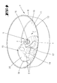
Fig. 1 eine Küchenmaschine der in Rede stehenden Art mit einem in die Maschine eingesetzten Rührgefäß, in Seitenansicht; -
Fig. 2 eine schematische Schnittdarstellung des Bereiches II inFig. 1 , allein den Rührgefäßbodenbereich betreffend; -
Fig. 3 das Rührwerk des Rührgefäßes in perspektivischer Einzeldarstellung; -
Fig. 4 in einer perspektivischen Horizontalschnittdarstellung den Bodenbereich des Rührgefäßes mit darin angeordnetem Rührwerk und weiter in dem Rührgefäß angeordneten Gargutstücken; -
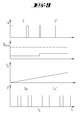
Fig. 5 ein Diagramm zur Darstellung variabler Einschaltintervalle des Rührwerks; -
Fig. 6 ein Diagramm zur Darstellung der variablen Einschaltintervalle der Heizung; -
Fig. 7 ein Diagramm zur Darstellung eines Temperaturanstiegs in Abhängigkeit zur Zeit; -
Fig. 8 eine Diagrammzusammenstellung zur Darstellung des Zusammenhangs von erfasster Garguttemperatur, Temperaturanstieg, Verhältnis von Rührzeiten zu Rühr-Pausenzeiten und Heizzeiten zu Heiz-Pausenzeiten, einen ersten Hauptzustand betreffend; -
Fig. 9 eine derFig. 8 entsprechende Diagrammdarstellung, einen zweiten Hauptzustand betreffend; -
Fig. 10 eine weitere derFig. 8 entsprechende Darstellung, betreffend einen dritten Hauptzustand; -
Fig. 11 eine weitere derFig. 8 entsprechende Darstellung, einen vierten Hauptzustand betreffend; -
Fig. 12 ein Diagramm zur Darstellung der Änderung des Verhältnisses von Rührwerkdreh- zu Pausenzeiten in Abhängigkeit von einer gemessenen Gargut-Ist-Temperatur.
-
Fig. 1 a food processor of the type in question with a mixing vessel inserted into the machine, in side view; -
Fig. 2 a schematic sectional view of the area II inFig. 1 alone concerning the agitator bottom area; -
Fig. 3 the stirrer of the mixing vessel in perspective detail view; -
Fig. 4 in a perspective horizontal sectional view of the bottom portion of the mixing vessel with therein arranged agitator and further arranged in the mixing vessel Gargutstücken; -
Fig. 5 a diagram illustrating variable duty cycle of the agitator; -
Fig. 6 a diagram illustrating the variable switch-on of the heating; -
Fig. 7 a diagram illustrating a temperature rise as a function of time; -
Fig. 8 a diagram for showing the relationship between detected cooking temperature, temperature rise, ratio of stirring times to stirring pause times and heating times to heating pause times, a first main state; -
Fig. 9 one of theFig. 8 corresponding diagram representation concerning a second main state; -
Fig. 10 another oneFig. 8 corresponding representation, concerning a third main state; -
Fig. 11 another oneFig. 8 corresponding representation concerning a fourth main state; -
Fig. 12 a diagram showing the change in the ratio of Rührwerkdreh- to pause times as a function of a measured food temperature actual.
Dargestellt und beschrieben ist zunächst mit Bezug zu
Der Küchenmaschine 1 ist ein Rührgefäß 4 zuordbar, in dem dieses in die Rührgefäßaufnahme 2 eingesetzt wird. Dem Rührgefäßboden 10 ist zugeordnet ein Rührwerk 5 vorgesehen, welches über einen in der Küchenmaschine 1 unterhalb der Aufnahme 2 angeordneten, lediglich schematisch dargestellten Elektroantrieb 6 betrieben wird.The food processor 1 is a mixing
Das in die Rührgefäßaufnahme 2 einzusetzende Rührgefäß 4 besitzt einen senkrecht ausgerichteten Haltegriff 7. Der Sockelbereich 8 des Rührgefäßes 4 ist topfartig mit kreisrundem Querschnitt ausgebildet und zur Beheizung des Rührgefäßes 4 geeignet bzw. hierzu ausgeformt.The mixing
Die mit einem entsprechenden Rührwerk 5 in dem Rührgefäß 4 ausgestattete Küchenmaschine 1 dient in üblicher Weise zum Verrühren, Mixen und/oder Garen von Gargut, wozu weiter das Rührgefäß 4 mittels eines Deckels 9 verschlossen ist.The equipped with a
Über das Bedienfeld 3 ist mittels Schalter und/oder Taster die Rührwerksdrehzahl, darüber hinaus auch die in dem Rührgefäßboden 10 vorgesehene Widerstandsheizung 11 einstellbar.About the
In dem Rührgefäßboden 10, weiter in unmittelbarer Zuordnung zu der unter dem Gefäßboden 10 angeordneten Widerstandsheizung 11 ist ein Heizflächen-Temperaturfühler 12 vorgesehen. Dieser überwacht die Temperatur der Heizleiterbahnen der Widerstandsheizung 11, aus welcher Temperatur die korrespondierende Temperatur an der Bodenoberfläche 13 über den Zusammenhang der Wärmeleitung berechnet werden kann. Die Messwerte werden über eine nicht dargestellte Leitung an eine maschinenseitige Steuereinheit übertragen.In the
Mit vertikalem Abstand von wenigen Millimetern, in dem dargestellten Ausführungsbeispiel etwa 5 mm, oberhalb der Bodenfläche 13 des Rührgefäßes 4 ist ein Medien-Temperaturfühler 14 wandungsinnenseitig des Rührgefäßes 4 vorgesehen. Auch dessen Messinformationen werden über eine Leitung an die Auswerteeinheit übermittelt.With a vertical distance of a few millimeters, in the illustrated embodiment, about 5 mm, above the
Die Lage des Medien-Temperaturfühlers 14 ist oberhalb der Grenzschicht von kritischem Gargut G und außerhalb des direkten Einflusses der Widerstandsheizung 11 gewählt. Dieser Medien-Temperaturfühler 14 dient insbesondere dem Ist-Vergleich der zu erzielenden Gargut-Temperatur und besitzt eine hinreichende Messgenauigkeit.The location of the
Sowohl der Heizflächen-Temperaturfühler 12 als auch der Medien-Temperaturfühler 14 sind in dem dargestellten Ausführungsbeispiel lokal begrenzte Temperatursensoren mit PTC- oder NTC-Verhalten.Both the heating
Alternativ zu der vorgeschlagenen Ausgestaltung des Heizflächen-Temperaturfühlers 12 kann die Temperatur an der Bodenoberfläche 13 auch aus dem Ableitstrom eines Dielektrikums ermittelt werden, welches bspw. zwischen dem, dem aufzuheizenden Gargut zugewandten Heizboden und einer Leiterbahn der Widerstandsheizung 11 angeordnet ist. Über eine vorgesehene Leitung wird der Leckstrom über die weiter vorgesehene Auswerteeinheit der Küchenmaschine 1 zur Steuerung der Heizleistung erfasst.As an alternative to the proposed embodiment of the heating
Die zu den Temperaturfühlern 12 und/oder 14 führenden Leitungen des aus der Küchenmaschine 1 bzw. aus der Rührgefäßaufnahme 2 entnehmbaren Rührgefäßes 4 sind, wie auch die Leitungen zur Spannungsversorgung der Widerstandsheizung über in der Rührgefäßaufnahme 2 vorgesehene, nicht dargestellte Steckkontakte elektrisch kontaktierbar.The leading to the
Das Rührwerk 5 im Rührgefäß 4 ist in dem dargestellten Ausführungsbeispiel mit einem Hebearm 15 versehen. Dieser erstreckt sich in einer Richtung radial ausgehend von der Rührwerkachse x und weist zunächst einen mit der Rührwerkwelle 16 drehfest verbundenen Vertikalabschnitt 17 auf, der in Richtung auf die Bodenfläche 13 gerichtet verläuft. Dieser Vertikalabschnitt 17 trägt endseitig einen Schaufelabschnitt 18, dessen in Drehrichtung r betrachteter Randbereich entgegen der üblichen, messerartigen Ausgestaltung von Rührwerkzeugen einen Stumpfabschnitt 19 ausformt. Dieser bewegt sich zufolge Drehung des Rührwerkes 5 in einer minimal zu der Bodenfläche 13 beabstandeten Parallelebene, weiter bevorzugt in einem Abstand von 1 mm bis 10 mm. In Drehrichtung r dem Stumpfabschnitt 19 folgend ist der Schaufelabschnitt 18 mit einem Anhebeabschnitt 20 versehen, der sich ausgehend von dem Stumpfabschnitt 19 gleichmäßig, schaufelartig gegenüber der Bodenfläche 13 anhebt und somit entsprechend endseitig einen gegenüber dem Stumpfabschnitt 19 vergrößerten vertikalen Abstand zur Bodenfläche 13 aufweist.The
Zufolge der vorbeschriebenen Ausgestaltung des Rührwerkes 5 ist ein Rührwerkzeug geschaffen, dessen Hebearm 15 im Zuge eines Rührens von Gargut G, insbesondere von Gargutstücken, bspw. Fleischstücken, zu einem regelmäßigen Wenden des Garguts führt. Hierbei unterfährt der Stumpfabschnitt 19 des Hebearms 15 das Gargut G zerstörungsfrei, woraufhin zufolge entsprechender Drehung des Hebearms 15 das Gargut G über den Anhebeabschnitt 20 von der Bodenfläche 13 angehoben wird und bevorzugt zufolge Abstützung bzw. Nachrücken folgender Gargutstücke über den in Drehrichtung r endseitigen Rand des Anhebeabschnittes 20 unter Wenden des Gargutstückes abgeworfen wird.According to the above-described embodiment of the
Um insbesondere eine unerwünschte Veränderung der Konsistenz des Garguts G durch zu intensives Rühren und/oder zu intensiver Beheizung entgegenzuwirken, ist eine selbsttätige Steuerung des Rührwerks 5 und/oder der Widerstandsheizung 11 vorgesehen.In order to counteract in particular an undesirable change in the consistency of the food G by excessive stirring and / or intensive heating, an automatic control of the
Während des Kochens von Gargut G mit stückigen Bestandteilen, die erhalten bleiben sollen, wird durch eine Reduktion der mechanischen Bewegungsenergie die Relativbewegung des betreffenden Garguts G zueinander und zur umgebenden Gefäßwandung sowie zum rotierenden Rührwerk 5 minimiert. Die Bewegung geschieht hierbei bedarfsgesteuert selbsttätig bevorzugt aus den aus der Temperaturregelung gewonnenen Kenndaten. Ein gelegentliches Rühren empfindet hierbei das manuelle Umrühren bei der konventionellen Kochmethode nach.During the cooking of food to be cooked with lumpy components that are to be retained, the relative movement of the respective food G to each other and to the surrounding vessel wall and to the
Das Verhältnis von Rührzeiten zu Rührpausenzeiten steht hierbei bevorzugt in einem variablen Verhältnis, wobei als Eingangsgrößen für das Verhältnis und die absolute Dauer der Rührzeit bevorzugt folgende Parameter einzeln oder in Kombination berücksichtigt werden:
- der Motorstrom des Rührwerkantriebs 6 als Kenngröße für das Antriebsmoment;
- der Ist-Temperaturwert der Heizungsregelung über den Medien-
Temperaturfühler 14 als aktuelle Medientemperatur; - der aktuelle Temperaturanstieg;
- das Signal des Heizflächen-
Temperaturfühlers 12, welches ggf. den Zustand eines Anbrennens anzeigt.
- the motor current of the
agitator drive 6 as a parameter for the drive torque; - the actual temperature value of the heating control via the
media temperature sensor 14 as the current medium temperature; - the current temperature increase;
- the signal of the
Heizflächen temperature sensor 12, which may indicate the condition of burning.
Für das gelegentliche Umrühren kann die Rührzeit tR, die Rührpausenzeit tp zwischen zwei aufeinanderfolgenden Rührereignissen, die Zykluszeit tz als Summe von Rührzeit und Rührpausenzeit, sowie das Einschaltverhältnis C=tR/tZ definiert werden (vgl.
Bevorzugt sind diesbezüglich Verhältnisse C von 5 % bis 100%. Die Dauer eines Zyklus tz liegt bevorzugt innerhalb eines Zeitfensters von 30 Sekunden bis 300 Sekunden. Die Vorgabe für diese Parameter ist hierbei bevorzugt abhängig von den Zustandsgrößen der Heizungsregelung und der Veränderung des Aufnahmestroms des Rührwerk-Elektroantriebs 6 als Maß für die Änderung des Motordrehmoments.Ratios C of 5% to 100% are preferred in this regard. The duration of a cycle tz is preferably within a time window of 30 seconds to 300 seconds. The default for these parameters is preferably dependent on the state variables of the heating control and the change in the pick-up current of the agitator
Die Einstellung der mittleren Heizleistung geschieht bevorzugt über ein stetes Ein- und Ausschalten der Heizung mit der vollen Heizleistung (vgl.
Die Berechnung der Einschaltzeit tHE basiert auf der gemessenen Heizungstemperatur TH an dem Heizflächen-Temperaturfühler 12 und ist das Ergebnis des Heizungsregelungsalgorithmus. Aus der gemessenen Heizungstemperatur TH wird über den Zusammenhang der Wärmeleitung der Heizscheibe und des Wärmeübergangs in das Gargut G die tatsächliche Medientemperatur abgeleitet.The calculation of the switch-on time t HE is based on the measured heating temperature T H at the heating
Mit der Temperaturregelung werden die folgenden Zustände verarbeitet:
- aktuelle mittlere Heizleistung aus der Einschaltzeit der Widerstandsheizung 11 und der Nenn-Heizleistung;
- gemessene Ist-Temperatur an
der Widerstandsheizung 11; - Temperaturanstieg TRate aus der Differenz zwischen aktueller Temperatur und der um die feste Zeit At zurückliegend ermittelten Temperatur.
- current average heating power from the switch-on time of the
resistance heater 11 and the nominal heating power; - measured actual temperature at the
resistance heater 11; - Temperature increase T Rate from the difference between the current temperature and the temperature determined by the fixed time Δt.
Wie beispielhaft in
Aus der Einschaltzeit tHE der Widerstandsheizung 11 und dem Temperaturanstieg TRate lassen sich die anhand der
So zeigt die Diagrammzusammenstellung in
Als Reaktion hierauf wird das Verhältnis C von Rührzeit zu Rührpausenzeit beispielhaft nach C' erhöht. Die Einschaltzeit tHE der Widerstandsheizung 11 wird zunächst nicht weiter reduziert, so dass die Einschaltzeit tHE' auch nach dem vorgegebenen Zeitpunkt tE weiter dem Einschaltwert tHE entspricht.In response to this, the ratio C of stirring time to stirring pause time is increased to C 'by way of example. The on-time t HE of the
Bei geringer Einschaltzeit tHE der Heizung und gleichzeitig geringem Temperaturanstieg TRate (vgl.
Gemäß
Als zusätzliche Kenngröße dient die aktuelle Ist-Temperatur des Garguts G. Generell ist insbesondere der Temperaturbereich oberhalb von 70°C kritisch, ab dem z.B. Stärke verkleistert und damit den Wärmeübergang verschlechtert. In diesem Temperaturbereich kann die Erhöhung des Verhältnisses C verstärkt werden, um den Wärmeübergang zu verbessern.As an additional characteristic serves the current actual temperature of the food G. In general, the temperature range above 70 ° C is critical, from the example. Starch gelatinized and thus deteriorates the heat transfer. In this temperature range, the increase in the ratio C can be enhanced to improve the heat transfer.
Die Änderung des Verhältnisses C erfolgt bevorzugt mit verschiedenen Steigungen (vgl. in
Die Änderungsgeschwindigkeit einer Erhöhung des Verhältnisses C erfolgt weiter bevorzugt ebenfalls in Abhängigkeit der Medienviskosität. Die Viskosität wird als relative Viskositätsänderung aus dem Motorstrom des Rührwerkantriebs 6 ermittelt. So kann hierüber bspw. die Zugabe von Mehl, Stärke oder anderer das Gargut G andickender Medien erkannt werden. Bei entsprechender Viskositätsänderung kann der Anstieg des Rührwerk-Einschaltverhältnisses C - mit Bezug auf die Darstellung in
Es erfolgt eine Erhöhung des Verhältnisses C, bis der Temperaturanstieg TRate (ggf. bei gleichzeitiger Reduktion der Einschaltzeit tHE der Heizung) unkritische Werte von ca. 11 K/min erreicht.There is an increase in the ratio C until the temperature rise T Ra te (possibly with simultaneous reduction of the turn-on time t HE of the heater) reaches uncritical values of about 11 K / min.
Die Erhöhung des Verhältnisses C kann bei einem kritischen Temperaturanstieg TRate von mehr als 14 K/min auch direkt auf bis zu 100% erfolgen, bis (ggf. bei gleichzeitiger Reduktion der Einschaltzeit tHE der Heizung) wieder unkritische Werte für TRate erzielt werden.The increase in the ratio C can be carried out at a critical temperature increase T Ra te of more than 14 K / min directly to up to 100%, until (if necessary, while reducing the turn-on t HE of the heater) again uncritical values for T Ra te be achieved.
Alle offenbarten Merkmale sind (für sich) erfindungswesentlich. In die Offenbarung der Anmeldung wird hiermit auch der Offenbarungsinhalt der zugehörigen/beigefügten Prioritätsunterlagen (Abschrift der Voranmeldung) vollinhaltlich mit einbezogen, auch zu dem Zweck, Merkmale dieser Unterlagen in Ansprüche vorliegender Anmeldung mit aufzunehmen. Die Unteransprüche charakterisieren in ihrer fakultativ nebengeordneten Fassung eigenständige erfinderische Weiterbildung des Standes der Technik, insbesondere um auf Basis dieser Ansprüche Teilanmeldungen vorzunehmen.All disclosed features are essential to the invention. The disclosure content of the associated / attached priority documents (copy of the prior application) is hereby also incorporated in full in the disclosure of the application also for the purpose of incorporating features of these documents in claims of the present application. The subclaims characterize in their optional sibling version independent inventive development of the prior art, in particular to make on the basis of these claims divisional applications.
- 1 Küchenmaschine1 food processor
- 2 Rührgefäßaufnahme2 mixing vessel receptacle
- 3 Bedienfeld3 control panel
- 4 Rührgefäß4 stirred vessel
- 5 Rührwerk5 agitator
- 6 Elektroantrieb6 electric drive
- 7 Haltegriff7 handle
- 8 Sockelbereich8 base area
- 9 Deckel9 lids
- 10 Rührgefäßboden10 stirrer bottom
- 11 Widerstandsheizung11 resistance heating
- 12 Heizflächen-Temperaturfühler12 heating surface temperature sensors
- 13 Bodenfläche13 floor area
- 14 Medien-Temperaturfühler14 media temperature sensors
- 15 Hebearm15 lifting arm
- 16 Rührwerkwelle16 agitator shaft
- 17 Vertikalabschnitt17 vertical section
- 18 Schaufelabschnitt18 scoop section
- 19 Stumpfabschnitt19 butt section
- 20 Anhebeabschnitt20 lifting section
- n Drehzahln speed
- r Drehrichtungr direction of rotation
- t Zeitt time
- tE Zeitpunktt E time
- tH Heizzykluszeitt H heating cycle time
- tHA Heizung-Ausschaltzeitt HA heater off time
- tHE Heizung-Einschaltzeitt HE Heating switch-on time
- tHE' Heizung-Einschaltzeitt HE 'Heating on time
- tP Rührpausenzeitt P Rührpausenzeit
- tR Rührzeitt R stirring time
- tZ Rührzykluszeitt Z stirring cycle time
- x Rührwerkachsex agitator axis
- Δt ZeitdifferenzΔt time difference
- C EinschaltverhältnisC duty cycle
- C' EinschaltverhältnisC 'duty cycle
- G GargutG food
- P HeizleistungP heating power
- S1 SteigungS 1 slope
- S2 SteigungS 2 slope
- S3 SteigungS 3 slope
- T TemperaturT temperature
- TH Temperatur-HeizungT H temperature heating
- TRate TemperaturanstiegT Ra te temperature rise
- AT TemperaturdifferenzAT temperature difference
Claims (13)
Priority Applications (4)
| Application Number | Priority Date | Filing Date | Title |
|---|---|---|---|
| EP12155489.3A EP2460452B1 (en) | 2010-06-11 | 2011-06-07 | Kitchen appliance with a mixing container |
| PL11168888T PL2394549T3 (en) | 2010-06-11 | 2011-06-07 | Kitchen appliance with a mixing chamber and method for operating same |
| PL12155489T PL2460452T3 (en) | 2010-06-11 | 2011-06-07 | Kitchen appliance with a mixing container |
| EP14153912.2A EP2730203B1 (en) | 2010-06-11 | 2011-06-07 | Kitchen appliance with a mixing chamber and method for operating the same |
Applications Claiming Priority (1)
| Application Number | Priority Date | Filing Date | Title |
|---|---|---|---|
| DE102010017335A DE102010017335A1 (en) | 2010-06-11 | 2010-06-11 | Food processor with a mixing vessel and method for operating such a food processor |
Related Child Applications (4)
| Application Number | Title | Priority Date | Filing Date |
|---|---|---|---|
| EP14153912.2A Division EP2730203B1 (en) | 2010-06-11 | 2011-06-07 | Kitchen appliance with a mixing chamber and method for operating the same |
| EP14153912.2A Division-Into EP2730203B1 (en) | 2010-06-11 | 2011-06-07 | Kitchen appliance with a mixing chamber and method for operating the same |
| EP12155489.3A Division-Into EP2460452B1 (en) | 2010-06-11 | 2011-06-07 | Kitchen appliance with a mixing container |
| EP12155489.3A Division EP2460452B1 (en) | 2010-06-11 | 2011-06-07 | Kitchen appliance with a mixing container |
Publications (3)
| Publication Number | Publication Date |
|---|---|
| EP2394549A2 true EP2394549A2 (en) | 2011-12-14 |
| EP2394549A3 EP2394549A3 (en) | 2011-12-21 |
| EP2394549B1 EP2394549B1 (en) | 2014-05-21 |
Family
ID=44461862
Family Applications (3)
| Application Number | Title | Priority Date | Filing Date |
|---|---|---|---|
| EP11168888.3A Active EP2394549B1 (en) | 2010-06-11 | 2011-06-07 | Kitchen appliance with a mixing chamber and method for operating same |
| EP14153912.2A Active EP2730203B1 (en) | 2010-06-11 | 2011-06-07 | Kitchen appliance with a mixing chamber and method for operating the same |
| EP12155489.3A Active EP2460452B1 (en) | 2010-06-11 | 2011-06-07 | Kitchen appliance with a mixing container |
Family Applications After (2)
| Application Number | Title | Priority Date | Filing Date |
|---|---|---|---|
| EP14153912.2A Active EP2730203B1 (en) | 2010-06-11 | 2011-06-07 | Kitchen appliance with a mixing chamber and method for operating the same |
| EP12155489.3A Active EP2460452B1 (en) | 2010-06-11 | 2011-06-07 | Kitchen appliance with a mixing container |
Country Status (6)
| Country | Link |
|---|---|
| EP (3) | EP2394549B1 (en) |
| CN (3) | CN102362791B (en) |
| DE (1) | DE102010017335A1 (en) |
| ES (3) | ES2513615T3 (en) |
| PL (3) | PL2460452T3 (en) |
| PT (3) | PT2460452E (en) |
Cited By (10)
| Publication number | Priority date | Publication date | Assignee | Title |
|---|---|---|---|---|
| GB2498342A (en) * | 2012-01-10 | 2013-07-17 | Kenwood Ltd | Food processing tool |
| WO2014016117A1 (en) * | 2012-07-23 | 2014-01-30 | Vorwerk & Co. Interholding Gmbh | Kitchen appliance |
| WO2017089828A1 (en) * | 2015-11-25 | 2017-06-01 | Kenwood Limited | Stirring tool |
| WO2017211963A1 (en) * | 2016-06-10 | 2017-12-14 | Vorwerk & Co. Interholding Gmbh | Automatic control function for whipping cream |
| FR3059535A1 (en) * | 2016-12-07 | 2018-06-08 | Seb S.A. | STEERING PROCESS AND HEATING MIXER CULINARY PREPARATION ELECTRICAL APPLIANCE |
| US20180184848A1 (en) * | 2015-06-12 | 2018-07-05 | De' Longhi Appliances S.R.L.Con Unico Socio | Apparatus for Cooking Foods |
| FR3068133A1 (en) * | 2017-06-27 | 2018-12-28 | Seb S.A. | PROCESS FOR CONTROLLING THE TEXTURE OF A CULINARY PREPARATION |
| CN109645852A (en) * | 2017-10-11 | 2019-04-19 | 德国福维克控股公司 | The kitchen machine and stirring vessel and blender of electric operation |
| CN112294147A (en) * | 2019-07-30 | 2021-02-02 | Bsh家用电器有限公司 | Kitchen machine and method for operating a stirring tool of a kitchen machine |
| CN114271666A (en) * | 2020-09-27 | 2022-04-05 | 珠海优特智厨科技有限公司 | Control method of cooking appliance, storage medium and computer device |
Families Citing this family (13)
| Publication number | Priority date | Publication date | Assignee | Title |
|---|---|---|---|---|
| DE102010017335A1 (en) * | 2010-06-11 | 2011-12-15 | Vorwerk & Co. Interholding Gmbh | Food processor with a mixing vessel and method for operating such a food processor |
| US9049967B1 (en) | 2014-08-08 | 2015-06-09 | Euro-Pro Operating Llc | Food processing apparatus and method |
| DE102014115322A1 (en) | 2014-10-21 | 2016-04-21 | Vorwerk & Co. Interholding Gmbh | Food processor with cooling device |
| DE102015103596A1 (en) * | 2015-03-11 | 2016-09-15 | Vorwerk & Co. Interholding Gmbh | Method for operating an electric motor driven food processor |
| WO2016200891A1 (en) * | 2015-06-08 | 2016-12-15 | Sharkninja Operating Llc | Food processing apparatus and method |
| DE102016110710A1 (en) * | 2016-06-10 | 2017-12-14 | Vorwerk & Co. Interholding Gmbh | Method for operating a food processor |
| CN108552976B (en) * | 2016-06-23 | 2020-09-25 | 磐安县嘉嘉工业设计有限公司 | Bread machine stirring head, bread machine and bread making method |
| CN107802184B (en) * | 2016-09-09 | 2023-08-08 | 佛山市顺德区美的电热电器制造有限公司 | Cooking stirring rake and cooking machine with same |
| ES2927247T3 (en) * | 2018-01-17 | 2022-11-03 | Vorwerk Co Interholding | Procedure for operating a heating element |
| CN110115494B (en) * | 2018-02-05 | 2021-12-03 | 佛山市顺德区美的电热电器制造有限公司 | Cooking machine, control method thereof, and computer-readable storage medium |
| CA3145227A1 (en) * | 2019-07-11 | 2021-01-14 | Societe Des Produits Nestle S.A. | Regulation of wisking of a food substance |
| DE102019211283A1 (en) * | 2019-07-30 | 2021-02-04 | BSH Hausgeräte GmbH | Kitchen machine and method for increasing the safety of a kitchen machine |
| CN115399631B (en) * | 2021-05-28 | 2023-12-15 | 佛山市顺德区美的电热电器制造有限公司 | Stirring control method, cooking device, control device, and readable storage medium |
Family Cites Families (22)
| Publication number | Priority date | Publication date | Assignee | Title |
|---|---|---|---|---|
| US4312596A (en) * | 1978-05-24 | 1982-01-26 | Tokyo Electric Limited | Beating blade member of beater |
| US4541573A (en) * | 1982-08-05 | 1985-09-17 | Sanyo Electric Co., Ltd. | Food processor |
| US4691870A (en) | 1984-10-09 | 1987-09-08 | Matsushita Electric Industrial Co. | Electric food processor |
| DE4414825A1 (en) * | 1994-04-28 | 1995-11-02 | Vorwerk Co Interholding | Food processor with a mixing vessel and a drive for an agitator in the mixing vessel |
| JPH10192158A (en) * | 1996-12-30 | 1998-07-28 | Sanyo Electric Co Ltd | Mixer |
| DE20017064U1 (en) | 2000-10-02 | 2000-12-21 | Dominik, Hans, 72461 Albstadt | Device for detecting the rear and side space of a vehicle |
| DE102004005607A1 (en) * | 2004-02-05 | 2005-09-01 | Vorwerk & Co. Interholding Gmbh | Process for preparing food by means of a kitchen appliance and kitchen appliance |
| CN100508853C (en) * | 2005-04-26 | 2009-07-08 | 厦门灿坤实业股份有限公司 | Food conditioner with self-judging condition |
| FR2896677B1 (en) * | 2006-02-01 | 2010-08-20 | Seb Sa | COOKING APPARATUS WITH MEANS OF REMUTING AND METHOD THEREOF |
| DE102006042990B3 (en) * | 2006-09-13 | 2008-04-03 | BSH Bosch und Siemens Hausgeräte GmbH | Strainer |
| FR2908621A1 (en) * | 2006-11-17 | 2008-05-23 | Seb Sa | ROTARY WORKING TOOL FOR CULINARY PREPARATION ELECTRICAL APPLIANCES, ESPECIALLY CONFITURING |
| US7641380B2 (en) * | 2007-02-16 | 2010-01-05 | Sunbeam Products, Inc. | Blender/food processor blade arrangement for small throated blender jars |
| US7581688B2 (en) * | 2007-03-12 | 2009-09-01 | Whirlpool Corporation | Blender with crushed ice functionality |
| DE102007056711B4 (en) | 2007-11-26 | 2013-11-14 | BSH Bosch und Siemens Hausgeräte GmbH | Kneading or stirring tool and food processor |
| DE102008038783B4 (en) * | 2008-08-12 | 2017-11-09 | Vorwerk & Co. Interholding Gmbh | Food processor with a mixing vessel and method for this |
| CN201335991Y (en) * | 2009-01-12 | 2009-10-28 | 励土峰 | Temperature detecting device for soymilk machine |
| CN201422778Y (en) * | 2009-03-20 | 2010-03-17 | 米乐美电器(苏州)有限公司 | Food mixer |
| CN201445415U (en) * | 2009-06-03 | 2010-05-05 | 佛山市科嘉霖电器制造有限公司 | Heating type food mixer |
| CN201445420U (en) * | 2009-07-15 | 2010-05-05 | 罗全恩 | Driving device for charging hopper of multifunctional household food processor |
| CN101642353A (en) * | 2009-09-08 | 2010-02-10 | 王晓东 | Smashing cutter structure of food processor |
| CN101708112A (en) * | 2009-11-05 | 2010-05-19 | 顾永洪 | Crushing blade |
| DE102010017335A1 (en) * | 2010-06-11 | 2011-12-15 | Vorwerk & Co. Interholding Gmbh | Food processor with a mixing vessel and method for operating such a food processor |
-
2010
- 2010-06-11 DE DE102010017335A patent/DE102010017335A1/en not_active Withdrawn
-
2011
- 2011-06-07 ES ES12155489.3T patent/ES2513615T3/en active Active
- 2011-06-07 PT PT121554893T patent/PT2460452E/en unknown
- 2011-06-07 EP EP11168888.3A patent/EP2394549B1/en active Active
- 2011-06-07 PL PL12155489T patent/PL2460452T3/en unknown
- 2011-06-07 EP EP14153912.2A patent/EP2730203B1/en active Active
- 2011-06-07 PL PL14153912T patent/PL2730203T3/en unknown
- 2011-06-07 ES ES14153912.2T patent/ES2614378T3/en active Active
- 2011-06-07 PL PL11168888T patent/PL2394549T3/en unknown
- 2011-06-07 EP EP12155489.3A patent/EP2460452B1/en active Active
- 2011-06-07 ES ES11168888.3T patent/ES2477282T3/en active Active
- 2011-06-07 PT PT141539122T patent/PT2730203T/en unknown
- 2011-06-07 PT PT111688883T patent/PT2394549E/en unknown
- 2011-06-13 CN CN201110275089.9A patent/CN102362791B/en active Active
- 2011-06-13 CN CN201510388426.3A patent/CN104970716B/en active Active
- 2011-06-13 CN CN201410706039.5A patent/CN104382504B/en active Active
Non-Patent Citations (1)
| Title |
|---|
| None |
Cited By (24)
| Publication number | Priority date | Publication date | Assignee | Title |
|---|---|---|---|---|
| GB2498342A (en) * | 2012-01-10 | 2013-07-17 | Kenwood Ltd | Food processing tool |
| US9681778B2 (en) | 2012-01-10 | 2017-06-20 | Kenwood Limited | Food processing tool |
| GB2498342B (en) * | 2012-01-10 | 2017-08-02 | Kenwood Ltd | Food processing tool |
| TWI610644B (en) * | 2012-07-23 | 2018-01-11 | 佛維爾克控股公司 | Electrically driveable kitchen appliance and method for automatically preparing food |
| WO2014016117A1 (en) * | 2012-07-23 | 2014-01-30 | Vorwerk & Co. Interholding Gmbh | Kitchen appliance |
| AU2013295207B2 (en) * | 2012-07-23 | 2017-01-19 | Vorwerk & Co. Interholding Gmbh | Kitchen appliance |
| CN106983375A (en) * | 2012-07-23 | 2017-07-28 | 德国福维克控股公司 | Cooking apparatus |
| US10856696B2 (en) * | 2015-06-12 | 2020-12-08 | De' Longhi Appliances S.R.L. Con Unico Socio | Apparatus for cooking foods |
| US20180184848A1 (en) * | 2015-06-12 | 2018-07-05 | De' Longhi Appliances S.R.L.Con Unico Socio | Apparatus for Cooking Foods |
| US11109714B2 (en) | 2015-11-25 | 2021-09-07 | Kenwood Limited | Stirring tool |
| GB2544967A (en) * | 2015-11-25 | 2017-06-07 | Kenwood Ltd | Stirring tool |
| WO2017089828A1 (en) * | 2015-11-25 | 2017-06-01 | Kenwood Limited | Stirring tool |
| US11278155B2 (en) | 2016-06-10 | 2022-03-22 | Vorwerk & Co. Interholding Gmbh | Automatic control function for whipping cream |
| CN109310244A (en) * | 2016-06-10 | 2019-02-05 | 德国福维克控股公司 | Automatic control function for Whipped cream |
| WO2017211963A1 (en) * | 2016-06-10 | 2017-12-14 | Vorwerk & Co. Interholding Gmbh | Automatic control function for whipping cream |
| CN109310244B (en) * | 2016-06-10 | 2022-08-23 | 德国福维克控股公司 | Automatic control function for whipped cream |
| FR3059535A1 (en) * | 2016-12-07 | 2018-06-08 | Seb S.A. | STEERING PROCESS AND HEATING MIXER CULINARY PREPARATION ELECTRICAL APPLIANCE |
| WO2019002738A1 (en) * | 2017-06-27 | 2019-01-03 | Seb S.A. | Method for controlling the texture of a culinary preparation |
| FR3068133A1 (en) * | 2017-06-27 | 2018-12-28 | Seb S.A. | PROCESS FOR CONTROLLING THE TEXTURE OF A CULINARY PREPARATION |
| CN109645852A (en) * | 2017-10-11 | 2019-04-19 | 德国福维克控股公司 | The kitchen machine and stirring vessel and blender of electric operation |
| CN109645852B (en) * | 2017-10-11 | 2023-08-22 | 德国福维克控股公司 | Electric kitchen appliance and stirring vessel and stirrer |
| CN112294147A (en) * | 2019-07-30 | 2021-02-02 | Bsh家用电器有限公司 | Kitchen machine and method for operating a stirring tool of a kitchen machine |
| CN114271666A (en) * | 2020-09-27 | 2022-04-05 | 珠海优特智厨科技有限公司 | Control method of cooking appliance, storage medium and computer device |
| CN114271666B (en) * | 2020-09-27 | 2023-07-18 | 珠海优特智厨科技有限公司 | Control method of cooking utensil, storage medium and computer equipment |
Also Published As
| Publication number | Publication date |
|---|---|
| CN104970716A (en) | 2015-10-14 |
| CN102362791B (en) | 2016-06-01 |
| CN104382504B (en) | 2017-05-24 |
| PT2730203T (en) | 2017-03-10 |
| ES2477282T3 (en) | 2014-07-16 |
| EP2730203B1 (en) | 2016-12-07 |
| EP2730203A1 (en) | 2014-05-14 |
| PT2394549E (en) | 2014-06-05 |
| ES2614378T3 (en) | 2017-05-30 |
| EP2394549A3 (en) | 2011-12-21 |
| EP2394549B1 (en) | 2014-05-21 |
| EP2460452A1 (en) | 2012-06-06 |
| CN104382504A (en) | 2015-03-04 |
| EP2460452B1 (en) | 2014-08-20 |
| PL2394549T3 (en) | 2014-09-30 |
| PL2730203T3 (en) | 2017-05-31 |
| CN104970716B (en) | 2018-08-28 |
| PT2460452E (en) | 2014-09-09 |
| DE102010017335A1 (en) | 2011-12-15 |
| ES2513615T3 (en) | 2014-10-27 |
| CN102362791A (en) | 2012-02-29 |
| PL2460452T3 (en) | 2014-11-28 |
Similar Documents
| Publication | Publication Date | Title |
|---|---|---|
| EP2394549B1 (en) | Kitchen appliance with a mixing chamber and method for operating same | |
| DE102010037769B4 (en) | Electrically operated food processor and method for operating such a food processor | |
| DE102008038783B4 (en) | Food processor with a mixing vessel and method for this | |
| EP0757529B1 (en) | Food processor with a mixing vessel and a drive mechanism for an agitator in the mixing vessel | |
| EP2874526B1 (en) | Kitchen machine | |
| DE102011052405B4 (en) | About a designed as a touchscreen display to be operated food processor | |
| DE102010016024B4 (en) | food processor | |
| EP2529650B1 (en) | Method for releasing a lid of a supply vessel and kitchen appliance with a cooking container | |
| EP3482661B1 (en) | Method for adapting a heating output of at least one heating element of a domestic appliance | |
| DE202011050875U1 (en) | Food processor with a mixing vessel | |
| EP3415061B1 (en) | Domestic appliance | |
| DE102010000299B4 (en) | food processor | |
| EP2805655A1 (en) | Electric motor-operated kitchen appliance, and method for cleaning such a kitchen appliance | |
| DE60214214T2 (en) | DEVICE AND METHOD FOR COOKING FOODS WITH MICROWAVES | |
| EP3936014B1 (en) | Food preparation device for cutting food, crushing attachment and method | |
| DE69700344T2 (en) | Method of controlling a microwave oven to avoid overcooking small portions of food | |
| EP4026460B1 (en) | Food preparation device for cutting food, crushing attachment and method | |
| EP3973831B1 (en) | Kitchen appliance and method for taking a food sample | |
| EP4101349A1 (en) | Method for potato peeling and kitchen appliance | |
| DE102012220996A1 (en) | Kitchen equipment for processing of foodstuffs, has unit for detection of electrical conductivity of to-be processed foodstuffs, where electrical conductivity detecting unit is connected with control unit | |
| EP4272614A1 (en) | Kitchen appliance with scale for user interface | |
| DE102020112626A1 (en) | Induction hob with a hob plate | |
| EP4382008A1 (en) | System with pressure cooker and method | |
| DE1007482B (en) | Electromotive drive base for attachable household kitchen appliances |
Legal Events
| Date | Code | Title | Description |
|---|---|---|---|
| PUAL | Search report despatched |
Free format text: ORIGINAL CODE: 0009013 |
|
| AK | Designated contracting states |
Kind code of ref document: A2 Designated state(s): AL AT BE BG CH CY CZ DE DK EE ES FI FR GB GR HR HU IE IS IT LI LT LU LV MC MK MT NL NO PL PT RO RS SE SI SK SM TR |
|
| AX | Request for extension of the european patent |
Extension state: BA ME |
|
| PUAI | Public reference made under article 153(3) epc to a published international application that has entered the european phase |
Free format text: ORIGINAL CODE: 0009012 |
|
| AK | Designated contracting states |
Kind code of ref document: A3 Designated state(s): AL AT BE BG CH CY CZ DE DK EE ES FI FR GB GR HR HU IE IS IT LI LT LU LV MC MK MT NL NO PL PT RO RS SE SI SK SM TR |
|
| AX | Request for extension of the european patent |
Extension state: BA ME |
|
| RIC1 | Information provided on ipc code assigned before grant |
Ipc: A47J 43/08 20060101AFI20111115BHEP Ipc: A47J 43/07 20060101ALI20111115BHEP |
|
| 17P | Request for examination filed |
Effective date: 20120308 |
|
| 17Q | First examination report despatched |
Effective date: 20130311 |
|
| GRAP | Despatch of communication of intention to grant a patent |
Free format text: ORIGINAL CODE: EPIDOSNIGR1 |
|
| INTG | Intention to grant announced |
Effective date: 20131212 |
|
| GRAS | Grant fee paid |
Free format text: ORIGINAL CODE: EPIDOSNIGR3 |
|
| GRAA | (expected) grant |
Free format text: ORIGINAL CODE: 0009210 |
|
| AK | Designated contracting states |
Kind code of ref document: B1 Designated state(s): AL AT BE BG CH CY CZ DE DK EE ES FI FR GB GR HR HU IE IS IT LI LT LU LV MC MK MT NL NO PL PT RO RS SE SI SK SM TR |
|
| REG | Reference to a national code |
Ref country code: GB Ref legal event code: FG4D Free format text: NOT ENGLISH |
|
| REG | Reference to a national code |
Ref country code: CH Ref legal event code: EP |
|
| REG | Reference to a national code |
Ref country code: PT Ref legal event code: SC4A Free format text: AVAILABILITY OF NATIONAL TRANSLATION Effective date: 20140529 |
|
| REG | Reference to a national code |
Ref country code: AT Ref legal event code: REF Ref document number: 669157 Country of ref document: AT Kind code of ref document: T Effective date: 20140615 |
|
| REG | Reference to a national code |
Ref country code: IE Ref legal event code: FG4D Free format text: LANGUAGE OF EP DOCUMENT: GERMAN |
|
| REG | Reference to a national code |
Ref country code: DE Ref legal event code: R096 Ref document number: 502011003177 Country of ref document: DE Effective date: 20140703 |
|
| REG | Reference to a national code |
Ref country code: ES Ref legal event code: FG2A Ref document number: 2477282 Country of ref document: ES Kind code of ref document: T3 Effective date: 20140716 |
|
| REG | Reference to a national code |
Ref country code: PL Ref legal event code: T3 |
|
| REG | Reference to a national code |
Ref country code: NL Ref legal event code: VDEP Effective date: 20140521 |
|
| REG | Reference to a national code |
Ref country code: LT Ref legal event code: MG4D |
|
| PG25 | Lapsed in a contracting state [announced via postgrant information from national office to epo] |
Ref country code: FI Free format text: LAPSE BECAUSE OF FAILURE TO SUBMIT A TRANSLATION OF THE DESCRIPTION OR TO PAY THE FEE WITHIN THE PRESCRIBED TIME-LIMIT Effective date: 20140521 Ref country code: GR Free format text: LAPSE BECAUSE OF FAILURE TO SUBMIT A TRANSLATION OF THE DESCRIPTION OR TO PAY THE FEE WITHIN THE PRESCRIBED TIME-LIMIT Effective date: 20140822 Ref country code: LT Free format text: LAPSE BECAUSE OF FAILURE TO SUBMIT A TRANSLATION OF THE DESCRIPTION OR TO PAY THE FEE WITHIN THE PRESCRIBED TIME-LIMIT Effective date: 20140521 Ref country code: IS Free format text: LAPSE BECAUSE OF FAILURE TO SUBMIT A TRANSLATION OF THE DESCRIPTION OR TO PAY THE FEE WITHIN THE PRESCRIBED TIME-LIMIT Effective date: 20140921 Ref country code: NO Free format text: LAPSE BECAUSE OF FAILURE TO SUBMIT A TRANSLATION OF THE DESCRIPTION OR TO PAY THE FEE WITHIN THE PRESCRIBED TIME-LIMIT Effective date: 20140821 |
|
| PG25 | Lapsed in a contracting state [announced via postgrant information from national office to epo] |
Ref country code: SE Free format text: LAPSE BECAUSE OF FAILURE TO SUBMIT A TRANSLATION OF THE DESCRIPTION OR TO PAY THE FEE WITHIN THE PRESCRIBED TIME-LIMIT Effective date: 20140521 Ref country code: LV Free format text: LAPSE BECAUSE OF FAILURE TO SUBMIT A TRANSLATION OF THE DESCRIPTION OR TO PAY THE FEE WITHIN THE PRESCRIBED TIME-LIMIT Effective date: 20140521 Ref country code: HR Free format text: LAPSE BECAUSE OF FAILURE TO SUBMIT A TRANSLATION OF THE DESCRIPTION OR TO PAY THE FEE WITHIN THE PRESCRIBED TIME-LIMIT Effective date: 20140521 Ref country code: RS Free format text: LAPSE BECAUSE OF FAILURE TO SUBMIT A TRANSLATION OF THE DESCRIPTION OR TO PAY THE FEE WITHIN THE PRESCRIBED TIME-LIMIT Effective date: 20140521 |
|
| PG25 | Lapsed in a contracting state [announced via postgrant information from national office to epo] |
Ref country code: DK Free format text: LAPSE BECAUSE OF FAILURE TO SUBMIT A TRANSLATION OF THE DESCRIPTION OR TO PAY THE FEE WITHIN THE PRESCRIBED TIME-LIMIT Effective date: 20140521 Ref country code: SK Free format text: LAPSE BECAUSE OF FAILURE TO SUBMIT A TRANSLATION OF THE DESCRIPTION OR TO PAY THE FEE WITHIN THE PRESCRIBED TIME-LIMIT Effective date: 20140521 Ref country code: EE Free format text: LAPSE BECAUSE OF FAILURE TO SUBMIT A TRANSLATION OF THE DESCRIPTION OR TO PAY THE FEE WITHIN THE PRESCRIBED TIME-LIMIT Effective date: 20140521 Ref country code: RO Free format text: LAPSE BECAUSE OF FAILURE TO SUBMIT A TRANSLATION OF THE DESCRIPTION OR TO PAY THE FEE WITHIN THE PRESCRIBED TIME-LIMIT Effective date: 20140521 Ref country code: CZ Free format text: LAPSE BECAUSE OF FAILURE TO SUBMIT A TRANSLATION OF THE DESCRIPTION OR TO PAY THE FEE WITHIN THE PRESCRIBED TIME-LIMIT Effective date: 20140521 |
|
| REG | Reference to a national code |
Ref country code: CH Ref legal event code: PL |
|
| REG | Reference to a national code |
Ref country code: DE Ref legal event code: R097 Ref document number: 502011003177 Country of ref document: DE |
|
| PG25 | Lapsed in a contracting state [announced via postgrant information from national office to epo] |
Ref country code: NL Free format text: LAPSE BECAUSE OF FAILURE TO SUBMIT A TRANSLATION OF THE DESCRIPTION OR TO PAY THE FEE WITHIN THE PRESCRIBED TIME-LIMIT Effective date: 20140521 |
|
| REG | Reference to a national code |
Ref country code: IE Ref legal event code: MM4A |
|
| PLBE | No opposition filed within time limit |
Free format text: ORIGINAL CODE: 0009261 |
|
| STAA | Information on the status of an ep patent application or granted ep patent |
Free format text: STATUS: NO OPPOSITION FILED WITHIN TIME LIMIT |
|
| 26N | No opposition filed |
Effective date: 20150224 |
|
| PG25 | Lapsed in a contracting state [announced via postgrant information from national office to epo] |
Ref country code: LI Free format text: LAPSE BECAUSE OF NON-PAYMENT OF DUE FEES Effective date: 20140630 Ref country code: IE Free format text: LAPSE BECAUSE OF NON-PAYMENT OF DUE FEES Effective date: 20140607 Ref country code: CH Free format text: LAPSE BECAUSE OF NON-PAYMENT OF DUE FEES Effective date: 20140630 |
|
| REG | Reference to a national code |
Ref country code: DE Ref legal event code: R097 Ref document number: 502011003177 Country of ref document: DE Effective date: 20150224 |
|
| PG25 | Lapsed in a contracting state [announced via postgrant information from national office to epo] |
Ref country code: SI Free format text: LAPSE BECAUSE OF FAILURE TO SUBMIT A TRANSLATION OF THE DESCRIPTION OR TO PAY THE FEE WITHIN THE PRESCRIBED TIME-LIMIT Effective date: 20140521 |
|
| GBPC | Gb: european patent ceased through non-payment of renewal fee |
Effective date: 20150607 |
|
| PG25 | Lapsed in a contracting state [announced via postgrant information from national office to epo] |
Ref country code: MT Free format text: LAPSE BECAUSE OF FAILURE TO SUBMIT A TRANSLATION OF THE DESCRIPTION OR TO PAY THE FEE WITHIN THE PRESCRIBED TIME-LIMIT Effective date: 20140521 |
|
| PG25 | Lapsed in a contracting state [announced via postgrant information from national office to epo] |
Ref country code: MC Free format text: LAPSE BECAUSE OF FAILURE TO SUBMIT A TRANSLATION OF THE DESCRIPTION OR TO PAY THE FEE WITHIN THE PRESCRIBED TIME-LIMIT Effective date: 20140521 Ref country code: SM Free format text: LAPSE BECAUSE OF FAILURE TO SUBMIT A TRANSLATION OF THE DESCRIPTION OR TO PAY THE FEE WITHIN THE PRESCRIBED TIME-LIMIT Effective date: 20140521 Ref country code: GB Free format text: LAPSE BECAUSE OF NON-PAYMENT OF DUE FEES Effective date: 20150607 |
|
| REG | Reference to a national code |
Ref country code: FR Ref legal event code: PLFP Year of fee payment: 6 |
|
| PG25 | Lapsed in a contracting state [announced via postgrant information from national office to epo] |
Ref country code: CY Free format text: LAPSE BECAUSE OF FAILURE TO SUBMIT A TRANSLATION OF THE DESCRIPTION OR TO PAY THE FEE WITHIN THE PRESCRIBED TIME-LIMIT Effective date: 20140521 Ref country code: BG Free format text: LAPSE BECAUSE OF FAILURE TO SUBMIT A TRANSLATION OF THE DESCRIPTION OR TO PAY THE FEE WITHIN THE PRESCRIBED TIME-LIMIT Effective date: 20140521 |
|
| PG25 | Lapsed in a contracting state [announced via postgrant information from national office to epo] |
Ref country code: TR Free format text: LAPSE BECAUSE OF FAILURE TO SUBMIT A TRANSLATION OF THE DESCRIPTION OR TO PAY THE FEE WITHIN THE PRESCRIBED TIME-LIMIT Effective date: 20140521 Ref country code: HU Free format text: LAPSE BECAUSE OF FAILURE TO SUBMIT A TRANSLATION OF THE DESCRIPTION OR TO PAY THE FEE WITHIN THE PRESCRIBED TIME-LIMIT; INVALID AB INITIO Effective date: 20110607 Ref country code: BE Free format text: LAPSE BECAUSE OF FAILURE TO SUBMIT A TRANSLATION OF THE DESCRIPTION OR TO PAY THE FEE WITHIN THE PRESCRIBED TIME-LIMIT Effective date: 20140630 Ref country code: LU Free format text: LAPSE BECAUSE OF NON-PAYMENT OF DUE FEES Effective date: 20140607 |
|
| REG | Reference to a national code |
Ref country code: FR Ref legal event code: PLFP Year of fee payment: 7 |
|
| REG | Reference to a national code |
Ref country code: AT Ref legal event code: MM01 Ref document number: 669157 Country of ref document: AT Kind code of ref document: T Effective date: 20160607 |
|
| PG25 | Lapsed in a contracting state [announced via postgrant information from national office to epo] |
Ref country code: AT Free format text: LAPSE BECAUSE OF NON-PAYMENT OF DUE FEES Effective date: 20160607 |
|
| REG | Reference to a national code |
Ref country code: FR Ref legal event code: PLFP Year of fee payment: 8 |
|
| PG25 | Lapsed in a contracting state [announced via postgrant information from national office to epo] |
Ref country code: MK Free format text: LAPSE BECAUSE OF FAILURE TO SUBMIT A TRANSLATION OF THE DESCRIPTION OR TO PAY THE FEE WITHIN THE PRESCRIBED TIME-LIMIT Effective date: 20140521 |
|
| PG25 | Lapsed in a contracting state [announced via postgrant information from national office to epo] |
Ref country code: AL Free format text: LAPSE BECAUSE OF FAILURE TO SUBMIT A TRANSLATION OF THE DESCRIPTION OR TO PAY THE FEE WITHIN THE PRESCRIBED TIME-LIMIT Effective date: 20140521 |
|
| P01 | Opt-out of the competence of the unified patent court (upc) registered |
Effective date: 20230517 |
|
| PGFP | Annual fee paid to national office [announced via postgrant information from national office to epo] |
Ref country code: IT Payment date: 20230630 Year of fee payment: 13 Ref country code: ES Payment date: 20230719 Year of fee payment: 13 |
|
| PGFP | Annual fee paid to national office [announced via postgrant information from national office to epo] |
Ref country code: DE Payment date: 20240617 Year of fee payment: 14 |
|
| PGFP | Annual fee paid to national office [announced via postgrant information from national office to epo] |
Ref country code: FR Payment date: 20240621 Year of fee payment: 14 |
|
| PGFP | Annual fee paid to national office [announced via postgrant information from national office to epo] |
Ref country code: PL Payment date: 20240524 Year of fee payment: 14 Ref country code: PT Payment date: 20240529 Year of fee payment: 14 |