EP2394085B1 - Structure formed of multiple pipe or cable lead-through blocks - Google Patents
Structure formed of multiple pipe or cable lead-through blocks Download PDFInfo
- Publication number
- EP2394085B1 EP2394085B1 EP10738815.9A EP10738815A EP2394085B1 EP 2394085 B1 EP2394085 B1 EP 2394085B1 EP 10738815 A EP10738815 A EP 10738815A EP 2394085 B1 EP2394085 B1 EP 2394085B1
- Authority
- EP
- European Patent Office
- Prior art keywords
- blocks
- block
- frame
- protruding parts
- openings
- Prior art date
- Legal status (The legal status is an assumption and is not a legal conclusion. Google has not performed a legal analysis and makes no representation as to the accuracy of the status listed.)
- Active
Links
- 230000007704 transition Effects 0.000 claims description 6
- 230000000295 complement effect Effects 0.000 claims description 3
- UQDJGEHQDNVPGU-UHFFFAOYSA-N serine phosphoethanolamine Chemical compound [NH3+]CCOP([O-])(=O)OCC([NH3+])C([O-])=O UQDJGEHQDNVPGU-UHFFFAOYSA-N 0.000 claims description 3
- 230000006835 compression Effects 0.000 description 6
- 238000007906 compression Methods 0.000 description 6
- 239000013013 elastic material Substances 0.000 description 3
- 239000007789 gas Substances 0.000 description 3
- 238000009434 installation Methods 0.000 description 3
- 239000000463 material Substances 0.000 description 3
- 230000035515 penetration Effects 0.000 description 3
- 238000007789 sealing Methods 0.000 description 3
- 239000012530 fluid Substances 0.000 description 2
- 230000014509 gene expression Effects 0.000 description 2
- 241000256602 Isoptera Species 0.000 description 1
- 241000283984 Rodentia Species 0.000 description 1
- 239000000853 adhesive Substances 0.000 description 1
- 230000001070 adhesive effect Effects 0.000 description 1
- 238000010411 cooking Methods 0.000 description 1
- 230000001419 dependent effect Effects 0.000 description 1
- 239000000428 dust Substances 0.000 description 1
- 230000000694 effects Effects 0.000 description 1
- 230000005611 electricity Effects 0.000 description 1
- 239000007788 liquid Substances 0.000 description 1
- 238000005461 lubrication Methods 0.000 description 1
- 230000014759 maintenance of location Effects 0.000 description 1
- 238000004519 manufacturing process Methods 0.000 description 1
- 238000010248 power generation Methods 0.000 description 1
- XLYOFNOQVPJJNP-UHFFFAOYSA-N water Substances O XLYOFNOQVPJJNP-UHFFFAOYSA-N 0.000 description 1
Images


Classifications
-
- F—MECHANICAL ENGINEERING; LIGHTING; HEATING; WEAPONS; BLASTING
- F16—ENGINEERING ELEMENTS AND UNITS; GENERAL MEASURES FOR PRODUCING AND MAINTAINING EFFECTIVE FUNCTIONING OF MACHINES OR INSTALLATIONS; THERMAL INSULATION IN GENERAL
- F16L—PIPES; JOINTS OR FITTINGS FOR PIPES; SUPPORTS FOR PIPES, CABLES OR PROTECTIVE TUBING; MEANS FOR THERMAL INSULATION IN GENERAL
- F16L5/00—Devices for use where pipes, cables or protective tubing pass through walls or partitions
- F16L5/02—Sealing
-
- F—MECHANICAL ENGINEERING; LIGHTING; HEATING; WEAPONS; BLASTING
- F16—ENGINEERING ELEMENTS AND UNITS; GENERAL MEASURES FOR PRODUCING AND MAINTAINING EFFECTIVE FUNCTIONING OF MACHINES OR INSTALLATIONS; THERMAL INSULATION IN GENERAL
- F16L—PIPES; JOINTS OR FITTINGS FOR PIPES; SUPPORTS FOR PIPES, CABLES OR PROTECTIVE TUBING; MEANS FOR THERMAL INSULATION IN GENERAL
- F16L5/00—Devices for use where pipes, cables or protective tubing pass through walls or partitions
- F16L5/02—Sealing
- F16L5/08—Sealing by means of axial screws compressing a ring or sleeve
-
- F—MECHANICAL ENGINEERING; LIGHTING; HEATING; WEAPONS; BLASTING
- F16—ENGINEERING ELEMENTS AND UNITS; GENERAL MEASURES FOR PRODUCING AND MAINTAINING EFFECTIVE FUNCTIONING OF MACHINES OR INSTALLATIONS; THERMAL INSULATION IN GENERAL
- F16L—PIPES; JOINTS OR FITTINGS FOR PIPES; SUPPORTS FOR PIPES, CABLES OR PROTECTIVE TUBING; MEANS FOR THERMAL INSULATION IN GENERAL
- F16L5/00—Devices for use where pipes, cables or protective tubing pass through walls or partitions
- F16L5/02—Sealing
- F16L5/14—Sealing for double-walled or multi-channel pipes
-
- H—ELECTRICITY
- H02—GENERATION; CONVERSION OR DISTRIBUTION OF ELECTRIC POWER
- H02G—INSTALLATION OF ELECTRIC CABLES OR LINES, OR OF COMBINED OPTICAL AND ELECTRIC CABLES OR LINES
- H02G3/00—Installations of electric cables or lines or protective tubing therefor in or on buildings, equivalent structures or vehicles
- H02G3/02—Details
- H02G3/08—Distribution boxes; Connection or junction boxes
- H02G3/088—Dustproof, splashproof, drip-proof, waterproof, or flameproof casings or inlets
-
- H—ELECTRICITY
- H02—GENERATION; CONVERSION OR DISTRIBUTION OF ELECTRIC POWER
- H02G—INSTALLATION OF ELECTRIC CABLES OR LINES, OR OF COMBINED OPTICAL AND ELECTRIC CABLES OR LINES
- H02G3/00—Installations of electric cables or lines or protective tubing therefor in or on buildings, equivalent structures or vehicles
- H02G3/22—Installations of cables or lines through walls, floors or ceilings, e.g. into buildings
Definitions
- the present invention concerns cable, wire or pipe transitions or lead-through placed in blocks, which blocks may be attached to each other to form different structures.
- the blocks have peelable sheets for adaption to an outer diameter of a cable, wire or pipe to be received.
- the cable, wire or pipe transitions are to receive the cables, wires or pipes in a sealed way.
- Cable, wire or pipe transitions are used for sealing in many different environments, such as for cabinets, technical shelters, junction boxes and machines. They are used in different industrial environments, such as automotive, telecom, power generation and distribution, as well as marine and offshore.
- the transitions often include modules, which may have to seal against fluid, gas, fire, rodents, termites, dust, moisture etc., and may receive cables or wires for electricity, communication, computers etc., pipes for different gases or liquids such as water, compressed air, hydraulic fluid and cooking gas or wires for load retention.
- modules for cable or pipe penetrations.
- the modules normally made of an elastic material are often placed inside a frame together with some kind of compression means.
- the compression means is used to compress the modules around respective cable or pipe to give a sealing around the cable or pipe.
- a package of peelable sheets or layers are arranged in an opening to receive the cable or pipe.
- the inner diameter of the opening of the module may be adapted to the outer diameter of the cable or pipe.
- the same module may be used for a range of diameters of cables or pipes.
- WO 2007/094736 A1 and WO 03/062689 A1 both show examples of solutions where modules for cable or pipe penetration are placed inside a frame together with a compression unit.
- WO 2007/139506 A1 shows a plug unit for a cable entry, which plug unit is to plug an opening in a wall.
- the plug unit is formed of two parts that are to be interconnected around a cable or pipe.
- openings of walls of different kinds may vary.
- demands of the sealing may vary depending on field of application.
- One general ambition in all design is to keep the costs for manufacture, storing and transport as low as possible at the same time as the products must fulfil the intended functions.
- a structure may be formed by means of a few standard components, which standard components can be adapted to different dimensions on cables or pipes to be received and different dimensions on an opening receiving the structure.
- no outer compression means is used together with the blocks of the present invention.
- the blocks may be brought together before installation inside a frame or the like, whereby the blocks are placed inside the frame as one single unit. This facilitates installation.
- the blocks 1, 2, 3 are of three general types.
- One upper block 1 and one lower block 2 is to be placed at the top and bottom, respectively, of the formed structure. Between the upper and lower blocks 1, 2 one or more layers of intermediate blocks 3 are placed in the structure.
- the blocks 1, 2, 3 are normally made of a relatively rigid polymeric material. In some embodiments the blocks 1, 2, 3 are made of a relatively elastic polymeric material.
- the upper block 1 of Figs. 2 and 3 has a generally rectangular shape.
- two central semicircular recesses as seen in cross section, are formed receiving a number of peelable sheets 4 or layers.
- the semicircular recesses extend all of the thickness of the upper block 1.
- the upper surface of the upper block 1 is even.
- On the lower side of the upper block 1 a number of openings 5 are placed for co-operation with protruding parts in the form of bosses 6 of a block placed below the upper block 1 in use.
- the lower block 2 of Fig. 4 has a generally rectangular shape. In the middle of the upper surface of the lower block 2, two semicircular recesses are formed receiving a number of peelable sheets 4 or layers. The semicircular recesses extend all of the thickness of the lower block 2. On the upper surface of the lower block 2 a number of protruding parts or bosses 6 are formed. The bosses 6 are to co-operate with openings 5 of one or more blocks placed above the lower block in use, to hold the blocks together.
- the lower surface of the lower block 2 is an even continuous surface, having no openings.
- the intermediate blocks 3 When used with the upper and lower blocks 1, 2 of Figs. 2-4 , the intermediate blocks 3 have bosses and openings for co-operation with the openings 5 and bosses 6 of the upper blocks 1 and lower blocks 2, respectively.
- the intermediate block 3 of Figs. 5 and 6 has a generally rectangular shape.
- semicircular recesses are formed receiving a number of peelable sheets 4 or layers. The semicircular recesses extend all of the thickness of the block 3.
- FIG. 5 In the embodiments of Figs. 5, 6 and 7 an alternative form of the parts connecting the different blocks 3, 11 are shown. On the upper surface of the blocks 3, 11 a number of protruding parts 7, 8 are formed and on the lower surface of the blocks 3, 11 a number of corresponding openings 9, 10 are formed.
- the protruding parts 7, 8 and openings 9, 10 are to co-operate with openings 9, 10 and protruding parts 7, 8, respectively, of blocks placed in a layer above or below the shown blocks 3, 11.
- the protruding parts 7 at the corners each has two straight parts forming a right angle, thus, the protruding parts 7 and corresponding openings 9 show an L-form in plan view.
- On two opposite sides of each block further protruding parts 8 are arranged between the protruding parts 7 at the corners. Said further protruding parts 8 are to be received in corresponding openings 10 at a block to be placed above the block having the further protruding parts 8. Said further protruding parts 8 and corresponding openings 10 have only one straight part.
- the protruding parts 7, 8 of a first block are to be received in openings 9, 10 of a second block placed on top of the first block.
- connection between blocks placed on top of each other may be accomplished in many different ways.
- the protruding parts and corresponding openings may have other forms than shown.
- All protruding parts on one block and corresponding co-operating parts or openings of an adjacent block have complementary forms, independently of the exact form of the protruding parts and co-operating parts.
- the protruding parts are received in a tight fit in the co-operating parts.
- the blocks are held together by means of the tight fit between the protruding parts and the co-operating parts.
- the blocks may have different number of recesses receiving peelable sheets 4.
- the recesses are evenly distributed on the blocks 1-3, 11.
- a block, being an upper, lower or intermediate block may have one, two, three, four, five etc. recesses on one surface.
- a wall structure By the co-operation through the tight fit between the bosses 6 and protruding parts 7, 8, respectively, and openings 5, 9, 10 of different blocks 1-3, 11, the blocks 1-3, 11 are held together forming a wall structure.
- a wall structure By placing a number of blocks 1-3, 11 mutually adjacent each other and above each other a wall structure may be formed, comprising vertical and horizontal rows of blocks 1-3, 11.
- the blocks 1-3, 11 used to form a single wall structure should each have the same height and thickness but may have different widths as indicated above.
- blocks of different widths are used in such a way that contact surfaces between two separate blocks 1-3, 11 are not placed on a continuous vertical line going through all of the formed wall structure. Such a continuous non-interrupted vertical line will give rows of blocks 1-3, 11 that are not attached to adjacent rows of blocks 1-3, 11.
- the blocks 1-3, 11 may have further features in other embodiments as shown in the simultaneously filed applications entitled "A pipe or Cable Lead-Through having a Part Indicating Compression", "A Module of a Pipe or Cable Lead-Through having Grooves on Opposite Sides", “Modules of Pipe or Cable Lead-Through Sticking Together", “A Pipe or Cable Lead-Through having Modularized Modules”, “A Pipe or Cable Lead-Through having Penetrateable Modules”, “Lubrication of a Pipe or Cable Lead-Through” and “A Pipe or Cable Lead-Through having Modules with a Dimensioning Function", filed by the applicant of the present application.
- the semicircular recesses of the blocks are placed in such a way that when blocks are put together to form a wall, circular recesses are formed of two semicircular recesses of blocks 1-3, 11 placed on top of each other.
- a blind 12 is placed in the middle of the peelable sheets 4 of each circular recess.
- the blinds 12 are normally fixed by adhesive to the peelable sheets 4 on either the upper or lower sides of each block 1-3, 11.
- the blind 12 is taken away when a cable or pipe is to be received in the recess.
- the recess may be placed eccentrically in the same way as shown in the simultaneously filed application entitled "Eccentric Part of a Pipe or cable Lead-Through", filed by the applicant of the present application.
- the sheets 4 are peeled off one by one but it is also possible to peel off a larger number of sheets 4 at the time.
- the sheets 4 are made of an elastic polymeric material.
- the sheets may be arranged in many different ways and with different features as reflected in the simultaneously filed applications entitled "A pipe or Cable Lead-Through having Interconnected Layers", “A Pipe or Cable Lead-Through having Layers of Different Thickness”, “Cohering Between Layers of a Pipe or Cable Lead-Through” and “Identification of Layers of a Pipe or Cable Lead-Through”, filed by the applicant of the present application.
- FIG. 8 one example of a frame is shown, which frame may be used together with the structure of blocks 1-3, 11.
- the frame has an upper horizontal frame beam 13, a lower horizontal frame beam 14, a left vertical frame beam 15 and a right vertical frame beam 16.
- the stated positions of the different frame beams 13-16 are with reference to Fig. 8 .
- the upper horizontal frame beam 12 has two through openings at the ends. The trough openings are to receive one fixation screw 17 each.
- the fixation screws 17 go into one vertical frame beam 15, 16 each.
- the lower horizontal frame beam has two through openings receiving fixation screws, which go into one vertical frame beam 15, 16 each.
- a structure of blocks is to be placed inside the frame formed of the upper horizontal frame beam 13, the lower horizontal frame beam 14, the left vertical frame beam 15 and the right vertical frame beam 16.
- the dimension of the frame may be altered, by replacing the horizontal and/or vertical frame beams 13-16 with frame beams of other lengths.
- the blocks adjacent the frame are connected to the frame by means of co-operating protruding parts and openings. Thus, such blocks are connected to the frame in a similar way to the connection between the blocks.
- one or more of the horizontal and/or the vertical frame beams are received movable in relation to the other parts of the frame, thereby the inner dimension of the frame may be varied in a simple way.
- Figs. 9-12 further examples of connection between the blocks are shown.
- the upper and lower blocks are identical. This is achieved in that the blocks are provided with alternating bosses and groves.
- a block 18 is shown.
- a number of peelable sheets 4 are placed in a semicylindrical recess of the block 18.
- the block 18 has protruding parts 19 having an L-form in two diagonally opposite corners and two L-formed openings 20 at the other two corners. Between the protruding parts 19 and openings 20, respectively, at the corners further protruding parts 21 and openings 22 are placed outside the recess holding the peelable sheets 4. These latter protruding parts 21 and openings 22 have an elongated form.
- the block 23 shown in Fig. 10 has a protruding part in the form of a rail 24 and a co-operating part in the form of a groove 25 on two opposing sides, which rails 24 and grooves 25 extend across the block 23 in the thickness direction t.
- the rails 24 and grooves 25 are placed outside a semicylindrical recess receiving a number of peelable sheets 4.
- the rails 24 and grooves 25 have corresponding cross sections in form of a dovetail.
- two blocks 23 may be held together firmly in the height h direction of the blocks.
- Two connected blocks 23 are to be slid in relation to each other to connect or disconnect them.
- a person skilled in the art realises that it is possible to achieve them same effect with rails and grooves of many different cross section forms.
- the block 26 of Fig. 11 has protruding parts or bosses 27 and openings 28 corresponding with the bosses 5 and openings 6 of the blocks 1, 2 shown in Figs. 3 and 4 .
- the block 26 has alternating bosses 27 and openings 28 on the same side of the block 26.
- the block 29 of Fig. 12 differs from the block 20 of Fig. 9 only in the form of the protruding parts 30 and the openings 31.
- the protruding parts 30 and the openings 31 all have an elongated form.
- the protruding parts and co-operating parts have complementary forms and are held together in a tight fit.
- a cable or pipe may be placed in each circular recess of the structure. If the number of cables or pipes to be received is less than the available recesses the blinds 12 of the recesses not used are kept in place.
- the blocks 1-3, 11, forming said recess are separated. Then the blind 12 is taken out and an appropriate number of sheets 4 are peeled off from respective block 1-3, 11.
- the number of sheets 4 peeled off should give an opening normally having an inner diameter being slightly smaller than the outer diameter of the cable or pipe received. As the sheets 4 are made of an elastic material the difference in diameter will be taken up by the sheets 4 remaining in respective block 1-3, 11.
- the blocks 1-3, 11 are made of an elastic material taking up the difference in diameter.
- the number of blocks 1-3, 11 used to form a structure of blocks is adapted to the size of an opening in which the structure of blocks is to be received.
- the blocks are put together to form the structure of blocks, such as a wall.
- the formed structure of blocks is then pressed into the opening, whereby a tight lead-through is formed for the cables and/or pipes.
- the structure of blocks 1-3, 11 may be compressed somewhat at installation due to the elasticity of the peelable sheets 4 of the recesses of the blocks 1-3, 11 or the elasticity of the blocks 1-3, 11.
- horizontal and vertical frame beams 13-16 of appropriate dimensions are chosen.
- the length of the horizontal frame beams 13, 14 is adapted to the width of the formed structure of blocks 1-3, 11 and the length of the vertical frame beams 15, 16 is adapted to the height of the formed structure of blocks 1-3, 11.
- the fixation screws 17 are tightened in order to compress the structure of blocks 1-3, 11.
- the peelable sheets 4 of each block 1-3, 11 are elastic and a compression given by means of the fixation screws 17 of the frame will enhance the tightening of the cable and/or pipe lead-throughs.
Landscapes
- Engineering & Computer Science (AREA)
- General Engineering & Computer Science (AREA)
- Architecture (AREA)
- Civil Engineering (AREA)
- Structural Engineering (AREA)
- Mechanical Engineering (AREA)
- Installation Of Indoor Wiring (AREA)
- Supports For Pipes And Cables (AREA)
- Laying Of Electric Cables Or Lines Outside (AREA)
- Sampling And Sample Adjustment (AREA)
Description
- The present invention concerns cable, wire or pipe transitions or lead-through placed in blocks, which blocks may be attached to each other to form different structures. The blocks have peelable sheets for adaption to an outer diameter of a cable, wire or pipe to be received.
- The cable, wire or pipe transitions are to receive the cables, wires or pipes in a sealed way.
- Cable, wire or pipe transitions are used for sealing in many different environments, such as for cabinets, technical shelters, junction boxes and machines. They are used in different industrial environments, such as automotive, telecom, power generation and distribution, as well as marine and offshore. The transitions often include modules, which may have to seal against fluid, gas, fire, rodents, termites, dust, moisture etc., and may receive cables or wires for electricity, communication, computers etc., pipes for different gases or liquids such as water, compressed air, hydraulic fluid and cooking gas or wires for load retention.
- It is previously known to have different types of modules for cable or pipe penetrations. The modules normally made of an elastic material are often placed inside a frame together with some kind of compression means. The compression means is used to compress the modules around respective cable or pipe to give a sealing around the cable or pipe. In some of the modules a package of peelable sheets or layers are arranged in an opening to receive the cable or pipe. By means of the peelable sheets the inner diameter of the opening of the module may be adapted to the outer diameter of the cable or pipe. Thus, the same module may be used for a range of diameters of cables or pipes.
-
WO 2007/094736 A1 andWO 03/062689 A1 -
WO 2007/139506 A1 shows a plug unit for a cable entry, which plug unit is to plug an opening in a wall. The plug unit is formed of two parts that are to be interconnected around a cable or pipe. -
DE 86 20 941 U1 shows a connecting element for connection of separate elements of cable entry plates or the like. The connecting element is provided to be inserted in grooves of the separate elements to be connected. - The dimensions of openings of walls of different kinds, through which openings cables or pipes are to be lead in a sealed way, may vary. Furthermore the demands of the sealing may vary depending on field of application. One general ambition in all design is to keep the costs for manufacture, storing and transport as low as possible at the same time as the products must fulfil the intended functions.
- By having cable or pipe penetrations in form of blocks different wall structures may be formed adapted to the dimensions of a formed opening in a wall of some kind. By means of the present invention a structure may be formed by means of a few standard components, which standard components can be adapted to different dimensions on cables or pipes to be received and different dimensions on an opening receiving the structure. Normally, no outer compression means is used together with the blocks of the present invention. The blocks may be brought together before installation inside a frame or the like, whereby the blocks are placed inside the frame as one single unit. This facilitates installation.
- According to the present invention a structure is formed of a number of blocks, as stated in
claim 1. Further embodiments of the invention are given in the dependent claims. - Further objects and advantages of the present invention will be obvious to a person skilled in the art reading the detailed description below of at present preferred embodiments.
- The invention will be described further below by way of example and with reference to the enclosed drawings. In the drawings:
-
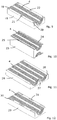
Fig. 1 is a perspective view of a structure wall formed of a number of blocks according to the present invention, -
Fig. 2 is a perspective view from above of one example of a block according to the present invention, -
Fig. 3 is a perspective view from below of the block ofFig. 2 , -
Fig. 4 is a perspective view from above of a further example of a block according to the present invention, -
Fig. 5 is a perspective view from below of a still a further example of a block according to the present invention, -
Fig. 6 is an end view of the block ofFig. 5 , -
Fig. 7 is a perspective view from above of a further example of a block according to the present invention, -
Fig. 8 is a perspective view of a one example of a frame to be used with blocks according to the present invention, and -
Figs. 9-12 are perspective views of yet further examples of blocks according to the present invention. - As used in this description and for ease of description the expressions "upper", "lower", "top", "bottom" and similar expressions are normally in view of the Figs. referred to, or in view of the normal orientation at use. However, a person skilled in the art realises that the blocks of the present invention may have any orientation at use. As used in this description the terms "height", "width" and "thickness" are used in connection with the blocks and the formed wall in directions as indicated with h, w and t, respectively, in
Fig. 2 . - By means of a number of
blocks - In one embodiment the
blocks upper block 1 and onelower block 2 is to be placed at the top and bottom, respectively, of the formed structure. Between the upper andlower blocks intermediate blocks 3 are placed in the structure. Theblocks blocks - The
upper block 1 ofFigs. 2 and 3 has a generally rectangular shape. In the middle of the lower surface of theupper block 1, two central semicircular recesses, as seen in cross section, are formed receiving a number ofpeelable sheets 4 or layers. The semicircular recesses extend all of the thickness of theupper block 1. The upper surface of theupper block 1 is even. On the lower side of the upper block 1 a number ofopenings 5 are placed for co-operation with protruding parts in the form ofbosses 6 of a block placed below theupper block 1 in use. - The
lower block 2 ofFig. 4 has a generally rectangular shape. In the middle of the upper surface of thelower block 2, two semicircular recesses are formed receiving a number ofpeelable sheets 4 or layers. The semicircular recesses extend all of the thickness of thelower block 2. On the upper surface of the lower block 2 a number of protruding parts orbosses 6 are formed. Thebosses 6 are to co-operate withopenings 5 of one or more blocks placed above the lower block in use, to hold the blocks together. - Normally, the lower surface of the
lower block 2 is an even continuous surface, having no openings. - When used with the upper and
lower blocks Figs. 2-4 , theintermediate blocks 3 have bosses and openings for co-operation with theopenings 5 andbosses 6 of theupper blocks 1 andlower blocks 2, respectively. Theintermediate block 3 ofFigs. 5 and 6 has a generally rectangular shape. In the middle of each of the lower and upper surfaces, respectively, of theintermediate block 3, semicircular recesses are formed receiving a number ofpeelable sheets 4 or layers. The semicircular recesses extend all of the thickness of theblock 3. - In the embodiments of
Figs. 5, 6 and7 an alternative form of the parts connecting thedifferent blocks blocks 3, 11 a number ofprotruding parts blocks 3, 11 a number ofcorresponding openings parts openings openings parts blocks - In the embodiment of
Figs. 5-7 the protrudingparts 7 at the corners each has two straight parts forming a right angle, thus, the protrudingparts 7 andcorresponding openings 9 show an L-form in plan view. On two opposite sides of each block further protrudingparts 8 are arranged between the protrudingparts 7 at the corners. Said further protrudingparts 8 are to be received in correspondingopenings 10 at a block to be placed above the block having the further protrudingparts 8. Said further protrudingparts 8 andcorresponding openings 10 have only one straight part. The protrudingparts openings - A person skilled in the art realises that the connection between blocks placed on top of each other may be accomplished in many different ways. For instance the protruding parts and corresponding openings may have other forms than shown.
- All protruding parts on one block and corresponding co-operating parts or openings of an adjacent block have complementary forms, independently of the exact form of the protruding parts and co-operating parts. The protruding parts are received in a tight fit in the co-operating parts. Thus, the blocks are held together by means of the tight fit between the protruding parts and the co-operating parts.
- As indicated in
Fig. 1 the blocks may have different number of recesses receivingpeelable sheets 4. The recesses are evenly distributed on the blocks 1-3, 11. A person skilled in the art realises that the number of recess may vary in principle without limitation. Thus, a block, being an upper, lower or intermediate block, may have one, two, three, four, five etc. recesses on one surface. - By the co-operation through the tight fit between the
bosses 6 and protrudingparts openings - The blocks 1-3, 11 used to form a single wall structure should each have the same height and thickness but may have different widths as indicated above. To form a stable wall structure blocks of different widths are used in such a way that contact surfaces between two separate blocks 1-3, 11 are not placed on a continuous vertical line going through all of the formed wall structure. Such a continuous non-interrupted vertical line will give rows of blocks 1-3, 11 that are not attached to adjacent rows of blocks 1-3, 11.
- The blocks 1-3, 11 may have further features in other embodiments as shown in the simultaneously filed applications entitled "A pipe or Cable Lead-Through having a Part Indicating Compression", "A Module of a Pipe or Cable Lead-Through having Grooves on Opposite Sides", "Modules of Pipe or Cable Lead-Through Sticking Together", "A Pipe or Cable Lead-Through having Modularized Modules", "A Pipe or Cable Lead-Through having Penetrateable Modules", "Lubrication of a Pipe or Cable Lead-Through" and "A Pipe or Cable Lead-Through having Modules with a Dimensioning Function", filed by the applicant of the present application.
- The semicircular recesses of the blocks are placed in such a way that when blocks are put together to form a wall, circular recesses are formed of two semicircular recesses of blocks 1-3, 11 placed on top of each other. In the middle of the
peelable sheets 4 of each circular recess a blind 12 is placed. Theblinds 12 are normally fixed by adhesive to thepeelable sheets 4 on either the upper or lower sides of each block 1-3, 11. The blind 12 is taken away when a cable or pipe is to be received in the recess. The recess may be placed eccentrically in the same way as shown in the simultaneously filed application entitled "Eccentric Part of a Pipe or cable Lead-Through", filed by the applicant of the present application. - The
sheets 4 of each block adhere enough to each other to stick together but at the same time loose enough to be peeled off by hand. The same goes for theblinds 12. - Normally the
sheets 4 are peeled off one by one but it is also possible to peel off a larger number ofsheets 4 at the time. Thesheets 4 are made of an elastic polymeric material. - The sheets may be arranged in many different ways and with different features as reflected in the simultaneously filed applications entitled "A pipe or Cable Lead-Through having Interconnected Layers", "A Pipe or Cable Lead-Through having Layers of Different Thickness", "Cohering Between Layers of a Pipe or Cable Lead-Through" and "Identification of Layers of a Pipe or Cable Lead-Through", filed by the applicant of the present application.
- Often the structure of blocks 1-3, 11 is received inside a frame or the like holding the structure in position and possibly compressing the structure. The tightness of the structure will be improved by compressing. In
Fig. 8 one example of a frame is shown, which frame may be used together with the structure of blocks 1-3, 11. The frame has an upperhorizontal frame beam 13, a lowerhorizontal frame beam 14, a leftvertical frame beam 15 and a rightvertical frame beam 16. The stated positions of the different frame beams 13-16 are with reference toFig. 8 . A person skilled in the art realises that the frame may be mounted in other positions than as showed inFig. 8 . The upperhorizontal frame beam 12 has two through openings at the ends. The trough openings are to receive onefixation screw 17 each. The fixation screws 17 go into onevertical frame beam vertical frame beam horizontal frame beam 13, the lowerhorizontal frame beam 14, the leftvertical frame beam 15 and the rightvertical frame beam 16. The dimension of the frame may be altered, by replacing the horizontal and/or vertical frame beams 13-16 with frame beams of other lengths. In some embodiments (not shown) the blocks adjacent the frame are connected to the frame by means of co-operating protruding parts and openings. Thus, such blocks are connected to the frame in a similar way to the connection between the blocks. - In a further embodiment one or more of the horizontal and/or the vertical frame beams are received movable in relation to the other parts of the frame, thereby the inner dimension of the frame may be varied in a simple way.
- In
Figs. 9-12 further examples of connection between the blocks are shown. A person skilled in the art realises that the exact form of the co-operating parts forming the mutual connection between the blocks may be varied in many ways and that the shown connecting parts may be combined in many different ways. For several of the shown examples the upper and lower blocks are identical. This is achieved in that the blocks are provided with alternating bosses and groves. - In the example of
Fig. 9 ablock 18 is shown. A number ofpeelable sheets 4 are placed in a semicylindrical recess of theblock 18. Theblock 18 has protrudingparts 19 having an L-form in two diagonally opposite corners and two L-formedopenings 20 at the other two corners. Between the protrudingparts 19 andopenings 20, respectively, at the corners further protrudingparts 21 andopenings 22 are placed outside the recess holding thepeelable sheets 4. These latter protrudingparts 21 andopenings 22 have an elongated form. - The
block 23 shown inFig. 10 has a protruding part in the form of arail 24 and a co-operating part in the form of agroove 25 on two opposing sides, which rails 24 andgrooves 25 extend across theblock 23 in the thickness direction t. Therails 24 andgrooves 25 are placed outside a semicylindrical recess receiving a number ofpeelable sheets 4. Therails 24 andgrooves 25 have corresponding cross sections in form of a dovetail. By means of the dovetails twoblocks 23 may be held together firmly in the height h direction of the blocks. Twoconnected blocks 23 are to be slid in relation to each other to connect or disconnect them. A person skilled in the art realises that it is possible to achieve them same effect with rails and grooves of many different cross section forms. - The
block 26 ofFig. 11 has protruding parts orbosses 27 andopenings 28 corresponding with thebosses 5 andopenings 6 of theblocks Figs. 3 and 4 . However, in the embodiment ofFig. 11 theblock 26 has alternatingbosses 27 andopenings 28 on the same side of theblock 26. - The
block 29 ofFig. 12 differs from theblock 20 ofFig. 9 only in the form of the protrudingparts 30 and theopenings 31. In theblock 29 ofFig. 12 the protrudingparts 30 and theopenings 31 all have an elongated form. - Also in the embodiments of
Figs. 9-12 the protruding parts and co-operating parts have complementary forms and are held together in a tight fit. - A person skilled in the art realises that the different connection forms shown in
Figs. 9-12 also could be used in possible connection between blocks and a frame. - In use a cable or pipe may be placed in each circular recess of the structure. If the number of cables or pipes to be received is less than the available recesses the
blinds 12 of the recesses not used are kept in place. When a cable or pipe is to be received in a recess, the blocks 1-3, 11, forming said recess, are separated. Then the blind 12 is taken out and an appropriate number ofsheets 4 are peeled off from respective block 1-3, 11. The number ofsheets 4 peeled off should give an opening normally having an inner diameter being slightly smaller than the outer diameter of the cable or pipe received. As thesheets 4 are made of an elastic material the difference in diameter will be taken up by thesheets 4 remaining in respective block 1-3, 11. In some embodiments the blocks 1-3, 11 are made of an elastic material taking up the difference in diameter. The number of blocks 1-3, 11 used to form a structure of blocks is adapted to the size of an opening in which the structure of blocks is to be received. When all cables or pipes have been placed in the appropriate recesses the blocks are put together to form the structure of blocks, such as a wall. The formed structure of blocks is then pressed into the opening, whereby a tight lead-through is formed for the cables and/or pipes. The structure of blocks 1-3, 11 may be compressed somewhat at installation due to the elasticity of thepeelable sheets 4 of the recesses of the blocks 1-3, 11 or the elasticity of the blocks 1-3, 11. - If the structure of blocks 1-3, 11 is to be received inside a frame of the type shown in
Fig. 8 , horizontal and vertical frame beams 13-16 of appropriate dimensions are chosen. The length of the horizontal frame beams 13, 14 is adapted to the width of the formed structure of blocks 1-3, 11 and the length of the vertical frame beams 15, 16 is adapted to the height of the formed structure of blocks 1-3, 11. When the structure of blocks 1-3, 11 has been placed inside the frame the fixation screws 17 are tightened in order to compress the structure of blocks 1-3, 11. As indicated above thepeelable sheets 4 of each block 1-3, 11 are elastic and a compression given by means of the fixation screws 17 of the frame will enhance the tightening of the cable and/or pipe lead-throughs.
Claims (12)
- A structure formed of a number of blocks (1, 2, 3, 11, 18, 23, 26, 29) having a generally rectangular shape and placed mutually adjacent to each other and on top of each other, which structure forms a cable or pipe transition for one or more cables or pipes, wherein the structure comprises upper blocks (1), lower blocks (2, 11, 18, 26, 29) and intermediate blocks (3, 23) placed between said upper and lower blocks (1, 2, 11, 18, 26, 29), wherein each block (1-3, 11, 18, 23, 26, 29) has at least one recess having a semicircular cross section form placed on one side of the block (1-3, 11, 18, 23, 26, 29) and extended all of the thickness of the block (1-3, 11, 18, 23, 26, 29), wherein each upper block (1) has at least one recess on a lower surface and an even upper surface, wherein each lower block (2, 11, 18, 26, 29) has at least one recess on an upper surface and an even lower surface, the semicircular recess of the blocks (1-3, 11, 18, 23, 26, 29) are placed in such a way that circular recesses are formed of two semicircular recesses when two blocks (1-3, 11, 18, 23, 26, 29) are placed on top of each other, and wherein a number of peelable sheets (4) are placed in the recesses, inside of which peelable sheets a cable or pipe is to be received, characterized in that
each intermediate block (3, 23) has at least one recess on lower and at least one recess on upper surfaces, that the blocks have means for fastening each block to a further block placed above or below the block (1-3, 11, 18, 23, 26, 29), which means are protruding parts (6, 7, 8, 19, 21, 27, 30) at one block (2, 3, 11, 18, 26, 29) and co-operating parts (5, 9, 10, 20, 22, 25, 28, 31) at an opposite block (1, 3, 18, 26, 29), that the protruding parts (6, 7, 8, 19, 21, 27, 30) and co-operating parts (5, 9, 10, 20, 22, 25, 28, 31) have complementary forms, that the protruding parts (6, 7, 8, 19, 21, 27, 30) are received in a tight fit in the co-operating parts (5, 9, 10, 20, 22, 25, 28, 31), and that at least one block (1-3, 11, 18, 23, 26, 29) has another width than the other blocks, whereby the blocks are placed in such a way that contact surfaces between two separate blocks are not placed on a continuous vertical line going through all of the formed structure from the lower surface of the lower blocks (2, 11, 18, 26, 29) to the upper surface of the upper blocks. - The structure of claim 1, wherein a number of said protruding parts (6, 7, 8, 19, 21, 27, 30) at one block (2, 3, 11, 18, 26, 29) co-operates with said co-operating parts formed as openings (5, 9, 10, 20, 22, 28, 31) at another block (1, 3, 18, 26, 29), to fasten two blocks to each other.
- The structure of claim 2, wherein protruding parts (7, 19) placed at corners of a block (3, 11, 21) and openings (9, 20) placed at corners of a block (3, 18) each has two straight parts forming a right angle, giving the protruding parts (7, 19) and openings (9, 20) an L-form in plan view, and wherein protruding parts (8, 21) and corresponding openings (10, 22) placed between the protruding parts (7, 19) and openings (9, 20), respectively, at the corners have an elongated form.
- The structure of claim 2, wherein the protruding parts (30) and the openings (31) have an elongated form.
- The structure of claim 1, wherein the protruding parts are rails (24) on one block (23) co-operating with grooves (25) of another block (23), which rails (24) and grooves (25) extends all of the thickness of the block (23).
- The structure of claim 5, wherein the rails (24) and grooves (25) have a dovetail form in cross section.
- The structure of any of the previous claims, wherein the peelable sheets (4) adhere to each other loose enough for separate sheets to be peeled off by hand.
- Arrangement comprising the structure of any of the preceding claims and a frame, wherein the structured is placed inside a frame.
- The arrangement of claim 8, wherein the frame is formed of an upper horizontal frame beam (13), a lower horizontal frame beam (14), a left vertical frame beam (15) and a right vertical frame beam (16).
- The arrangement of claim 9, wherein the frame beams (13-16) are fixed to each other by means of fixation screws.
- The arrangement of claim 9, wherein one or more of the horizontal and/or the vertical frame beams (13-16) are received movable in relation to the other frame beams of the frame.
- The arrangement according to any of the claims 8-11, wherein the frame is attached to the blocks (1-3, 11, 18, 23, 26, 29) by means of protruding parts on either the blocks or the frame and cooperating parts of the frame and blocks, respectively.
Applications Claiming Priority (2)
| Application Number | Priority Date | Filing Date | Title |
|---|---|---|---|
| SE0950039A SE533467C2 (en) | 2009-02-04 | 2009-02-04 | Pipe or cable entry block |
| PCT/SE2010/050118 WO2010090584A1 (en) | 2009-02-04 | 2010-02-02 | Pipe or cable lead-through blocks |
Publications (3)
| Publication Number | Publication Date |
|---|---|
| EP2394085A1 EP2394085A1 (en) | 2011-12-14 |
| EP2394085A4 EP2394085A4 (en) | 2017-03-08 |
| EP2394085B1 true EP2394085B1 (en) | 2020-01-15 |
Family
ID=42542294
Family Applications (1)
| Application Number | Title | Priority Date | Filing Date |
|---|---|---|---|
| EP10738815.9A Active EP2394085B1 (en) | 2009-02-04 | 2010-02-02 | Structure formed of multiple pipe or cable lead-through blocks |
Country Status (11)
| Country | Link |
|---|---|
| US (1) | US20120032036A1 (en) |
| EP (1) | EP2394085B1 (en) |
| KR (1) | KR20110126634A (en) |
| CN (1) | CN102292586A (en) |
| AU (1) | AU2010211406A1 (en) |
| BR (1) | BRMU9002610U2 (en) |
| MY (1) | MY160854A (en) |
| RU (1) | RU118801U1 (en) |
| SE (1) | SE533467C2 (en) |
| SG (1) | SG173120A1 (en) |
| WO (1) | WO2010090584A1 (en) |
Families Citing this family (11)
| Publication number | Priority date | Publication date | Assignee | Title |
|---|---|---|---|---|
| SE533541C2 (en) * | 2009-02-04 | 2010-10-19 | Roxtec Ab | Lubrication of a pipe or cable entry |
| USD715744S1 (en) | 2011-03-11 | 2014-10-21 | Roxtec Ab | Cable and pipe penetration seal |
| BRPI1106760A2 (en) * | 2011-10-28 | 2013-11-05 | Wladimir De Freitas Silvestre | PIPE SUPPORT AND APPLICATION METHOD OF A PIPE SUPPORT IN A SLAB |
| US9441367B2 (en) | 2011-10-28 | 2016-09-13 | Wladimir de Freitas Silvestre | Supporting element for pipes in buildings and application method of a pipe supporting element in a flagstone |
| US9142946B2 (en) * | 2013-06-27 | 2015-09-22 | Caterpillar Inc. | Cable retention system |
| CN104613253A (en) * | 2015-01-21 | 2015-05-13 | 柳州市颖航汽配有限公司 | Automobile control wire sheath |
| WO2017046064A1 (en) * | 2015-09-14 | 2017-03-23 | CommScope Connectivity Belgium BVBA | Sealing block arrangements for enclosures |
| CA169010S (en) * | 2015-12-18 | 2017-02-22 | Roxtec Ab | Multi module for flat cables |
| US10309553B1 (en) | 2017-11-16 | 2019-06-04 | Cnh Industrial America Llc | Hose clamp assembly |
| RU183979U1 (en) * | 2018-06-21 | 2018-10-11 | Федеральное государственное автономное образовательное учреждение высшего образования "Сибирский федеральный университет" | DESIGN OF INPUT PIPELINE SYSTEM IN THE BUILDING |
| SE545653C2 (en) * | 2021-06-08 | 2023-11-28 | Roxtec Ab | A transit device for leading one or more cables and/or pipes through an opening in a partition |
Family Cites Families (20)
| Publication number | Priority date | Publication date | Assignee | Title |
|---|---|---|---|---|
| US3282544A (en) * | 1963-03-11 | 1966-11-01 | Lyckeaborgs Bruk Ab | Tight lead-through inlet frame device for electrical lines |
| US4199070A (en) * | 1977-02-15 | 1980-04-22 | Magnussen Robert O Jr | Modular rack |
| US4099626A (en) * | 1977-02-15 | 1978-07-11 | Magnussen Jr Robert O | Modular rack |
| SE461887B (en) * | 1986-04-28 | 1990-04-02 | Lycab Ab | TENSION DEVICE FOR A CABLE PIPE |
| DE8620941U1 (en) | 1986-08-04 | 1986-11-20 | Thyssen Plastik Anger KG, 8000 München | Connecting element |
| US5783776A (en) * | 1991-10-29 | 1998-07-21 | O-Z Gedney Company Llc | Electrical cable penetration seal with compliant module |
| DE9414666U1 (en) * | 1994-03-16 | 1995-08-24 | Murrplastik Systemtechnik GmbH, 71570 Oppenweiler | Cable entry system |
| US5566269A (en) * | 1995-05-30 | 1996-10-15 | The Whitaker Corporation | Strain relieving holder for optical fiber cable |
| JP2710767B2 (en) * | 1995-10-11 | 1998-02-10 | 北川工業株式会社 | Cable retainer |
| DE29713557U1 (en) * | 1997-07-30 | 1997-09-25 | Schlicksupp, Hans J., 67059 Ludwigshafen | Device for passing cables through openings in walls |
| SE0200158L (en) | 2002-01-22 | 2003-02-25 | Roxtec Int Ab | Frame, for cable entry or similar, provided with a breakable cover |
| SE526243C2 (en) * | 2003-12-12 | 2005-08-02 | Roxtec Ab | Feed-through device for cables or pipes |
| US20050173597A1 (en) * | 2004-02-11 | 2005-08-11 | Patterson Ventilation Co., Inc. | Pipe and cable support apparatus and method |
| US20100215205A1 (en) * | 2005-12-13 | 2010-08-26 | Pioneer Corporation Pioneer Display Products Corporation | Audio Playback Apparatus and Stand for Display Apparatus |
| SE0600367L (en) * | 2006-02-17 | 2007-08-18 | Roxtec Ab | Cable restraint system |
| TW200810265A (en) | 2006-05-31 | 2008-02-16 | Roxtec Ab | A plug unit for a cable entry |
| CN101154798B (en) * | 2006-09-30 | 2012-03-21 | 拉普工程公司 | Cable feed-through device and cable feed-through system |
| SE531217C2 (en) * | 2007-05-29 | 2009-01-20 | Roxtec Ab | Cable entry |
| US7922012B2 (en) * | 2008-07-24 | 2011-04-12 | Power Bus Way Ltd. | Cable tray |
| US20100258687A1 (en) * | 2009-04-10 | 2010-10-14 | Nedshipgroup S.A. | Pipe Securing System, Pipe Receiving Element, and Use Thereof |
-
2009
- 2009-02-04 SE SE0950039A patent/SE533467C2/en not_active IP Right Cessation
-
2010
- 2010-02-02 MY MYPI2011003461A patent/MY160854A/en unknown
- 2010-02-02 RU RU2011131144/07U patent/RU118801U1/en active
- 2010-02-02 KR KR1020117019729A patent/KR20110126634A/en not_active Ceased
- 2010-02-02 WO PCT/SE2010/050118 patent/WO2010090584A1/en not_active Ceased
- 2010-02-02 BR BRMU9002610-1U patent/BRMU9002610U2/en not_active Application Discontinuation
- 2010-02-02 US US13/138,154 patent/US20120032036A1/en not_active Abandoned
- 2010-02-02 AU AU2010211406A patent/AU2010211406A1/en not_active Abandoned
- 2010-02-02 CN CN2010800054707A patent/CN102292586A/en active Pending
- 2010-02-02 EP EP10738815.9A patent/EP2394085B1/en active Active
- 2010-02-02 SG SG2011053428A patent/SG173120A1/en unknown
Non-Patent Citations (1)
| Title |
|---|
| None * |
Also Published As
| Publication number | Publication date |
|---|---|
| AU2010211406A1 (en) | 2011-08-18 |
| MY160854A (en) | 2017-03-31 |
| EP2394085A4 (en) | 2017-03-08 |
| KR20110126634A (en) | 2011-11-23 |
| BRMU9002610U2 (en) | 2013-12-17 |
| CN102292586A (en) | 2011-12-21 |
| SE533467C2 (en) | 2010-10-05 |
| EP2394085A1 (en) | 2011-12-14 |
| RU118801U1 (en) | 2012-07-27 |
| US20120032036A1 (en) | 2012-02-09 |
| WO2010090584A1 (en) | 2010-08-12 |
| SE0950039A1 (en) | 2010-08-05 |
| SG173120A1 (en) | 2011-08-29 |
Similar Documents
| Publication | Publication Date | Title |
|---|---|---|
| US20120032036A1 (en) | Pipe or cable lead-through blocks | |
| EP2245713B1 (en) | Transition frame with integrated compression unit | |
| EP2394340B2 (en) | Sealing system | |
| KR200475438Y1 (en) | Modules of a pipe or cable lead-through having alternating geometry | |
| EP2348240B1 (en) | Sealing system | |
| US8563877B2 (en) | Frame | |
| EP2394084B1 (en) | Modules of pipe or cable lead-throughs sticking together | |
| US11489324B2 (en) | Extension frame | |
| EP1820245B1 (en) | Frame and method of comprising one or more elastic modules for cable entries, pipe penetrations or the like. | |
| WO2010090583A1 (en) | A module of a pipe or cable lead-through having grooves on opposite sides | |
| KR200450518Y1 (en) | frame | |
| WO2025127983A1 (en) | A transit system for leading cables and pipes through a partition, use of an anchoring element for such a transit system and a method for providing the transit system | |
| KR20260061269A (en) | A stay plate for securing a sealing module in a transit system, the use of the stay plate, a transit system including such a stay plate, and the use thereof. | |
| KR20100008059U (en) | A pipe or cable lead-through having layers of alternating geometry | |
| WO2025063874A1 (en) | A stayplate for holding sealing modules in a transit system, use of a stayplate, transit system comprising such a stayplate and use thereof | |
| WO2025095834A1 (en) | A sealing module, a use thereof and a transit system comprising such a sealing module |
Legal Events
| Date | Code | Title | Description |
|---|---|---|---|
| PUAI | Public reference made under article 153(3) epc to a published international application that has entered the european phase |
Free format text: ORIGINAL CODE: 0009012 |
|
| 17P | Request for examination filed |
Effective date: 20110830 |
|
| AK | Designated contracting states |
Kind code of ref document: A1 Designated state(s): AT BE BG CH CY CZ DE DK EE ES FI FR GB GR HR HU IE IS IT LI LT LU LV MC MK MT NL NO PL PT RO SE SI SK SM TR |
|
| DAX | Request for extension of the european patent (deleted) | ||
| RA4 | Supplementary search report drawn up and despatched (corrected) |
Effective date: 20170207 |
|
| RIC1 | Information provided on ipc code assigned before grant |
Ipc: F16L 5/02 20060101ALI20170201BHEP Ipc: H02G 3/22 20060101AFI20170201BHEP |
|
| STAA | Information on the status of an ep patent application or granted ep patent |
Free format text: STATUS: EXAMINATION IS IN PROGRESS |
|
| 17Q | First examination report despatched |
Effective date: 20190314 |
|
| REG | Reference to a national code |
Ref country code: DE Ref legal event code: R079 Ref document number: 602010062809 Country of ref document: DE Free format text: PREVIOUS MAIN CLASS: F16L0005020000 Ipc: H02G0003220000 |
|
| GRAP | Despatch of communication of intention to grant a patent |
Free format text: ORIGINAL CODE: EPIDOSNIGR1 |
|
| STAA | Information on the status of an ep patent application or granted ep patent |
Free format text: STATUS: GRANT OF PATENT IS INTENDED |
|
| RIC1 | Information provided on ipc code assigned before grant |
Ipc: F16L 5/08 20060101ALI20190730BHEP Ipc: H02G 3/22 20060101AFI20190730BHEP |
|
| INTG | Intention to grant announced |
Effective date: 20190829 |
|
| GRAS | Grant fee paid |
Free format text: ORIGINAL CODE: EPIDOSNIGR3 |
|
| GRAA | (expected) grant |
Free format text: ORIGINAL CODE: 0009210 |
|
| STAA | Information on the status of an ep patent application or granted ep patent |
Free format text: STATUS: THE PATENT HAS BEEN GRANTED |
|
| AK | Designated contracting states |
Kind code of ref document: B1 Designated state(s): AT BE BG CH CY CZ DE DK EE ES FI FR GB GR HR HU IE IS IT LI LT LU LV MC MK MT NL NO PL PT RO SE SI SK SM TR |
|
| REG | Reference to a national code |
Ref country code: CH Ref legal event code: EP Ref country code: GB Ref legal event code: FG4D |
|
| REG | Reference to a national code |
Ref country code: IE Ref legal event code: FG4D |
|
| REG | Reference to a national code |
Ref country code: DE Ref legal event code: R096 Ref document number: 602010062809 Country of ref document: DE |
|
| REG | Reference to a national code |
Ref country code: AT Ref legal event code: REF Ref document number: 1226005 Country of ref document: AT Kind code of ref document: T Effective date: 20200215 |
|
| REG | Reference to a national code |
Ref country code: NL Ref legal event code: MP Effective date: 20200115 |
|
| REG | Reference to a national code |
Ref country code: LT Ref legal event code: MG4D |
|
| PG25 | Lapsed in a contracting state [announced via postgrant information from national office to epo] |
Ref country code: FI Free format text: LAPSE BECAUSE OF FAILURE TO SUBMIT A TRANSLATION OF THE DESCRIPTION OR TO PAY THE FEE WITHIN THE PRESCRIBED TIME-LIMIT Effective date: 20200115 Ref country code: PT Free format text: LAPSE BECAUSE OF FAILURE TO SUBMIT A TRANSLATION OF THE DESCRIPTION OR TO PAY THE FEE WITHIN THE PRESCRIBED TIME-LIMIT Effective date: 20200607 Ref country code: NO Free format text: LAPSE BECAUSE OF FAILURE TO SUBMIT A TRANSLATION OF THE DESCRIPTION OR TO PAY THE FEE WITHIN THE PRESCRIBED TIME-LIMIT Effective date: 20200415 Ref country code: NL Free format text: LAPSE BECAUSE OF FAILURE TO SUBMIT A TRANSLATION OF THE DESCRIPTION OR TO PAY THE FEE WITHIN THE PRESCRIBED TIME-LIMIT Effective date: 20200115 |
|
| PG25 | Lapsed in a contracting state [announced via postgrant information from national office to epo] |
Ref country code: HR Free format text: LAPSE BECAUSE OF FAILURE TO SUBMIT A TRANSLATION OF THE DESCRIPTION OR TO PAY THE FEE WITHIN THE PRESCRIBED TIME-LIMIT Effective date: 20200115 Ref country code: GR Free format text: LAPSE BECAUSE OF FAILURE TO SUBMIT A TRANSLATION OF THE DESCRIPTION OR TO PAY THE FEE WITHIN THE PRESCRIBED TIME-LIMIT Effective date: 20200416 Ref country code: LV Free format text: LAPSE BECAUSE OF FAILURE TO SUBMIT A TRANSLATION OF THE DESCRIPTION OR TO PAY THE FEE WITHIN THE PRESCRIBED TIME-LIMIT Effective date: 20200115 Ref country code: BG Free format text: LAPSE BECAUSE OF FAILURE TO SUBMIT A TRANSLATION OF THE DESCRIPTION OR TO PAY THE FEE WITHIN THE PRESCRIBED TIME-LIMIT Effective date: 20200415 Ref country code: SE Free format text: LAPSE BECAUSE OF FAILURE TO SUBMIT A TRANSLATION OF THE DESCRIPTION OR TO PAY THE FEE WITHIN THE PRESCRIBED TIME-LIMIT Effective date: 20200115 Ref country code: IS Free format text: LAPSE BECAUSE OF FAILURE TO SUBMIT A TRANSLATION OF THE DESCRIPTION OR TO PAY THE FEE WITHIN THE PRESCRIBED TIME-LIMIT Effective date: 20200515 |
|
| REG | Reference to a national code |
Ref country code: DE Ref legal event code: R119 Ref document number: 602010062809 Country of ref document: DE |
|
| REG | Reference to a national code |
Ref country code: CH Ref legal event code: PL |
|
| REG | Reference to a national code |
Ref country code: BE Ref legal event code: MM Effective date: 20200229 |
|
| PG25 | Lapsed in a contracting state [announced via postgrant information from national office to epo] |
Ref country code: CZ Free format text: LAPSE BECAUSE OF FAILURE TO SUBMIT A TRANSLATION OF THE DESCRIPTION OR TO PAY THE FEE WITHIN THE PRESCRIBED TIME-LIMIT Effective date: 20200115 Ref country code: ES Free format text: LAPSE BECAUSE OF FAILURE TO SUBMIT A TRANSLATION OF THE DESCRIPTION OR TO PAY THE FEE WITHIN THE PRESCRIBED TIME-LIMIT Effective date: 20200115 Ref country code: SK Free format text: LAPSE BECAUSE OF FAILURE TO SUBMIT A TRANSLATION OF THE DESCRIPTION OR TO PAY THE FEE WITHIN THE PRESCRIBED TIME-LIMIT Effective date: 20200115 Ref country code: MC Free format text: LAPSE BECAUSE OF FAILURE TO SUBMIT A TRANSLATION OF THE DESCRIPTION OR TO PAY THE FEE WITHIN THE PRESCRIBED TIME-LIMIT Effective date: 20200115 Ref country code: SM Free format text: LAPSE BECAUSE OF FAILURE TO SUBMIT A TRANSLATION OF THE DESCRIPTION OR TO PAY THE FEE WITHIN THE PRESCRIBED TIME-LIMIT Effective date: 20200115 Ref country code: EE Free format text: LAPSE BECAUSE OF FAILURE TO SUBMIT A TRANSLATION OF THE DESCRIPTION OR TO PAY THE FEE WITHIN THE PRESCRIBED TIME-LIMIT Effective date: 20200115 Ref country code: LU Free format text: LAPSE BECAUSE OF NON-PAYMENT OF DUE FEES Effective date: 20200202 Ref country code: DK Free format text: LAPSE BECAUSE OF FAILURE TO SUBMIT A TRANSLATION OF THE DESCRIPTION OR TO PAY THE FEE WITHIN THE PRESCRIBED TIME-LIMIT Effective date: 20200115 Ref country code: LT Free format text: LAPSE BECAUSE OF FAILURE TO SUBMIT A TRANSLATION OF THE DESCRIPTION OR TO PAY THE FEE WITHIN THE PRESCRIBED TIME-LIMIT Effective date: 20200115 Ref country code: RO Free format text: LAPSE BECAUSE OF FAILURE TO SUBMIT A TRANSLATION OF THE DESCRIPTION OR TO PAY THE FEE WITHIN THE PRESCRIBED TIME-LIMIT Effective date: 20200115 |
|
| REG | Reference to a national code |
Ref country code: AT Ref legal event code: MK05 Ref document number: 1226005 Country of ref document: AT Kind code of ref document: T Effective date: 20200115 |
|
| PLBE | No opposition filed within time limit |
Free format text: ORIGINAL CODE: 0009261 |
|
| STAA | Information on the status of an ep patent application or granted ep patent |
Free format text: STATUS: NO OPPOSITION FILED WITHIN TIME LIMIT |
|
| PG25 | Lapsed in a contracting state [announced via postgrant information from national office to epo] |
Ref country code: LI Free format text: LAPSE BECAUSE OF NON-PAYMENT OF DUE FEES Effective date: 20200229 Ref country code: CH Free format text: LAPSE BECAUSE OF NON-PAYMENT OF DUE FEES Effective date: 20200229 |
|
| 26N | No opposition filed |
Effective date: 20201016 |
|
| PG25 | Lapsed in a contracting state [announced via postgrant information from national office to epo] |
Ref country code: FR Free format text: LAPSE BECAUSE OF NON-PAYMENT OF DUE FEES Effective date: 20200315 Ref country code: IT Free format text: LAPSE BECAUSE OF FAILURE TO SUBMIT A TRANSLATION OF THE DESCRIPTION OR TO PAY THE FEE WITHIN THE PRESCRIBED TIME-LIMIT Effective date: 20200115 Ref country code: AT Free format text: LAPSE BECAUSE OF FAILURE TO SUBMIT A TRANSLATION OF THE DESCRIPTION OR TO PAY THE FEE WITHIN THE PRESCRIBED TIME-LIMIT Effective date: 20200115 Ref country code: DE Free format text: LAPSE BECAUSE OF NON-PAYMENT OF DUE FEES Effective date: 20200901 Ref country code: IE Free format text: LAPSE BECAUSE OF NON-PAYMENT OF DUE FEES Effective date: 20200202 |
|
| PG25 | Lapsed in a contracting state [announced via postgrant information from national office to epo] |
Ref country code: PL Free format text: LAPSE BECAUSE OF FAILURE TO SUBMIT A TRANSLATION OF THE DESCRIPTION OR TO PAY THE FEE WITHIN THE PRESCRIBED TIME-LIMIT Effective date: 20200115 Ref country code: SI Free format text: LAPSE BECAUSE OF FAILURE TO SUBMIT A TRANSLATION OF THE DESCRIPTION OR TO PAY THE FEE WITHIN THE PRESCRIBED TIME-LIMIT Effective date: 20200115 Ref country code: BE Free format text: LAPSE BECAUSE OF NON-PAYMENT OF DUE FEES Effective date: 20200229 |
|
| GBPC | Gb: european patent ceased through non-payment of renewal fee |
Effective date: 20200415 |
|
| PG25 | Lapsed in a contracting state [announced via postgrant information from national office to epo] |
Ref country code: GB Free format text: LAPSE BECAUSE OF NON-PAYMENT OF DUE FEES Effective date: 20200415 |
|
| PG25 | Lapsed in a contracting state [announced via postgrant information from national office to epo] |
Ref country code: TR Free format text: LAPSE BECAUSE OF FAILURE TO SUBMIT A TRANSLATION OF THE DESCRIPTION OR TO PAY THE FEE WITHIN THE PRESCRIBED TIME-LIMIT Effective date: 20200115 Ref country code: MT Free format text: LAPSE BECAUSE OF FAILURE TO SUBMIT A TRANSLATION OF THE DESCRIPTION OR TO PAY THE FEE WITHIN THE PRESCRIBED TIME-LIMIT Effective date: 20200115 Ref country code: CY Free format text: LAPSE BECAUSE OF FAILURE TO SUBMIT A TRANSLATION OF THE DESCRIPTION OR TO PAY THE FEE WITHIN THE PRESCRIBED TIME-LIMIT Effective date: 20200115 |
|
| PG25 | Lapsed in a contracting state [announced via postgrant information from national office to epo] |
Ref country code: MK Free format text: LAPSE BECAUSE OF FAILURE TO SUBMIT A TRANSLATION OF THE DESCRIPTION OR TO PAY THE FEE WITHIN THE PRESCRIBED TIME-LIMIT Effective date: 20200115 |