EP2393743B1 - Infeed system - Google Patents
Infeed system Download PDFInfo
- Publication number
- EP2393743B1 EP2393743B1 EP10739040.3A EP10739040A EP2393743B1 EP 2393743 B1 EP2393743 B1 EP 2393743B1 EP 10739040 A EP10739040 A EP 10739040A EP 2393743 B1 EP2393743 B1 EP 2393743B1
- Authority
- EP
- European Patent Office
- Prior art keywords
- infeed
- fanfold
- raw material
- wheel
- converting
- Prior art date
- Legal status (The legal status is an assumption and is not a legal conclusion. Google has not performed a legal analysis and makes no representation as to the accuracy of the status listed.)
- Active
Links
- 239000000463 material Substances 0.000 claims description 104
- 239000002994 raw material Substances 0.000 claims description 95
- 230000007246 mechanism Effects 0.000 claims description 55
- 238000004806 packaging method and process Methods 0.000 claims description 21
- 230000006870 function Effects 0.000 claims description 8
- 230000008859 change Effects 0.000 claims description 5
- 238000006243 chemical reaction Methods 0.000 claims description 2
- 239000005022 packaging material Substances 0.000 description 63
- 239000010410 layer Substances 0.000 description 35
- 238000000034 method Methods 0.000 description 16
- 239000011248 coating agent Substances 0.000 description 9
- 238000000576 coating method Methods 0.000 description 9
- 230000008569 process Effects 0.000 description 7
- 230000033001 locomotion Effects 0.000 description 5
- 238000004519 manufacturing process Methods 0.000 description 5
- 239000002131 composite material Substances 0.000 description 4
- 229910052751 metal Inorganic materials 0.000 description 4
- 239000002184 metal Substances 0.000 description 4
- 239000004033 plastic Substances 0.000 description 4
- 229920003023 plastic Polymers 0.000 description 4
- 229910045601 alloy Inorganic materials 0.000 description 3
- 239000000956 alloy Substances 0.000 description 3
- 239000007769 metal material Substances 0.000 description 3
- 150000002739 metals Chemical class 0.000 description 3
- 239000000123 paper Substances 0.000 description 3
- OKTJSMMVPCPJKN-UHFFFAOYSA-N Carbon Chemical compound [C] OKTJSMMVPCPJKN-UHFFFAOYSA-N 0.000 description 2
- 229910052799 carbon Inorganic materials 0.000 description 2
- 238000005520 cutting process Methods 0.000 description 2
- 230000000694 effects Effects 0.000 description 2
- 238000005516 engineering process Methods 0.000 description 2
- 230000005484 gravity Effects 0.000 description 2
- 230000004048 modification Effects 0.000 description 2
- 238000012986 modification Methods 0.000 description 2
- 239000011368 organic material Substances 0.000 description 2
- 238000005240 physical vapour deposition Methods 0.000 description 2
- 239000002356 single layer Substances 0.000 description 2
- 239000002023 wood Substances 0.000 description 2
- XMWRBQBLMFGWIX-UHFFFAOYSA-N C60 fullerene Chemical compound C12=C3C(C4=C56)=C7C8=C5C5=C9C%10=C6C6=C4C1=C1C4=C6C6=C%10C%10=C9C9=C%11C5=C8C5=C8C7=C3C3=C7C2=C1C1=C2C4=C6C4=C%10C6=C9C9=C%11C5=C5C8=C3C3=C7C1=C1C2=C4C6=C2C9=C5C3=C12 XMWRBQBLMFGWIX-UHFFFAOYSA-N 0.000 description 1
- 229910000831 Steel Inorganic materials 0.000 description 1
- 239000004809 Teflon Substances 0.000 description 1
- 229920006362 Teflon® Polymers 0.000 description 1
- RTAQQCXQSZGOHL-UHFFFAOYSA-N Titanium Chemical compound [Ti] RTAQQCXQSZGOHL-UHFFFAOYSA-N 0.000 description 1
- 230000009471 action Effects 0.000 description 1
- 230000004075 alteration Effects 0.000 description 1
- 229910052782 aluminium Inorganic materials 0.000 description 1
- XAGFODPZIPBFFR-UHFFFAOYSA-N aluminium Chemical compound [Al] XAGFODPZIPBFFR-UHFFFAOYSA-N 0.000 description 1
- 238000000429 assembly Methods 0.000 description 1
- 230000000712 assembly Effects 0.000 description 1
- 230000004888 barrier function Effects 0.000 description 1
- 238000005452 bending Methods 0.000 description 1
- 230000008901 benefit Effects 0.000 description 1
- 230000005540 biological transmission Effects 0.000 description 1
- 239000011111 cardboard Substances 0.000 description 1
- 238000010276 construction Methods 0.000 description 1
- -1 corrugated board Substances 0.000 description 1
- 238000006073 displacement reaction Methods 0.000 description 1
- 239000004744 fabric Substances 0.000 description 1
- 239000012530 fluid Substances 0.000 description 1
- 239000000314 lubricant Substances 0.000 description 1
- CWQXQMHSOZUFJS-UHFFFAOYSA-N molybdenum disulfide Chemical compound S=[Mo]=S CWQXQMHSOZUFJS-UHFFFAOYSA-N 0.000 description 1
- 239000003973 paint Substances 0.000 description 1
- 239000011087 paperboard Substances 0.000 description 1
- 239000000843 powder Substances 0.000 description 1
- 239000007787 solid Substances 0.000 description 1
- 239000010935 stainless steel Substances 0.000 description 1
- 229910001220 stainless steel Inorganic materials 0.000 description 1
- 239000010959 steel Substances 0.000 description 1
- 239000000126 substance Substances 0.000 description 1
- 239000010936 titanium Substances 0.000 description 1
- 229910052719 titanium Inorganic materials 0.000 description 1
- 230000007704 transition Effects 0.000 description 1
- 229920001221 xylan Polymers 0.000 description 1
- 150000004823 xylans Chemical class 0.000 description 1
Images


Classifications
-
- B—PERFORMING OPERATIONS; TRANSPORTING
- B65—CONVEYING; PACKING; STORING; HANDLING THIN OR FILAMENTARY MATERIAL
- B65H—HANDLING THIN OR FILAMENTARY MATERIAL, e.g. SHEETS, WEBS, CABLES
- B65H16/00—Unwinding, paying-out webs
-
- B—PERFORMING OPERATIONS; TRANSPORTING
- B31—MAKING ARTICLES OF PAPER, CARDBOARD OR MATERIAL WORKED IN A MANNER ANALOGOUS TO PAPER; WORKING PAPER, CARDBOARD OR MATERIAL WORKED IN A MANNER ANALOGOUS TO PAPER
- B31B—MAKING CONTAINERS OF PAPER, CARDBOARD OR MATERIAL WORKED IN A MANNER ANALOGOUS TO PAPER
- B31B50/00—Making rigid or semi-rigid containers, e.g. boxes or cartons
- B31B50/02—Feeding or positioning sheets, blanks or webs
- B31B50/04—Feeding sheets or blanks
- B31B50/06—Feeding sheets or blanks from stacks
- B31B50/066—Feeding sheets or blanks from stacks from above a magazine
-
- B—PERFORMING OPERATIONS; TRANSPORTING
- B31—MAKING ARTICLES OF PAPER, CARDBOARD OR MATERIAL WORKED IN A MANNER ANALOGOUS TO PAPER; WORKING PAPER, CARDBOARD OR MATERIAL WORKED IN A MANNER ANALOGOUS TO PAPER
- B31B—MAKING CONTAINERS OF PAPER, CARDBOARD OR MATERIAL WORKED IN A MANNER ANALOGOUS TO PAPER
- B31B50/00—Making rigid or semi-rigid containers, e.g. boxes or cartons
- B31B50/02—Feeding or positioning sheets, blanks or webs
- B31B50/10—Feeding or positioning webs
-
- B—PERFORMING OPERATIONS; TRANSPORTING
- B65—CONVEYING; PACKING; STORING; HANDLING THIN OR FILAMENTARY MATERIAL
- B65B—MACHINES, APPARATUS OR DEVICES FOR, OR METHODS OF, PACKAGING ARTICLES OR MATERIALS; UNPACKING
- B65B2210/00—Specific aspects of the packaging machine
- B65B2210/04—Customised on demand packaging by determining a specific characteristic, e.g. shape or height, of articles or material to be packaged and selecting, creating or adapting a packaging accordingly, e.g. making a carton starting from web material
-
- B—PERFORMING OPERATIONS; TRANSPORTING
- B65—CONVEYING; PACKING; STORING; HANDLING THIN OR FILAMENTARY MATERIAL
- B65H—HANDLING THIN OR FILAMENTARY MATERIAL, e.g. SHEETS, WEBS, CABLES
- B65H2404/00—Parts for transporting or guiding the handled material
- B65H2404/10—Rollers
- B65H2404/11—Details of cross-section or profile
- B65H2404/111—Details of cross-section or profile shape
- B65H2404/1116—Polygonal cross-section
-
- B—PERFORMING OPERATIONS; TRANSPORTING
- B65—CONVEYING; PACKING; STORING; HANDLING THIN OR FILAMENTARY MATERIAL
- B65H—HANDLING THIN OR FILAMENTARY MATERIAL, e.g. SHEETS, WEBS, CABLES
- B65H2701/00—Handled material; Storage means
- B65H2701/10—Handled articles or webs
- B65H2701/18—Form of handled article or web
- B65H2701/182—Piled package
- B65H2701/1824—Web material folded in zig-zag form
-
- B—PERFORMING OPERATIONS; TRANSPORTING
- B65—CONVEYING; PACKING; STORING; HANDLING THIN OR FILAMENTARY MATERIAL
- B65H—HANDLING THIN OR FILAMENTARY MATERIAL, e.g. SHEETS, WEBS, CABLES
- B65H2801/00—Application field
- B65H2801/81—Packaging machines
Definitions
- Exemplary embodiments of the invention relate to apparatus, systems, devices, and methods for feeding and guiding materials through a converting machine. More particularly, example embodiments relate to an infeed system usable for feeding fanfold packaging materials into a converting machine that produces packaging templates from the packaging materials.
- the automating of processes has long been a goal of industrialized society, and in virtually any industry in which a product is produced, some type of automated process is likely to be used. Oftentimes, the automated process may make use of modern technological advances that are combined into one or more automated machines that perform functions used to produce a product.
- the product produced by the automated machine may itself make use of raw materials. Such materials may themselves be loaded, provided, or otherwise introduced into the automated machine using an automated process, or such loading may be manual. Particularly where the loading is performed using an automated process, the raw materials may be positioned near the machine to facilitate loading.
- boxes and other types of packaging may be formed out of paper based products (e.g., corrugated board), and an automated machine may be programmed to use one or more available tools to perform a number of different functions on the corrugated board.
- the corrugated board When loaded into the packaging machine, the corrugated board may be cut, scored, perforated, creased, folded, taped, or otherwise manipulated to form a box of virtually any shape and size, or formed into a template that may later be assembled into a box.
- a converting machine can be found in U.S. Patent No.
- 7,100,811 which is considered to represent the closest prior art and which may use various laterally spaced paths, so that multiple lines of packaging templates can be individually or simultaneously produced.
- the converting machine starts with a raw form of corrugated board (e.g., fanfold corrugated board in one or more separate feed paths) and converts the raw form into a template form that may then be assembled into a box or other type of package.
- a converting machine that produces packaging templates may thus produce the packaging templates only after the corrugated board or other packaging material is introduced into the machine.
- Conventional fanfold configurations use stacks of multiple layers of packaging material. Each layer is approximately the same size and has pre-existing fanfold score lines at each end to separate the layers and allow the fanfold material to stack on top of itself.
- the raw fanfold board may be stacked in a loading position proximate the converting machine.
- conventional converting machines utilize an infeed wheel to draw the fanfold into the converting machine.
- Conventional infeed wheels correspond to the dimensions of the fanfold score lines.
- fanfold material may have score lines that are (1.21m) (forty-eight inches) apart. Therefore conventional converting machines can use an infeed wheel having corners that are 1.21m (forty-eight inches) apart.
- Such infeed wheels that match the length of the fanfold material are specifically designed to avoid creasing the layers of fanfold material between the score lines as the additional creases have been seen as reducing the aesthetic appeal of the produced box template, and possibly the structural integrity.
- the infeed wheels may have a large size.
- the stack of raw materials must be placed further away from the converting machine, thus creating a large machine footprint.
- space is occupied that may otherwise be valuable and usable for other operations, and higher overhead clearance may be needed.
- conventional infeed guides are designed to use the pre-existing score lines on the fanfold
- conventional infeed guides are designed with a large radius to accommodate the turning of the fanfold from the infeed wheel into the converting machine in a manner that does not cause the fanfold to fold or bend between the predefined score lines on the edges of the stack of fanfold.
- infeed guide produces a larger overall size of the converting machine which, in turn, also requires more space. Furthermore, because of the large size, conventional infeed wheels are more expensive to produce as they result in higher material, handling and tooling costs, thus increasing the cost of the converting machine as a whole.
- the space between the stack of fanfold and the converting machine may allow space for an inattentive operator to walk between the stack of fanfold and the converting machine.
- the infeed wheel may rotate and strike the careless operator.
- the size of the infeed wheel is generally the same size as the distance between scores in fanfold material
- changing to a different size of fanfold material may result in a need to modify or change out the infeed wheel to correspond to the different size of fanfold material.
- the infeed wheel may have expandable and/or retractable corners that allow some variation in size, although large changes in size of fanfold material may require swapping out for a different infeed wheel, and both modification or replacement of a wheel may cause significant down-time for the converting machine.
- the size of conventional infeed wheels generally force the converting machine to be shipped disassembled, thus requiring a costly and burdensome assembly process after the converting machine arrives at a customer's site.
- a converting machines may partially back-out the fanfold material to create the various templates. Because of the large size of the conventional infeed wheels, there is a significant resistance to backward movement that can frequently cause a conventional converting machine to jam, thereby increasing downtime and operating costs. Accordingly, there exists a need for alternative infeed systems that are more efficient and less costly, and which are less prone to downtime and delay.
- Exemplary embodiments of the invention relate to the devices, methods and apparatuses that feed fanfold material into a machine.
- Embodiments of the invention handle the fanfold material in a way that allows the feed components of the machine to be smaller relative to other converting machines.
- embodiments of the invention provide devices and methods to prevent jams in the machine.
- embodiments relate to an infeed wheel and infeed guides designed to efficiently feed fanfold material into a machine while reducing the size of the machine layout footprint and/or improving loading ease.
- One example embodiment of the invention is a system for feeding raw material into a converting machine.
- the fanfold material is configured with pre-existing fold lines separated by raw material.
- the raw material between consecutive pre-existing fold lines forms a layer and a panel.
- a feeding device operates by use of an infeed wheel that engages the raw material.
- the infeed wheel is configured to facilitate creasing of the raw materials.
- the infeed wheel may engage the raw materials at a pre-existing fold line, and then crease the panel of raw materials at a location between the pre-existing fold lines.
- the infeed wheel As the infeed wheel rotates, it feeds the creased raw materials into an infeed guide.
- the infeed guide may include a set of rails that direct the path of the creased raw materials.
- Such infeed guide may allow the raw materials to bend at not only the original, pre-existing fold lines, but also at the creases.
- a radius of curvature of the optional infeed guide is such that the raw materials must bend at the creases and not merely at the pre-existing fold lines.
- a converting machine is used to convert fanfold material into packaging templates, and makes use of an infeed wheel that is configured to crease the fanfold material in various locations.
- the infeed wheel includes, in one example, three radial members that are angularly spaced.
- the infeed wheel may connect to a shaft or other axle that allows the infeed wheel to rotate forward as the fanfold material is pulled into the converting machine.
- the infeed wheel may operate in a feed direction, and optionally in a direction transverse to the feed direction. Such transverse direction may be utilized to back out the fanfold materials and/or in the performance of certain converting functions.
- a converting machine includes an optional infeed guide that is configured to change the orientation of the fanfold material from a substantially vertical orientation to a substantially horizontal orientation by directing the fanfold material around a radius portion of the infeed guide.
- the radius portion of the infeed guides may be configured to utilize creases formed in the fanfold material between panel edges, thus allowing the radius portion of the infeed guides to have a smaller radius as compared to conventional converting machines.
- the infeed guide directs the creased fanfold material into a converting mechanism that performs various actions that crease, bend, fold, perforate, cut, score, or any combination thereof, to create packaging templates.
- Another example embodiment not forming part of the invention includes a method for feeding fanfold material into a machine.
- the method comprises engaging the fanfold material with an infeed wheel and creasing the fanfold material with the infeed wheel as the infeed wheel rotates.
- the creases may be pre-existing, or may be initially formed by the infeed wheel.
- the pre-existing creases are generally perpendicular to a feed direction and are located at intermediate locations in a stack of fanfold material, rather than along a boundary edge that is also perpendicular to the feed direction.
- the method further includes directing the creased fanfold material into a converting machine using an infeed guide.
- the infeed guides may re-orient the fanfold material along a path that moves in different directions.
- the fanfold material may be directed in a vertical direction and then be reoriented in a horizontal direction.
- Vertical-to-horizontal reorientation may be performed using a curved guide.
- the curve on the guide optionally is sized such that the fanfold material creases at the intermediate creases and not merely at the boundary edges.
- a stack of fanfold material is described that is folded not only along boundary edges, but at intermediate locations between the boundary edges.
- multiple layers of fanfold material may be combined into a stack.
- the size of the layers may be defined by boundary score lines that run along opposing outer edges of the stack. Each layer may be about the same size.
- Each layer may also include one or more score or crease lines that are not at the boundary score lines, but are pre-formed between the boundary score lines, and parallel to the boundary score lines.
- the manner in which the fanfold material is stacked may allow the layers to be pulled off in a fanfold fashion, from alternating boundary edges.
- each layer need not be identical, and some layers may have different locations or numbers of intermediate creases or scores. Other stacks may have identical layers as to the approximate size, number, and positioning of intermediate creases.
- the embodiments described herein extend to methods, devices, systems, assemblies, and apparatuses for feeding fanfold material into a machine. More particularly, exemplary embodiments relate to methods, apparatus and systems for feeding raw packaging materials into a converting machine for conversion into a box template.
- converting machine is utilized herein to generically describe a variety of different machines that may take raw materials and convert the raw materials into a different form or structure.
- "converting machine” as used herein includes packaging machines that receive packaging materials (e.g., corrugated board) and cut, perforate, crease, score, fold, or otherwise modify the packaging materials to produce a box template.
- packaging materials e.g., corrugated board
- the term “converting machine” may, however, refer to other types of machines and industries, and is not necessarily limited to machines used to make box templates, nor to machines usable in the packaging industry.
- packing materials is utilized herein to generically describe a variety of different types of materials that may be converted using a converting machine.
- "packaging materials” may be used to effectively refer to any material that can be converted from a raw form into a usable product, or into a template for a usable product.
- paper-based materials such as cardboard, corrugated board, paper board, and the like may be considered “packaging materials” although the term is not necessarily so limited. Accordingly, while examples herein describe the use of corrugated board and fanfold corrugated board, such are merely exemplary and not necessarily limiting of the present application.
- package may be used in describing and claiming the present invention, and is used to generically describe different types of packages and packaging components that can be used to package, transport, and/or ship items.
- a box may be one type of package, although "package” should not be narrowly construed to include only boxes, or to only include packages of a particular shape, size, or configuration.
- a "package” may be of any shape or size.
- template may also be used herein interchangeably with “package” in cases where the template can be assembled to produce the "package.”
- Figures 1A-1C are presented herein to provide a brief general description of an exemplary converting machine 100 in which embodiments and aspects of the invention may be implemented.
- Figures 1A and 1B provides perspective view and overhead views of converting machine 100, respectively, and illustrate the manner in which converting machine 100 may be used to convert raw materials 101 provided in a fanfold stack 10.
- fanfold material stack 102- which is shown in phantom lines in Figure 1B -is placed in close proximity to converting machine 100, and provides raw packaging materials 101 thereto.
- Fanfold stack 102 may be formed of a plurality of different layers of packaging materials 101.
- a score line 104 may be formed at the opposing edges of each layer of packaging materials 101 in fanfold stack 102, and can demark the transition from one layer to the next.
- Each layer may be generally positioned in stack 102 such that it is vertically lower than a prior layer, and vertically higher relative to a subsequent layer.
- Score lines 104 may be formed in raw packaging materials 101 in any suitable manner.
- the manufacturing process may also include using a blade to crease across the width of packaging materials 101.
- the blade may crease at predetermined intervals, and such a crease optionally includes a partial cut into the raw packaging materials 101, thereby forming score lines 104.
- each area between score lines 104 may form a separate layer and be folded in a fanfold manner so as to allow each layer to be separately identifiable relative to adjacent layers, but also continuously connected.
- fanfold stack 102 may be an endless stack of materials 101.
- score lines 104 are merely exemplary and, in other embodiments, different mechanisms may be used to identify separate layers. For instance, in some embodiments, layers may be separated by fold lines, creases, partial cuts, perforations, and the like at the edges of fanfold stack 102, such that scoring raw materials 101 is not necessary. In still other embodiments, a single layer may have one or more intermediate score lines.
- score lines 104 allow raw material 101 to fold over itself to form the multiple layers of fanfold stack 102.
- score lines 104 can be at the edges of fanfold material stack 102.
- an infeed wheel 106 may then engage packaging material 101 and direct it off fanfold stack 102.
- Converting machine 100 may also include one or more infeed guides 108.
- Infeed guides 108 may, for example, be a set of rails between which packaging material may be positioned, and which collectively guide packaging material 101 after engagement with infeed wheel 106, and direct it into a converting mechanism 110 that can convert packaging material 101 into a package and/or package template.
- infeed wheel 106 can be operated in any suitable manner.
- infeed wheel 106 may be driven on a shaft 114 that is rotated by a motor or other drive mechanism. As shaft 114 rotates, infeed wheel 106 may have a corresponding rotation and can operate as the driving force that lifts layers of packaging materials 101 from fanfold stack 102, and feeds them into converting mechanism 110.
- Infeed guides 108 optionally assist in directing packaging materials 101 into converting mechanism 110, and can define the general path raw materials 101 take as they move from infeed wheel 106 to converting mechanism 110.
- the drive force may come from packaging materials 101.
- converting mechanism 110 may include one or more rollers which pull packaging materials 101 into converting mechanism 110. As such force is applied to packaging materials 101, the force can be translated to infeed wheel 106 which rotates from the force applied by packaging materials 101.
- Infeed wheel 106 optionally rotates on shaft 114, or may rotate coincident with shaft 114.
- infeed wheel 106 may, during operation, engage fanfold packaging material 101 and lift packaging material 101 from fanfold stack 102.
- infeed wheel 106 can rotate in a counterclockwise direction to lift packaging materials 101 off fanfold stack 102, and direct packaging materials 101 forward, as directed by infeed guides 108, and into converting mechanism 110.
- an example infeed wheel 106 may be a three-pronged wheel that has three radial members 116 extending from a central hub 118.
- the radially distal end of one or more of radial members 116 may be configured to engage packaging material 101.
- one radial member 116 may engage packaging material 101 at a position proximate a score line 104.
- Other radial members 116 may also engage packaging material 101, but do not necessarily engage packaging material 101 at a location proximate a score line 104.
- the chord length between the radially distal ends of radial members 116 may be approximately half the length of each layer of packaging materials 101 in stack 102.
- radial members 116 may engage materials 101 at a position approximately half-way between score lines 104. Consequently, radial members 116 optionally create new creases or folds 112 in packaging materials.
- infeed wheel 106 acts as a means for creasing packaging materials 101.
- packaging materials 101 can be passed over infeed guides 108.
- infeed guides 108 can primarily act to direct the path of packaging materials 101 from infeed wheel 106 to converting mechanism 110.
- infeed guides 108 are configured to change the orientation of packaging materials 101 from a substantially vertical position to a substantially horizontal position.
- the mechanism driving infeed wheel 106 may change the rotation of infeed wheel 106.
- infeed wheel 106 may rotate in a clockwise direction, thus pulling packaging materials 101 in a manner that causes the packaging materials to move horizontally and/or vertically over guides 108 and away from converting mechanism 110, and towards fanfold stack 102.
- converting machine 100 is adjustable, and can accommodate multiple different sizes of fanfold material 101.
- guides 108 and/or infeed wheel 106 may be selectively secured to shaft 114, or may slide axially thereon. More particularly, in this embodiment guides 108 connect to supports 109 which are in turn coupled to shaft 114. Supports 109 may slide axially along shaft 114. Thus, if raw materials 101 are removed and replaced with other materials that have a larger or smaller width, supports 109 may slide along shaft 114 to axial positions corresponding to the new width of the raw materials. Guides 108 may thus also be moved into a suitable position.
- infeed wheel 106 may have, for example, a locking mechanism that locks it to shaft 114 such that it rotates with shaft 114. That mechanism may be loosened to allow infeed wheel 106 to move.
- multiple infeed wheels 106 may be positioned on shaft 114 to collectively or individually lift and feed raw materials 101, or for different respective stacks 102 of raw materials 101.
- Figure 2 a more particular illustration of an exemplary infeed wheel 206 is illustrated.
- Figure 2 illustrates an enlarged view of infeed wheel 206 capable of feeding raw materials 101 to a converting machine, and which optionally creases raw materials 101 at one or more locations between consecutive score lines 104.
- the illustrated infeed wheel 206 is a three-prong wheel configured to rotate about an axis.
- three radial members 216 extend radially outward from a central hub 218.
- radial members 216 are approximately equally angularly spaced around central hub 218, and are centered at approximately one hundred twenty degree angular intervals.
- other angular intervals may be chosen.
- three radial members may be spaced at unequal intervals.
- different numbers of radial members e.g., two, four, five, etc.
- multiple infeed wheels may be used to collectively move raw materials 101, or may individually operate to drive different stacks of packaging materials.
- infeed wheel 206 may be used with virtually any size of raw materials.
- a chord length c is defined between distal ends of successive radial members 216.
- chord length c is configured to have a relationship with the size of the layers of raw materials 101, although this need not necessarily be so.
- layers of raw materials 101 in Figure 2 have a length defined between two successive score lines 104.
- Chord length c may be substantially less than the distance between score lines 104. In the illustrated embodiment, for instance, chord length c is approximately half the distance between score lines 104, although different relationships may also be used, as discussed in more detail herein.
- infeed wheel 206 in Figure 2 has chord length c that does not span the entire length between score lines 104
- infeed wheel 206 is optionally configured to crease raw materials 101 at a location between score lines 104.
- Figure 2 illustrates one score line 104 engaged with one of radial members 216.
- a successive radial member is not engaged at a score line 104.
- the successive radial member 216 instead engages at a crease line 212.
- Crease line 212 may also be formed by radial member 216, although in other embodiments crease line 212 is formed prior to engagement with radial member 216.
- a stack of raw materials 101 have creases preformed at locations between score lines or other stack edges.
- an infeed wheel 206 that is not the same size as the panels of the fanfold material 101 could be used for multiple different sizes of fanfold material 101.
- an infeed wheel that has a triangular configuration similar to that of infeed wheel 206 of Figure 2 may have a chord distance of approximately 40cm (sixteen inches), although larger and smaller chord distances may be used based on the particular application.
- a sixteen inch chord distance if fanfold material 101 has a panel length of 81cm (thirty-two inches) such an infeed wheel may form one crease approximately half-way between each score line.
- a 40cm (sixteen inch) infeed wheel may be used with fanfold material 101 having a panel length of 1.21m (forty-eight inches).
- a first radial member 216 can engage a pre-existing score line 104.
- the infeed wheel could then make a full revolution and the same radial member 216 could then engage the next pre-existing score line 104.
- the second and third radial members 216 may engage at locations not corresponding to score lines, and can create two creases 112 between consecutive score lines 104.
- chord length c may be sized to correspond to the length of two panels of raw materials 101.
- chord length c may be approximately 50.8cm (twenty inches), while raw materials may have a length of 76cm (thirty inches).
- a first may engage at a first score line, and then complete a full revolution before the same radial member engages a third score line.
- the second and third radial members may each create creases approximately 25cm (ten inches) from a second score line between the first and second score lines.
- chord length c there may be no direct relationship between chord length c and the length of any number of panels of raw materials 101. Indeed, it is not necessary that radial members 216 engage score lines 104, and may instead engage at any location on raw materials 101.
- Figure 2 illustrates an example in which radial members have an engaging member 220 attached at the radially distal end thereof. Engaging member 220 may be configured to engage a score line and/or create a crease. In other embodiments, however, engaging member 220 may be configured to engage any location of raw materials 101. Thus, regardless of whether there is a relationship between chord length c and the distance between score lines 104, engaging member 220 may act as a gripping mechanism.
- engaging member 220 may be formed of an anti-slip material, or have an anti-slip coating thereon, such that it can engage raw materials 101 with little to no slip therebetween.
- engaging members 220 may be a polymeric material such as rubber, may have a gritty coating, may have a suction mechanism, or otherwise have a non-slip surface or mechanism attached thereto.
- engaging members 220 may also be adjustable.
- engaging members 220 may be connected to radial members 216 using one or more screws, clamps, or other fasteners. If such fasteners are loosened, engaging members 220 may be moved radially inward or outward relative to central hub 218, thereby allowing chord length c to be varied.
- each of engaging members 220 can be moved so as to vary chord length c by up to 15cm (six inches), although it will be appreciated by one skilled in the art that this is exemplary only and in other cases, infeed wheel 206 may be adjustable and can have its chord length c adjusted by even more than 15cm (six inches).
- infeed wheel 206 may be varied. Additionally, the material used in the manufacture of infeed wheel 206 may likewise be varied as suitable or desired for a particular machine, fanfold material, location, application, and the like.
- infeed wheel 206 may primarily be made from a metal material (e.g., aluminum, steel, titanium, stainless steel). Additionally, or alternatively, other portions of infeed wheel 206 may be formed of other materials, including plastics, alloys, other metals, wood or other organic materials, composites, and/or combinations thereof.
- engagement members 220 may be made from various materials.
- engagement members 220 may be inserts that are formed separate from infeed wheel 206, and can thus be made from the same or a different material as compared to infeed wheel 206.
- Example engagement member 220 materials include, but are not limited to, metals, alloys, plastics, composites, wood, organic materials and/or and combination thereof.
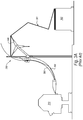
- infeed system 300 includes an infeed wheel 306 configured to engage raw packaging materials 301 and direct them off a fanfold stack 302 and into a converting machine 310.
- infeed wheel 306 has a size specifically designed to prevent additional folding in any layer of raw materials 101.
- converting machine 101 has as a height that is greater than absolutely necessary.
- fanfold stack 302 may be even positioned at a depression.
- the desire to avoid creasing fanfold packaging materials 301 leads to the use of elongated guides 308 that direct packaging materials 301 from infeed wheel 306 into converting machine 310. More particularly, generally S-shaped guides 308 are elongated to have long curve radii so as to prevent creasing in raw materials 101.
- infeed system 400 may use the same converting machine 310, but have a smaller device footprint relative to a converting machine using infeed system 300, or to another converting machine lacking features described herein.
- infeed wheel 406 is configured such that fanfold material 301 may be creased at locations between pre-existing score lines. Therefore, infeed wheel 406 can be much smaller relative to infeed wheel 306 or other infeed wheels that are designed to only bend fanfold material 301 at the pre-existing score lines.
- the smaller infeed wheel 406 can also lead to lower overall converting machine height and length dimensions relative to conventional converting machines, thus allowing the converting machine and infeed system to be located in a building with less vertical clearance and/or a smaller available footprint.
- infeed system 400 may require a vertical clearance of about 2.5m (one hundred inches), whereas infeed system 300 may require a vertical clearance of about 3.8m (one hundred fifty inches) or more.
- infeed guides 406 may be designed with a much smaller infeed guide radius relative to conventional infeed guides. More particularly, the additional creases in same length fanfold material 301 allow fanfold material 301 to have its orientation changed from a substantially vertical position to a substantially horizontal position in a much shorter horizontal distance relative to infeed guides 308 of Figure 3A . This is allowed as the additional creases enable fanfold material 301 to bend around a smaller radius. Furthermore, smaller infeed wheel 406 and/or smaller infeed guides 408 may also enable infeed system 400 to be shipped already assembled due to the overall smaller size of the assembly.
- guides 408 are illustrated as having a generally S-shaped fanfold feed path.
- the S-shaped fanfold fee path of Figure 3B is substantially condensed in both the vertical and horizontal directions relative to the feed path defined by guides 308 in Figure 3A .
- the feed path in Figure 3B may be approximately 2m (eighty inches) high by 127cm (fifty inches) wide, whereas the feed path in Figure 3A may instead be approximately 3m (one hundred twenty inches) high and 1.9m (seventy-five inches) wide.
- aspects of the embodiment in Figure 3B relate to the condensed footprint of infeed system 400. Additional aspects include increased safety of infeed system 400.
- infeed wheel 406 is generally positioned near a top of the S-shaped fanfold feed path that includes infeed guides 408.
- the S-shaped fanfold feed path extends laterally from infeed wheel 406 towards converting machine 310.
- the S-shaped fanfold feed path may extend at least partially towards fanfold stack 302.
- guides 108 extend laterally towards fanfold stack 102 and thus cover a bottom portion of infeed wheel 106. This can further facilitate folding of the raw materials 101 over themselves as they are being directed to the converting mechanism.
- the folding of fanfold in this manner not only further reduces the footprint, but also acts as a barrier to reduce the risk of an inattentive operator being able to touch infeed wheel 106.
- the actual fanfold feed path may vary from one embodiment to the next.
- an S-shaped fanfold feed path is illustrated and described, other various shaped fanfold feed paths may be implemented with various embodiments of the invention.
- a pallet or stack of fanfold material 301 may be placed on the same level as infeed wheel 406, thus producing more of an L or J-shaped fanfold feed path.
- the fanfold feed path may double-back so as to also cover at least a portion of the bottom side of the infeed wheel as an additional safety precaution.
- the relative decrease in size of infeed wheel 406 and/or infeed guides 408 can also allow fanfold material stack 302 to be placed closer to converting mechanism 310 relative to the placement of fanfold material stack 301 and converting mechanism 310 in connection with infeed system 300 of Figure 3A .
- the placement of a fanfold material stack may be substantially directly proximate to the converting mechanism, thereby reducing the device layout footprint when the converting machine is in operation, and also improving loading ease while further substantially reducing the likelihood that an inattentive operator or other person will walk between the fanfold material stack and the converting machine.
- an optional mechanism may be included that allows or causes infeed wheel 406 to rotate in a backward direction.
- Infeed system 400 may further decrease the risk of fanfold packaging materials 301 jamming within infeed system 400 as infeed wheel 406 rotates in a backward direction.
- a spring mechanism may be charged by the forward movement of infeed wheel 406. As a backward feed is needed, the charge can be fully or partially released to thereby back fanfold material 301 out of converting mechanism 310.
- the backward motion may be caused or facilitated by a gravity mechanism that uses gravity to rotate infeed wheel 406 in the backwards direction when fanfold material 301 is backed out of converting mechanism 301.
- the infeed wheel may be coupled to a motor or transmission system that can operate in forward and/or reverse directions.
- the risk of jamming may be reduced due to the additional creases produced by infeed wheel 406.
- the additional creases produced by infeed wheel 406 allow the fanfold material to move more freely within infeed system 400, thus reducing the risk of a jam relative to other converting machines that do not create, and specifically avoid, additional creases.
- infeed guides 408 may also vary and, according to at least one embodiment, can be made of a friction reducing material, or otherwise have a fiction reducing material applied thereto.
- infeed guides 408 may be formed from a metal material that may be coated in a low friction coating.
- a low friction coating allows fanfold material 301 to be fed through infeed guides 408 with less resistance and, in addition, allows fanfold material 301 to be more easily backed out through infeed guides 408 during converting mechanism operations.
- the low friction coating provides protection against risk of a jam during the converting machine operation.
- the infeed guide material may simply be an uncoated metal, alloy, plastic, composite or any other material that is able to be formed into a desired shape.
- the material of guides 408, or a coating or other material applied thereto, if any, may vary from one embodiment to the next.
- guides 408 may be a polished metal material.
- guides 408 may have a powder coat or other type of paint thereon.
- a coating may include one or more of various substances designed to reduce the friction and protect infeed guide 408 (e.g., physical vapor deposition (PVD) coating, Teflon, Starcote, Xylan, carbon-based dry/solid lubricant, near-frictionless carbon (NFC), molybdenum disulphide-based coating, buckminsterfullerene, and the like).
- PVD physical vapor deposition
- Teflon Teflon
- Starcote Starcote
- Xylan carbon-based dry/solid lubricant
- NFC near-frictionless carbon
- molybdenum disulphide-based coating buckminsterfullerene, and the like.
- converting machine 500 may be generally similar to the converting machines described herein. Accordingly, similar components will not be described in detail so as to avoid unnecessary obscuring components of converting machine 500.
- converting machine 100 in Figures 1C it will be noted that converting machine 500 also includes a fanfold stack 502 of packaging materials 502. Unlike the fanfold stack in Figure 1C , however, fanfold stack 502 may have optional additional creases or score lines at intermediate locations within stack 502.
- fanfold stack 502 comprises a plurality of different layers of fanfold material 501.
- Each layer may be defined by opposing score lines 504a, 504b.
- score lines 504a may define the illustrated right side of the layers of packaging materials 501 as they are stacked in stack 502, while score lines 504b may define the illustrated left side of such layers.
- the illustrated embodiment includes creases 512 formed between each of score lines 504a, 504b, although creases 512 may be folds, perforations, score lines, or other features that facilitate bending of raw materials 501 while maintaining stack 502 as a continuous series of connected panels and layers.
- raw materials 501 may be fed into converting mechanism 510 using an infeed wheel 506 and infeed guides 508 in a manner similar to that previously described.
- Infeed wheel 506 may thus have a chord length or other size that allows infeed wheel 506 to engage raw materials 501 at locations other than at only score lines 504a, 504b.
- creases 512 are positioned within the layers of raw packaging materials 501 such that the distance between score lines 504a, 504b and creases 512 generally correspond to the chord length of infeed wheel 506.
- creases 512 may be pre-formed in packaging materials 501 such that infeed wheel 506 may engage creases as well as score lines in raw materials 501, but does not necessarily require that infeed wheel 506 create creases 512 as raw materials are fed around infeed wheel 506.
- pre-formed creases 512 may improve the efficiency of converting machine 500. For example, pre-formed creases 512 may require less force to bend. As a result, infeed wheel 506 may exert reduced forces, which can also decrease the amount of power required in a motor or other drive mechanism. Further, it may allow for lighter-weight, more resilient, or other materials to be used in the manufacture of infeed wheel 506.
- Figure 4 illustrates an exemplary converting machine 500 with an infeed wheel 506 that corresponds to the predetermined length between a crease 512 and a single score line 504a or 504b
- this is merely exemplary.
- multiple creases may be formed in a single layer, such that the length corresponds to a distance between creases 512.
- creases 512 may be formed merely to facilitate movement and flow of raw materials 501, and there may not be any direct integer relationship between the chord length of infeed wheel 506 and creases 512 and/or score lines 504a, 504b.
- Converting machine 600 may generally operate in a manner similar to each of the converting machines and infeed systems described herein. Accordingly, one skilled in the art will appreciate that other aspects of converting machines, converting mechanisms, and infeed systems described herein are equally applicable to converting machine 600.
- converting machine 600 has the ability to draw from multiple different reserves of raw materials 601a-601c to perform converting operations. For instance, in the illustrated embodiment, converting machine 600 may draw from any of three fanfold stacks 602a-602c to perform a converting operation, and without a manual or other adjustment be made to converting machine 600 to adapt it to a different size of raw materials 601.
- Figure 1B illustrates a converting machine 100 that operates with a single size of raw materials 101, and which can be adjusted to accommodate another size of raw materials if necessary
- Converting machine 600 may operate select one of three different sizes that are already configured to flow into converting mechanism 610, without any adjustment.
- a converting machine may be adapted to select from any number of different sizes of raw materials 601a-601c, and need not necessarily have only three sizes that can be accommodated at a single time, as illustrated in Figure 5 .
- a single converting machine may have an infeed system that simultaneously couples converting mechanism 610 to only two different sizes of raw materials, or to four or more sizes of raw materials (e.g., up to twelve stacks or sizes at a single time).
- Converting machine 610 may also be programmed or otherwise configured to select which of the different fanfold stacks 602a-602c is the desired stack for a particular operation.
- a drive mechanism (not shown) may cause a drive shaft 614a-614c corresponding to the desired stack to rotate.
- An infeed wheel 606a-606c may then be rotated by a particular drive shaft 614a-614c, and can feed raw materials 601a-601c in a manner similar to those described herein.
- multiple infeed wheels 606a-606c may engage a single stack of raw materials. This may occur where, for example, raw materials have a large width and two or more infeed wheels can be used to more efficiently lift the materials and feed the materials into converting mechanism 610.
- each of drive shafts 614a-614c and infeed wheels 606a-606c may thus be driven independently of the other drive shafts and infeed wheels, although this doesn't necessarily need to be the case.
- drive shafts 614a-614c may be integrally formed, or otherwise coupled together, to collectively rotate. This may allow, for example, converting machine 600 to concurrently produce multiple packaging templates at a single time.
- Converting machine 600 may, for instance, have different sizes of fanfold stacks 602a-602c so that different configurations of packaging templates may be formed using concurrent converting operations, although in other cases, the same packaging templates may be formed from different sizes of stacks 602a-602c, or stacks 602a-602c may be of the same size and different or the same packaging templates may be concurrently formed therefrom.
- each converting machine and infeed system described herein, or learned upon a review of the disclosure herein may be configured to handle a variety of different fanfold materials.
- the fanfold material is a corrugated board that is typically used in the production of boxes and packaging.
- the converting machine and the converting machine infeed system components may handle various other types of materials such as metals, fabrics, paper, plastics, composites, or the like.
- the way in which the material is arranged before engaging the feed components of the converting machine may also vary.
- the raw materials described herein are generally stacked in vertical stacks. In other embodiments, however, the raw materials may be otherwise aligned or situated. For instance, raw materials may be supplied from a horizontal stack of fanfold materials. In still other embodiments, raw materials may be fed on a roll.
- the infeed systems and converting machines described herein can use score lines, creases, folds, perforations, and the like that have been pre-formed in the raw material and/or create new creases or folds as the material is fed into a converting mechanism.
- a suitable converting mechanism may include multiple cutting, scoring, perforating, creasing, and/or other tools that are each individually controllable within the operative width of the converting mechanism.
- the tools may be supported on guides and controlled by a programmable control unit for individual, lateral positioning on the guides. Tool displacement may then be realized through an endless rotating belt to which tools are individually connected and disconnected.
- Such tools may also be individually controlled to engage the raw packaging materials for cutting and creasing operations. Such operations may be primarily performed in a feed direction through the converting mechanism. Other tools may, however, operate in a direction transverse to the feed direction.
- Such an embodiment is merely exemplary, however, and other converting mechanisms that operate in a wide variety of different manners may be utilized.
Priority Applications (1)
| Application Number | Priority Date | Filing Date | Title |
|---|---|---|---|
| PL10739040T PL2393743T3 (pl) | 2009-02-04 | 2010-02-03 | Układ podajnikowy |
Applications Claiming Priority (2)
| Application Number | Priority Date | Filing Date | Title |
|---|---|---|---|
| US14998509P | 2009-02-04 | 2009-02-04 | |
| PCT/US2010/022983 WO2010091043A1 (en) | 2009-02-04 | 2010-02-03 | Infeed system |
Publications (3)
| Publication Number | Publication Date |
|---|---|
| EP2393743A1 EP2393743A1 (en) | 2011-12-14 |
| EP2393743A4 EP2393743A4 (en) | 2013-03-20 |
| EP2393743B1 true EP2393743B1 (en) | 2019-10-09 |
Family
ID=42542363
Family Applications (1)
| Application Number | Title | Priority Date | Filing Date |
|---|---|---|---|
| EP10739040.3A Active EP2393743B1 (en) | 2009-02-04 | 2010-02-03 | Infeed system |
Country Status (9)
| Country | Link |
|---|---|
| US (1) | US9771231B2 (pt) |
| EP (1) | EP2393743B1 (pt) |
| JP (1) | JP5576884B2 (pt) |
| CN (1) | CN102361809B (pt) |
| BR (1) | BRPI1008107B1 (pt) |
| ES (1) | ES2761917T3 (pt) |
| PL (1) | PL2393743T3 (pt) |
| RU (1) | RU2503608C2 (pt) |
| WO (1) | WO2010091043A1 (pt) |
Families Citing this family (29)
| Publication number | Priority date | Publication date | Assignee | Title |
|---|---|---|---|---|
| JP5576884B2 (ja) | 2009-02-04 | 2014-08-20 | パックサイズ,エルエルシー | 送入システム |
| US9393753B2 (en) | 2010-07-02 | 2016-07-19 | Packsize Llc | Infeed guide system |
| CN103889703B (zh) * | 2011-07-22 | 2016-10-19 | 派克赛泽有限责任公司 | 包装材料的拼接生产 |
| US9818070B2 (en) | 2011-07-22 | 2017-11-14 | Packsize Llc | Tiling production of packaging materials |
| WO2013071080A1 (en) * | 2011-11-10 | 2013-05-16 | Packsize, Llc | Elevated converting machine with outfeed guide |
| EP2802448B1 (en) * | 2012-01-09 | 2016-10-26 | Packsize LLC | Converting machine with an upward outfeed guide |
| ITMI20120901A1 (it) * | 2012-05-24 | 2013-11-25 | Inpeco Ip Ltd | Impianto di automazione di laboratorio con nastro di rivestimento interposto tra un nastro trasportatore automatico e un profilo di scorrimento, e metodo di applicazione di detto nastro di rivestimento. |
| US10922637B2 (en) | 2013-01-18 | 2021-02-16 | Packsize Llc | Tiling production of packaging materials |
| RU2667463C2 (ru) * | 2013-01-18 | 2018-09-19 | ПЭКСАЙЗ ЭлЭлСи | Мозаичное производство упаковочных материалов |
| CN105916672B (zh) * | 2014-01-29 | 2018-02-16 | 未来股份公司 | 用于生产硬纸管的设备和方法 |
| US10071472B2 (en) * | 2014-05-09 | 2018-09-11 | Packsize Llc | Outfeed table |
| US10093438B2 (en) | 2014-12-29 | 2018-10-09 | Packsize Llc | Converting machine |
| SE541881C2 (en) * | 2016-12-19 | 2020-01-02 | Packsize Llc | A box template production system and method |
| US10850469B2 (en) | 2016-06-16 | 2020-12-01 | Packsize Llc | Box forming machine |
| PL3471953T3 (pl) * | 2016-06-16 | 2021-06-14 | Packsize Llc | Układ i sposób wytwarzania szablonów pudełkowych |
| US11242214B2 (en) | 2017-01-18 | 2022-02-08 | Packsize Llc | Converting machine with fold sensing mechanism |
| SE541921C2 (en) | 2017-03-06 | 2020-01-07 | Packsize Llc | A box erecting method and system |
| SE540672C2 (en) | 2017-06-08 | 2018-10-09 | Packsize Llc | Tool head positioning mechanism for a converting machine, and method for positioning a plurality of tool heads in a converting machine |
| US11173685B2 (en) | 2017-12-18 | 2021-11-16 | Packsize Llc | Method for erecting boxes |
| US10752387B2 (en) | 2018-01-31 | 2020-08-25 | Quadient Technologies France | Method and system for creating custom-sized cardboard blanks for packagings and method and system for automatically packaging shipment sets in boxes |
| US11247427B2 (en) * | 2018-04-05 | 2022-02-15 | Avercon BVBA | Packaging machine infeed, separation, and creasing mechanisms |
| US11305903B2 (en) | 2018-04-05 | 2022-04-19 | Avercon BVBA | Box template folding process and mechanisms |
| DE112019003075T5 (de) | 2018-06-21 | 2021-03-25 | Packsize Llc | Verpackungsvorrichtung und systeme |
| SE543046C2 (en) | 2018-09-05 | 2020-09-29 | Packsize Llc | A box erecting method and system |
| US11524474B2 (en) | 2018-11-30 | 2022-12-13 | Packsize Llc | Adjustable cutting and creasing heads for creating angled cuts and creases |
| WO2020146334A1 (en) | 2019-01-07 | 2020-07-16 | Packsize Llc | Box erecting machine |
| US11701854B2 (en) | 2019-03-14 | 2023-07-18 | Packsize Llc | Packaging machine and systems |
| CN114214826A (zh) * | 2021-12-16 | 2022-03-22 | 邵阳东信棉业有限公司 | 一种面料生产用除尘装置 |
| WO2023233287A1 (en) * | 2022-06-01 | 2023-12-07 | C.M.C. S.P.A. | An apparatus for realising at least two continuous cardboard strips of different width for packaging by consecutively joining a respective plurality of cardboard sheets for packaging of different width to one another |
Citations (1)
| Publication number | Priority date | Publication date | Assignee | Title |
|---|---|---|---|---|
| US4264200A (en) * | 1979-09-17 | 1981-04-28 | Xerox Corporation | Platen module for computer fanfold reproduction |
Family Cites Families (24)
| Publication number | Priority date | Publication date | Assignee | Title |
|---|---|---|---|---|
| US2181117A (en) * | 1938-04-09 | 1939-11-28 | Autographic Register Co | Method of making continuous manifolding stationery |
| US3628408A (en) | 1969-10-08 | 1971-12-21 | Xerox Corp | Stamp dispenser |
| CH543020A (de) | 1970-11-23 | 1973-10-15 | Fmc Corp | Getriebe |
| US3743154A (en) * | 1972-01-03 | 1973-07-03 | Minnesota Mining & Mfg | Paper guide |
| US4094451A (en) | 1976-11-04 | 1978-06-13 | Granite State Machine Co., Inc. | Lottery ticket dispenser for break-resistant web material |
| SE443128B (sv) | 1979-12-11 | 1986-02-17 | Tetra Pak Int | Sett och anordning for frammatning av en med biglinjer forsedd materialbana |
| SE450829B (sv) | 1981-02-25 | 1987-08-03 | Tetra Pak Ab | Sett och anordning for frammatning av en materialbana i register med ett pa banan format biglinjemonster |
| SE436023B (sv) * | 1983-03-31 | 1984-11-05 | Tetra Pak Int | Roterbar vinda for ingrepp i register med en biglinjeforsedd materialbana roterbar vinda for ingrepp i register med en biglinjeforsedd materialbana |
| SE461977B (sv) | 1988-09-14 | 1990-04-23 | Profor Ab | Anordning foer intermittent frammatning av en med transversella biglinjer foersedd materialbana |
| US5058872A (en) * | 1989-08-08 | 1991-10-22 | Didde Web Press Corp. | Chain cam |
| DE4117205A1 (de) | 1991-05-27 | 1992-12-03 | Frankenthal Ag Albert | Falzapparat |
| US5836498A (en) * | 1996-04-10 | 1998-11-17 | Interlott Technologies, Inc. | Lottery ticket dispenser |
| US5941451A (en) * | 1996-05-27 | 1999-08-24 | Dexter; William P. | Contact adhesive patterns for sheet stock precluding adhesion of facing sheets in storage |
| IT1290689B1 (it) | 1997-02-20 | 1998-12-10 | Gd Spa | Metodo e dispositivo per il confezionamento di gruppi di prodotti, in particolare pacchetti di sigarette. |
| US6840898B2 (en) | 1998-10-09 | 2005-01-11 | Emsize Ab | Apparatus for the positioning of a tool or a tool holder in a machine designed for processing a sheet material |
| US6189933B1 (en) * | 1999-06-06 | 2001-02-20 | Lyle Ely Felderman | Technique for reducing a large map into a compact paging format |
| US20020125712A1 (en) * | 2001-03-05 | 2002-09-12 | Felderman Lyle Ely | Technique for reducing the vertical dimension of compact paging format |
| US6938397B2 (en) | 2002-09-27 | 2005-09-06 | Met-Tech Corp. | Package wrapping method and apparatus |
| US7100811B2 (en) * | 2003-11-14 | 2006-09-05 | Emsize Ab | Web guide and method |
| US7647752B2 (en) | 2006-07-12 | 2010-01-19 | Greg Magnell | System and method for making custom boxes for objects of random size or shape |
| EP2045942B1 (en) | 2006-07-20 | 2017-04-26 | Sharp Kabushiki Kaisha | Multicarrier signal receiving apparatus and multicarrier signal transmitting apparatus |
| US8707898B2 (en) * | 2008-02-13 | 2014-04-29 | Ncr Corporation | Apparatus for fanfolding media |
| JP5576884B2 (ja) | 2009-02-04 | 2014-08-20 | パックサイズ,エルエルシー | 送入システム |
| US9393753B2 (en) | 2010-07-02 | 2016-07-19 | Packsize Llc | Infeed guide system |
-
2010
- 2010-02-03 JP JP2011549220A patent/JP5576884B2/ja not_active Expired - Fee Related
- 2010-02-03 BR BRPI1008107-0A patent/BRPI1008107B1/pt not_active IP Right Cessation
- 2010-02-03 CN CN201080012998.7A patent/CN102361809B/zh not_active Expired - Fee Related
- 2010-02-03 US US13/147,787 patent/US9771231B2/en active Active
- 2010-02-03 ES ES10739040T patent/ES2761917T3/es active Active
- 2010-02-03 WO PCT/US2010/022983 patent/WO2010091043A1/en active Application Filing
- 2010-02-03 PL PL10739040T patent/PL2393743T3/pl unknown
- 2010-02-03 EP EP10739040.3A patent/EP2393743B1/en active Active
- 2010-02-03 RU RU2011132492/13A patent/RU2503608C2/ru active
Patent Citations (1)
| Publication number | Priority date | Publication date | Assignee | Title |
|---|---|---|---|---|
| US4264200A (en) * | 1979-09-17 | 1981-04-28 | Xerox Corporation | Platen module for computer fanfold reproduction |
Also Published As
| Publication number | Publication date |
|---|---|
| CN102361809A (zh) | 2012-02-22 |
| EP2393743A4 (en) | 2013-03-20 |
| RU2503608C2 (ru) | 2014-01-10 |
| ES2761917T3 (es) | 2020-05-21 |
| PL2393743T3 (pl) | 2020-10-05 |
| RU2011132492A (ru) | 2013-03-10 |
| JP5576884B2 (ja) | 2014-08-20 |
| US20110319242A1 (en) | 2011-12-29 |
| BRPI1008107B1 (pt) | 2020-11-10 |
| JP2012516823A (ja) | 2012-07-26 |
| CN102361809B (zh) | 2015-09-09 |
| US9771231B2 (en) | 2017-09-26 |
| EP2393743A1 (en) | 2011-12-14 |
| WO2010091043A1 (en) | 2010-08-12 |
| BRPI1008107A2 (pt) | 2016-03-08 |
Similar Documents
| Publication | Publication Date | Title |
|---|---|---|
| EP2393743B1 (en) | Infeed system | |
| CN114393610B (zh) | 包装机进给、分离和压痕机构 | |
| EP2588397B1 (en) | Infeed guide system | |
| EP3050684B1 (en) | Elevated converting machine with outfeed guide | |
| CN108430903B (zh) | 真空轮扇折式堆垛机及其使用方法 | |
| JP2012516823A5 (pt) | ||
| EP2308786B1 (en) | Multi-fold interfolding machine structure | |
| CN117320987A (zh) | 用于形成薄片材料并对薄片材料进行扇形折叠的系统和方法 |
Legal Events
| Date | Code | Title | Description |
|---|---|---|---|
| PUAI | Public reference made under article 153(3) epc to a published international application that has entered the european phase |
Free format text: ORIGINAL CODE: 0009012 |
|
| 17P | Request for examination filed |
Effective date: 20110901 |
|
| AK | Designated contracting states |
Kind code of ref document: A1 Designated state(s): AT BE BG CH CY CZ DE DK EE ES FI FR GB GR HR HU IE IS IT LI LT LU LV MC MK MT NL NO PL PT RO SE SI SK SM TR |
|
| DAX | Request for extension of the european patent (deleted) | ||
| A4 | Supplementary search report drawn up and despatched |
Effective date: 20130215 |
|
| RIC1 | Information provided on ipc code assigned before grant |
Ipc: B65H 16/00 20060101ALI20130211BHEP Ipc: B65H 37/06 20060101AFI20130211BHEP Ipc: B31B 1/10 20060101ALI20130211BHEP |
|
| STAA | Information on the status of an ep patent application or granted ep patent |
Free format text: STATUS: EXAMINATION IS IN PROGRESS |
|
| 17Q | First examination report despatched |
Effective date: 20171218 |
|
| RIC1 | Information provided on ipc code assigned before grant |
Ipc: B65H 37/06 20060101AFI20190315BHEP |
|
| GRAP | Despatch of communication of intention to grant a patent |
Free format text: ORIGINAL CODE: EPIDOSNIGR1 |
|
| STAA | Information on the status of an ep patent application or granted ep patent |
Free format text: STATUS: GRANT OF PATENT IS INTENDED |
|
| INTG | Intention to grant announced |
Effective date: 20190429 |
|
| RIN1 | Information on inventor provided before grant (corrected) |
Inventor name: PETTERSSON, NIKLAS |
|
| RAP1 | Party data changed (applicant data changed or rights of an application transferred) |
Owner name: PACKSIZE, LLC |
|
| GRAS | Grant fee paid |
Free format text: ORIGINAL CODE: EPIDOSNIGR3 |
|
| GRAA | (expected) grant |
Free format text: ORIGINAL CODE: 0009210 |
|
| STAA | Information on the status of an ep patent application or granted ep patent |
Free format text: STATUS: THE PATENT HAS BEEN GRANTED |
|
| AK | Designated contracting states |
Kind code of ref document: B1 Designated state(s): AT BE BG CH CY CZ DE DK EE ES FI FR GB GR HR HU IE IS IT LI LT LU LV MC MK MT NL NO PL PT RO SE SI SK SM TR |
|
| REG | Reference to a national code |
Ref country code: GB Ref legal event code: FG4D |
|
| REG | Reference to a national code |
Ref country code: CH Ref legal event code: EP |
|
| REG | Reference to a national code |
Ref country code: IE Ref legal event code: FG4D |
|
| REG | Reference to a national code |
Ref country code: DE Ref legal event code: R096 Ref document number: 602010061433 Country of ref document: DE |
|
| REG | Reference to a national code |
Ref country code: AT Ref legal event code: REF Ref document number: 1188562 Country of ref document: AT Kind code of ref document: T Effective date: 20191115 |
|
| REG | Reference to a national code |
Ref country code: NL Ref legal event code: MP Effective date: 20191009 |
|
| REG | Reference to a national code |
Ref country code: LT Ref legal event code: MG4D |
|
| REG | Reference to a national code |
Ref country code: AT Ref legal event code: MK05 Ref document number: 1188562 Country of ref document: AT Kind code of ref document: T Effective date: 20191009 |
|
| PG25 | Lapsed in a contracting state [announced via postgrant information from national office to epo] |
Ref country code: NO Free format text: LAPSE BECAUSE OF FAILURE TO SUBMIT A TRANSLATION OF THE DESCRIPTION OR TO PAY THE FEE WITHIN THE PRESCRIBED TIME-LIMIT Effective date: 20200109 Ref country code: FI Free format text: LAPSE BECAUSE OF FAILURE TO SUBMIT A TRANSLATION OF THE DESCRIPTION OR TO PAY THE FEE WITHIN THE PRESCRIBED TIME-LIMIT Effective date: 20191009 Ref country code: BG Free format text: LAPSE BECAUSE OF FAILURE TO SUBMIT A TRANSLATION OF THE DESCRIPTION OR TO PAY THE FEE WITHIN THE PRESCRIBED TIME-LIMIT Effective date: 20200109 Ref country code: LT Free format text: LAPSE BECAUSE OF FAILURE TO SUBMIT A TRANSLATION OF THE DESCRIPTION OR TO PAY THE FEE WITHIN THE PRESCRIBED TIME-LIMIT Effective date: 20191009 Ref country code: AT Free format text: LAPSE BECAUSE OF FAILURE TO SUBMIT A TRANSLATION OF THE DESCRIPTION OR TO PAY THE FEE WITHIN THE PRESCRIBED TIME-LIMIT Effective date: 20191009 Ref country code: NL Free format text: LAPSE BECAUSE OF FAILURE TO SUBMIT A TRANSLATION OF THE DESCRIPTION OR TO PAY THE FEE WITHIN THE PRESCRIBED TIME-LIMIT Effective date: 20191009 Ref country code: GR Free format text: LAPSE BECAUSE OF FAILURE TO SUBMIT A TRANSLATION OF THE DESCRIPTION OR TO PAY THE FEE WITHIN THE PRESCRIBED TIME-LIMIT Effective date: 20200110 Ref country code: PT Free format text: LAPSE BECAUSE OF FAILURE TO SUBMIT A TRANSLATION OF THE DESCRIPTION OR TO PAY THE FEE WITHIN THE PRESCRIBED TIME-LIMIT Effective date: 20200210 Ref country code: SE Free format text: LAPSE BECAUSE OF FAILURE TO SUBMIT A TRANSLATION OF THE DESCRIPTION OR TO PAY THE FEE WITHIN THE PRESCRIBED TIME-LIMIT Effective date: 20191009 Ref country code: LV Free format text: LAPSE BECAUSE OF FAILURE TO SUBMIT A TRANSLATION OF THE DESCRIPTION OR TO PAY THE FEE WITHIN THE PRESCRIBED TIME-LIMIT Effective date: 20191009 |
|
| PGFP | Annual fee paid to national office [announced via postgrant information from national office to epo] |
Ref country code: GB Payment date: 20200227 Year of fee payment: 11 Ref country code: ES Payment date: 20200302 Year of fee payment: 11 |
|
| REG | Reference to a national code |
Ref country code: ES Ref legal event code: FG2A Ref document number: 2761917 Country of ref document: ES Kind code of ref document: T3 Effective date: 20200521 |
|
| PG25 | Lapsed in a contracting state [announced via postgrant information from national office to epo] |
Ref country code: HR Free format text: LAPSE BECAUSE OF FAILURE TO SUBMIT A TRANSLATION OF THE DESCRIPTION OR TO PAY THE FEE WITHIN THE PRESCRIBED TIME-LIMIT Effective date: 20191009 Ref country code: IS Free format text: LAPSE BECAUSE OF FAILURE TO SUBMIT A TRANSLATION OF THE DESCRIPTION OR TO PAY THE FEE WITHIN THE PRESCRIBED TIME-LIMIT Effective date: 20200224 |
|
| PGFP | Annual fee paid to national office [announced via postgrant information from national office to epo] |
Ref country code: FR Payment date: 20200225 Year of fee payment: 11 |
|
| REG | Reference to a national code |
Ref country code: DE Ref legal event code: R097 Ref document number: 602010061433 Country of ref document: DE |
|
| PG2D | Information on lapse in contracting state deleted |
Ref country code: IS |
|
| PG25 | Lapsed in a contracting state [announced via postgrant information from national office to epo] |
Ref country code: CZ Free format text: LAPSE BECAUSE OF FAILURE TO SUBMIT A TRANSLATION OF THE DESCRIPTION OR TO PAY THE FEE WITHIN THE PRESCRIBED TIME-LIMIT Effective date: 20191009 Ref country code: RO Free format text: LAPSE BECAUSE OF FAILURE TO SUBMIT A TRANSLATION OF THE DESCRIPTION OR TO PAY THE FEE WITHIN THE PRESCRIBED TIME-LIMIT Effective date: 20191009 Ref country code: DK Free format text: LAPSE BECAUSE OF FAILURE TO SUBMIT A TRANSLATION OF THE DESCRIPTION OR TO PAY THE FEE WITHIN THE PRESCRIBED TIME-LIMIT Effective date: 20191009 Ref country code: EE Free format text: LAPSE BECAUSE OF FAILURE TO SUBMIT A TRANSLATION OF THE DESCRIPTION OR TO PAY THE FEE WITHIN THE PRESCRIBED TIME-LIMIT Effective date: 20191009 Ref country code: IS Free format text: LAPSE BECAUSE OF FAILURE TO SUBMIT A TRANSLATION OF THE DESCRIPTION OR TO PAY THE FEE WITHIN THE PRESCRIBED TIME-LIMIT Effective date: 20200209 |
|
| PLBE | No opposition filed within time limit |
Free format text: ORIGINAL CODE: 0009261 |
|
| STAA | Information on the status of an ep patent application or granted ep patent |
Free format text: STATUS: NO OPPOSITION FILED WITHIN TIME LIMIT |
|
| PG25 | Lapsed in a contracting state [announced via postgrant information from national office to epo] |
Ref country code: SK Free format text: LAPSE BECAUSE OF FAILURE TO SUBMIT A TRANSLATION OF THE DESCRIPTION OR TO PAY THE FEE WITHIN THE PRESCRIBED TIME-LIMIT Effective date: 20191009 Ref country code: SM Free format text: LAPSE BECAUSE OF FAILURE TO SUBMIT A TRANSLATION OF THE DESCRIPTION OR TO PAY THE FEE WITHIN THE PRESCRIBED TIME-LIMIT Effective date: 20191009 |
|
| 26N | No opposition filed |
Effective date: 20200710 |
|
| REG | Reference to a national code |
Ref country code: CH Ref legal event code: PL |
|
| REG | Reference to a national code |
Ref country code: BE Ref legal event code: MM Effective date: 20200229 |
|
| PG25 | Lapsed in a contracting state [announced via postgrant information from national office to epo] |
Ref country code: MC Free format text: LAPSE BECAUSE OF FAILURE TO SUBMIT A TRANSLATION OF THE DESCRIPTION OR TO PAY THE FEE WITHIN THE PRESCRIBED TIME-LIMIT Effective date: 20191009 Ref country code: LU Free format text: LAPSE BECAUSE OF NON-PAYMENT OF DUE FEES Effective date: 20200203 |
|
| PG25 | Lapsed in a contracting state [announced via postgrant information from national office to epo] |
Ref country code: SI Free format text: LAPSE BECAUSE OF FAILURE TO SUBMIT A TRANSLATION OF THE DESCRIPTION OR TO PAY THE FEE WITHIN THE PRESCRIBED TIME-LIMIT Effective date: 20191009 Ref country code: CH Free format text: LAPSE BECAUSE OF NON-PAYMENT OF DUE FEES Effective date: 20200229 Ref country code: LI Free format text: LAPSE BECAUSE OF NON-PAYMENT OF DUE FEES Effective date: 20200229 |
|
| PGFP | Annual fee paid to national office [announced via postgrant information from national office to epo] |
Ref country code: PL Payment date: 20200121 Year of fee payment: 11 |
|
| PG25 | Lapsed in a contracting state [announced via postgrant information from national office to epo] |
Ref country code: IE Free format text: LAPSE BECAUSE OF NON-PAYMENT OF DUE FEES Effective date: 20200203 |
|
| PG25 | Lapsed in a contracting state [announced via postgrant information from national office to epo] |
Ref country code: BE Free format text: LAPSE BECAUSE OF NON-PAYMENT OF DUE FEES Effective date: 20200229 |
|
| GBPC | Gb: european patent ceased through non-payment of renewal fee |
Effective date: 20210203 |
|
| PG25 | Lapsed in a contracting state [announced via postgrant information from national office to epo] |
Ref country code: GB Free format text: LAPSE BECAUSE OF NON-PAYMENT OF DUE FEES Effective date: 20210203 Ref country code: FR Free format text: LAPSE BECAUSE OF NON-PAYMENT OF DUE FEES Effective date: 20210228 |
|
| REG | Reference to a national code |
Ref country code: ES Ref legal event code: FD2A Effective date: 20220504 |
|
| PG25 | Lapsed in a contracting state [announced via postgrant information from national office to epo] |
Ref country code: TR Free format text: LAPSE BECAUSE OF FAILURE TO SUBMIT A TRANSLATION OF THE DESCRIPTION OR TO PAY THE FEE WITHIN THE PRESCRIBED TIME-LIMIT Effective date: 20191009 Ref country code: MT Free format text: LAPSE BECAUSE OF FAILURE TO SUBMIT A TRANSLATION OF THE DESCRIPTION OR TO PAY THE FEE WITHIN THE PRESCRIBED TIME-LIMIT Effective date: 20191009 Ref country code: CY Free format text: LAPSE BECAUSE OF FAILURE TO SUBMIT A TRANSLATION OF THE DESCRIPTION OR TO PAY THE FEE WITHIN THE PRESCRIBED TIME-LIMIT Effective date: 20191009 |
|
| PGFP | Annual fee paid to national office [announced via postgrant information from national office to epo] |
Ref country code: IT Payment date: 20220222 Year of fee payment: 13 |
|
| PG25 | Lapsed in a contracting state [announced via postgrant information from national office to epo] |
Ref country code: MK Free format text: LAPSE BECAUSE OF FAILURE TO SUBMIT A TRANSLATION OF THE DESCRIPTION OR TO PAY THE FEE WITHIN THE PRESCRIBED TIME-LIMIT Effective date: 20191009 |
|
| PG25 | Lapsed in a contracting state [announced via postgrant information from national office to epo] |
Ref country code: ES Free format text: LAPSE BECAUSE OF NON-PAYMENT OF DUE FEES Effective date: 20210204 |
|
| PG25 | Lapsed in a contracting state [announced via postgrant information from national office to epo] |
Ref country code: PL Free format text: LAPSE BECAUSE OF NON-PAYMENT OF DUE FEES Effective date: 20210203 |
|
| PGFP | Annual fee paid to national office [announced via postgrant information from national office to epo] |
Ref country code: DE Payment date: 20230223 Year of fee payment: 14 |
|
| P01 | Opt-out of the competence of the unified patent court (upc) registered |
Effective date: 20230530 |
|
| PG25 | Lapsed in a contracting state [announced via postgrant information from national office to epo] |
Ref country code: IT Free format text: LAPSE BECAUSE OF NON-PAYMENT OF DUE FEES Effective date: 20230203 |