EP2393712B1 - Suspension assembly for an aircraft turbojet engine - Google Patents
Suspension assembly for an aircraft turbojet engine Download PDFInfo
- Publication number
- EP2393712B1 EP2393712B1 EP10707330.6A EP10707330A EP2393712B1 EP 2393712 B1 EP2393712 B1 EP 2393712B1 EP 10707330 A EP10707330 A EP 10707330A EP 2393712 B1 EP2393712 B1 EP 2393712B1
- Authority
- EP
- European Patent Office
- Prior art keywords
- suspension assembly
- turbojet engine
- assembly according
- connecting rods
- thrust
- Prior art date
- Legal status (The legal status is an assumption and is not a legal conclusion. Google has not performed a legal analysis and makes no representation as to the accuracy of the status listed.)
- Not-in-force
Links
- 239000000725 suspension Substances 0.000 title claims description 20
- 238000009413 insulation Methods 0.000 claims description 16
- 238000005192 partition Methods 0.000 claims description 13
- 238000002955 isolation Methods 0.000 claims description 10
- 238000001816 cooling Methods 0.000 claims description 2
- 230000000740 bleeding effect Effects 0.000 claims 1
- 238000011084 recovery Methods 0.000 description 14
- 238000012423 maintenance Methods 0.000 description 7
- 239000000463 material Substances 0.000 description 5
- 238000011144 upstream manufacturing Methods 0.000 description 5
- RTAQQCXQSZGOHL-UHFFFAOYSA-N Titanium Chemical compound [Ti] RTAQQCXQSZGOHL-UHFFFAOYSA-N 0.000 description 4
- 239000002131 composite material Substances 0.000 description 4
- 229910052719 titanium Inorganic materials 0.000 description 4
- 239000010936 titanium Substances 0.000 description 4
- VYPSYNLAJGMNEJ-UHFFFAOYSA-N Silicium dioxide Chemical compound O=[Si]=O VYPSYNLAJGMNEJ-UHFFFAOYSA-N 0.000 description 2
- 229910000831 Steel Inorganic materials 0.000 description 2
- XAGFODPZIPBFFR-UHFFFAOYSA-N aluminium Chemical compound [Al] XAGFODPZIPBFFR-UHFFFAOYSA-N 0.000 description 2
- 229910052782 aluminium Inorganic materials 0.000 description 2
- 229940082150 encore Drugs 0.000 description 2
- 239000010959 steel Substances 0.000 description 2
- 229910000851 Alloy steel Inorganic materials 0.000 description 1
- 101100536354 Drosophila melanogaster tant gene Proteins 0.000 description 1
- 230000004888 barrier function Effects 0.000 description 1
- 238000002485 combustion reaction Methods 0.000 description 1
- 239000000835 fiber Substances 0.000 description 1
- 238000007689 inspection Methods 0.000 description 1
- 239000011810 insulating material Substances 0.000 description 1
- 230000005855 radiation Effects 0.000 description 1
- 238000005070 sampling Methods 0.000 description 1
- 239000000377 silicon dioxide Substances 0.000 description 1
- 239000010935 stainless steel Substances 0.000 description 1
- 229910001220 stainless steel Inorganic materials 0.000 description 1
- 230000000007 visual effect Effects 0.000 description 1
- 238000011179 visual inspection Methods 0.000 description 1
Images

Classifications
-
- B—PERFORMING OPERATIONS; TRANSPORTING
- B64—AIRCRAFT; AVIATION; COSMONAUTICS
- B64D—EQUIPMENT FOR FITTING IN OR TO AIRCRAFT; FLIGHT SUITS; PARACHUTES; ARRANGEMENT OR MOUNTING OF POWER PLANTS OR PROPULSION TRANSMISSIONS IN AIRCRAFT
- B64D27/00—Arrangement or mounting of power plants in aircraft; Aircraft characterised by the type or position of power plants
- B64D27/40—Arrangements for mounting power plants in aircraft
- B64D27/406—Suspension arrangements specially adapted for supporting thrust loads, e.g. thrust links
-
- B—PERFORMING OPERATIONS; TRANSPORTING
- B64—AIRCRAFT; AVIATION; COSMONAUTICS
- B64D—EQUIPMENT FOR FITTING IN OR TO AIRCRAFT; FLIGHT SUITS; PARACHUTES; ARRANGEMENT OR MOUNTING OF POWER PLANTS OR PROPULSION TRANSMISSIONS IN AIRCRAFT
- B64D29/00—Power-plant nacelles, fairings, or cowlings
- B64D29/06—Attaching of nacelles, fairings or cowlings
-
- Y—GENERAL TAGGING OF NEW TECHNOLOGICAL DEVELOPMENTS; GENERAL TAGGING OF CROSS-SECTIONAL TECHNOLOGIES SPANNING OVER SEVERAL SECTIONS OF THE IPC; TECHNICAL SUBJECTS COVERED BY FORMER USPC CROSS-REFERENCE ART COLLECTIONS [XRACs] AND DIGESTS
- Y02—TECHNOLOGIES OR APPLICATIONS FOR MITIGATION OR ADAPTATION AGAINST CLIMATE CHANGE
- Y02T—CLIMATE CHANGE MITIGATION TECHNOLOGIES RELATED TO TRANSPORTATION
- Y02T50/00—Aeronautics or air transport
- Y02T50/40—Weight reduction
Definitions
- the present invention relates to a suspension assembly for an aircraft turbojet, and to a propulsion assembly comprising such a suspension assembly, a turbojet and a nacelle.
- a propulsion assembly comprising such a suspension assembly, a turbojet and a nacelle.
- an aircraft turbojet engine is housed inside a nacelle and connected to a mast allowing the suspension of the propulsion unit thus formed under an aircraft wing or adjacent to the fuselage.
- Thrust recovery rods are interposed between the mast and the turbojet engine gas generator, so as to take up the forces generated by the thrust of the engine.
- the present invention is intended to provide means for the use of lighter materials for the thrust recovery rods.
- a suspension assembly for an aircraft turbojet comprising a mast and rods for taking up the thrust of said turbojet engine connected to said mast, remarkable in that it comprises means, distinct from said mast, to thermally insulate said rods relative to said turbojet engine.
- these rods can therefore be made of materials that are less heat-resistant and lighter, such as as titanium, aluminum or composite materials.
- the present invention also relates to a propulsion assembly, comprising a suspension assembly according to the above, a turbojet engine suspended from said suspension assembly, and a nacelle enveloping said suspension assembly and said turbojet engine.
- said propulsion assembly may comprise air sampling channels in the secondary flow zone of said nacelle, for cooling said thermal insulation means: these channels contribute to maintaining the connecting rods at low temperature.
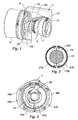
- the assembly according to the invention comprises a mast 1 intended to be fixed under an aircraft wing, adapted to support a turbojet engine 3 comprising an upstream part forming a fan 5 and a downstream part forming a gas generator 7.
- the mast 1 is connected respectively to these upstream and downstream parts of the turbojet engine 3 by upstream 9 and downstream 11 ironwork.
- Thrust recovery rods 13a and 13b conventionally extend between the upstream portion 15 of the gas generator 7 and the rear portion 17 of the mast 1.
- a thermal insulation sheath 19 which can be formed for example of a sheet of titanium or steel, or a cover made of a stainless steel film encapsulating an insulating material such as silica fiber simultaneously envelops both 13a and 13b thrust recovery rods, thus forming on the one hand a thermal insulation of these two rods vis-à-vis the heat emitted by the gas generator 7, and on the other hand a heat shield for the mast 1.
- This sheath 19 which envelops the two thrust recovery rods is preferably formed of two half-sheaths removably attached to one another, which allows quick access to the connecting rods 13a, 13b for visual inspection and / or for maintenance operations.
- the assembly according to the invention further comprises a nacelle adapted to envelop the turbojet engine 3, not represented on the figure 1 but represented on the Figures 3 to 8 which will be commented further.
- each sheath 19 may be formed of two half-sheaths 21a, 21b, connected to the connecting rod 13 via sheath supports 23a, 23b.
- the sheath 19 may extend over all or part of the length of the thrust rods 13a, 13b.
- upstream 9 and downstream 11 fittings can also be covered by thermal insulation sheaths.
- a partition 25 is interposed between the gas generator 7 and the thrust recovery rods 13a, 13b.
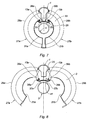
- This nacelle comprises two half-shells 27a, 27b, each pivotally mounted around the mast 1 between a normal operating position visible on the figures 3 , 4 and 7 , and a maintenance position, shown on the Figures 5, 6 and 8 .
- Each half-shell 27a, 27b comprises an external structure 29a, 29b, and an internal structure 31a, 31b, these external and internal structures defining an annular channel 33 in which the fresh air sent by the fan 5 circulates.
- the partition 25, which extends substantially over the entire length of the gas generator 7, has on its lateral edges seals 35a, 35b cooperating with the internal structures 31a, 31b in the normal operating position (see figure 7 ).
- the partition 25 can be held on the gas generator 7 via a support 37a, 37b, but this partition can also be maintained, alternatively or additionally, by supports (not shown) attached to the thrust recovery rods 13a, 13b.
- This partition 25 could still be supported by support means connected to the mast 1.
- Air intakes 39a, 39b are preferably provided in the flow of fresh air circulating in the annular channel 33, so as to contribute to keeping the thrust rods 13a, 13b at a low temperature.
- the partition 25 may be formed of a material resistant to high temperatures (sheet of titanium or steel for example) or be coated with a thermal cover 41 resistant to high temperatures, as shown on the figures 6 and 8 .
- the thermal insulation of the thrust transfer rods 13a, 13b makes it possible to maintain these at relatively low temperatures, especially if they are cooled by means of air from the cold flow generated by the blower.
- the partition 25 furthermore makes it possible to insulate the mast 1 with respect to the heat radiated by the gas generator 7, which makes it possible to envisage making this mast also of lighter materials.
- the present invention can be applied both to a girder or gate thrust reverser nacelle and to a so-called smooth gondola (without thrust reverser).
Landscapes
- Engineering & Computer Science (AREA)
- Aviation & Aerospace Engineering (AREA)
- Structures Of Non-Positive Displacement Pumps (AREA)
- Wind Motors (AREA)
Description
La présente invention se rapporte à un ensemble de suspension pour turboréacteur d'aéronef, et à un ensemble propulsif comprenant un tel ensemble de suspension, un turboréacteur et une nacelle. Un exemple de l'art antérieur est fourni par le document
Comme cela est connu de la technique antérieure, un turboréacteur d'aéronef est logé à l'intérieur d'une nacelle et relié à un mât permettant la suspension de l'ensemble propulsif ainsi constitué sous une aile d'aéronef ou adjacent au fuselage.As is known from the prior art, an aircraft turbojet engine is housed inside a nacelle and connected to a mast allowing the suspension of the propulsion unit thus formed under an aircraft wing or adjacent to the fuselage.
Des bielles de reprise de poussée sont interposées entre le mât et le générateur de gaz du turboréacteur, de manière à reprendre les efforts engendrés par la poussée du moteur.Thrust recovery rods are interposed between the mast and the turbojet engine gas generator, so as to take up the forces generated by the thrust of the engine.
Dans les ensembles propulsifs de la technique antérieure, ces bielles sont soumises à des températures très élevées engendrées notamment par la chambre de combustion du moteur, ce qui nécessite l'utilisation d'alliages d'acier particuliers, dont le poids est important.In propulsion systems of the prior art, these rods are subjected to very high temperatures generated in particular by the combustion chamber of the engine, which requires the use of particular steel alloys, whose weight is important.
La présente invention a notamment pour but de fournir des moyens permettant l'utilisation de matériaux moins lourds pour les bielles de reprise de poussée.The present invention is intended to provide means for the use of lighter materials for the thrust recovery rods.
On atteint ce but de l'invention avec un ensemble de suspension pour turboréacteur d'aéronef, comprenant un mât et des bielles de reprise de la poussée dudit turboréacteur reliées audit mât, remarquable en ce qu'il comprend des moyens, distincts dudit mât, pour isoler thermiquement lesdites bielles par rapport audit turboréacteur.This object of the invention is achieved with a suspension assembly for an aircraft turbojet, comprising a mast and rods for taking up the thrust of said turbojet engine connected to said mast, remarkable in that it comprises means, distinct from said mast, to thermally insulate said rods relative to said turbojet engine.
La présence des moyens d'isolation thermique des bielles permet d'isoler celles-ci du rayonnement et de la convection de la chaleur émise par le moteur : ces bielles peuvent donc être réalisées dans des matériaux moins résistants à la chaleur et plus légers, tels que le titane, l'aluminium ou des matériaux composites.The presence of the thermal insulation means of the connecting rods enables them to be isolated from the radiation and the convection of the heat emitted by the engine: these rods can therefore be made of materials that are less heat-resistant and lighter, such as as titanium, aluminum or composite materials.
Suivant d'autres caractéristiques optionnelles de l'ensemble de suspension selon l'invention :
- lesdits moyens d'isolation comprennent des gaines d'isolation indépendantes pour chaque bielle de reprise de poussée : ces gaines permettent de réaliser de manière très simple l'isolation des bielles ;
- lesdits moyens d'isolation comprennent une gaine d'isolation commune auxdites bielles : cette solution permet de réduire le nombre de pièces ;
- ladite ou lesdites gaine(s) sont amovibles : ceci permet de faciliter l'inspection des bielles ;
- lesdits moyens d'isolation thermique comprennent une cloison d'isolation positionnée entre lesdites bielles de reprise de poussée et la zone destinée à être occupée par ledit turboréacteur : cette solution permet en outre de protéger le mât vis-à-vis de la chaleur, et ainsi de réaliser au moins une partie du mât en matériaux composites, et donc de réduire encore le poids de l'ensemble ;
- ladite cloison est fixée sur ledit mât et/ou sur lesdites bielles et/ou est apte à être fixée sur ledit turboréacteur ;
- ladite cloison est apte à agir en tant que barrière feu en cas d'incendie dans le compartiment moteur, de façon à empêcher sa propagation aux bielles de reprise de poussée et au mât ;
- des joints d'étanchéité sont interposés entre ladite cloison d'isolation et la structure interne de la dite nacelle : la présence de ces joints permet d'empêcher le transfert de chaleur du moteur par convection thermique, ainsi que la propagation d'une flamme ou de gaz chauds en cas de feu dans le compartiment moteur..
- said insulating means comprise independent insulating sheaths for each thrust recovery connecting rod: these sheaths make it possible in a very simple manner to insulate the connecting rods;
- said insulation means comprise an insulation sheath common to said connecting rods: this solution makes it possible to reduce the number of parts;
- said sheath (s) are removable: this makes it easier to inspect the connecting rods;
- said thermal insulation means comprise an insulation wall positioned between said thrust recovery rods and the zone intended to be occupied by said turbojet engine: this solution also makes it possible to protect the mast from heat, and thus to achieve at least a portion of the mast composite materials, and thus to further reduce the weight of the assembly;
- said partition is fixed on said mast and / or on said rods and / or is adapted to be fixed on said turbojet engine;
- said partition is able to act as a fire barrier in the event of a fire in the engine compartment, so as to prevent its propagation to the thrust recovery rods and to the mast;
- seals are interposed between said insulation wall and the internal structure of said nacelle: the presence of these seals prevents the heat transfer of the engine by thermal convection, and the propagation of a flame or hot gas in case of fire in the engine compartment.
La présente invention se rapporte également à un ensemble propulsif, comprenant un ensemble de suspension conforme à ce qui précède, un turboréacteur suspendu audit ensemble de suspension, et une nacelle enveloppant ledit ensemble de suspension et ledit turboréacteur.The present invention also relates to a propulsion assembly, comprising a suspension assembly according to the above, a turbojet engine suspended from said suspension assembly, and a nacelle enveloping said suspension assembly and said turbojet engine.
De manière optionnelle, ledit ensemble propulsif peut comprendre des canaux de prélèvement d'air dans la zone de flux secondaire de ladite nacelle, pour refroidir lesdits moyens d'isolation thermique : ces canaux contribuent au maintien des bielles à basse température.Optionally, said propulsion assembly may comprise air sampling channels in the secondary flow zone of said nacelle, for cooling said thermal insulation means: these channels contribute to maintaining the connecting rods at low temperature.
D'autres caractéristiques et avantages de la présente invention apparaîtront à la lumière de la description qui va suivre, et à l'examen des figures ci-annexées, dans lesquelles :
- la
figure 1 représente une vue en perspective d'un premier mode de réalisation d'un ensemble selon l'invention, - la
figure 2 représente (à plus grande échelle) une vue en coupe transversale d'une bielle de reprise de poussée d'un ensemble selon l'invention réalisé conformément à un autre mode de réalisation,
- les
figures 3 et4 sont des vues de devant et de derrière, légèrement.en perspective, d'un ensemble selon l'invention réalisé conformément à encore un autre mode de réalisation, - les
figures 5 et 6 sont des vues correspondant respectivement auxfigures 3 et4 , lorsque l'ensemble selon l'invention est représenté en position de maintenance, et - les
figures 7 et 8 sont des vues en coupe schématique de l'ensemble desfigures 3 à 6 , représenté respectivement en position de fonctionnement normal et en position de maintenance.
- the
figure 1 represents a perspective view of a first embodiment of an assembly according to the invention, - the
figure 2 represents (on a larger scale) a cross-sectional view of a rod of thrust recovery of a set according to the invention realized according to another embodiment,
- the
figures 3 and4 are front and rear views, slightly in perspective, of an assembly according to the invention made according to yet another embodiment, - the
Figures 5 and 6 are views corresponding respectively tofigures 3 and4 when the assembly according to the invention is represented in the maintenance position, and - the
Figures 7 and 8 are schematic sectional views of allFigures 3 to 6 , respectively represented in the normal operating position and in the maintenance position.
En se reportant à la
Le mât 1 est relié respectivement à ces parties amont et aval du turboréacteur 3 par des ferrures amont 9 et aval 11.The
Des bielles de reprise de poussée 13a et 13b s'étendent classiquement entre la partie amont 15 du générateur de gaz 7 et la partie arrière 17 du mât 1.
Ces deux bielles 13a, 13b sont écartées l'une de l'autre dans la zone 15, et convergent en direction de la zone arrière 17 du mât 1.These two connecting
Une gaine d'isolation thermique 19, pouvant être formée par exemple d'une tôle en titane ou acier, ou d'une couverture composée d'un film d'acier inoxydable encapsulant un matériau isolant comme de la fibre de silice enveloppe simultanément les deux bielles de reprise de poussée 13a et 13b, formant ainsi d'une part une isolation thermique de ces deux bielles vis-à-vis de la chaleur émise par le générateur de gaz 7, et d'autre part un écran de protection contre la chaleur pour le mât 1.A
Cette gaine 19 qui enveloppe les deux bielles de reprise de poussée est de préférence formée de deux demi-gaines fixées de manière amovible l'une sur l'autre, ce qui permet d'accéder rapidement aux bielles 13a, 13b pour un examen visuel et/ou pour des opérations de maintenance.This
L'ensemble selon l'invention comprend en outre une nacelle apte à envelopper le turboréacteur 3, non représentée sur la
En solution alternative à une unique gaine 19 qui enveloppe les deux bielles de reprise de poussée 13a, 13b, on peut envisager une gaine 19 pour chaque bielle 13, comme cela est visible sur la
Comme cela est visible sur cette figure, chaque gaine 19 peut être formée de deux demi gaines 21 a, 21 b, reliées à la bielle 13 par l'intermédiaire de supports de gaine 23a, 23b.As can be seen in this figure, each
A noter que dans le mode de réalisation de la
A noter également que les ferrures amont 9 et aval 11 peuvent aussi être recouvertes par des gaines d'isolation thermique.It should also be noted that the upstream 9 and downstream 11 fittings can also be covered by thermal insulation sheaths.
Dans le mode de réalisation des
On peut voir sur ces
Cette nacelle comporte deux demi coques 27a, 27b, montées chacune pivotante autour du mât 1 entre une position de fonctionnement normal visible sur les
Chaque demi-coque 27a, 27b comporte une structure externe 29a, 29b, et une structure interne 31 a, 31 b, ces structures externe et interne définissant un canal annulaire 33 dans lequel circule l'air frais envoyé par la soufflante 5.Each half-
La cloison 25, qui s'étend sensiblement sur toute la longueur du générateur de gaz 7, comporte sur ses bords latéraux des joints 35a, 35b coopérant avec les structures internes 31 a, 31 b en position de fonctionnement normal (voir
Ces joints permettent de réaliser une étanchéité entre la cloison 25 et les structures internes 31 a, 31 b, ce qui permet de parfaire l'isolation thermique des bielles de reprise de poussée 13a, 13b et du mât 1 par rapport au générateur de gaz 7.These seals make it possible to provide a seal between the
Comme cela est visible notamment sur les
Cette cloison 25 pourrait encore être soutenue par des moyens de support reliés au mât 1.This
On prévoit de préférence des prises d'air 39a, 39b dans le flux d'air frais circulant dans le canal annulaire 33, de manière à contribuer au maintien à basse de température des bielles de reprise de poussée 13a, 13b.
A noter que la cloison 25 peut être formée dans un matériau résistant aux températures élevées (tôle de titane ou d'acier par exemple) ou bien être revêtue d'une couverture thermique 41 résistant aux températures élevées, comme cela est représenté sur les
Les avantages de la présente invention résultent directement de la description qui précède : l'isolation thermique des bielles de reprise de poussée 13a, 13b permet de maintenir celles-ci à des températures relativement basses, et ce a fortiori si elles sont refroidies par de l'air en provenance du flux froid engendré par la soufflante.The advantages of the present invention result directly from the foregoing description: the thermal insulation of the
Ce maintien à basses températures permet de réaliser les bielles de reprise de poussée dans des matériaux moins résistants aux hautes températures, mais plus légers, tels que le titane, l'aluminium ou des matériaux composite.This maintenance at low temperatures makes it possible to achieve the thrust rods in materials that are less resistant to high temperatures, but lighter, such as titanium, aluminum or composite materials.
Dans le cas particulier du mode de réalisation des
On notera que dans l'ensemble des modes de réalisation ci-dessus exposés, l'accès visuel et physique aux bielles de reprise de poussée est très facile : dans les modes de réalisation des
Bien entendu, la présente invention n'est nullement limitée aux modes de réalisations décrits et représentés, fournis à titre de simples exemples.Of course, the present invention is not limited to the embodiments described and shown, provided as simple examples.
On notera que la présente invention peut s'appliquer tant à une nacelle à inverseur de poussée à grilles ou à porte qu'à une nacelle dite lisse (sans inverseur de poussée).It should be noted that the present invention can be applied both to a girder or gate thrust reverser nacelle and to a so-called smooth gondola (without thrust reverser).
Claims (9)
- A suspension assembly for an aircraft turbojet engine (3), comprising a pylon (1) and connecting rods (13a, 13b) for taking up the thrust of said turbojet engine (3) connected to said pylon (1), characterized in that it comprises means (19, 25), distinct from said pylon (1), for thermally insulating said connecting rods (13a, 13b) with respect to said turbojet engine (3).
- Ensemble de suspension selon la revendication 1 , caractérisé en ce que lesdits moyens d'isolation comprennent des gaines d'isolation indépendantes pour chaque bielle de reprise de poussée (13a, 13b). The suspension assembly according to claim 1, characterized in that said insulating means comprise Independent insulating sheaths for each connecting rod (13a, 13b) taking up the thrust.
- The suspension assembly according to claim 1, characterized In that said insulating means comprise an insulation sheath (19) common to said connecting rods (13a, 13b).
- The suspension assembly according to one of claims 2 or 3, characterized in that said sheath(s) (19) is(are) removable.
- The suspension assembly according to claim 1, characterized in that said thermal insulation means comprise an insulation partition (25) positioned between said connecting rods (13a, 13b) for taking up the thrust and the area intended to be occupied by said turbojet engine (3).
- The suspension assembly according to claim 5, characterized in that said partition (25) is attached on said pylon (1) and/or on said connecting rods (13a, 13b) and/or is able to be attached on said turbojet engine (3).
- The suspension assembly according to one of claims 5 or 6, characterized in that seal gaskets (35a, 35b) are positioned on the edges of said partition (25) which are intended to co-operate with a nacelle internal structure (31 a, 31b).
- A propulsion assembly, comprising a suspension assembly according to any of the preceding claims, a turbojet engine (3) suspended from said suspension assembly, and a nacelle encasing said suspension assembly and said turbojet engine (3).
- The propulsion assembly according to claim 8, characterized in that it comprises air bleeding channels (39a, 39b) in the secondary flow area (33) of said nacelle, for cooling said thermal insulation means (19; 25).
Applications Claiming Priority (2)
| Application Number | Priority Date | Filing Date | Title |
|---|---|---|---|
| FR0900470A FR2941673B1 (en) | 2009-02-04 | 2009-02-04 | SUSPENSION ASSEMBLY FOR AIRCRAFT TURBOJET ENGINE |
| PCT/FR2010/050090 WO2010089487A1 (en) | 2009-02-04 | 2010-01-21 | Suspension assembly for an aircraft turbojet engine |
Publications (2)
| Publication Number | Publication Date |
|---|---|
| EP2393712A1 EP2393712A1 (en) | 2011-12-14 |
| EP2393712B1 true EP2393712B1 (en) | 2013-07-10 |
Family
ID=41100522
Family Applications (1)
| Application Number | Title | Priority Date | Filing Date |
|---|---|---|---|
| EP10707330.6A Not-in-force EP2393712B1 (en) | 2009-02-04 | 2010-01-21 | Suspension assembly for an aircraft turbojet engine |
Country Status (9)
| Country | Link |
|---|---|
| US (1) | US8985508B2 (en) |
| EP (1) | EP2393712B1 (en) |
| CN (1) | CN102282072B (en) |
| BR (1) | BRPI1007029A2 (en) |
| CA (1) | CA2751112A1 (en) |
| ES (1) | ES2427772T3 (en) |
| FR (1) | FR2941673B1 (en) |
| RU (1) | RU2518991C2 (en) |
| WO (1) | WO2010089487A1 (en) |
Families Citing this family (16)
| Publication number | Priority date | Publication date | Assignee | Title |
|---|---|---|---|---|
| FR2948635B1 (en) * | 2009-07-31 | 2011-08-26 | Airbus Operations Sas | AIRCRAFT ASSEMBLY COMPRISING A TURBOMACHINE HANDLING MACHINE HAVING THE ATTACHING MEANS ON THE SAIL |
| US9783315B2 (en) * | 2012-02-24 | 2017-10-10 | Rohr, Inc. | Nacelle with longitudinal translating cowling and rotatable sleeves |
| GB201306674D0 (en) * | 2013-04-12 | 2013-05-29 | Rolls Royce Plc | Rigid Raft for a Gas Turbine Engine |
| US9404507B2 (en) * | 2013-04-15 | 2016-08-02 | Mra Systems, Inc. | Inner cowl structure for aircraft turbine engine |
| ITFI20130100A1 (en) * | 2013-05-03 | 2014-11-04 | Nuovo Pignone Srl | "COMPOSITE MATERIAL INLET PLENUM AND GAS TURBINE ENGINE SYSTEM COMPRISING SAID PLENUM" |
| US10266273B2 (en) | 2013-07-26 | 2019-04-23 | Mra Systems, Llc | Aircraft engine pylon |
| FR3014841B1 (en) | 2013-12-17 | 2017-12-08 | Airbus Operations Sas | AIRCRAFT ASSEMBLY COMPRISING A PART ATTACHED ENGINE BODY MADE OF A SINGLE PIECE WITH AN INNER RIB OF A RIGIDIFICATION OF A HOUSING MAT SUBSTATION |
| FR3014840B1 (en) | 2013-12-17 | 2017-10-13 | Airbus Operations Sas | AIRCRAFT ASSEMBLY COMPRISING A MOTOR ATTACHING BODY EQUIPPED WITH AT LEAST ONE MANILITY SUPPORT BRACKET PENETRATING IN THE HOUSING OF THE ATTACHING MAT |
| FR3015431B1 (en) * | 2013-12-19 | 2017-12-15 | Airbus Operations Sas | PRIMARY STRUCTURE OF REINFORCED ATTACHING MAT. |
| FR3015433B1 (en) | 2013-12-23 | 2016-02-12 | Airbus Operations Sas | AIRCRAFT ASSEMBLY COMPRISING AN INTEGRATED PLATFORM LOADING MACHINE AND REAR PARTLY FUSELING AGENCY |
| FR3020343B1 (en) * | 2014-04-23 | 2017-10-27 | Airbus Operations Sas | AIRCRAFT ASSEMBLY COMPRISING A PRIMARY STRUCTURE OF HITCHING MATERIAL CONSISTING OF THREE INDEPENDENT ELEMENTS |
| FR3026137B1 (en) | 2014-09-22 | 2019-03-15 | Safran Aircraft Engines | ELEMENT FOR A TURBOMACHINE, SUCH AS A TURBO AIRBORNE OR TURBOPROPULSER |
| FR3040076B1 (en) * | 2015-08-13 | 2017-08-11 | Airbus Operations Sas | AIRCRAFT ENGINE ASSEMBLY COMPRISING A PRIMARY STRUCTURE OF A COUPLING MAT EQUIPPED WITH A BOX EXTENSION COMPRISING TWO PARTS IN GLOBAL ARCEAU SHAPE |
| CN108263623A (en) * | 2017-01-03 | 2018-07-10 | 北京机电工程研究所 | A kind of cruising missile deck store structure |
| FR3087478B1 (en) * | 2018-10-19 | 2021-02-12 | Safran Aircraft Engines | TEMPERATURE CONTROLLED SUSPENSION SYSTEM OF A TURBOMACHINE TO A PYLON OF AN AIRCRAFT |
| CN112874793A (en) * | 2021-04-02 | 2021-06-01 | 西安航空学院 | Aeroengine connection structure and aeroengine |
Family Cites Families (10)
| Publication number | Priority date | Publication date | Assignee | Title |
|---|---|---|---|---|
| US2655090A (en) * | 1949-08-25 | 1953-10-13 | Cons Vultee Aircraft Corp | Thermal shroud for engine mounts |
| GB759629A (en) * | 1953-11-05 | 1956-10-24 | Bristol Aeroplane Co Ltd | Improvements in or relating to installation arrangements for gas turbine engines |
| US5385013A (en) * | 1993-03-03 | 1995-01-31 | General Electric Company | Aircraft gas turbine engine backbone deflection thermal control |
| GB2303884B (en) * | 1995-04-13 | 1999-07-14 | Rolls Royce Plc | A mounting for coupling a turbofan gas turbine engine to an aircraft structure |
| FR2771710B1 (en) * | 1997-12-03 | 2000-02-11 | Aerospatiale | OPENING DEVICE COMMON TO TWO ADJACENT HOODS FOR AN AIRCRAFT NACELLE |
| GB2375513B (en) * | 2001-05-19 | 2005-03-23 | Rolls Royce Plc | A mounting arrangement for a gas turbine engine |
| RU2309086C2 (en) * | 2005-09-19 | 2007-10-27 | Открытое акционерное общество "Калужское опытное бюро моторостроения" (ОАО "КОБМ") | Device for securing the engine to flying vehicle body |
| FR2891250B1 (en) * | 2005-09-28 | 2007-10-26 | Airbus France Sas | AIRCRAFT ENGINE ASSEMBLY COMPRISING AN ENGINE AND A HITCHING MACHINE OF SUCH AN ENGINE |
| FR2891248B1 (en) * | 2005-09-28 | 2009-05-01 | Airbus France Sas | ENGINE ASSEMBLY FOR AN AIRCRAFT COMPRISING AN ENGINE AND A MACHINE FOR ATTACHING SUCH A MOTOR |
| FR2905990A1 (en) * | 2006-09-20 | 2008-03-21 | Snecma Sa | PROPULSIVE SYSTEM WITH INTEGRATED PYLONE FOR AIRCRAFT. |
-
2009
- 2009-02-04 FR FR0900470A patent/FR2941673B1/en not_active Expired - Fee Related
-
2010
- 2010-01-21 BR BRPI1007029A patent/BRPI1007029A2/en not_active IP Right Cessation
- 2010-01-21 WO PCT/FR2010/050090 patent/WO2010089487A1/en active Application Filing
- 2010-01-21 CN CN201080004839.2A patent/CN102282072B/en not_active Expired - Fee Related
- 2010-01-21 RU RU2011136389/11A patent/RU2518991C2/en not_active IP Right Cessation
- 2010-01-21 US US13/146,211 patent/US8985508B2/en not_active Expired - Fee Related
- 2010-01-21 CA CA2751112A patent/CA2751112A1/en not_active Abandoned
- 2010-01-21 ES ES10707330T patent/ES2427772T3/en active Active
- 2010-01-21 EP EP10707330.6A patent/EP2393712B1/en not_active Not-in-force
Also Published As
| Publication number | Publication date |
|---|---|
| CA2751112A1 (en) | 2010-08-12 |
| RU2518991C2 (en) | 2014-06-10 |
| EP2393712A1 (en) | 2011-12-14 |
| US8985508B2 (en) | 2015-03-24 |
| ES2427772T3 (en) | 2013-10-31 |
| CN102282072A (en) | 2011-12-14 |
| FR2941673B1 (en) | 2011-01-14 |
| FR2941673A1 (en) | 2010-08-06 |
| US20110284686A1 (en) | 2011-11-24 |
| RU2011136389A (en) | 2013-03-10 |
| BRPI1007029A2 (en) | 2016-02-10 |
| CN102282072B (en) | 2015-05-27 |
| WO2010089487A1 (en) | 2010-08-12 |
Similar Documents
| Publication | Publication Date | Title |
|---|---|---|
| EP2393712B1 (en) | Suspension assembly for an aircraft turbojet engine | |
| CA2610787C (en) | System for deicing the leading edge of a nose inlet cowl for a turbine engine | |
| EP2543864B1 (en) | Aircraft propulsion assembly with a heat shield for thermal protection of a rear aerodynamic fairing of a pylon and a cooling method for the heat shield | |
| FR2905930A1 (en) | TOURBILLON GENERATOR IN HOT GAS OUTPUT | |
| EP2342128B1 (en) | Nacelle comprising a strut designed to support an aircraft turbojet engine | |
| FR3015431A1 (en) | PRIMARY STRUCTURE OF REINFORCED ATTACHING MAT. | |
| WO2009037267A1 (en) | Lower rear aerodynamic fairing for an aircraft engine attachment device | |
| EP2146898A1 (en) | Rear lower aerodynamic fairing for the attachment device of an aircraft engine | |
| CA2621195A1 (en) | Turbofan provided with a pre-cooler | |
| CA2795691A1 (en) | Arrangement of thrust reverser flap link rods on the internal fixed structure of a turbojet engine nacelle | |
| FR3013682A1 (en) | ||
| WO2020225313A1 (en) | Battery case | |
| EP2868870B1 (en) | Turbomachine housing a device in the engine compartment thereof and thermal protector for the device | |
| EP2644505A1 (en) | Rear aerodynamic fairing with improved temperature resistance for a pylon of an aircraft propulsion unit | |
| FR3020798A1 (en) | AIRCRAFT PROPULSIVE ASSEMBLY COMPRISING A THERMAL BARRIER CONDUIT INTEGRATED WITH THE HOUSING OF THE RIGID STRUCTURE OF THE ATTACHING MAT | |
| EP2841340B1 (en) | Turbofan engine nacelle with downstream section | |
| FR3018770A1 (en) | ||
| FR2960519A1 (en) | Aerodynamic fairing i.e. rear lower aerodynamic fairing, for hooking device i.e. hooking strut, of turbo-jet engine in aircraft, has stiffener including pressed flange extending along stiffener direction | |
| FR3072421B1 (en) | AIR INLET LIGHT OF AN AIRCRAFT ENGINE COMPRISING A DEFROSTING SYSTEM | |
| EP2178752B1 (en) | Rear section of aircraft nacelle and nacelle equipped with such rear section | |
| FR3059301A1 (en) | EXHAUST SYSTEM OF AN AUXILIARY POWER MOTOR | |
| FR3120798A1 (en) | Aircraft lattice structure to prevent the spread of fire and aircraft |
Legal Events
| Date | Code | Title | Description |
|---|---|---|---|
| PUAI | Public reference made under article 153(3) epc to a published international application that has entered the european phase |
Free format text: ORIGINAL CODE: 0009012 |
|
| 17P | Request for examination filed |
Effective date: 20110628 |
|
| AK | Designated contracting states |
Kind code of ref document: A1 Designated state(s): AT BE BG CH CY CZ DE DK EE ES FI FR GB GR HR HU IE IS IT LI LT LU LV MC MK MT NL NO PL PT RO SE SI SK SM TR |
|
| DAX | Request for extension of the european patent (deleted) | ||
| REG | Reference to a national code |
Ref country code: DE Ref legal event code: R079 Ref document number: 602010008411 Country of ref document: DE Free format text: PREVIOUS MAIN CLASS: B64D0027260000 Ipc: B64D0029060000 |
|
| RIC1 | Information provided on ipc code assigned before grant |
Ipc: B64D 27/26 20060101ALI20121220BHEP Ipc: B64D 29/06 20060101AFI20121220BHEP |
|
| GRAP | Despatch of communication of intention to grant a patent |
Free format text: ORIGINAL CODE: EPIDOSNIGR1 |
|
| GRAS | Grant fee paid |
Free format text: ORIGINAL CODE: EPIDOSNIGR3 |
|
| GRAA | (expected) grant |
Free format text: ORIGINAL CODE: 0009210 |
|
| AK | Designated contracting states |
Kind code of ref document: B1 Designated state(s): AT BE BG CH CY CZ DE DK EE ES FI FR GB GR HR HU IE IS IT LI LT LU LV MC MK MT NL NO PL PT RO SE SI SK SM TR |
|
| REG | Reference to a national code |
Ref country code: GB Ref legal event code: FG4D Free format text: NOT ENGLISH |
|
| REG | Reference to a national code |
Ref country code: AT Ref legal event code: REF Ref document number: 620816 Country of ref document: AT Kind code of ref document: T Effective date: 20130715 Ref country code: CH Ref legal event code: EP |
|
| REG | Reference to a national code |
Ref country code: IE Ref legal event code: FG4D Free format text: LANGUAGE OF EP DOCUMENT: FRENCH |
|
| REG | Reference to a national code |
Ref country code: DE Ref legal event code: R096 Ref document number: 602010008411 Country of ref document: DE Effective date: 20130919 |
|
| PG25 | Lapsed in a contracting state [announced via postgrant information from national office to epo] |
Ref country code: SI Free format text: LAPSE BECAUSE OF FAILURE TO SUBMIT A TRANSLATION OF THE DESCRIPTION OR TO PAY THE FEE WITHIN THE PRESCRIBED TIME-LIMIT Effective date: 20130710 |
|
| REG | Reference to a national code |
Ref country code: ES Ref legal event code: FG2A Ref document number: 2427772 Country of ref document: ES Kind code of ref document: T3 Effective date: 20131031 |
|
| REG | Reference to a national code |
Ref country code: AT Ref legal event code: MK05 Ref document number: 620816 Country of ref document: AT Kind code of ref document: T Effective date: 20130710 |
|
| REG | Reference to a national code |
Ref country code: NL Ref legal event code: VDEP Effective date: 20130710 |
|
| REG | Reference to a national code |
Ref country code: LT Ref legal event code: MG4D |
|
| PG25 | Lapsed in a contracting state [announced via postgrant information from national office to epo] |
Ref country code: IS Free format text: LAPSE BECAUSE OF FAILURE TO SUBMIT A TRANSLATION OF THE DESCRIPTION OR TO PAY THE FEE WITHIN THE PRESCRIBED TIME-LIMIT Effective date: 20131110 Ref country code: NO Free format text: LAPSE BECAUSE OF FAILURE TO SUBMIT A TRANSLATION OF THE DESCRIPTION OR TO PAY THE FEE WITHIN THE PRESCRIBED TIME-LIMIT Effective date: 20131010 Ref country code: PT Free format text: LAPSE BECAUSE OF FAILURE TO SUBMIT A TRANSLATION OF THE DESCRIPTION OR TO PAY THE FEE WITHIN THE PRESCRIBED TIME-LIMIT Effective date: 20131111 Ref country code: SE Free format text: LAPSE BECAUSE OF FAILURE TO SUBMIT A TRANSLATION OF THE DESCRIPTION OR TO PAY THE FEE WITHIN THE PRESCRIBED TIME-LIMIT Effective date: 20130710 Ref country code: AT Free format text: LAPSE BECAUSE OF FAILURE TO SUBMIT A TRANSLATION OF THE DESCRIPTION OR TO PAY THE FEE WITHIN THE PRESCRIBED TIME-LIMIT Effective date: 20130710 Ref country code: CY Free format text: LAPSE BECAUSE OF FAILURE TO SUBMIT A TRANSLATION OF THE DESCRIPTION OR TO PAY THE FEE WITHIN THE PRESCRIBED TIME-LIMIT Effective date: 20130731 Ref country code: LT Free format text: LAPSE BECAUSE OF FAILURE TO SUBMIT A TRANSLATION OF THE DESCRIPTION OR TO PAY THE FEE WITHIN THE PRESCRIBED TIME-LIMIT Effective date: 20130710 Ref country code: HR Free format text: LAPSE BECAUSE OF FAILURE TO SUBMIT A TRANSLATION OF THE DESCRIPTION OR TO PAY THE FEE WITHIN THE PRESCRIBED TIME-LIMIT Effective date: 20130710 |
|
| PG25 | Lapsed in a contracting state [announced via postgrant information from national office to epo] |
Ref country code: GR Free format text: LAPSE BECAUSE OF FAILURE TO SUBMIT A TRANSLATION OF THE DESCRIPTION OR TO PAY THE FEE WITHIN THE PRESCRIBED TIME-LIMIT Effective date: 20131011 Ref country code: LV Free format text: LAPSE BECAUSE OF FAILURE TO SUBMIT A TRANSLATION OF THE DESCRIPTION OR TO PAY THE FEE WITHIN THE PRESCRIBED TIME-LIMIT Effective date: 20130710 Ref country code: NL Free format text: LAPSE BECAUSE OF FAILURE TO SUBMIT A TRANSLATION OF THE DESCRIPTION OR TO PAY THE FEE WITHIN THE PRESCRIBED TIME-LIMIT Effective date: 20130710 Ref country code: PL Free format text: LAPSE BECAUSE OF FAILURE TO SUBMIT A TRANSLATION OF THE DESCRIPTION OR TO PAY THE FEE WITHIN THE PRESCRIBED TIME-LIMIT Effective date: 20130710 Ref country code: FI Free format text: LAPSE BECAUSE OF FAILURE TO SUBMIT A TRANSLATION OF THE DESCRIPTION OR TO PAY THE FEE WITHIN THE PRESCRIBED TIME-LIMIT Effective date: 20130710 |
|
| PG25 | Lapsed in a contracting state [announced via postgrant information from national office to epo] |
Ref country code: CY Free format text: LAPSE BECAUSE OF FAILURE TO SUBMIT A TRANSLATION OF THE DESCRIPTION OR TO PAY THE FEE WITHIN THE PRESCRIBED TIME-LIMIT Effective date: 20130710 |
|
| PG25 | Lapsed in a contracting state [announced via postgrant information from national office to epo] |
Ref country code: EE Free format text: LAPSE BECAUSE OF FAILURE TO SUBMIT A TRANSLATION OF THE DESCRIPTION OR TO PAY THE FEE WITHIN THE PRESCRIBED TIME-LIMIT Effective date: 20130710 Ref country code: RO Free format text: LAPSE BECAUSE OF FAILURE TO SUBMIT A TRANSLATION OF THE DESCRIPTION OR TO PAY THE FEE WITHIN THE PRESCRIBED TIME-LIMIT Effective date: 20130710 Ref country code: DK Free format text: LAPSE BECAUSE OF FAILURE TO SUBMIT A TRANSLATION OF THE DESCRIPTION OR TO PAY THE FEE WITHIN THE PRESCRIBED TIME-LIMIT Effective date: 20130710 Ref country code: SK Free format text: LAPSE BECAUSE OF FAILURE TO SUBMIT A TRANSLATION OF THE DESCRIPTION OR TO PAY THE FEE WITHIN THE PRESCRIBED TIME-LIMIT Effective date: 20130710 Ref country code: CZ Free format text: LAPSE BECAUSE OF FAILURE TO SUBMIT A TRANSLATION OF THE DESCRIPTION OR TO PAY THE FEE WITHIN THE PRESCRIBED TIME-LIMIT Effective date: 20130710 |
|
| PLBE | No opposition filed within time limit |
Free format text: ORIGINAL CODE: 0009261 |
|
| STAA | Information on the status of an ep patent application or granted ep patent |
Free format text: STATUS: NO OPPOSITION FILED WITHIN TIME LIMIT |
|
| 26N | No opposition filed |
Effective date: 20140411 |
|
| REG | Reference to a national code |
Ref country code: DE Ref legal event code: R097 Ref document number: 602010008411 Country of ref document: DE Effective date: 20140411 |
|
| BERE | Be: lapsed |
Owner name: AIRCELLE Effective date: 20140131 |
|
| PG25 | Lapsed in a contracting state [announced via postgrant information from national office to epo] |
Ref country code: LU Free format text: LAPSE BECAUSE OF FAILURE TO SUBMIT A TRANSLATION OF THE DESCRIPTION OR TO PAY THE FEE WITHIN THE PRESCRIBED TIME-LIMIT Effective date: 20140121 |
|
| REG | Reference to a national code |
Ref country code: CH Ref legal event code: PL |
|
| PG25 | Lapsed in a contracting state [announced via postgrant information from national office to epo] |
Ref country code: LI Free format text: LAPSE BECAUSE OF NON-PAYMENT OF DUE FEES Effective date: 20140131 Ref country code: CH Free format text: LAPSE BECAUSE OF NON-PAYMENT OF DUE FEES Effective date: 20140131 |
|
| REG | Reference to a national code |
Ref country code: IE Ref legal event code: MM4A |
|
| PG25 | Lapsed in a contracting state [announced via postgrant information from national office to epo] |
Ref country code: IE Free format text: LAPSE BECAUSE OF NON-PAYMENT OF DUE FEES Effective date: 20140121 Ref country code: BE Free format text: LAPSE BECAUSE OF NON-PAYMENT OF DUE FEES Effective date: 20140131 |
|
| PGFP | Annual fee paid to national office [announced via postgrant information from national office to epo] |
Ref country code: GB Payment date: 20141219 Year of fee payment: 6 |
|
| PG25 | Lapsed in a contracting state [announced via postgrant information from national office to epo] |
Ref country code: MC Free format text: LAPSE BECAUSE OF FAILURE TO SUBMIT A TRANSLATION OF THE DESCRIPTION OR TO PAY THE FEE WITHIN THE PRESCRIBED TIME-LIMIT Effective date: 20130710 |
|
| PGFP | Annual fee paid to national office [announced via postgrant information from national office to epo] |
Ref country code: DE Payment date: 20141230 Year of fee payment: 6 Ref country code: IT Payment date: 20150119 Year of fee payment: 6 Ref country code: ES Payment date: 20150126 Year of fee payment: 6 |
|
| PGFP | Annual fee paid to national office [announced via postgrant information from national office to epo] |
Ref country code: FR Payment date: 20141230 Year of fee payment: 6 |
|
| PG25 | Lapsed in a contracting state [announced via postgrant information from national office to epo] |
Ref country code: MT Free format text: LAPSE BECAUSE OF FAILURE TO SUBMIT A TRANSLATION OF THE DESCRIPTION OR TO PAY THE FEE WITHIN THE PRESCRIBED TIME-LIMIT Effective date: 20130710 |
|
| PG25 | Lapsed in a contracting state [announced via postgrant information from national office to epo] |
Ref country code: SM Free format text: LAPSE BECAUSE OF FAILURE TO SUBMIT A TRANSLATION OF THE DESCRIPTION OR TO PAY THE FEE WITHIN THE PRESCRIBED TIME-LIMIT Effective date: 20130710 |
|
| PG25 | Lapsed in a contracting state [announced via postgrant information from national office to epo] |
Ref country code: BG Free format text: LAPSE BECAUSE OF FAILURE TO SUBMIT A TRANSLATION OF THE DESCRIPTION OR TO PAY THE FEE WITHIN THE PRESCRIBED TIME-LIMIT Effective date: 20130710 |
|
| PG25 | Lapsed in a contracting state [announced via postgrant information from national office to epo] |
Ref country code: TR Free format text: LAPSE BECAUSE OF FAILURE TO SUBMIT A TRANSLATION OF THE DESCRIPTION OR TO PAY THE FEE WITHIN THE PRESCRIBED TIME-LIMIT Effective date: 20130710 Ref country code: HU Free format text: LAPSE BECAUSE OF FAILURE TO SUBMIT A TRANSLATION OF THE DESCRIPTION OR TO PAY THE FEE WITHIN THE PRESCRIBED TIME-LIMIT; INVALID AB INITIO Effective date: 20100121 |
|
| REG | Reference to a national code |
Ref country code: DE Ref legal event code: R119 Ref document number: 602010008411 Country of ref document: DE |
|
| GBPC | Gb: european patent ceased through non-payment of renewal fee |
Effective date: 20160121 |
|
| REG | Reference to a national code |
Ref country code: FR Ref legal event code: ST Effective date: 20160930 |
|
| PG25 | Lapsed in a contracting state [announced via postgrant information from national office to epo] |
Ref country code: DE Free format text: LAPSE BECAUSE OF NON-PAYMENT OF DUE FEES Effective date: 20160802 Ref country code: GB Free format text: LAPSE BECAUSE OF NON-PAYMENT OF DUE FEES Effective date: 20160121 |
|
| PG25 | Lapsed in a contracting state [announced via postgrant information from national office to epo] |
Ref country code: FR Free format text: LAPSE BECAUSE OF NON-PAYMENT OF DUE FEES Effective date: 20160201 |
|
| PG25 | Lapsed in a contracting state [announced via postgrant information from national office to epo] |
Ref country code: IT Free format text: LAPSE BECAUSE OF NON-PAYMENT OF DUE FEES Effective date: 20160121 |
|
| PG25 | Lapsed in a contracting state [announced via postgrant information from national office to epo] |
Ref country code: ES Free format text: LAPSE BECAUSE OF NON-PAYMENT OF DUE FEES Effective date: 20160122 |
|
| PG25 | Lapsed in a contracting state [announced via postgrant information from national office to epo] |
Ref country code: MK Free format text: LAPSE BECAUSE OF FAILURE TO SUBMIT A TRANSLATION OF THE DESCRIPTION OR TO PAY THE FEE WITHIN THE PRESCRIBED TIME-LIMIT Effective date: 20130710 |