EP2393579B1 - Optimierte trennung viskoser suspensionen - Google Patents
Optimierte trennung viskoser suspensionen Download PDFInfo
- Publication number
- EP2393579B1 EP2393579B1 EP10738945.4A EP10738945A EP2393579B1 EP 2393579 B1 EP2393579 B1 EP 2393579B1 EP 10738945 A EP10738945 A EP 10738945A EP 2393579 B1 EP2393579 B1 EP 2393579B1
- Authority
- EP
- European Patent Office
- Prior art keywords
- permeate
- retentate
- sheet
- flow
- cross
- Prior art date
- Legal status (The legal status is an assumption and is not a legal conclusion. Google has not performed a legal analysis and makes no representation as to the accuracy of the status listed.)
- Active
Links
Images






Classifications
-
- C—CHEMISTRY; METALLURGY
- C07—ORGANIC CHEMISTRY
- C07H—SUGARS; DERIVATIVES THEREOF; NUCLEOSIDES; NUCLEOTIDES; NUCLEIC ACIDS
- C07H1/00—Processes for the preparation of sugar derivatives
- C07H1/06—Separation; Purification
- C07H1/08—Separation; Purification from natural products
-
- B—PERFORMING OPERATIONS; TRANSPORTING
- B01—PHYSICAL OR CHEMICAL PROCESSES OR APPARATUS IN GENERAL
- B01D—SEPARATION
- B01D29/00—Filters with filtering elements stationary during filtration, e.g. pressure or suction filters, not covered by groups B01D24/00 - B01D27/00; Filtering elements therefor
- B01D29/50—Filters with filtering elements stationary during filtration, e.g. pressure or suction filters, not covered by groups B01D24/00 - B01D27/00; Filtering elements therefor with multiple filtering elements, characterised by their mutual disposition
- B01D29/56—Filters with filtering elements stationary during filtration, e.g. pressure or suction filters, not covered by groups B01D24/00 - B01D27/00; Filtering elements therefor with multiple filtering elements, characterised by their mutual disposition in series connection
-
- B—PERFORMING OPERATIONS; TRANSPORTING
- B01—PHYSICAL OR CHEMICAL PROCESSES OR APPARATUS IN GENERAL
- B01D—SEPARATION
- B01D61/00—Processes of separation using semi-permeable membranes, e.g. dialysis, osmosis or ultrafiltration; Apparatus, accessories or auxiliary operations specially adapted therefor
- B01D61/14—Ultrafiltration; Microfiltration
- B01D61/145—Ultrafiltration
-
- B—PERFORMING OPERATIONS; TRANSPORTING
- B01—PHYSICAL OR CHEMICAL PROCESSES OR APPARATUS IN GENERAL
- B01D—SEPARATION
- B01D61/00—Processes of separation using semi-permeable membranes, e.g. dialysis, osmosis or ultrafiltration; Apparatus, accessories or auxiliary operations specially adapted therefor
- B01D61/14—Ultrafiltration; Microfiltration
- B01D61/147—Microfiltration
-
- B—PERFORMING OPERATIONS; TRANSPORTING
- B01—PHYSICAL OR CHEMICAL PROCESSES OR APPARATUS IN GENERAL
- B01D—SEPARATION
- B01D61/00—Processes of separation using semi-permeable membranes, e.g. dialysis, osmosis or ultrafiltration; Apparatus, accessories or auxiliary operations specially adapted therefor
- B01D61/14—Ultrafiltration; Microfiltration
- B01D61/149—Multistep processes comprising different kinds of membrane processes selected from ultrafiltration or microfiltration
-
- B—PERFORMING OPERATIONS; TRANSPORTING
- B01—PHYSICAL OR CHEMICAL PROCESSES OR APPARATUS IN GENERAL
- B01D—SEPARATION
- B01D61/00—Processes of separation using semi-permeable membranes, e.g. dialysis, osmosis or ultrafiltration; Apparatus, accessories or auxiliary operations specially adapted therefor
- B01D61/58—Multistep processes
-
- B—PERFORMING OPERATIONS; TRANSPORTING
- B01—PHYSICAL OR CHEMICAL PROCESSES OR APPARATUS IN GENERAL
- B01D—SEPARATION
- B01D63/00—Apparatus in general for separation processes using semi-permeable membranes
- B01D63/08—Flat membrane modules
- B01D63/082—Flat membrane modules comprising a stack of flat membranes
- B01D63/0822—Plate-and-frame devices
-
- B—PERFORMING OPERATIONS; TRANSPORTING
- B01—PHYSICAL OR CHEMICAL PROCESSES OR APPARATUS IN GENERAL
- B01D—SEPARATION
- B01D2315/00—Details relating to the membrane module operation
- B01D2315/10—Cross-flow filtration
-
- B—PERFORMING OPERATIONS; TRANSPORTING
- B01—PHYSICAL OR CHEMICAL PROCESSES OR APPARATUS IN GENERAL
- B01D—SEPARATION
- B01D2315/00—Details relating to the membrane module operation
- B01D2315/16—Diafiltration
-
- B—PERFORMING OPERATIONS; TRANSPORTING
- B01—PHYSICAL OR CHEMICAL PROCESSES OR APPARATUS IN GENERAL
- B01D—SEPARATION
- B01D2317/00—Membrane module arrangements within a plant or an apparatus
- B01D2317/02—Elements in series
- B01D2317/022—Reject series
-
- B—PERFORMING OPERATIONS; TRANSPORTING
- B01—PHYSICAL OR CHEMICAL PROCESSES OR APPARATUS IN GENERAL
- B01D—SEPARATION
- B01D2317/00—Membrane module arrangements within a plant or an apparatus
- B01D2317/02—Elements in series
- B01D2317/025—Permeate series
Definitions
- the present invention relates to separation of viscous source materials, and more particularly, to methods and systems for optimization of dilution of a viscous starting material to isolate and/or concentrate the product of interest from the starting source material such that the process minimizes the volume of diluent and the total volume of the waste stream generated as well as maximizing the yield of desired product.
- a common practice for dry or solid starting materials is to solubilize starting materials in a solvent such as aqueous and organic solvents so that the valuable component becomes soluble in the solvent.
- the solution is then processed by one or more of the known techniques of filtration, precipitation, extraction, chromatography and centrifugation to separate the valuable components from the starting material and solvent.
- Production costs and environmental issues such as the release of contaminated liquid waste streams have pressured companies to extract more of the final product from the starting material and to minimize the use of solvents by preparing larger more viscous process streams.
- U.S. Patent Publication No. 2007/0246406 describes a system comprising several modules that each have a permeate line for recycling permeate to the inlet side of the same module.
- the modules subsequent to the first module can further have a permeate line for backfeeding permeate to the inlet side of a preceding module with the system.
- WO08/123099 describes a method of fractionating a target substance using a membrane, the method comprising the steps of supplying a membrane separation apparatus with a treating liquid containing multiple target substances and extracting a target substance into a permeate liquid supplied from the membrane separation apparatus to fractionate the target substance from other target substances remaining in a residual liquid.
- the present invention solves all of the aforementioned problems in a simple, inline, space efficient and continuous process that lowers costs and maximizes yield.
- the present invention relates to the method and apparatus necessary to dilute a viscous starting material to isolate and/or concentrate the product of interest from the starting material such that the process minimizes the volume of diluent and the total volume of the waste stream generated as well as maximizing the yield of desired product.
- One such method employs one or more cross-flow filter units and their associated pumps, pipes and tanks. It is also a further embodiment of this invention that the further purification of the target of interest can be accomplished by complimentary purification techniques such as chromatography all as one unit of operation.
- An extremely beneficial element of this method is that the process can be readily modeled and optimized on the laboratory scale, with volumes as small as 0.5 L or in a continuous flow of 1 liter per minute for example. This is extremely important in the pharmaceutical market as large volumes of highly specific therapeutic proteins are neither inexpensive nor readily available.
- the separation methods of the present invention are envisioned in batch mode, continuous, or semi continuous mode.
- One aspect of the present invention relates to a process for purifying one or more target substances from a viscous source material, the process comprising:
- the product-free permeate is utilized and recycled as the diafiltration buffer such that at the end of the process, the product has been isolated from the viscous starting mixture and concentrated into a smaller volume, i.e. less than the volume of the undiluted starting material. Further any remaining starting material is returned to the initial undiluted viscous volume, or a lower volume, and no buffers where consumed other than the initial volumes utilized to start the process.
- the present system and method may be carried out to effect a separation selected from the group consisting of: separating insect cell culture fluid into its constituent parts; separating viral culture fluid into its constituent parts; separating an immunoglobulin from an immunoglobulin-containing culture of bacteria, yeast, algal, fungus, insect cells, or animal cells; separating an immunoglobulin from serum; separating a clotting factor from a clotting factor-containing culture of bacteria, yeast, fungus, insect cells, or animal cells; separating a protein from a protein-containing culture of bacteria, yeast, fungus, insect cells, or animal cells; separating an antigen from an antigen-containing culture of bacteria, yeast, fungus, insect cells, or animal cells; separating an antigen from a viral culture containing same; separating a hormone from a hormone-containing culture of bacteria, yeast, fungus, insect cells, or animal cells; separating essential fatty acids from a fatty acid containing culture of bacteria, yeast, algal, fungus, insect cells, larva or animal cells
- a "source material or starting material” as used herein refers to a viscous mixture containing solid and liquid materials such as mill and grain wash waters, culture medium and fermentation bio-mass.
- the source or substance material are often complex mixtures or solutions containing many biological molecules such as proteins, antibodies, essential fatty acids, hormones, and viruses as well as small molecules such as salts, sugars, lipids, etc.
- Examples of source or substance material that may contain valuable biological substances amenable to the purification method of the invention include, but are not limited to, a culture supernatant from a bioreactor, a homogenized cell suspension, plasma, plasma fractions, milk, colostrum and cheese whey.
- EFAs Extra fatty acids
- PUFAs long chain polyunsaturated fatty acids
- PUFAs of importance include, but are not limited to, docosahexaenoic acid (DHA), eicosapentaenoic acid (EPA), alpha-linolenic acid (ALA), gamma-linolenic acid (GLA), docosapentaenoic acid (DPA), arachidonic acid (all-cis-5,8,11,14-eicosatetraenoic acid; AA) and stearidonic acid (cis-6,9,12,15-octadecatetraenoic acid; SDA).
- DHA docosahexaenoic acid
- EPA eicosapentaenoic acid
- ALA alpha-linolenic acid
- GLA gamma-linolenic acid
- DPA docosapentaenoic acid
- arachidonic acid all-cis-5,8,11,14-eicosatetraenoic acid
- AA
- Cross-flow filtration module refers herein to a type of filter module or filter cassette that comprises a porous filter element across a surface of which the liquid medium to be filtered is flowed in a tangential flow fashion, for permeation through the filter element of selected component(s) of the liquid medium and include hollow fibers, spiral wound nodules, ceramic filters, cassette filters, plate and frame filters etc.
- the shear force exerted on the filter element (separation membrane surface) by the flow of the liquid medium serves to oppose accumulation of solids on the surface of the filter element.
- Useful cross-flow filters include microfiltration, ultrafiltration, nanofiltration and reverse osmosis filter systems.
- the cross-flow filters can be used in parallel or series flow path stacked in a single housing or multi-element housing arranged as a single or multiple loop system.
- a preferred cross-flow filter system comprises a multiplicity of filter sheets (filtration membranes) in an operative stacked arrangement, e.g., wherein filter sheets alternate with permeate and retentate sheets, and as a liquid to be filtered flows across the filter sheets, impermeate (non-permeating) species, e.g., solids or high-molecular-weight species of diameter larger than the filter sheet's pore size(s), are retained and enter the retentate flow, and the liquid along with any permeate species diffuse through the filter sheet and enter the permeate flow (See Figure 2 B) .
- impermeate species e.g., solids or high-molecular-weight species of diameter larger than the filter sheet's pore size(s
- such cross-flow filtration module comprises a permeate collection and discharge arrangement, a feed inlet, a retentate outlet, and multiple fluid-flow sub-channels that may for example be equidistant to the inlet and the outlet as shown in Figures 2A and C .
- Cross-flow filtration modules and cross-flow filter cassettes useful in practice of the present invention are commercially available from Smartflow Technologies Inc, (Cary, North Carolina), and are variously described in the following United States patents: United States Patent No. 4,867,876, "Filter Plate, Filter Plate Element, and Filter Comprising Same, issued September 19, 1989 ; United States Patent No. 4,882,050 , same title, issued November 21, 1989; United States Patent No. 5,034,124 , same title, issued September 11, 1990; United States Patent No. 5,049,268 , same title, issued September 17, 1991; United States Patent No. 5,232,589, "Filter Element and Support, issued August 3, 1993 ; United States Patent No.
- a preferred cross-flow filter cassette employed in the present invention is a stacked cassette filter assembly, as shown in Figure 2A , in which the base sequence of retentate sheet (R), filter sheet (F), permeate sheet (P), filter sheet (F), and retentate sheet (R) may be repeated in the sequence of sheets in the filter assembly as desired, e.g., in a repetitive sequence of retentate sheet (R), filter sheet (F), retentate sheet (R), filter sheet (F), permeate sheet (P), filter sheet (F), retentate sheet (R), filter sheet (F), permeate sheet (P), filter sheet (F), retentate sheet (R), filter sheet (F), retentate sheet (R), filter sheet (F), retentate sheet (R).
- the filter cassette of a desired total mass transfer area is readily formed from a stack of the repetitive sequences.
- X is the number of filter sheets
- 0.5X-1 is the number of interior retentate sheets
- 0.5X is the number of permeate sheets, with two outer retentate sheets being provided at the outer extremities of the stacked sheet array.
- the filter sheets, and the retentate and permeate sheets employed therewith may be formed of any suitable materials of construction, including, for example, polymers, such as polypropylene, polyethylene, polysulfone, polyethersulfone, polyetherimide, polyimide, polyvinylchloride, polyester, etc.; nylon, silicone, urethane, regenerated cellulose, polycarbonate, cellulose acetate, cellulose triacetate, cellulose nitrate, mixed esters of cellulose, etc.; ceramics, e.g., oxides of silicon, zirconium, and/or aluminum; metals such as stainless steel; polymeric fluorocarbons such as polytetrafluoroethylene; and compatible alloys, mixtures and composites of such materials.
- polymers such as polypropylene, polyethylene, polysulfone, polyethersulfone, polyetherimide, polyimide, polyvinylchloride, polyester, etc.
- the filter sheets, retentate and permeate sheets are made of materials which are adapted to accommodate high temperatures and chemical sterilants, so that the interior surfaces of the filter may be steam sterilized and/or chemically sanitized for regeneration and reuse, as "steam-in-place" and/or "sterilizable in situ” structures, respectively.
- Steam sterilization typically may be carried out at temperatures on the order of from about 121°C to about 130°C, at steam pressures of 15-30 psi, and at a sterilization exposure time typically on the order of from about 15 minutes to about 2 hours, or even longer.
- the entire cassette structure may be formed of materials which render the cassette article disposable in character.
- the present disclosure relates to a filtration cassette comprising a multilaminate array of sheet members of generally rectangular and generally planar shape with main top and bottom surfaces, wherein the sheet members include in sequence in the array a first retentate sheet, a first filter sheet, a permeate sheet, and second filter sheet, and a second retentate sheet, wherein each of the sheet members in the array has at least one inlet basin opening at one end thereof, and at least one outlet base opening at an opposite end thereof, with at least one permeate passage opening at longitudinal side margin portions of the sheet members; each of the first and second retentate sheets having at least one channel opening therein, wherein each channel opening extends longitudinally between the inlet and outlet basin openings of the sheets in the array and is open through the entire thickness of the retentate sheet, and with each of the first and second retentate sheets being bonded to an adjacent filter sheet about peripheral and side portions thereof, with their basin openings and permeate passage openings and register with one another, and arranged to
- the present disclosure relates to a filtration cassette comprising a multilaminate array of sheet members of generally rectangular and generally planar shape with main top and bottom surfaces, wherein the sheet members include in sequence in said array a first retentate sheet, a first filter sheet, a permeate sheet, a second filter sheet, and a second retentate sheet, wherein each of the sheet members in said array has at least one inlet basin opening at one end thereof, and at least one outlet basin opening at an opposite end thereof, with at least one permeate passage opening at a longitudinal side margin portion of the sheet members; each of the first and second retentate sheets having at least one channel opening therein, extending longitudinally between the inlet and outlet basin openings of the sheets in the array, and being bonded (e.g.., compression bonded) to an adjacent filter sheet about peripheral end and side portions thereof, with their basin openings and permeate passage openings in register with one another and the filtrate passage openings of each of the retentate sheets being circumscribing
- the present application relates to a filtration cassette comprising a multilaminate array of sheet members of generally rectangular and generally planar shape with main top and bottom surfaces, wherein the sheet members include:
- the end plates used with the cassette articles of the invention to form a unitary filter assembly may be formed of any suitable materials of construction, including, for example, stainless steel or other suitable metal, or polymers such as polypropylene, polysulfone, and polyetherimide.
- the present invention employs cross-flow filtration modules with sub-channels that are equidistant to the inlet and outlet of said modules such as shown in Figure 2A and 2C (retentate sheet).
- said cross-flow filtration modules are characterized by optimal channel height, optimal transmembrane pressure, optimal membrane pore size and pore structure, optimal membrane chemistry, etc., which are selected in order to achieve the best combination of product quality and production yield.
- shear at the surface of the membrane is critical in minimizing gel layer formation, but excessive shear is deleterious in the following three key aspects: (1) excessive shear increases energy consumption, (2) excess shear interferes with diffusion at the membrane surface, upon which separation process directly depends, (3) excessive shear can deprive certain compounds of their bioactivities. It is therefore desirable to maintain shear within an optimal range.
- the specificity and speed of a desired separation is effected by a) fluid distribution in the cross-flow module, b) channel height of the cross flow module, c) channel length, d) shear rate, e) membrane pore structure, f) membrane structure, g) membrane chemistry, h) trans-membrane pressure, and i) pressure drop, which is a function of channel length, velocity and solution viscosity.
- the disclosure relates in another aspect to optimizing the membrane separation process, comprising:
- channel height can be performed mathematically or empirically by trial and error. In most cell fermentation applications, trial and error has been more appropriate due to the fact that the viscosity of the cell broth or product solution is rarely known, the cell count and cell viability are highly variable, and the solution is frequently non-Newtowian.
- the objective of channel selection is to minimize channel height with three critical stipulations: first, the channel must be sufficiently high to allow the unrestricted passage of any larger material such as clumped cells; second, the channel should not cause excessive pressure drop and loss of linear efficiency; and third, the channel should be sufficiently high as to allow the proper angle of attack for substances to encounter the membrane pore and pass through the pore.
- the optimal channel height is dependent on the length and viscosity of the solution.
- OD optical density
- OD optical density
- OD optical density
- OD optical density
- Shear at the surface of the membrane is critical in minimizing gel layer formation, but excess shear is deleterious in at least three key aspects: first, it increases energy consumption costs; second, excess shear and the resulting pressure has been demonstrated to interfere with separations which appear to be based on diffusion at the membrane surface; and third, shear can result in damage to cells and impairment of the bioactivity of certain compounds. It is apparent that the benefits of shear are readily observed within a specific range for each process and that shear rates outside that range are highly destructive.
- shear stability of the substances in solution or suspension is a key element in shear optimization. Only through accurately calculating and charting the specific shear rates utilized during optimization can the true benefits of shear optimization become apparent. In concentration processes, it is graphically clear that the higher the shear, the higher the membrane flux, with two striking observations.
- the end user When working with a single device of uniform height, shear is directly proportional to channel velocity for the same solution.
- concentration applications the end user should install a flow meter on the permeate port and record the maximum flux obtained at reasonable cross-flow velocities between 1 and 4 M/sec for devices with channel heights between 0.5 mm and 1.0 mm.
- separation applications the end user should assay the passage of the target material(s) at cross-flow velocities between 0.5 and 2.5 M/sec for devices with channel heights between 0.5 mm and 1.5 mm
- TMP transmembrane pressure
- the end user should assay the passage of the target material(s) at TMP's between 2 and 15 PSIG where the cross-flow velocity is optimized between 0.5 and 2.5 M/sec for devices with channel heights between 0.5 mm and 1.5 mm.
- the present invention eliminates these prior art restrictions by providing the ability to select the channel length by utilization of an infinitely variable retentate sheet that is cut to length from an appropriately manufactured film, selected from a variety of standard or starting point thicknesses. Likewise, the membrane sheets and permeate sheets are cut to matching lengths and laminated into a stacked cassette.
- Membranes have a rejection characteristic (value) that is first order and is defined by the size, charge and shape of the pore.
- value the rejection characteristic
- the CRV, coefficient of rejection value is the stated pore size provided by the manufacturer.
- the CRV of a membrane is more important for separation applications as compared to concentration applications. The rules below specifically relate to separation applications. These effects will vary in concentration applications.
- the CRV of a membrane is subject to the velocity of the tangential flow operation. Empirical evidence suggests that the neutral point of any membrane can occur in two zones, the first zone being the point at which the transmembrane pressure and/or shear compress the gel layer and the CRV increases, and the second zone occurring where the TMP and velocity minimize the shear and the CRV decreases.
- a 0.3 ⁇ particle may freely pass a 0.45 ⁇ polymeric membrane when the velocity is between 1.5 and 4.0 M/sec but not for velocities between 0.5 and 1.5 M/sec or 4.5 and 12 M/sec.
- the CRV of a membrane is proportional to the molarity of the solution; the greater the solute concentration, the greater the CRV; and the lower the solute concentration, the smaller the CRV.
- a membrane may have a stated pore size of 500,000 MW but will retain proteins of 110,000 MW in cell suspension with an OD over 100 and pass the same 110,000 MW protein when the OD is less than 50.
- the process can be developed and optimized by empirical testing of undiluted and/or diluted volumes of starting source material to measure the percent of target molecule passed into the permeate fluid.
- Two testing methodologies can be employed including:
- a succinct description of the process would be to start the isolation of a desirable product from a viscous mixture by diluting the starting mixture the minimum amount necessary to effect good passage of the target substance through a separating membrane, followed by continually diafiltering the diluted material on said separating membrane with sufficient diafiltration volumes to achieve the desired yield, then to concentrate the diluted mixture on a second membrane device to recover the diluent for recycling while simultaneously concentrating the permeate fluid, containing the product of interest that was in the mixture, on the separating membrane, such that the product is concentrated. Then the product-free permeate is utilized and recycled as the diafiltration buffer such that at the end of the process, the product has been isolated from the viscous mixture and concentrated into a smaller volume, i.e. less than the volume of the undiluted starting material. Further any remaining starting material is returned to the initial undiluted viscous volume, or a lower volume, and no buffers where consumed other than the initial volumes utilized to start the process.
- the terminal retentate flow derived from the starting material concentration step (SMCS) can be changed to a fraction of the starting volume (SV) flow rate by decreasing the volume of starting material in order to lower the waste stream or to concentrate the remaining dry matter in the starting volume (SV) as this fluid stream may be a valuable by-product.
- SV starting volume
- One such example would be to utilize the invention to isolate one or more proteins and/or carbohydrates from a plant material such as soy, potato, tobacco and milk where the starting material less the protein or carbohydrate had residual value as a bulk protein or additive to a third product such as soy flour, milk powder, and fish feeds etc. The reduced volume would lower the cost of either drying or transporting the liquid stream.
- FF feed flow rate
- TRF terminal retentate flow rate
- TRF terminal retentate flow rate
- PF starting solution flow rate
- FF feed flow rate (FF), in liters per hour, into the separating filter apparatus (SFA) is equal to the sum of the diluting fluid flow rate (DF) plus the product flow rate (PF).
- DF diluting fluid flow rate
- PF product flow rate
- the retentate fluid flow (RFF), liters per hour, from the separating filter apparatus (SFA) into the starting material concentration step (SMCS) is equal to the feed flow rate (FF) when the feed flow rate is neither diluted or concentrated by the separating filter apparatus (SFA).
- PCA permeate fluid from the starting material concentration apparatus
- DF diluting fluid flow rate
- the flow rate of diafiltration buffer (DFB) into the separating filter apparatus (SFA) is determined by the number of diafiltration volumes necessary to pass the target molecule into the permeate stream of the separating filter apparatus (SFA) in order to recover the desired yield of the target molecule.
- the diluting flow rate expressed as DF
- the yield of the target substance based on the number of diafiltration volumes.
- the feed flow rate (FF) is to undergo diafiltration without being concentrated or diluted in the separating filter apparatus (SFA) than the feed flow rate will equal the retentate fluid flow (RFF) to the starting material concentration step (SMCS) and the permeate rate (PSA) of the separating filter apparatus is equal to the flow rate of diafiltration buffer (DFB) into the separating filter apparatus (SFA).
- PCA permeate flow rate of the product concentration apparatus
- DFB diafiltration buffer
- the apparatus may advantageous to intermittently harvest the concentrated product from the product reservoir to avoid prolonged exposure to the shear forces of the concentrating membrane apparatus or simply to avoid product degradation over time as a result of varied biological and/or chemical effects.
- Figure 1 shows an arrangement of reservoirs and cross-flow filtration units that is representative of one embodiment, understanding that a system may include from one to multiple reservoirs and cross-flow filtration units, the present system comprising:
- the end product reservoir 6 constructed and arranged for holding the isolated end product, and for selectively flowing liquid into and out of said end product reservoir; wherein the end product is removed directly from the end product reservoir or in the alternative directed through a separation cross-flow filtration unit 9 for separation of end product from at least the diafiltration buffering solution, wherein the diafiltration buffering solution can be directed to the buffer reservoir 7 for reuse in the system.
- the system further comprises conduit, valve and pump means constructed and arranged to move liquid and slurries from different reservoirs to cross-flow filters.
- the reservoirs are provided with thermal jackets to maintain appropriate process temperatures.
- An illustrative example is provided using the system of OPTISEP ® filtration modules for processing Pichia pastoris.
- the present example can be used to separate expressed proteins from high cell density P. pastoris cell culture, wherein the starting concentration of 50% solids is able to provide a recovery of 95%+.
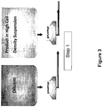
- the process comprises diluting the Pichia so that it is readily filtered (step 1), then filtering the diluted material in a first OPTISEP ® filter module via diafiltration so as to separate the product from the feed stock (step 2), while simultaneously: a) concentrating the permeate on a second OPTISEP ® filter module which both concentrates the product and recycles the diafiltration buffer (step 3) and b) concentrating the retentate of the first OPTISEP ® filter module with a third OPTISEP ® filter module recovering the diluent and returning the feed stock to its original volume or less (step 4).
- Typical P. pastoris fermentations can reach a wet cell weight of 50 to 60%. At these high solid concentrations, the culture typically must be diluted to permit effective passage during filtration.
- the dilution step 1 is depicted in Figure 3 and includes the following observations and or parameters:
- Step 2 once the culture is diluted; the cells are separated from the product in solution using an OPTISEP filter module with a microfiltration (MF) membrane.
- MF microfiltration
- the product passes through the MF membrane into the MF permeate by continuous diafiltration, as labeled in step 2 ( Figure 4 ) the cells remain in the recirculation loop, i.e. the retentate fluid.
- the MF membrane capacity is increased by adding more membrane area to the filter holder and/or more recirculation loops.
- the attached depiction of Figure 4 shows two (2) recirculation loops in series with one filter holder in each loop. Because the diafiltration is a steady state diafiltration, the volume entering the loop (i.e.
- the concentration step 2 includes the following observations and/or parameters:
- the third step is the concentration of the product derived from the MF permeate fluid as well as generating the diafiltration buffer.
- a second OPTISEP filter module containing an ultrafiltration (UF) membrane
- the permeate fluid of the MF membrane containing the product protein is concentrated.
- the product is concentrated in the retentate of this filter as depicted in Figure 5 .
- the UF permeate is recycled back to step 2 as the diafiltration buffer. This recycling dramatically lowers the waste produced from the system and decreases the operating expenses through the virtual elimination of buffers normally required for diafiltration.
- the concentration of the product includes the observations and/or parameters:
- the fourth and final step is the concentration of the cells back to their original concentration or a higher concentration using the third OPTISEP filter module with a UF membrane, step 4 ( Figure 6 ).
- the volume of cell waste is decreased.
- the recycle of the permeate dramatically lowers the waste produced from the system and decreases the operating expenses through the virtual elimination of the diluent needed to lower the concentration of the original fermentation broth.
- this step could be accomplished with an MF filter such that the number of diafiltration required in step 2 would be reduced and the permeate flow paths would be altered slightly from the attached slides.
- the concentration of the cells back to the original concentration includes the following observations and/or parameters:
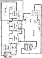
- Figure 7 shows the entire process without the various visual keys.
- experiment 1 The purpose of experiment 1 is to demonstrate the passage of the product away from the diluted cell suspension. Experiment 1 is performed at various dilution rates to optimize product recovery, minimize the rate of dilution and maximize the membrane performance in liters per meter square per hour (LMH).
- the starting material is diluted in a batch mode using different levels of diluent to determine the appropriate dilution and the product is separated from the diluted starting material via constant volume diafiltration. The level of diafiltration is determined.
- experiments 2 The purpose of experiments 2 is to concentrate the permeate of experiment 1.
- the permeate of experiment 1 contains the product which was separated from the cells by constant volume diafiltration of the cells.
- the permeate of the separation is concentrated in order to demonstrate recovery of the product and number of passes through MF for acceptable product concentration.
- experiments 3 is to concentrate the diafiltered retentate of experiment 1 in order to demonstrate the ability to return the cell mass to the original undiluted volume or less.
- the purpose of experiment 3 is to show the feasibility of reducing the volume of the process waste stream as well as the ability to recover the diluent.
- the diluted cellular material is concentrated to the original starting volume or less and number of passes through MF for acceptable concentration.
- Another embodiment for optimization comprises performing experiments 1, 2 and 3 utilizing three (3) different filtration steps (MF, UF of the MF permeate, and UF of cells); followed by a experiment 4 ( Figure 11 ) which is the simultaneous operation of the MF separation and the UF concentration of the MF permeate fluid
- Experiment 4 The purpose of Experiment 4 is the separation of the product from the cells by constant volume diafiltration while simultaneously concentrating the product such that the product is concentrated and the permeate of the product concentration is recycled as the diafiltration buffer.
- the diluted starting material is simultaneously separated and the product harvested via one MF and one UF membrane working simultaneously.
Landscapes
- Chemical & Material Sciences (AREA)
- Engineering & Computer Science (AREA)
- Water Supply & Treatment (AREA)
- Chemical Kinetics & Catalysis (AREA)
- Organic Chemistry (AREA)
- Biochemistry (AREA)
- Life Sciences & Earth Sciences (AREA)
- Biotechnology (AREA)
- General Health & Medical Sciences (AREA)
- Genetics & Genomics (AREA)
- Molecular Biology (AREA)
- Health & Medical Sciences (AREA)
- Separation Using Semi-Permeable Membranes (AREA)
- Soy Sauces And Products Related Thereto (AREA)
Claims (10)
- Ein Verfahren zur Aufreinigung von einer oder mehreren Zielsubstanzen aus einem viskosen Ausgangsmaterial, wobei genanntes Verfahren aufweist:In Kontakt bringen des viskosen Ausgangsmaterials mit einem Verdünnungsmittel in einer Menge, die ausreichend ist, die Viskosität des viskosen Ausgangsmaterials zu reduzieren und einen kontinuierlichen Strom von verdünntem Ausgangsmaterial zu bilden, wobei das Verdünnungsmittel in einem von dem viskosen Ausgangsmaterial (2) separaten Behältnis (1) ist;Einfließen lassen des verdünnten Ausgangsmaterials in eine Rückführungsschleife von einem ersten Cross-Flow Filter Apparat (4);Diafiltration des verdünnten Ausgangsmaterials mit ausreichend Diafiltration Puffer, der gehalten wird in einem Puffer Reservoir (7), um so die gewünschte Ausbeute von der Zielsubstanz wiederzugewinnen mittels Führen genannter Zielsubstanz in das erste Permeat Fluid;Fließen lassen des ersten Permeat Fluides, das die Zielsubstanz beinhaltet, zu einem Endproduktbehältnis (6);Ausfließen lassen der ersten Retentat Lösung aus der Rückführung Flüssigkeit von dem ersten Cross-Flow Filter (4) in eine zweite Cross-Flow Filter Einheit (5), wobei die Flussrate von der ersten Retentat Lösung bei der gleichen Flussrate ist wie das verdünnte Ausgangsmaterials, das in die Rückführungsschleife von dem ersten Cross-Flow Filter Apparat (4) eingegeben wird;Diafiltration des Flusses von Retentat in die zweite Cross-Flow Filter Einheit (5) mit ausreichend Diafiltration Puffer, um so die gewünschte Ausbeute von der Zielsubstanz wiederzugewinnen mittels Führen genannter Zielsubstanz in das zweite Permeat Fluid;Fließen lassen des zweiten Permeat Fluides, das die Zielsubstanz beinhaltet, zu dem Endproduktbehältnis (6);Aufkonzentrieren der ersten und zweiten Retentat Fluide mittels Fließen lassen derselben zu einem dritten Cross-Flow Filter Apparat (8), der kommunizierend verbunden ist mit der zweiten Cross-Flow Filter Einheit (5), wobei das Volumen des dritten Retentat Fluides reduziert wird auf das approximative Volumen von dem unverdünnten Ausgangsmaterial oder weniger, wodurch ein Abfallstrom zur weiteren Verwendung gebildet wird;Rückführen des dritten Permeat Fluides zurück zu dem Verdünnungsmittelbehältnis zur Wiederverwendung;Aufkonzentrieren des ersten und zweiten Permeat Fluides mittels Fließen lassen derselben zu einem vierten Cross-Flow Filter Apparat (9), der kommunizierend verbunden ist mit dem Endproduktbehältnis (6), wobei Zielsubstanzen aufkonzentriert wird und Diafiltration Puffer entfernt wird im vierten Permeat Strom und rückgeführt wird zurück zur Wiederverwendung.
- Das Verfahren gemäß Anspruch 1, wobei die Menge an Diafiltration Puffer eingeführt in das Puffer Reservoir (7) konserviert wird und zur Verfügung steht zur Wiederverwendung.
- Das Verfahren gemäß Anspruch 1, wobei das Verdünnungsmittel zurückgeleitet wird zu dem Verdünnungsmittelbehältnis gleichzeitig mit dem Aufkonzentrieren des Erzeugnis und der Zurückleitung des Puffers in das Prüfer Reservoir.
- Das Verfahren gemäß Anspruch 1, wobei die Cross-Flow filter (4, 5, 8, 9) aufweisen:eines multilaminiertes Array von Platten Elementen von im Wesentlichen rechteckiger und im Wesentlichen planarer Form mit oberen und unteren Hauptoberflächen, wobei die Platten Elemente in dem Array in Sequenz eine erste Retentat Platte, eine erste Filter Platte, eine Permeat Platte und eine zweite Filter Platte, und eine zweite Retentat Platte umfassen, wobei jedes von den Platten Elementen in dem Array wenigstens eine Einlass Becken Öffnung an einem Ende davon hat, und wenigstens eine Auslass Becken Öffnung an einem entgegengesetzten Ende davon hat, mit wenigsten einer Permeat Durchgang Öffnung an longitudinalen Seitenrandabschnitten von den Platten Elementen;jede von den ersten und zweiten Retentat Platten wenigstens eine Kanalöffnung darin hat, wobei jede Kanalöffnung sich longitudinal erstreckt zwischen den Einlass und der Auslass Becken Öffnungen von den Platten in dem Array und geöffnet ist entlang der vollständigen Dicke von der Retentat Platte, und wobei jede von der ersten und zweiten Retentat Platten gebunden ist an nebenan liegende Filterplatten, um periphere und seitliche Abschnitte davon, mit deren Beckenöffnungen und Permeat Durchgang Öffnungen, und in Register miteinander stehend, und ausgebildet sind, den Fluss von Filtrat durch die Kanalöffnungen von der Retentat Platte zwischen den Einlass und der Auslass Becken Öffnungen zu erlauben, um den Permeat Fluss durch die Filter Platte zu der Permeat Platte zu den Permeat Durchgang Öffnungen zu erlauben; unddie Cross-Flow Filter einen einheitlichen Artikel von zwischen gebundenen Platten Elementen aufweisen.
- Das Verfahren gemäß Anspruch 1, wobei das viskose Ausgangsmaterial eine Zellmasse ist und die Zielsubstanz ein Protein ist oder eine Fettsäure ist.
- Das Verfahren gemäß Anspruch 4, wobei das Cross-Flow Filtration Modul aufweist Kanal Höhe und Länge von der Retentat Platte zur optimalen Produktion Ausbeute.
- Das Verfahren gemäß Anspruch 1 ferner aufweisend den Schritt des Bestimmens der Menge von Verdünnungsmittel mittels Verdünnen einer Zellsuspension mit unterschiedlichen Verdünnung Mengen und Raten, um zu bestimmen die minimale Menge an Verdünnung, um die Menge an Endprodukt, die wieder gewonnen wird, zu maximieren.
- Das Verfahren gemäß Anspruch 7, ferner aufweisend das Bestimmen der Menge an Diafiltration Puffer, um Permeat aus der Zellsuspension zu separieren, wobei das Permeat das gewünschte Endprodukt umfasst.
- Das Verfahren gemäß Anspruch 8, ferner aufweisend das Bestimmen des Konzentrationsniveaus des Permeats, um die optimale Menge von gewünschtem Endprodukt wiederzugewinnen.
- Das Verfahren gemäß Anspruch 9, ferner aufweisend das Bestimmen des Konzentrationsniveaus des Retentats, um die optimale Menge von Zellmaterial zu der Konzentration von der ursprünglichen Zellsuspension zurückzugewinnen.
Applications Claiming Priority (3)
| Application Number | Priority Date | Filing Date | Title |
|---|---|---|---|
| US14614209P | 2009-01-21 | 2009-01-21 | |
| US14895909P | 2009-01-31 | 2009-01-31 | |
| PCT/US2010/021626 WO2010090864A2 (en) | 2009-01-21 | 2010-01-21 | Optimization of separation for viscous suspensions |
Publications (3)
| Publication Number | Publication Date |
|---|---|
| EP2393579A2 EP2393579A2 (de) | 2011-12-14 |
| EP2393579A4 EP2393579A4 (de) | 2013-07-03 |
| EP2393579B1 true EP2393579B1 (de) | 2017-03-08 |
Family
ID=42542592
Family Applications (1)
| Application Number | Title | Priority Date | Filing Date |
|---|---|---|---|
| EP10738945.4A Active EP2393579B1 (de) | 2009-01-21 | 2010-01-21 | Optimierte trennung viskoser suspensionen |
Country Status (4)
| Country | Link |
|---|---|
| US (2) | US8795530B2 (de) |
| EP (1) | EP2393579B1 (de) |
| CA (1) | CA2750263C (de) |
| WO (1) | WO2010090864A2 (de) |
Families Citing this family (27)
| Publication number | Priority date | Publication date | Assignee | Title |
|---|---|---|---|---|
| EP2393579B1 (de) * | 2009-01-21 | 2017-03-08 | Smartflow Technologies, Inc. | Optimierte trennung viskoser suspensionen |
| US9101883B2 (en) | 2009-11-28 | 2015-08-11 | Smartflow Technologies, Inc. | Portable filtration unit |
| US10005697B1 (en) | 2011-02-21 | 2018-06-26 | Smartflow Technologies, Inc. | Method and systems for isolation and/or separation of target products from animal produced waste streams |
| WO2012115932A2 (en) | 2011-02-21 | 2012-08-30 | Smartflow Technologies, Inc. | Method and systems for isolation and/or separation of products from production processes |
| US9670429B2 (en) | 2012-02-16 | 2017-06-06 | Smartflow Technologies, Inc. | Separation systems for dewatering of fog and biodiesel fuel production |
| EP2892636A4 (de) | 2012-09-06 | 2016-07-20 | Smartflow Technologies Inc | Permeatkanaländerungen für eine gegenstromfilterung zur verwendung in querströmungs-filterungsmodulen für osmosesysteme |
| US9511326B2 (en) | 2013-09-22 | 2016-12-06 | Spf Technologies Llc | Cycling ultra-thin channel filtration |
| US10518222B2 (en) | 2013-09-22 | 2019-12-31 | Spf Technologies, Llc | Cycling ultra-thin channel filtration |
| CN106457302B (zh) * | 2014-05-27 | 2020-04-17 | 人工细胞科技公司 | 通过tff进行多层涂覆芯的自动化逐层构造 |
| US10550148B2 (en) | 2014-06-16 | 2020-02-04 | Emd Millipore Corporation | Methods for increasing the capacity of flow-through processes |
| WO2015195452A2 (en) * | 2014-06-16 | 2015-12-23 | Emd Millipore Corporation | Single-pass filtration systems and processes |
| EP2957335B1 (de) * | 2014-06-16 | 2020-05-27 | EMD Millipore Corporation | Single-pass-filtersysteme und verfahren |
| EP4144434B1 (de) * | 2014-06-16 | 2024-04-17 | EMD Millipore Corporation | Single-pass-filtersysteme und -verfahren |
| CN115463546A (zh) | 2014-06-25 | 2022-12-13 | Emd 密理博公司 | 过滤器元件、切向流过滤系统、产生进料筛网的方法 |
| ES2935333T3 (es) | 2014-08-29 | 2023-03-06 | Emd Millipore Corp | Procesos para filtrar líquidos utilizando sistemas de filtración de flujo tangencial de paso único y sistemas de filtración de flujo tangencial con recirculación de retenido |
| CN105745009B (zh) | 2014-08-29 | 2018-09-28 | Emd 密理博公司 | 单程切向流过滤系统和具有渗余物的再循环的切向流过滤系统 |
| GB201600287D0 (en) | 2016-01-07 | 2016-02-24 | Fujifilm Diosynth Biotechnologies Uk Ltd | Process |
| GB201600290D0 (en) | 2016-01-07 | 2016-02-24 | Fujifilm Diosynth Biotechnologies Uk Ltd | Process |
| CA3023486C (en) | 2016-06-09 | 2022-03-29 | Emd Millipore Corporation | Radial-path filter elements, systems and methods of using same |
| EP3535047A1 (de) | 2016-12-09 | 2019-09-11 | Lonza Ltd | Verfahren zur reduktion des viralen titers in arzneimitteln |
| CN111246930B (zh) | 2017-11-13 | 2022-12-02 | Emd密理博公司 | 通过罐循环的连续透滤 |
| EP3781284B1 (de) | 2018-04-17 | 2024-08-07 | Smartflow Technologies, Inc. | Filterkassettenartikel und filter damit |
| ES2977655T3 (es) | 2018-05-17 | 2024-08-28 | Csl Behring Ag | Método y sistema de extracción de proteínas |
| US11241656B2 (en) * | 2018-11-29 | 2022-02-08 | Watersep Bioseparations Llc | Single pass cross flow diafiltration module and method |
| IT201900006432A1 (it) * | 2019-04-29 | 2020-10-29 | Hydra S R L | Dispositivo e procedimento per il trattamento di materiale biologico |
| AU2020307169A1 (en) * | 2019-06-28 | 2022-02-24 | Grafoid Inc. | Graphene based filters and systems comprising same |
| JP7513869B2 (ja) * | 2020-03-23 | 2024-07-10 | 澁谷工業株式会社 | エクソソーム抽出装置およびエクソソームの抽出方法 |
Family Cites Families (43)
| Publication number | Priority date | Publication date | Assignee | Title |
|---|---|---|---|---|
| US5356639A (en) | 1981-07-31 | 1994-10-18 | Commonwealth Scientific And Industrial Research Organization/Australian Dairy Corporation | Process for producing cheese containing substantially all the casein and whey proteins in milk |
| US4420398A (en) * | 1981-08-13 | 1983-12-13 | American National Red Cross | Filteration method for cell produced antiviral substances |
| US5593580A (en) | 1986-11-26 | 1997-01-14 | Kopf; Henry B. | Filtration cassette article, and filter comprising same |
| USD357059S (en) | 1994-03-01 | 1995-04-04 | Kopf Henry B | Flat sheet membrane mass transfer module |
| US5868930A (en) * | 1986-11-26 | 1999-02-09 | Kopf; Henry B. | Filtration cassette article and filter comprising same |
| US4885087A (en) | 1986-11-26 | 1989-12-05 | Kopf Henry B | Apparatus for mass transfer involving biological/pharmaceutical media |
| US6022742A (en) | 1986-11-26 | 2000-02-08 | Kopf; Henry B. | Culture device and method |
| CH672995A5 (de) * | 1987-07-27 | 1990-01-31 | Ciba Geigy Ag | |
| US5342517A (en) | 1987-10-02 | 1994-08-30 | Kopf Henry B | Filtration cassette article, and filter comprising same |
| US4867876A (en) | 1987-10-02 | 1989-09-19 | Kopf Henry B | Filter plate, filter plate element, and filter comprising same |
| US4882050A (en) | 1987-10-02 | 1989-11-21 | Kopf Henry B | Filter plate, filter plate element, and filter comprising same |
| US5049268A (en) | 1987-10-02 | 1991-09-17 | Kopf Henry B | Filter plate, filter plate element, and filter comprising same |
| US4956085A (en) | 1987-10-02 | 1990-09-11 | Kopf Henry B | Filter plate, filter plate element and filter comprising same |
| US5232589A (en) | 1987-10-02 | 1993-08-03 | Kopf Henry B | Filter element and support |
| USD324720S (en) | 1989-06-09 | 1992-03-17 | Kopf Henry B | Filter plate |
| USD323202S (en) | 1989-06-09 | 1992-01-14 | Kopf Henry B | Filter plate |
| USD325070S (en) | 1989-06-09 | 1992-03-31 | Kopf Henry B | Filter sheet |
| USD322117S (en) | 1989-09-01 | 1991-12-03 | Kopf Henry B | Filter plate |
| USD327313S (en) | 1989-09-01 | 1992-06-23 | Kopf Henry B | Filter plate |
| USD328789S (en) | 1990-03-01 | 1992-08-18 | Kopf Henry B | Filter sheet support element |
| DK168354B1 (da) * | 1991-05-21 | 1994-03-21 | Apv Pasilac As | Fremgangsmåde og anlæg til fremstilling af ost |
| DE4300921C1 (de) * | 1993-01-15 | 1994-04-14 | Hoechst Ag | Verfahren zur Lösungsmittel-Rückgewinnung sowie dafür geeignete Vorrichtung |
| US5597486A (en) * | 1995-05-01 | 1997-01-28 | Millipore Investment Holdings Limited | Membrane filtration with optimized addition of second liquid to maximize flux |
| AU756832B2 (en) * | 1999-02-22 | 2003-01-23 | Ncsrt, Inc. | Purification of biological substances |
| US6214221B1 (en) | 1999-02-22 | 2001-04-10 | Henry B. Kopf | Method and apparatus for purification of biological substances |
| US6875459B2 (en) | 2001-09-10 | 2005-04-05 | Henry B. Kopf | Method and apparatus for separation of milk, colostrum, and whey |
| US7270744B2 (en) * | 2001-10-09 | 2007-09-18 | Millipore Corporation | Automated low-volume tangential flow filtration process development device |
| CN100399930C (zh) * | 2002-07-29 | 2008-07-09 | 安敏诺技术公司 | 肽/氨基酸的生产方法、通过所述方法生产的肽/氨基酸及其应用 |
| CA2536039A1 (en) * | 2003-10-01 | 2005-04-14 | Campbell Soup Company | Process for enzymatic treatment and filtration of a plant and products obtainable thereby |
| JP4439526B2 (ja) * | 2004-02-18 | 2010-03-24 | ブーハー−グイアー・アクチェンゲゼルシャフト | 製品を完全濾過する方法とこの方法を実施する装置 |
| US8152999B2 (en) * | 2004-05-21 | 2012-04-10 | Wisconsin Alumni Research Foundation | Membrane cascade-based separation |
| WO2005113119A1 (en) * | 2004-05-21 | 2005-12-01 | Wisconsin Alumni Research Foundation | Membrane cascade-based separation |
| US20060051347A1 (en) * | 2004-09-09 | 2006-03-09 | Winter Charles M | Process for concentration of antibodies and therapeutic products thereof |
| AU2005229674B2 (en) | 2004-11-18 | 2010-11-04 | Kedrion Melville Inc. | Low concentration solvent/detergent process of immuneglobulin with pre-treatment |
| MX2007008777A (es) * | 2005-01-25 | 2007-10-23 | Wyeth Res Ireland Ltd | Metodo para diafiltracion. |
| US7510654B2 (en) * | 2005-12-29 | 2009-03-31 | Spf Innovations, Llc | Method and apparatus for the filtration of biological samples |
| US20070246406A1 (en) * | 2006-03-31 | 2007-10-25 | Dibel Kevin R | Tangential flow filtration apparatuses, systems, and processes for the separation of compounds |
| US20080017576A1 (en) * | 2006-06-15 | 2008-01-24 | Rensselaer Polytechnic Institute | Global model for optimizing crossflow microfiltration and ultrafiltration processes |
| JP4805201B2 (ja) | 2007-03-22 | 2011-11-02 | 月島環境エンジニアリング株式会社 | 膜分離を用いた目的物質の分離方法と装置 |
| US8231787B2 (en) * | 2008-05-06 | 2012-07-31 | Spf Innovations, Llc | Tangential flow filtration system |
| EP2393579B1 (de) * | 2009-01-21 | 2017-03-08 | Smartflow Technologies, Inc. | Optimierte trennung viskoser suspensionen |
| US20110195462A1 (en) * | 2010-02-08 | 2011-08-11 | Renewable Process Technologies, Llc | System and method for producing biomaterials |
| WO2012115932A2 (en) * | 2011-02-21 | 2012-08-30 | Smartflow Technologies, Inc. | Method and systems for isolation and/or separation of products from production processes |
-
2010
- 2010-01-21 EP EP10738945.4A patent/EP2393579B1/de active Active
- 2010-01-21 CA CA2750263A patent/CA2750263C/en active Active
- 2010-01-21 WO PCT/US2010/021626 patent/WO2010090864A2/en not_active Ceased
- 2010-01-21 US US13/144,967 patent/US8795530B2/en active Active
-
2014
- 2014-07-31 US US14/448,162 patent/US9745333B2/en active Active
Non-Patent Citations (1)
| Title |
|---|
| None * |
Also Published As
| Publication number | Publication date |
|---|---|
| EP2393579A2 (de) | 2011-12-14 |
| EP2393579A4 (de) | 2013-07-03 |
| CA2750263C (en) | 2018-03-20 |
| US9745333B2 (en) | 2017-08-29 |
| US20120205311A9 (en) | 2012-08-16 |
| WO2010090864A3 (en) | 2010-10-21 |
| US20150183815A1 (en) | 2015-07-02 |
| WO2010090864A2 (en) | 2010-08-12 |
| CA2750263A1 (en) | 2010-08-12 |
| US20110309018A1 (en) | 2011-12-22 |
| US8795530B2 (en) | 2014-08-05 |
Similar Documents
| Publication | Publication Date | Title |
|---|---|---|
| CA2750263C (en) | Optimization of separation for viscous suspensions | |
| US11633698B2 (en) | Method and apparatus for the filtration of biological solutions | |
| KR102462294B1 (ko) | 관류 적용을 위한 접선형 유동 여과 장치 | |
| WO2014039780A1 (en) | Permeate channel alterations for counter currant filtration for use in cross-flow filtration modules useful in osmotic systems | |
| EP4646284A1 (de) | Tangentialflussfilter mit kombinierten permeatausgängen und filterverfahren | |
| Kopf | Smart-FlowTM Technology: Optimizing Tangential Flow Filtration |
Legal Events
| Date | Code | Title | Description |
|---|---|---|---|
| PUAI | Public reference made under article 153(3) epc to a published international application that has entered the european phase |
Free format text: ORIGINAL CODE: 0009012 |
|
| 17P | Request for examination filed |
Effective date: 20110818 |
|
| AK | Designated contracting states |
Kind code of ref document: A2 Designated state(s): AT BE BG CH CY CZ DE DK EE ES FI FR GB GR HR HU IE IS IT LI LT LU LV MC MK MT NL NO PL PT RO SE SI SK SM TR |
|
| DAX | Request for extension of the european patent (deleted) | ||
| A4 | Supplementary search report drawn up and despatched |
Effective date: 20130603 |
|
| RIC1 | Information provided on ipc code assigned before grant |
Ipc: B01D 65/00 20060101ALI20130527BHEP Ipc: B01D 61/58 20060101AFI20130527BHEP |
|
| GRAP | Despatch of communication of intention to grant a patent |
Free format text: ORIGINAL CODE: EPIDOSNIGR1 |
|
| INTG | Intention to grant announced |
Effective date: 20161007 |
|
| GRAS | Grant fee paid |
Free format text: ORIGINAL CODE: EPIDOSNIGR3 |
|
| GRAA | (expected) grant |
Free format text: ORIGINAL CODE: 0009210 |
|
| AK | Designated contracting states |
Kind code of ref document: B1 Designated state(s): AT BE BG CH CY CZ DE DK EE ES FI FR GB GR HR HU IE IS IT LI LT LU LV MC MK MT NL NO PL PT RO SE SI SK SM TR |
|
| REG | Reference to a national code |
Ref country code: GB Ref legal event code: FG4D |
|
| REG | Reference to a national code |
Ref country code: CH Ref legal event code: EP Ref country code: AT Ref legal event code: REF Ref document number: 873021 Country of ref document: AT Kind code of ref document: T Effective date: 20170315 |
|
| REG | Reference to a national code |
Ref country code: IE Ref legal event code: FG4D |
|
| REG | Reference to a national code |
Ref country code: DE Ref legal event code: R096 Ref document number: 602010040582 Country of ref document: DE |
|
| REG | Reference to a national code |
Ref country code: LT Ref legal event code: MG4D |
|
| REG | Reference to a national code |
Ref country code: NL Ref legal event code: MP Effective date: 20170308 |
|
| PG25 | Lapsed in a contracting state [announced via postgrant information from national office to epo] |
Ref country code: NO Free format text: LAPSE BECAUSE OF FAILURE TO SUBMIT A TRANSLATION OF THE DESCRIPTION OR TO PAY THE FEE WITHIN THE PRESCRIBED TIME-LIMIT Effective date: 20170608 Ref country code: FI Free format text: LAPSE BECAUSE OF FAILURE TO SUBMIT A TRANSLATION OF THE DESCRIPTION OR TO PAY THE FEE WITHIN THE PRESCRIBED TIME-LIMIT Effective date: 20170308 Ref country code: GR Free format text: LAPSE BECAUSE OF FAILURE TO SUBMIT A TRANSLATION OF THE DESCRIPTION OR TO PAY THE FEE WITHIN THE PRESCRIBED TIME-LIMIT Effective date: 20170609 Ref country code: LT Free format text: LAPSE BECAUSE OF FAILURE TO SUBMIT A TRANSLATION OF THE DESCRIPTION OR TO PAY THE FEE WITHIN THE PRESCRIBED TIME-LIMIT Effective date: 20170308 Ref country code: HR Free format text: LAPSE BECAUSE OF FAILURE TO SUBMIT A TRANSLATION OF THE DESCRIPTION OR TO PAY THE FEE WITHIN THE PRESCRIBED TIME-LIMIT Effective date: 20170308 |
|
| REG | Reference to a national code |
Ref country code: AT Ref legal event code: MK05 Ref document number: 873021 Country of ref document: AT Kind code of ref document: T Effective date: 20170308 |
|
| PG25 | Lapsed in a contracting state [announced via postgrant information from national office to epo] |
Ref country code: ES Free format text: LAPSE BECAUSE OF FAILURE TO SUBMIT A TRANSLATION OF THE DESCRIPTION OR TO PAY THE FEE WITHIN THE PRESCRIBED TIME-LIMIT Effective date: 20170308 Ref country code: SE Free format text: LAPSE BECAUSE OF FAILURE TO SUBMIT A TRANSLATION OF THE DESCRIPTION OR TO PAY THE FEE WITHIN THE PRESCRIBED TIME-LIMIT Effective date: 20170308 Ref country code: BG Free format text: LAPSE BECAUSE OF FAILURE TO SUBMIT A TRANSLATION OF THE DESCRIPTION OR TO PAY THE FEE WITHIN THE PRESCRIBED TIME-LIMIT Effective date: 20170608 Ref country code: LV Free format text: LAPSE BECAUSE OF FAILURE TO SUBMIT A TRANSLATION OF THE DESCRIPTION OR TO PAY THE FEE WITHIN THE PRESCRIBED TIME-LIMIT Effective date: 20170308 |
|
| PG25 | Lapsed in a contracting state [announced via postgrant information from national office to epo] |
Ref country code: NL Free format text: LAPSE BECAUSE OF FAILURE TO SUBMIT A TRANSLATION OF THE DESCRIPTION OR TO PAY THE FEE WITHIN THE PRESCRIBED TIME-LIMIT Effective date: 20170308 |
|
| PG25 | Lapsed in a contracting state [announced via postgrant information from national office to epo] |
Ref country code: SK Free format text: LAPSE BECAUSE OF FAILURE TO SUBMIT A TRANSLATION OF THE DESCRIPTION OR TO PAY THE FEE WITHIN THE PRESCRIBED TIME-LIMIT Effective date: 20170308 Ref country code: RO Free format text: LAPSE BECAUSE OF FAILURE TO SUBMIT A TRANSLATION OF THE DESCRIPTION OR TO PAY THE FEE WITHIN THE PRESCRIBED TIME-LIMIT Effective date: 20170308 Ref country code: CZ Free format text: LAPSE BECAUSE OF FAILURE TO SUBMIT A TRANSLATION OF THE DESCRIPTION OR TO PAY THE FEE WITHIN THE PRESCRIBED TIME-LIMIT Effective date: 20170308 Ref country code: EE Free format text: LAPSE BECAUSE OF FAILURE TO SUBMIT A TRANSLATION OF THE DESCRIPTION OR TO PAY THE FEE WITHIN THE PRESCRIBED TIME-LIMIT Effective date: 20170308 Ref country code: AT Free format text: LAPSE BECAUSE OF FAILURE TO SUBMIT A TRANSLATION OF THE DESCRIPTION OR TO PAY THE FEE WITHIN THE PRESCRIBED TIME-LIMIT Effective date: 20170308 |
|
| PG25 | Lapsed in a contracting state [announced via postgrant information from national office to epo] |
Ref country code: PL Free format text: LAPSE BECAUSE OF FAILURE TO SUBMIT A TRANSLATION OF THE DESCRIPTION OR TO PAY THE FEE WITHIN THE PRESCRIBED TIME-LIMIT Effective date: 20170308 Ref country code: SM Free format text: LAPSE BECAUSE OF FAILURE TO SUBMIT A TRANSLATION OF THE DESCRIPTION OR TO PAY THE FEE WITHIN THE PRESCRIBED TIME-LIMIT Effective date: 20170308 Ref country code: IS Free format text: LAPSE BECAUSE OF FAILURE TO SUBMIT A TRANSLATION OF THE DESCRIPTION OR TO PAY THE FEE WITHIN THE PRESCRIBED TIME-LIMIT Effective date: 20170708 Ref country code: PT Free format text: LAPSE BECAUSE OF FAILURE TO SUBMIT A TRANSLATION OF THE DESCRIPTION OR TO PAY THE FEE WITHIN THE PRESCRIBED TIME-LIMIT Effective date: 20170710 |
|
| REG | Reference to a national code |
Ref country code: DE Ref legal event code: R097 Ref document number: 602010040582 Country of ref document: DE |
|
| PLBE | No opposition filed within time limit |
Free format text: ORIGINAL CODE: 0009261 |
|
| STAA | Information on the status of an ep patent application or granted ep patent |
Free format text: STATUS: NO OPPOSITION FILED WITHIN TIME LIMIT |
|
| REG | Reference to a national code |
Ref country code: FR Ref legal event code: PLFP Year of fee payment: 9 |
|
| PG25 | Lapsed in a contracting state [announced via postgrant information from national office to epo] |
Ref country code: DK Free format text: LAPSE BECAUSE OF FAILURE TO SUBMIT A TRANSLATION OF THE DESCRIPTION OR TO PAY THE FEE WITHIN THE PRESCRIBED TIME-LIMIT Effective date: 20170308 |
|
| 26N | No opposition filed |
Effective date: 20171211 |
|
| PG25 | Lapsed in a contracting state [announced via postgrant information from national office to epo] |
Ref country code: SI Free format text: LAPSE BECAUSE OF FAILURE TO SUBMIT A TRANSLATION OF THE DESCRIPTION OR TO PAY THE FEE WITHIN THE PRESCRIBED TIME-LIMIT Effective date: 20170308 Ref country code: IT Free format text: LAPSE BECAUSE OF FAILURE TO SUBMIT A TRANSLATION OF THE DESCRIPTION OR TO PAY THE FEE WITHIN THE PRESCRIBED TIME-LIMIT Effective date: 20170308 |
|
| REG | Reference to a national code |
Ref country code: CH Ref legal event code: PL |
|
| PG25 | Lapsed in a contracting state [announced via postgrant information from national office to epo] |
Ref country code: LU Free format text: LAPSE BECAUSE OF NON-PAYMENT OF DUE FEES Effective date: 20180121 |
|
| REG | Reference to a national code |
Ref country code: IE Ref legal event code: MM4A |
|
| REG | Reference to a national code |
Ref country code: BE Ref legal event code: MM Effective date: 20180131 |
|
| PG25 | Lapsed in a contracting state [announced via postgrant information from national office to epo] |
Ref country code: LI Free format text: LAPSE BECAUSE OF NON-PAYMENT OF DUE FEES Effective date: 20180131 Ref country code: BE Free format text: LAPSE BECAUSE OF NON-PAYMENT OF DUE FEES Effective date: 20180131 Ref country code: CH Free format text: LAPSE BECAUSE OF NON-PAYMENT OF DUE FEES Effective date: 20180131 |
|
| PG25 | Lapsed in a contracting state [announced via postgrant information from national office to epo] |
Ref country code: IE Free format text: LAPSE BECAUSE OF NON-PAYMENT OF DUE FEES Effective date: 20180121 |
|
| PG25 | Lapsed in a contracting state [announced via postgrant information from national office to epo] |
Ref country code: MC Free format text: LAPSE BECAUSE OF FAILURE TO SUBMIT A TRANSLATION OF THE DESCRIPTION OR TO PAY THE FEE WITHIN THE PRESCRIBED TIME-LIMIT Effective date: 20170308 |
|
| PG25 | Lapsed in a contracting state [announced via postgrant information from national office to epo] |
Ref country code: MT Free format text: LAPSE BECAUSE OF NON-PAYMENT OF DUE FEES Effective date: 20180121 |
|
| PG25 | Lapsed in a contracting state [announced via postgrant information from national office to epo] |
Ref country code: TR Free format text: LAPSE BECAUSE OF FAILURE TO SUBMIT A TRANSLATION OF THE DESCRIPTION OR TO PAY THE FEE WITHIN THE PRESCRIBED TIME-LIMIT Effective date: 20170308 |
|
| PG25 | Lapsed in a contracting state [announced via postgrant information from national office to epo] |
Ref country code: HU Free format text: LAPSE BECAUSE OF FAILURE TO SUBMIT A TRANSLATION OF THE DESCRIPTION OR TO PAY THE FEE WITHIN THE PRESCRIBED TIME-LIMIT; INVALID AB INITIO Effective date: 20100121 |
|
| PG25 | Lapsed in a contracting state [announced via postgrant information from national office to epo] |
Ref country code: MK Free format text: LAPSE BECAUSE OF NON-PAYMENT OF DUE FEES Effective date: 20170308 Ref country code: CY Free format text: LAPSE BECAUSE OF FAILURE TO SUBMIT A TRANSLATION OF THE DESCRIPTION OR TO PAY THE FEE WITHIN THE PRESCRIBED TIME-LIMIT Effective date: 20170308 |
|
| P01 | Opt-out of the competence of the unified patent court (upc) registered |
Effective date: 20230601 |
|
| PGFP | Annual fee paid to national office [announced via postgrant information from national office to epo] |
Ref country code: GB Payment date: 20260127 Year of fee payment: 17 |
|
| PGFP | Annual fee paid to national office [announced via postgrant information from national office to epo] |
Ref country code: DE Payment date: 20260128 Year of fee payment: 17 |
|
| PGFP | Annual fee paid to national office [announced via postgrant information from national office to epo] |
Ref country code: FR Payment date: 20260126 Year of fee payment: 17 |