EP2393079A1 - Outdoor display system and display apparatus - Google Patents
Outdoor display system and display apparatus Download PDFInfo
- Publication number
- EP2393079A1 EP2393079A1 EP11168226A EP11168226A EP2393079A1 EP 2393079 A1 EP2393079 A1 EP 2393079A1 EP 11168226 A EP11168226 A EP 11168226A EP 11168226 A EP11168226 A EP 11168226A EP 2393079 A1 EP2393079 A1 EP 2393079A1
- Authority
- EP
- European Patent Office
- Prior art keywords
- solar cell
- display
- display panel
- contents
- control unit
- Prior art date
- Legal status (The legal status is an assumption and is not a legal conclusion. Google has not performed a legal analysis and makes no representation as to the accuracy of the status listed.)
- Withdrawn
Links
Images

Classifications
-
- G—PHYSICS
- G09—EDUCATION; CRYPTOGRAPHY; DISPLAY; ADVERTISING; SEALS
- G09F—DISPLAYING; ADVERTISING; SIGNS; LABELS OR NAME-PLATES; SEALS
- G09F19/00—Advertising or display means not otherwise provided for
- G09F19/22—Advertising or display means on roads, walls or similar surfaces, e.g. illuminated
-
- G—PHYSICS
- G09—EDUCATION; CRYPTOGRAPHY; DISPLAY; ADVERTISING; SEALS
- G09F—DISPLAYING; ADVERTISING; SIGNS; LABELS OR NAME-PLATES; SEALS
- G09F13/00—Illuminated signs; Luminous advertising
- G09F13/04—Signs, boards or panels, illuminated from behind the insignia
-
- G—PHYSICS
- G09—EDUCATION; CRYPTOGRAPHY; DISPLAY; ADVERTISING; SEALS
- G09F—DISPLAYING; ADVERTISING; SIGNS; LABELS OR NAME-PLATES; SEALS
- G09F13/00—Illuminated signs; Luminous advertising
- G09F13/20—Illuminated signs; Luminous advertising with luminescent surfaces or parts
- G09F13/22—Illuminated signs; Luminous advertising with luminescent surfaces or parts electroluminescent
-
- G—PHYSICS
- G09—EDUCATION; CRYPTOGRAPHY; DISPLAY; ADVERTISING; SEALS
- G09F—DISPLAYING; ADVERTISING; SIGNS; LABELS OR NAME-PLATES; SEALS
- G09F23/00—Advertising on or in specific articles, e.g. ashtrays, letter-boxes
-
- G—PHYSICS
- G09—EDUCATION; CRYPTOGRAPHY; DISPLAY; ADVERTISING; SEALS
- G09F—DISPLAYING; ADVERTISING; SIGNS; LABELS OR NAME-PLATES; SEALS
- G09F27/00—Combined visual and audible advertising or displaying, e.g. for public address
-
- G—PHYSICS
- G09—EDUCATION; CRYPTOGRAPHY; DISPLAY; ADVERTISING; SEALS
- G09F—DISPLAYING; ADVERTISING; SIGNS; LABELS OR NAME-PLATES; SEALS
- G09F27/00—Combined visual and audible advertising or displaying, e.g. for public address
- G09F27/007—Displays with power supply provided by solar cells or photocells
-
- G—PHYSICS
- G09—EDUCATION; CRYPTOGRAPHY; DISPLAY; ADVERTISING; SEALS
- G09F—DISPLAYING; ADVERTISING; SIGNS; LABELS OR NAME-PLATES; SEALS
- G09F9/00—Indicating arrangements for variable information in which the information is built-up on a support by selection or combination of individual elements
- G09F9/30—Indicating arrangements for variable information in which the information is built-up on a support by selection or combination of individual elements in which the desired character or characters are formed by combining individual elements
- G09F9/35—Indicating arrangements for variable information in which the information is built-up on a support by selection or combination of individual elements in which the desired character or characters are formed by combining individual elements being liquid crystals
Definitions
- the present invention relates to an outdoor display system or a display apparatus. Specifically, the system equips a power generator such as a solar cell, and is suitable when employed as bus stop etc..
- digital signage In recent years, an advertising media called digital signage is appearing.
- images or information are displayed on a flat-panel display using a digital technology.
- digital signage apparatus is utilized in facilities such as bus stops.
- the outdoor display system has a solar cell; an electricity storing unit which stores electricity obtained by the solar cell, and a display apparatus having a displaying portion displaying contents, wherein the apparatus is supplied an electric power from the storing unit or the solar cell.
- Fig. 1 is an outline view of the outdoor display system 10 which is an embodiment of the present invention.
- the outdoor display system 10 has a solar cell 1, a secondary battery 2, a display apparatus 3, a poster 4, a bench (seat) 5, and a roof 6.
- a solar cell 1 a secondary battery 2
- a display apparatus 3 a poster 4
- a bench (seat) 5 a roof 6.
- the human sensor 33 and a camera sensor 34 are arranged on the surface of the display apparatus 3.
- the solar cell 1 generates electricity by photo-electric converting the sunlight.
- the cell 1 includes a solar cell module consisted by solar array panels etc., and the inverter.
- the electric power obtained by the solar cell 1 is stored in the battery 2.
- the secondary battery 2 is a lithium-ion battery (battery pack), for example. Between the cell 1 and the battery 2, an inverter or controller controlling the charging or discharging in the battery 2 may intervene in between.
- the display apparatus 3 is a LCD display equipped with a display panel 32 such as a Liquid Crystal Panel (LCD).
- the apparatus 3 displays contents (images) transmitted from an external contents server or a broadcasting station, or contents stored in a supplemental (add-on) storage devices.
- the apparatus 3 displays a route map of the bus, a operating situation (for example, the arrival information of a bus at a neighboring bus stop) etc.
- the apparatus 3 has an antenna (contained in the receiving portion 35 mentioned below) for receiving contents transmitted wireless.
- the apparatus 3 is driven by electricity generated by the solar cell 1, and does not require electric power from a power line.
- the display apparatus 3 operates in "off-grid".
- the electric construction for drawing electric power from the power line is not necessary.
- equipping an antenna it is unnecessary to install the cable for connecting to a LAN or WAN networks to receive contents data.
- this outdoor display system 10 mitigates the burden of installation, and should contribute for marketing (sale or wide use) of the digital signage systems.
- the human sensor 33 and the camera sensor 34 are arranged.
- the human sensor 33 is for detecting an existence of a person in the bus stop, and for example, an infrared sensor is used.
- the display apparatus 3 reduces the illumination of the backlight 39, or turns the backlight 39 off. Thereby, the electric power is reduced.
- the camera sensor 34 determines an attributes of a person in the bus stop based on photographed images. When determined that a person is female, for example, an advertisement of cosmetics may be displayed. When it is determined male, an advertisement of beer may be displayed.
- a poster 4 comprises an advertising film which transmits a light and advertisement is printed thereon, and a fluorescent light which irradiates the film from the inner side (side opposite from the displaying side).
- the poster 4 is similar to the display apparatus 3 in sense that it displays an advertisement. However, the image displayed in the apparatus 3 changes every moment according to the received contents (i.e. if the contents is a moving image, the displaying image changes every seconds), while the image displayed in the poster 4 does not change basically since the poster displays a printed advertisement.
- a bench 5 is arranged for a person in the bus stop, so that a person can sit down while waiting for the bus, and is arranged in the front side of the display apparatus 3.
- the display apparatus 3 installed on the sidewalk and facing its backside to the street (driveway)
- a person sitting on the bench 5 is to be waiting for the bus while watching the advertising contents displayed on the apparatus 3.
- the display apparatus 3 is installed facing its displaying side to the street (driveway)
- a passenger in the bus, a person in a car driving down the street, or a person on the sidewalk on the opposite side of the street can watch the advertising contents displayed on the apparatus 3.
- a person sitting on the bench 5 can watch advertising contents if he turns his back to the street too.
- the roof 6 is arranged above the display apparatus 3 and functions as a shade or a rain-cover for the apparatus 3. Also it covers a person waiting for the bus.
- the solar cell 1 or the secondary battery 2 is arranged, thus the roof 6 functions as installation stands also.
- the surface of the cell 1 is inclined against the roof 6.
- the battery 2 may be arranged between the cell 1 and the roof 6, utilizing a triangular prism-like space occurred by the inclined roof 6.
- Fig.2 is a block diagram showing the composition of the outdoor display system 10.
- the system 10 has a solar cell 1, a secondary battery 2, and a display apparatus 3.
- the apparatus 3 has a control unit 31, a display panel 32, a human sensor 33, a camera sensor 34, a receiving unit 35, a storage unit 36, a display control unit 37, a power supply circuit 38, a backlight 39, and a touch panel 40.
- the electric power generated by the solar cell 1 is stored in the secondary battery 2.
- the solar cell 1 transmits the information regarding to power generating condition to the display apparatus 3.
- the battery 2 supplies electric power to the apparatus 3.
- the battery 2 transmits its residual capacity information.
- the display apparatus 3 of the present embodiment does not basically receive electric power supply from a power line, and operates as "off-grid".
- the capability of the solar cell 1 should be selected or designed considering the power consumption of the display apparatus 3. First, the electric-generating capacity required for the solar cell should be determined based on the amount of power consumption in the apparatus 3. Then, of the size (surface area) of the cell should be determined considering the power generating efficiency of the solar cell 1.
- the capacity of the secondary battery 2 should be determined considering the case when sunlight does not glare, such as rainy weather or night time.
- the control unit 31 collects the state information of each portion (i.e. the display panel 32, the touch panel 40 etc.) of the display apparatus 3. The unit 31 controls each of the portions based on the collected information. The power generating status information from the solar cell 1 or the residual capacity information from the secondary battery 2 are also inputted to the control unit 31.
- the unit 31 is constituted by CPU.
- the display panel 32 is a portion which actually displays an image, and an LCD panel is employed for display apparatus 3.
- liquid crystal corresponding to each pixel of the panel is driven between ON/OFF state (or to intermediate state).
- the human sensor 33 is for detecting the person's existence in the bus stop as described above.
- the camera sensor 34 is for determining the characteristic of the person in the bus stop.
- the sensors 33 and 34 are connected with the control unit 31, and the detected results in these sensors are inputted to the unit 31.
- the receiving part 35 has an antenna which receives a signal from contents server (for example, ASP server, or personal computer) transmitted by wireless networks (for example, WiMAX or IEEE802.1 1b/g), and a signal-processing unit which demodulates the signal received by the antenna.
- contents server for example, ASP server, or personal computer
- wireless networks for example, WiMAX or IEEE802.1 1b/g
- the unit 35 demodulates the OFDM signal and then extracts the MPEG 2-TS signal.
- the extracted MPEG 2-TS signal is outputted to the storage unit 36.
- the unit 35 may also have a function for receiving a broadcast wave from a television broadcasting station, like an ordinary television does.
- the storage unit 36 stores a MPEG 2-TS signal extracted by the receiving unit 35. In other words, the unit 36 stores the contents transmitted from contents server or broadcasting station. If the content is real-time type content (which is displayed by the display panel 32 immediately after the reception in the receiving unit 35), the storage unit 36 functions as a buffer memory. If the content is storage-type contents (which is displayed according to the operation of a user or displayed based on a time schedule), the storage unit 36 functions as storage media.
- the display control unit 37 performs a display control in the display panel 32. Specifically, according to the image signal of the contents, the unit 37 controls the corresponding pixels of the display panel 32 (LCD panel). Since the unit 37 needs to perform a high-speed processing, hardware circuit provided independently from the control unit 31 (constituted by CPU) is utilized.
- the power supply circuit 38 supplies power to each portion of the display apparatus 3. Based on an assumption that the power consumption in the display panel 32 and the backlight 39 is larger than the other portions, it is described in Fig. 2 such that the power is supplied only to the panel 32 and the backlight 39. However, the power supply circuit 38 actually supplies electric power to the receiving unit 35, the storing unit 36, the display control unit 37, the human sensor 33, the camera sensor 34, and the touch panel 40 as well.
- the backlight 39 irradiates a light to the display panel 32.
- fluorescent light or an LED light source is used for example. Since the display apparatus 3 of the present embodiment is used in "off-grid" mode, it is desired that the power consumption is low. In this view, LED light source may be desirable.
- the touch panel 40 is transparent and is an electric capacity-type touch sensor. This touch panel 40 is arranged at the front side of the display panel 32.
- the touch panel 40 accepts an input from a user. For example, when the display panel 32 displays the image of buttons for accepting the user to make selection out of three choices, it regards the input is made by a user when the user touches a position corresponding to the button image.
- Fig. 3 is a flow chart showing an example of a displaying process performed by the display apparatus 3. Since various kinds of displaying processes are provided in the displaying apparatus 3, here, it is focused on a displaying process adapted to a residual capacity of the secondary battery 2 which is a process peculiar to the present invention.
- Step S1 the control unit 31 checks the residual capacity R based on an information inputted from the secondary battery 2. In the Step S2, it is determined whether the R is less than the predetermined capacity R TH or not. When the R is equal to or larger than the R TH (when determined “no" in Step S2), since the residual capacity of the battery 2 is large enough, the ordinal luminosity control is performed. In other word, the luminosity of the backlight is set to a standard value. When R is less than R TH (when determined "yes" at Step S2), it proceeds to Step S3.
- Step S3 the control unit 31 checks the current amount of generated electricity P based on the input from the solar cell 1.
- Step S4 it is determined whether the P is larger than the predetermined value P TH or not.
- P is larger than P TH (when it is determined "yes” in Step S4), it is in a state the sun is irradiating, and the solar cell 1 is in a power generating state. Therefore, assuming that the electricity stored in the storage battery 2 will not vanish because the solar cell 1 is in a power generating state even though the residual capacity of the battery 2 is small, the ordinal luminosity control is performed.
- Step S4 when the sunlight is not irradiating (for example, nighttime, cloudy, or rainy weather), P becomes smaller than P TH (in such case, it is determined "no" in Step S4). Nonetheless, if the display apparatus 3 is kept on driving, the residual capacity of the secondary battery 2 becomes zero at some time-point. Thus, the luminosity of the backlight is set lower than the standard setting in order to save the power consumption.
- the luminosity controlling process of the display apparatus 3 is not restricted to the one mentioned in the above flowchart.
- the contrast degrades because of the sunlight, and the visibility of the display panel 32 falls, thus the luminosity of the backlight 39 may be set high in the daytime.
- the contrast becomes large, thus luminosity of the backlight 39 may be set low.
- the luminosity of the backlight 39 can be controlled according to the outdoor temperature.
- the luminosity of the backlight 39 may be controlled low, when the outdoor temperature is high. Further, the luminosity of the backlight 39 may be controlled low even though when the outside temperature is low, if the temperature inside the housing of the display apparatus 3 is high.
- two sensors i.e. the human sensor 33 and the camera sensor 34 are employed; however, the camera sensor 34 may also function as a human sensor. In such case, existence of a person is detected from a captured image instead of using infrared rays done by human sensor 33.
- an LCD panel is explained as an example of the display portion of the display apparatus 3; however, plasma panel, organic EL (Electro-Luminescence), electronic paper, CRT, or an advertising film may be employed as the display portion instead.
- plasma panel organic EL (Electro-Luminescence), electronic paper, CRT, or an advertising film may be employed as the display portion instead.
- the luminosity control of the apparatus 3 is achieved by the control part 31, however, this control may be performed by a dedicated control apparatus, which is separated (or independent) from the apparatus 3.
- the electric power generated by the cell 1 may be supplied directly to the display apparatus 3.
- a control device may be arranged between the solar cell 1, the secondary battery 2, and the display apparatus 3. This control device compares the amount of generated electricity in the solar cell 1 and the power consumption of the display apparatus 3 and if the generated amount is larger than the consumption, the surplus electric power may be charged by the secondary battery 2. When the generated electricity is smaller than the power consumption, the electricity stored in the battery 2 may be utilized in the display apparatus 3.
- the secondary battery 2 is arranged on the roof 6 as well as the solar cell 1.
- the battery 2 may be arranged under the roof 6, or under the display apparatus 3.
Landscapes
- Physics & Mathematics (AREA)
- General Physics & Mathematics (AREA)
- Engineering & Computer Science (AREA)
- Theoretical Computer Science (AREA)
- Chemical & Material Sciences (AREA)
- Sustainable Development (AREA)
- Life Sciences & Earth Sciences (AREA)
- Crystallography & Structural Chemistry (AREA)
- Business, Economics & Management (AREA)
- Accounting & Taxation (AREA)
- Marketing (AREA)
- Devices For Indicating Variable Information By Combining Individual Elements (AREA)
- Controls And Circuits For Display Device (AREA)
- Two-Way Televisions, Distribution Of Moving Picture Or The Like (AREA)
Abstract
Description
- The present invention relates to an outdoor display system or a display apparatus. Specifically, the system equips a power generator such as a solar cell, and is suitable when employed as bus stop etc..
- In recent years, an advertising media called digital signage is appearing. In the digital signage, images or information are displayed on a flat-panel display using a digital technology. Such digital signage apparatus is utilized in facilities such as bus stops.
- However, when installing digital signage displays outdoors, since electric power needs to be supplied from a power line, besides installation works, electric construction is further needed. This is one of the obstacles when marketing the digital signage apparatuses.
- The outdoor display system according to the present invention has a solar cell; an electricity storing unit which stores electricity obtained by the solar cell, and a display apparatus having a displaying portion displaying contents, wherein the apparatus is supplied an electric power from the storing unit or the solar cell.
-
-
Fig.1 is an outline view of theoutdoor display system 10. -
Fig.2 is a block diagram showing a composition of theoutdoor display system 10. -
Fig.3 is a flow chart showing an example of the displaying process executed by thedisplay apparatus 3. -
Fig. 1 is an outline view of theoutdoor display system 10 which is an embodiment of the present invention. - The
outdoor display system 10 has asolar cell 1, asecondary battery 2, adisplay apparatus 3, aposter 4, a bench (seat) 5, and aroof 6. On the surface of thedisplay apparatus 3, thehuman sensor 33 and acamera sensor 34 are arranged. - The
solar cell 1 generates electricity by photo-electric converting the sunlight. Here, thecell 1 includes a solar cell module consisted by solar array panels etc., and the inverter. The electric power obtained by thesolar cell 1 is stored in thebattery 2. Thesecondary battery 2 is a lithium-ion battery (battery pack), for example. Between thecell 1 and thebattery 2, an inverter or controller controlling the charging or discharging in thebattery 2 may intervene in between. - The
display apparatus 3 is a LCD display equipped with adisplay panel 32 such as a Liquid Crystal Panel (LCD). Theapparatus 3 displays contents (images) transmitted from an external contents server or a broadcasting station, or contents stored in a supplemental (add-on) storage devices. When installed in a bus stop, theapparatus 3 displays a route map of the bus, a operating situation (for example, the arrival information of a bus at a neighboring bus stop) etc. - Further, in the present embodiment, the
apparatus 3 has an antenna (contained in the receivingportion 35 mentioned below) for receiving contents transmitted wireless. - As described above, the
apparatus 3 is driven by electricity generated by thesolar cell 1, and does not require electric power from a power line. In other words, thedisplay apparatus 3 operates in "off-grid". Thus, the electric construction for drawing electric power from the power line is not necessary. Further, by equipping an antenna, it is unnecessary to install the cable for connecting to a LAN or WAN networks to receive contents data. Thereby, thisoutdoor display system 10 mitigates the burden of installation, and should contribute for marketing (sale or wide use) of the digital signage systems. - In the lower part surface of an image displaying portion of the
display apparatus 3, thehuman sensor 33 and thecamera sensor 34 are arranged. - The
human sensor 33 is for detecting an existence of a person in the bus stop, and for example, an infrared sensor is used. When thesensor 33 determines that a person does not exist, thedisplay apparatus 3 reduces the illumination of thebacklight 39, or turns thebacklight 39 off. Thereby, the electric power is reduced. - The
camera sensor 34 determines an attributes of a person in the bus stop based on photographed images. When determined that a person is female, for example, an advertisement of cosmetics may be displayed. When it is determined male, an advertisement of beer may be displayed. - A
poster 4 comprises an advertising film which transmits a light and advertisement is printed thereon, and a fluorescent light which irradiates the film from the inner side (side opposite from the displaying side). Theposter 4 is similar to thedisplay apparatus 3 in sense that it displays an advertisement. However, the image displayed in theapparatus 3 changes every moment according to the received contents (i.e. if the contents is a moving image, the displaying image changes every seconds), while the image displayed in theposter 4 does not change basically since the poster displays a printed advertisement. - A
bench 5 is arranged for a person in the bus stop, so that a person can sit down while waiting for the bus, and is arranged in the front side of thedisplay apparatus 3. When thedisplay apparatus 3 installed on the sidewalk and facing its backside to the street (driveway), a person sitting on thebench 5 is to be waiting for the bus while watching the advertising contents displayed on theapparatus 3. When thedisplay apparatus 3 is installed facing its displaying side to the street (driveway), a passenger in the bus, a person in a car driving down the street, or a person on the sidewalk on the opposite side of the street can watch the advertising contents displayed on theapparatus 3. Needless to say, a person sitting on thebench 5 can watch advertising contents if he turns his back to the street too. - The
roof 6 is arranged above thedisplay apparatus 3 and functions as a shade or a rain-cover for theapparatus 3. Also it covers a person waiting for the bus. On theroof 6, thesolar cell 1 or thesecondary battery 2 is arranged, thus theroof 6 functions as installation stands also. Considering the direction of the sunlight, the surface of thecell 1 is inclined against theroof 6. Thebattery 2 may be arranged between thecell 1 and theroof 6, utilizing a triangular prism-like space occurred by theinclined roof 6. -
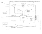
Fig.2 is a block diagram showing the composition of theoutdoor display system 10. As mentioned referring to theFig.1 , thesystem 10 has asolar cell 1, asecondary battery 2, and adisplay apparatus 3. Theapparatus 3 has acontrol unit 31, adisplay panel 32, ahuman sensor 33, acamera sensor 34, areceiving unit 35, astorage unit 36, adisplay control unit 37, apower supply circuit 38, abacklight 39, and atouch panel 40. - The electric power generated by the
solar cell 1 is stored in thesecondary battery 2. Thesolar cell 1 transmits the information regarding to power generating condition to thedisplay apparatus 3. Thebattery 2 supplies electric power to theapparatus 3. Thebattery 2 transmits its residual capacity information. As mentioned above, thedisplay apparatus 3 of the present embodiment does not basically receive electric power supply from a power line, and operates as "off-grid". The capability of thesolar cell 1 should be selected or designed considering the power consumption of thedisplay apparatus 3. First, the electric-generating capacity required for the solar cell should be determined based on the amount of power consumption in theapparatus 3. Then, of the size (surface area) of the cell should be determined considering the power generating efficiency of thesolar cell 1. The capacity of thesecondary battery 2 should be determined considering the case when sunlight does not glare, such as rainy weather or night time. - The
control unit 31 collects the state information of each portion (i.e. thedisplay panel 32, thetouch panel 40 etc.) of thedisplay apparatus 3. Theunit 31 controls each of the portions based on the collected information. The power generating status information from thesolar cell 1 or the residual capacity information from thesecondary battery 2 are also inputted to thecontrol unit 31. Theunit 31 is constituted by CPU. - The
display panel 32 is a portion which actually displays an image, and an LCD panel is employed fordisplay apparatus 3. In the panel, liquid crystal corresponding to each pixel of the panel is driven between ON/OFF state (or to intermediate state). - The
human sensor 33 is for detecting the person's existence in the bus stop as described above. Thecamera sensor 34 is for determining the characteristic of the person in the bus stop. Thesensors control unit 31, and the detected results in these sensors are inputted to theunit 31. - The receiving
part 35 has an antenna which receives a signal from contents server (for example, ASP server, or personal computer) transmitted by wireless networks (for example, WiMAX or IEEE802.1 1b/g), and a signal-processing unit which demodulates the signal received by the antenna. When the received signal is a MPEG 2-TS format signal modulated by OFDM system, theunit 35 demodulates the OFDM signal and then extracts the MPEG 2-TS signal. The extracted MPEG 2-TS signal is outputted to thestorage unit 36. Theunit 35 may also have a function for receiving a broadcast wave from a television broadcasting station, like an ordinary television does. - The
storage unit 36 stores a MPEG 2-TS signal extracted by the receivingunit 35. In other words, theunit 36 stores the contents transmitted from contents server or broadcasting station. If the content is real-time type content (which is displayed by thedisplay panel 32 immediately after the reception in the receiving unit 35), thestorage unit 36 functions as a buffer memory. If the content is storage-type contents (which is displayed according to the operation of a user or displayed based on a time schedule), thestorage unit 36 functions as storage media. - The
display control unit 37 performs a display control in thedisplay panel 32. Specifically, according to the image signal of the contents, theunit 37 controls the corresponding pixels of the display panel 32 (LCD panel). Since theunit 37 needs to perform a high-speed processing, hardware circuit provided independently from the control unit 31 (constituted by CPU) is utilized. - The
power supply circuit 38 supplies power to each portion of thedisplay apparatus 3. Based on an assumption that the power consumption in thedisplay panel 32 and thebacklight 39 is larger than the other portions, it is described inFig. 2 such that the power is supplied only to thepanel 32 and thebacklight 39. However, thepower supply circuit 38 actually supplies electric power to the receivingunit 35, the storingunit 36, thedisplay control unit 37, thehuman sensor 33, thecamera sensor 34, and thetouch panel 40 as well. - The
backlight 39 irradiates a light to thedisplay panel 32. As this backlight, fluorescent light or an LED light source is used for example. Since thedisplay apparatus 3 of the present embodiment is used in "off-grid" mode, it is desired that the power consumption is low. In this view, LED light source may be desirable. - The
touch panel 40 is transparent and is an electric capacity-type touch sensor. Thistouch panel 40 is arranged at the front side of thedisplay panel 32. Thetouch panel 40 accepts an input from a user. For example, when thedisplay panel 32 displays the image of buttons for accepting the user to make selection out of three choices, it regards the input is made by a user when the user touches a position corresponding to the button image. -
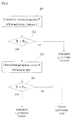
Fig. 3 is a flow chart showing an example of a displaying process performed by thedisplay apparatus 3. Since various kinds of displaying processes are provided in the displayingapparatus 3, here, it is focused on a displaying process adapted to a residual capacity of thesecondary battery 2 which is a process peculiar to the present invention. - In Step S1, the
control unit 31 checks the residual capacity R based on an information inputted from thesecondary battery 2. In the Step S2, it is determined whether the R is less than the predetermined capacity RTH or not. When the R is equal to or larger than the RTH (when determined "no" in Step S2), since the residual capacity of thebattery 2 is large enough, the ordinal luminosity control is performed. In other word, the luminosity of the backlight is set to a standard value. When R is less than RTH (when determined "yes" at Step S2), it proceeds to Step S3. - In Step S3, the
control unit 31 checks the current amount of generated electricity P based on the input from thesolar cell 1. In Step S4, it is determined whether the P is larger than the predetermined value PTH or not. When P is larger than PTH (when it is determined "yes" in Step S4), it is in a state the sun is irradiating, and thesolar cell 1 is in a power generating state. Therefore, assuming that the electricity stored in thestorage battery 2 will not vanish because thesolar cell 1 is in a power generating state even though the residual capacity of thebattery 2 is small, the ordinal luminosity control is performed. On the other hand, when the sunlight is not irradiating (for example, nighttime, cloudy, or rainy weather), P becomes smaller than PTH (in such case, it is determined "no" in Step S4). Nonetheless, if thedisplay apparatus 3 is kept on driving, the residual capacity of thesecondary battery 2 becomes zero at some time-point. Thus, the luminosity of the backlight is set lower than the standard setting in order to save the power consumption. - The embodiment of the present invention is described as above. However, the scope of the present invention is not limited thereto, and the present invention may be implemented by being subjected to various modifications without departing from the gist of the present invention.
- For example, the luminosity controlling process of the
display apparatus 3 is not restricted to the one mentioned in the above flowchart. In the daytime, the contrast degrades because of the sunlight, and the visibility of thedisplay panel 32 falls, thus the luminosity of thebacklight 39 may be set high in the daytime. On the other hand, in the nighttime, the contrast becomes large, thus luminosity of thebacklight 39 may be set low. Further, it is ideal to keep the luminosity of thebacklight 39 low at night, considering that thesolar cell 1 cannot generate electricity in nighttime. Further, the luminosity of thebacklight 39 can be controlled according to the outdoor temperature. For example, when the outdoor temperature of thedisplay apparatus 3 is high, inside of theapparatus 3 may also become high, and this may deteriorate the characteristic of the liquid crystal in thedisplay panel 32 or performance of the electronic circuits. Therefore, in order to suppress a heat generation from thebacklight 39, the luminosity of thebacklight 39 may be controlled low, when the outdoor temperature is high. Further, the luminosity of thebacklight 39 may be controlled low even though when the outside temperature is low, if the temperature inside the housing of thedisplay apparatus 3 is high. - In the above-mentioned embodiment, two sensors, i.e. the
human sensor 33 and thecamera sensor 34 are employed; however, thecamera sensor 34 may also function as a human sensor. In such case, existence of a person is detected from a captured image instead of using infrared rays done byhuman sensor 33. - In the above, an LCD panel is explained as an example of the display portion of the
display apparatus 3; however, plasma panel, organic EL (Electro-Luminescence), electronic paper, CRT, or an advertising film may be employed as the display portion instead. - In the above, the luminosity control of the
apparatus 3 is achieved by thecontrol part 31, however, this control may be performed by a dedicated control apparatus, which is separated (or independent) from theapparatus 3. - In the above, all the electricity generated in the
solar cell 1 is stored in thesecondary battery 2, however, the electric power generated by thecell 1 may be supplied directly to thedisplay apparatus 3. In such case, a control device may be arranged between thesolar cell 1, thesecondary battery 2, and thedisplay apparatus 3. This control device compares the amount of generated electricity in thesolar cell 1 and the power consumption of thedisplay apparatus 3 and if the generated amount is larger than the consumption, the surplus electric power may be charged by thesecondary battery 2. When the generated electricity is smaller than the power consumption, the electricity stored in thebattery 2 may be utilized in thedisplay apparatus 3. - In the above, the
secondary battery 2 is arranged on theroof 6 as well as thesolar cell 1. However, thebattery 2 may be arranged under theroof 6, or under thedisplay apparatus 3.
Claims (5)
- An outdoor display system comprising:a solar cell;an electricity storing unit which stores electricity obtained by the solar cell, anda display apparatus having a displaying portion displaying contents, wherein the apparatus is supplied an electric power from the storing unit or the solar cell.
- The system according to claim 1, wherein the display apparatus comprises:a display panel which displays contents;a backlight which irradiates light to the display panel, anda control unit which controls the displaying of the received contents in the display panel, wherein,the control unit performs the luminosity control of the backlight adapted to a residual capacity of the electricity storing unit.
- The system according to claim 2, wherein
the control unit controls the luminosity of the backlight based on the daylight illumination amount and the residual capacity of the secondary battery when the solar cell is not generating electricity, and
the control unit controls the luminosity of the backlight based on the daylight illumination amount only, out of the daylight illumination amount and the residual capacity of the secondary battery, when the solar cell is generating electricity. - The system according to claim 1, wherein the display apparatus comprises:a display panel which displays contents;a detecting unit which detects an existence of a person or an attribute of a person, anda control unit which controls the displaying of the received contents in the display panel, whereinthe control unit performs a display control according to the detected result in the detecting unit.
- A display apparatus, wherein the apparatus is supplied an electric power from a secondary battery or a solar cell, the apparatus comprises:a display panel which displays contents;a receiving unit which receives contents transmitted wireless;a backlight which irradiates light to the display panel;a control unit which controls the displaying of the received contents in the display panel, anda detecting unit which detects a residual capacity of a secondary battery, whereinthe control unit performs luminosity control of the backlight according to the detected result of the detecting unit.
Applications Claiming Priority (1)
| Application Number | Priority Date | Filing Date | Title |
|---|---|---|---|
| JP2010127718A JP2011253096A (en) | 2010-06-03 | 2010-06-03 | Outdoor display system and display device |
Publications (1)
| Publication Number | Publication Date |
|---|---|
| EP2393079A1 true EP2393079A1 (en) | 2011-12-07 |
Family
ID=44118062
Family Applications (1)
| Application Number | Title | Priority Date | Filing Date |
|---|---|---|---|
| EP11168226A Withdrawn EP2393079A1 (en) | 2010-06-03 | 2011-05-31 | Outdoor display system and display apparatus |
Country Status (3)
| Country | Link |
|---|---|
| US (1) | US8698732B2 (en) |
| EP (1) | EP2393079A1 (en) |
| JP (1) | JP2011253096A (en) |
Cited By (4)
| Publication number | Priority date | Publication date | Assignee | Title |
|---|---|---|---|---|
| CN103441704A (en) * | 2013-08-19 | 2013-12-11 | 苏州张扬能源科技有限公司 | Solar bus stop power supply system |
| FR3008120A1 (en) * | 2013-07-05 | 2015-01-09 | Jcdecaux Sa | STATION FOR PUBLIC TRANSPORT VEHICLES |
| EP2824386A1 (en) * | 2013-05-31 | 2015-01-14 | Coremate Technical Co., Ltd. | Bus stop supplied by renewable sources |
| EP2985908A1 (en) * | 2014-08-12 | 2016-02-17 | Aximum | Variable light display structure for highway(s) with electric power supply by photovoltaic panel(s) |
Families Citing this family (7)
| Publication number | Priority date | Publication date | Assignee | Title |
|---|---|---|---|---|
| MY170566A (en) * | 2011-12-28 | 2019-08-19 | Telekom Malaysia Berhad | A communications system |
| KR102018534B1 (en) * | 2013-04-22 | 2019-09-05 | 한국전자통신연구원 | Digital signage system and emergency alerting method using digital signage system |
| JP6504926B2 (en) * | 2015-06-03 | 2019-04-24 | 株式会社Tbグループ | Display device |
| JP6715715B2 (en) * | 2016-07-19 | 2020-07-01 | 東京電力ホールディングス株式会社 | Signage equipment |
| DE102016121154A1 (en) * | 2016-11-07 | 2018-05-09 | Two Walls Gmbh | Apparatus for reproducing information; Method for reproducing information |
| US20220398947A1 (en) * | 2021-06-07 | 2022-12-15 | Delorean, Llc | Dynamically operated sign |
| EP4414973A1 (en) * | 2023-02-10 | 2024-08-14 | Balletta Grafica S.A.S. Di Balletta Enrico | Multifunctional station |
Citations (5)
| Publication number | Priority date | Publication date | Assignee | Title |
|---|---|---|---|---|
| JP2004212443A (en) * | 2002-12-27 | 2004-07-29 | Hoyu Co Ltd | Display component and display installation |
| US20050072060A1 (en) * | 2003-09-23 | 2005-04-07 | Moncho Fernando R. | Shelter |
| US20050137754A1 (en) * | 2002-10-21 | 2005-06-23 | Bartlett Alan L. | Transportation notification, emergency response, and surveillance system |
| GB2453723A (en) * | 2007-10-15 | 2009-04-22 | Zeta Controls Ltd | Bus shelter with solar power unit |
| CN201302791Y (en) * | 2008-10-16 | 2009-09-02 | 闫华荣 | Bus stop board |
Family Cites Families (14)
| Publication number | Priority date | Publication date | Assignee | Title |
|---|---|---|---|---|
| US6532000B2 (en) * | 1997-10-01 | 2003-03-11 | Brad A. Armstrong | Analog controls housed with electronic displays for global positioning systems |
| JPH11187290A (en) * | 1997-12-22 | 1999-07-09 | Canon Inc | Image-pickup device |
| JP2001154638A (en) * | 1999-11-24 | 2001-06-08 | Casio Comput Co Ltd | Liquid crystal display device and storage medium |
| JP3873149B2 (en) * | 2002-12-11 | 2007-01-24 | 株式会社日立製作所 | Display device |
| JP2005321737A (en) * | 2004-05-11 | 2005-11-17 | Fuji Xerox Co Ltd | Image display device |
| US20070070057A1 (en) * | 2005-09-12 | 2007-03-29 | Solar Wide Industrial Ltd. | Display device and method for controlling a display device |
| US20070188483A1 (en) * | 2006-01-30 | 2007-08-16 | The Samson Group, Llc | Display apparatus for outdoor signs and related system of displays and methods of use |
| JP2008005572A (en) * | 2006-06-20 | 2008-01-10 | Sharp Corp | Photovoltaic power generation system |
| JP2009171167A (en) * | 2008-01-16 | 2009-07-30 | Olympus Imaging Corp | Camera including image display device |
| JP2009259175A (en) * | 2008-04-17 | 2009-11-05 | Mn Engineering Kk | Bus stop sign with information input/output function |
| JP5288889B2 (en) | 2008-06-03 | 2013-09-11 | 三洋電機株式会社 | Image display device |
| JP5258396B2 (en) * | 2008-06-03 | 2013-08-07 | ローム株式会社 | Liquid crystal display device control circuit and liquid crystal display system |
| JP2010093534A (en) * | 2008-10-08 | 2010-04-22 | Sharp Corp | Television broadcast-receiving apparatus |
| JP5010692B2 (en) * | 2010-01-29 | 2012-08-29 | 株式会社東芝 | Information processing apparatus and battery control method |
-
2010
- 2010-06-03 JP JP2010127718A patent/JP2011253096A/en active Pending
-
2011
- 2011-05-26 US US13/116,707 patent/US8698732B2/en active Active
- 2011-05-31 EP EP11168226A patent/EP2393079A1/en not_active Withdrawn
Patent Citations (5)
| Publication number | Priority date | Publication date | Assignee | Title |
|---|---|---|---|---|
| US20050137754A1 (en) * | 2002-10-21 | 2005-06-23 | Bartlett Alan L. | Transportation notification, emergency response, and surveillance system |
| JP2004212443A (en) * | 2002-12-27 | 2004-07-29 | Hoyu Co Ltd | Display component and display installation |
| US20050072060A1 (en) * | 2003-09-23 | 2005-04-07 | Moncho Fernando R. | Shelter |
| GB2453723A (en) * | 2007-10-15 | 2009-04-22 | Zeta Controls Ltd | Bus shelter with solar power unit |
| CN201302791Y (en) * | 2008-10-16 | 2009-09-02 | 闫华荣 | Bus stop board |
Cited By (6)
| Publication number | Priority date | Publication date | Assignee | Title |
|---|---|---|---|---|
| EP2824386A1 (en) * | 2013-05-31 | 2015-01-14 | Coremate Technical Co., Ltd. | Bus stop supplied by renewable sources |
| FR3008120A1 (en) * | 2013-07-05 | 2015-01-09 | Jcdecaux Sa | STATION FOR PUBLIC TRANSPORT VEHICLES |
| CN103441704A (en) * | 2013-08-19 | 2013-12-11 | 苏州张扬能源科技有限公司 | Solar bus stop power supply system |
| EP2985908A1 (en) * | 2014-08-12 | 2016-02-17 | Aximum | Variable light display structure for highway(s) with electric power supply by photovoltaic panel(s) |
| FR3024929A1 (en) * | 2014-08-12 | 2016-02-19 | Aximum | VARIABLE LUMINOUS DISPLAY STRUCTURE FOR ELECTRIC POWER SUPPLY (S) CIRCULATION (S) BY PHOTOVOLTAIC (X) PANEL (S). |
| US9590555B2 (en) | 2014-08-12 | 2017-03-07 | Aximum | Structure of variable light display for vehicle traffic lane(s) electrically power supplied by photovoltaic panels |
Also Published As
| Publication number | Publication date |
|---|---|
| JP2011253096A (en) | 2011-12-15 |
| US20110298697A1 (en) | 2011-12-08 |
| US8698732B2 (en) | 2014-04-15 |
Similar Documents
| Publication | Publication Date | Title |
|---|---|---|
| US8698732B2 (en) | Outdoor display system and display apparatus | |
| EP2393078A1 (en) | Outdoor display system and display apparatus | |
| JP7395715B2 (en) | solar powered display assembly | |
| US11496091B2 (en) | Electronic display assemblies with solar panels | |
| US20120139888A1 (en) | Display system | |
| RU80986U1 (en) | ELECTRONIC EXPOSURE PANELS FOR CARS | |
| JP2012016086A (en) | Outdoor display system | |
| JP3139641U (en) | Mobile panel version outdoor advertising billboard and neon sign board | |
| US20100114679A1 (en) | Programmable advertising panel powered by solar cells and communiation means thereof | |
| US20090234740A1 (en) | Advertisement display system | |
| US20100194725A1 (en) | Display Apparatus | |
| CN101572072A (en) | Image display device and power-saving control method thereof | |
| JP2013067321A (en) | Vehicle body display control device | |
| JP4134157B2 (en) | Display device | |
| JP2011257472A (en) | Outdoor display system and display device | |
| CN209880041U (en) | Multifunctional bus stop board | |
| CN102945104A (en) | Interactive light-emitting diode (LED) display screen using infrared address signals | |
| JP2009193040A (en) | Billboard of mobile panel plate and neon sign board of mobile panel plate | |
| CN210429125U (en) | Multi-functional intelligent lamp pole screen | |
| KR101340234B1 (en) | Outdoor display apparatus to be mounted on an automobile or a contruction structure | |
| CN104827979A (en) | Vehicle door/window assembly | |
| WO2012086269A1 (en) | Display device and display system | |
| WO2011138847A1 (en) | Display device, control method thereof, and image display system | |
| WO2012064681A2 (en) | Solar assisted on-vehicle electronic display system | |
| CN209843130U (en) | Advertising system for bus station |
Legal Events
| Date | Code | Title | Description |
|---|---|---|---|
| AK | Designated contracting states |
Kind code of ref document: A1 Designated state(s): AL AT BE BG CH CY CZ DE DK EE ES FI FR GB GR HR HU IE IS IT LI LT LU LV MC MK MT NL NO PL PT RO RS SE SI SK SM TR |
|
| AX | Request for extension of the european patent |
Extension state: BA ME |
|
| PUAI | Public reference made under article 153(3) epc to a published international application that has entered the european phase |
Free format text: ORIGINAL CODE: 0009012 |
|
| 17P | Request for examination filed |
Effective date: 20111129 |
|
| 17Q | First examination report despatched |
Effective date: 20120906 |
|
| GRAP | Despatch of communication of intention to grant a patent |
Free format text: ORIGINAL CODE: EPIDOSNIGR1 |
|
| INTG | Intention to grant announced |
Effective date: 20130726 |
|
| STAA | Information on the status of an ep patent application or granted ep patent |
Free format text: STATUS: THE APPLICATION IS DEEMED TO BE WITHDRAWN |
|
| 18D | Application deemed to be withdrawn |
Effective date: 20131206 |