EP2392975A2 - Wheel-organ with one-way clutch - Google Patents
Wheel-organ with one-way clutch Download PDFInfo
- Publication number
- EP2392975A2 EP2392975A2 EP11000462A EP11000462A EP2392975A2 EP 2392975 A2 EP2392975 A2 EP 2392975A2 EP 11000462 A EP11000462 A EP 11000462A EP 11000462 A EP11000462 A EP 11000462A EP 2392975 A2 EP2392975 A2 EP 2392975A2
- Authority
- EP
- European Patent Office
- Prior art keywords
- wheel
- pinion
- mobile
- teeth
- mobile according
- Prior art date
- Legal status (The legal status is an assumption and is not a legal conclusion. Google has not performed a legal analysis and makes no representation as to the accuracy of the status listed.)
- Granted
Links
- 241000282461 Canis lupus Species 0.000 claims abstract description 16
- 230000007935 neutral effect Effects 0.000 claims abstract description 4
- 238000004804 winding Methods 0.000 claims description 31
- 230000006835 compression Effects 0.000 description 3
- 238000007906 compression Methods 0.000 description 3
- 230000005540 biological transmission Effects 0.000 description 2
- 241001080024 Telles Species 0.000 description 1
- 239000000470 constituent Substances 0.000 description 1
- 238000006073 displacement reaction Methods 0.000 description 1
- 230000000694 effects Effects 0.000 description 1
- 238000004519 manufacturing process Methods 0.000 description 1
Images


Classifications
-
- G—PHYSICS
- G04—HOROLOGY
- G04B—MECHANICALLY-DRIVEN CLOCKS OR WATCHES; MECHANICAL PARTS OF CLOCKS OR WATCHES IN GENERAL; TIME PIECES USING THE POSITION OF THE SUN, MOON OR STARS
- G04B11/00—Click devices; Stop clicks; Clutches
- G04B11/006—Clutch mechanism between two rotating members with transfer of movement in only one direction (free running devices)
-
- F—MECHANICAL ENGINEERING; LIGHTING; HEATING; WEAPONS; BLASTING
- F16—ENGINEERING ELEMENTS AND UNITS; GENERAL MEASURES FOR PRODUCING AND MAINTAINING EFFECTIVE FUNCTIONING OF MACHINES OR INSTALLATIONS; THERMAL INSULATION IN GENERAL
- F16D—COUPLINGS FOR TRANSMITTING ROTATION; CLUTCHES; BRAKES
- F16D41/00—Freewheels or freewheel clutches
- F16D41/18—Freewheels or freewheel clutches with non-hinged detent
Definitions
- the present invention relates to unidirectional clutch systems designed more particularly for a watch application such as a manual and automatic winding mechanism of a timepiece.
- unidirectional clutch mobile such as those used in an automatic winding of a watch which are movable ratchet clutch, roller or vertical disengagement spring.
- Such unidirectional clutch mobiles are described for example in the publication " Theory of watchmaking "page 180, Edition of the Federation of Technical Schools (FET), Switzerland 1998 .
- these disengaging mobiles can transmit pairs of the order of 200 gr. mm which is insufficient for many applications.
- the object of the present invention is the production of a unidirectional clutch mobile which has a ratio transmitted torque / high clutch torque, whose overall height is less than 0.5 mm and can transmit a useful torque of 500 at 2000 gr. mm.
- the present invention relates to a unidirectional clutch mobile especially for a watch application and more particularly intended to be part of the gear chain of the automatic winding mechanism and / or manual of a timepiece or a watch movement that overcomes the aforementioned drawbacks.
- This unidirectional clutch mobile is distinguished by a pinion and a coaxial wheel and pivotable relative to each other, characterized in that it comprises a first drive part angularly secured to the pinion having at least one ratchet elastic having the general shape seen in plan of a C of which a branch is elongated and ends with a free end; it further comprises a second drive part angularly fixed to the wheel and coplanar with the first drive part having an internal toothing wolf tooth; and in that in the neutral position of rest the first and second drive parts do not touch each other, the end of the resilient pawls in the non-elastically deformed rest position being located on a circumference whose diameter is larger than a circumference passing through the apex of the wolf teeth and smaller than a circumference passing through the bottom of the teeth of the toothing of the second driving piece.
- the present invention also relates to a winding mechanism of a timepiece comprising such a unidirectional clutch mobile and a timepiece comprising one or more of these unidirectional clutch mobile.
- the unidirectional clutch mobile is primarily intended to equip a watch movement, including its winding mechanism, and not the clothing of a watch.
- this mobile unidirectional clutch must allow a very small footprint, less than 0.5 mm, typically a thickness of 0.3 mm. It must also be able to transmit, in a direction of rotation, a significant torque up to 1000 gr. mm see more without any damage. It must finally have a resisting torque in the opposite direction of rotation as small as possible, typically of the order of 3 to 10 gr. mm.
- Such a clutch mobile must therefore have a ratio between its maximum transmission torque and its very high minimum resistance torque of the order of 1/200 to 1/400.
- Another object of the present invention is to provide a unidirectional clutch mobile to reduce the wear of its constituent parts.
- the present unidirectional clutch mobile does not seek to reduce a blind spot, especially in an automatic winding mechanism. It is also not a function of limiting a transmission torque, it is sought to have in one direction a maximum transmitted torque and in the other direction of rotation a minimum resistive torque.
- the unidirectional disengaged mobile illustrated has a pinion 1 secured to an axis 2.
- pinion 1 has come from a workpiece with this axis 2.
- This axis 2 comprises, adjacent an end face of the pinion 1, a first reach 3 followed by a second span 4 of larger diameter, itself followed by a third range 5 of diameter greater than that of the second median reach 4.
- This unidirectional clutch mobile further comprises a wheel 6 whose periphery has a toothing 7.
- This wheel 6 is idle rotated on the second bearing 4 of the axis 2 and its axial position relative to this axis 2 is provided by a part by the free front face of the first bearing 3 of the axis 2 and secondly by a washer 8 driven on the third bearing 5 of the axis 2.
- This washer 8 is housed at least partially in a circular recess 9 that presents the free front face 10 of the wheel 6 to reduce the overall height of the mobile.
- the wheel 6 comprises a hub 11 whose opposite face to the recess 9 is provided with a recess 12.
- This recess 12 is of generally cylindrical shape and comprises recesses 13 made in its lateral face.
- the mobile therefore comprises a pinion 1 secured to its axis 2 and a wheel 6 pivoted freely over a median distance 4 of this axis and held axially on this axis by a washer 8 driven on a third bearing surface 5 of said axis 2.
- first drive member 14 angularly integral with the axis 2 and having elastic pawls 15 cooperating with an asymmetric toothing of wolf teeth 16 carried by the inner edge of a second piece annular drive 17 angularly integral with the wheel 6.
- the first drive part 14 has a central opening through which the first bearing 3 of the axis 2 passes.
- This first bearing 3 can have a non-circular shape, corresponding to the shape of the central opening of the first drive part 14, so that the first drive part is angularly secured to the axis 2.
- this first drive part 14 could be driven, welded or glued on the first bearing 3 of the axis 2.
- This first workpiece comprises in the example shown five elastic catches 15 connected by their thick base to the central portion of the first drive part 14 and extending outwardly while tapering to form ratchets 15 elastically deformable radially.
- the second drive part 17 is annular and has on its inner wall an asymmetrical toothing 16 in the shape of a wolf tooth.
- the outer edge of this second annular drive part has bosses 18.
- This second annular drive part 17 is disposed in the recess 12 of the hub 11 of the wheel 6, the bosses 18 are housed in the housing 13 of the hub 11 to angularly secure the wheel 6 of the second workpiece 17.
- the ends of the elastic pawls 15 are disposed on a circumference of a diameter a, the pawls being at rest not elastically deformed and out of contact with the second driving part 17.
- the top of the teeth 16 of the second driving part 17 are situated on a diameter smaller than the diameter of the circumference a and the recesses of this toothing 16 are located on a circumference of a larger diameter than the circumference forming the casing of the first drive part 14 when it is in the state of rest not elastically deformed.
- the driving parts 14 and 17 do not touch each other and the wheel 6 is free to move angularly relative to the pinion 1 without effort.
- the unidirectional clutch mobile allows easy and easy mounting of the driving parts 14, 17 in one another and reduces the load torque when the wheel 6 is driven in the opposite direction.
- the pawls 15 only touching the teeth 16 on an angular extent of 60 ° to 180 ° is for about 1/2 to 1/6 of a full revolution of the wheel 6 relative to the pinion 1 .
- the elastic catches 15 rub against the teeth 16 only at an angle of 8, 5 ° in steps of 24 ° of rotation of the wheel 6 in the clockwise direction relative to the pinion 1. The friction and wear of these drive parts are reduced accordingly.
- the figure 6 shows a relative position of the wheel 6 with respect to the pinion 1 for which the end of the elastic pawls 15 is in contact with the top of a tooth 16.
- the resilient pawls 15 are elastically deformed, their ends coming into contact with each other. position on a circumference of diameter smaller than the circumference a to be able, during an additional rotation of the wheel 6 relative to the pinion 1 in the clockwise direction to escape the teeth 16.
- the radial displacement towards the inside of the pawls is low and causes only little effort so as to reduce as much as possible the resistant torque and the wear of the driving parts when the wheel 6 rotates. in a clockwise direction relative to the pinion 1 corresponding to the disengagement of the clutch mobile.
- the maximum torque-to-torque ratio is 1/200.
- the outer diameter of the hub 11 of the wheel 6 is 3.2 mm and the height H of this hub of 0.32 mm, the bulk due to the unidirectional clutch system is really very small despite the high value of the torque that can be transmitted, since it requires a thickness of the order of 0.15 to 0.25 mm only to accommodate the two drive parts 14, 17.
- the toothed wheel 6 is integral with a tubular hub 20, or has come from a workpiece with this tubular hub.
- the board of this wheel 6 has an annular recess 21 for receiving the driving parts 14, 17.
- the pinion 1 comprises an annular skirt 22 and is pivoted freely on the hub 20 of the wheel 6.
- the first drive part 14 which is angularly secured to the pinion 1 and the second drive part 17 which is angularly attached to the wheel 6.
- the mounting of this clutch mobile on a barrel bridge 24 is seen with a fixing screw 23.
- the hub 20 of the wheel 6 is idler pivoted on a tubular central portion 25 of the barrel bridge 24 in the recess of which is screwed the fixing screw 23.
- the first driving part 14 comprises four elastic pawls 15 and the second driving part 17 comprises eight wolf teeth 16.
- this second embodiment is the same as that of the first embodiment with the only difference that the angular amplitude of a step is 45 ° and that for each step the elastic catches 15 are not contact with the second drive part 17 only over an angular extent of 11 °.
- the maximum breaking torque of this embodiment is greater than 1400 gr. mm and the minimum resistance torque of 7 gr. mm which gives a ratio of more than 1/200.
- the unidirectional clutch mobile has exactly the same size as a corresponding non-disengageable mobile since the clutch system, the two parts 14, 17 are housed in the recess 21 formed in the plate of the wheel 6.
- the disengaged mobile described is more particularly intended to equip or be used in applications and mechanism part of watch movements.
- the figure 10 illustrates a particular application of movable clutch according to the invention in a self-winding watch movement.
- the barrel ratchet 30 mounted on the axis 31 of a barrel 32 is engaged on the one hand with an automatic intermediate ratchet 33 and on the other hand with an intermediate ratchet 34.
- the intermediate ratchet winding 34 is constituted by a clutch mobile according to the second embodiment described above.
- the hub 22 of the wheel 6 is pivoted on an axis 35 and this wheel 6 is engaged with the ratchet 30.
- the pinion 1 of this clutch mobile is engaged with a crown wheel 36 driven by a winding pinion 37 angularly secured to the winding stem 38 of the clockwork movement.
- the intermediate ratchet winding 34 disengages and does not drive the crown wheel 36.
- the automatic intermediate ratchet 33 is engaged with the pinion of a ratchet-driving wheel 39 whose wheel meshes with the pinion of a reduction wheel 40 whose wheel is in engagement with the pinion of a wheel. arming 41 cooperating with a spring latch 42 and driven by an automatic winding mass (not shown).
- the ratchet driving wheel 39 is formed of a disengaging wheel according to the first embodiment described above.
- the pinion 1 of this clutch mobile is engaged with the automatic intermediate ratchet 33 and the wheel 6 of this clutch mobile is engaged with the pinion of the reduction wheel 40.
- Such a mechanism for winding an automatic watch movement comprising a disengaging wheel between the crown wheel and the barrel ratchet and a second disengaging wheel in the kinematic connection between the barrel ratchet and the winding wheel enables significantly reduce the wear of the winding mechanism and improve its winding speed.
Landscapes
- Engineering & Computer Science (AREA)
- General Engineering & Computer Science (AREA)
- Physics & Mathematics (AREA)
- General Physics & Mathematics (AREA)
- Mechanical Engineering (AREA)
- Mechanical Operated Clutches (AREA)
- Gear Transmission (AREA)
Abstract
Description
La présente invention se rapporte aux systèmes d'embrayage unidirectionnels conçus plus particulièrement pour une application horlogère tel qu'un mécanisme de remontage manuel et automatique d'une pièce d'horlogerie.The present invention relates to unidirectional clutch systems designed more particularly for a watch application such as a manual and automatic winding mechanism of a timepiece.
Il existe différents types de mobile d'embrayage unidirectionnel tels ceux utilisés dans un rouage de remontage automatique d'une montre qui sont des mobiles d'embrayage à cliquets, à galets ou à ressort débrayeur verticaux. De tels mobiles d'embrayage unidirectionnels sont décrit par exemple dans la publication "
L'inconvénient majeur de tels mobiles d'embrayage est leur encombrement en hauteur qui est d'au moins 0,7 mm, plus généralement supérieur à 1 mm.The major disadvantage of such clutch mobiles is their overall height which is at least 0.7 mm, more generally greater than 1 mm.
De plus ces mobiles de débrayage permettent de transmettre des couples de l'ordre de 200 gr. mm ce qui est insuffisant pour de nombreuses applications.In addition, these disengaging mobiles can transmit pairs of the order of 200 gr. mm which is insufficient for many applications.
On connaît encore du document
Le but de la présente invention est la réalisation d'un mobile d'embrayage unidirectionnel qui présente un rapport couple transmis/couple de débrayage élevé, dont l'encombrement en hauteur soit inférieur à 0,5 mm et pouvant transmettre un couple utile de 500 à 2000 gr. mm.The object of the present invention is the production of a unidirectional clutch mobile which has a ratio transmitted torque / high clutch torque, whose overall height is less than 0.5 mm and can transmit a useful torque of 500 at 2000 gr. mm.
La présente invention a pour objet un mobile d'embrayage unidirectionnel notamment pour une application horlogère et plus particulièrement destiné à faire partie de la chaîne d'engrenages du mécanisme de remontage automatique et/ou manuel d'une pièce d'horlogerie ou d'un mouvement d'horlogerie qui obvie aux inconvénients précités.The present invention relates to a unidirectional clutch mobile especially for a watch application and more particularly intended to be part of the gear chain of the automatic winding mechanism and / or manual of a timepiece or a watch movement that overcomes the aforementioned drawbacks.
Ce mobile d'embrayage unidirectionnel se distingue par un pignon et une roue coaxiaux et pivotant l'un par rapport à l'autre, caractérisé par le fait qu'il comporte une première pièce d'entraînement solidaire angulairement du pignon comportant au moins un cliquet élastique présentant la forme générale vu en plan d'un C dont une branche est allongée et se termine par une extrémité libre; qu'il comporte encore une seconde pièce d'entraînement solidaire angulairement de la roue et coplanaire avec la première pièce d'entraînement comportant une denture interne en dent de loup; et par le fait qu'en position neutre de repos les première et seconde pièces d'entraînement ne se touchent pas, l'extrémité des cliquets élastiques en position de repos non déformés élastiquement étant situés sur une circonférence dont le diamètre est plus grand qu'une circonférence passant par le sommet des dents de loup et plus petit qu'une circonférence passant pas le fond des dents de la denture de la seconde pièce d'entraînement.This unidirectional clutch mobile is distinguished by a pinion and a coaxial wheel and pivotable relative to each other, characterized in that it comprises a first drive part angularly secured to the pinion having at least one ratchet elastic having the general shape seen in plan of a C of which a branch is elongated and ends with a free end; it further comprises a second drive part angularly fixed to the wheel and coplanar with the first drive part having an internal toothing wolf tooth; and in that in the neutral position of rest the first and second drive parts do not touch each other, the end of the resilient pawls in the non-elastically deformed rest position being located on a circumference whose diameter is larger than a circumference passing through the apex of the wolf teeth and smaller than a circumference passing through the bottom of the teeth of the toothing of the second driving piece.
La présente invention a également pour objet un mécanisme de remontage d'une pièce d'horlogerie comportant un tel mobile d'embrayage unidirectionnel ainsi qu'une pièce d'horlogerie comprenant un ou plusieurs de ces mobiles d'embrayage unidirectionnels.The present invention also relates to a winding mechanism of a timepiece comprising such a unidirectional clutch mobile and a timepiece comprising one or more of these unidirectional clutch mobile.
Le dessin annexé illustre schématiquement et à titre d'exemple une forme d'exécution du mobile d'embrayage unidirectionnel ainsi qu'un mécanisme de remontage d'une pièce d'horlogerie muni de tels mobiles d'embrayage unidirectionnels.
- La
figure 1 est une vue en perspective de dessous du mobile d'embrayage unidirectionnel. - La
figure 2 est une vue en perspective de dessus. - La
figure 3 est une vue en coupe diamétrale du mobile d'embrayage unidirectionnel. - Les
figures 4 ,5 et6 sont des vues en plan de dessus du mobile d'embrayage unidirectionnel dans trois positions différentes. - La
figure 7 est une vue en coupe d'une seconde forme d'exécution du mobile d'embrayage et son montage sur un pont à l'aide d'une vis. - La
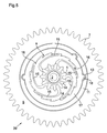
figure 8 illustre en plan la seconde forme d'exécution du mobile d'embrayage seul. - La
figure 9 est une vue en coupe suivant la ligne A-A de lafigure 7 , le pont et la vis de fixation du mobile d'embrayage étant enlevés. - La
figure 10 illustre schématiquement en perspective le mécanisme de remontage manuel et automatique d'un mouvement d'horlogerie comprenant deux mobiles d'embrayage unidirectionnels selon l'invention.
- The
figure 1 is a perspective view from below of the unidirectional clutch mobile. - The
figure 2 is a perspective view from above. - The
figure 3 is a diametrical sectional view of the unidirectional clutch mobile. - The
figures 4 ,5 and6 are top plan views of the unidirectional clutch mobile in three different positions. - The
figure 7 is a sectional view of a second embodiment of the clutch mobile and mounting on a bridge with a screw. - The
figure 8 illustrates in plan the second embodiment of the clutch mobile alone. - The
figure 9 is a sectional view along line AA of thefigure 7 , the bridge and the fixing screw of the clutch mobile being removed. - The
figure 10 schematically illustrates in perspective the manual and automatic winding mechanism of a watch movement comprising two unidirectional clutch mobiles according to the invention.
Le mobile d'embrayage unidirectionnel selon l'invention est principalement destiné à équiper un mouvement de montre, notamment son mécanisme de remontage, et non pas l'habillement d'une pièce horlogère. En fait, ce mobile d'embrayage unidirectionnel doit permettre un encombrement en hauteur très faible, inférieure à 0,5 mm, typiquement d'une épaisseur de 0,3 mm. Il doit de plus être capable de transmettre, dans un sens de rotation, un couple important pouvant aller jusqu'à 1000 gr. mm voir plus sans subir de dommage. Il doit enfin présenter un couple résistant dans le sens de rotation inverse aussi faible que possible typiquement de l'ordre de 3 à 10 gr. mm. Un tel mobile d'embrayage doit donc présenter un rapport entre son couple maximum de transmission et son couple résistant minimum très élevé de l'ordre de 1/200 à 1/400.The unidirectional clutch mobile according to the invention is primarily intended to equip a watch movement, including its winding mechanism, and not the clothing of a watch. In fact, this mobile unidirectional clutch must allow a very small footprint, less than 0.5 mm, typically a thickness of 0.3 mm. It must also be able to transmit, in a direction of rotation, a significant torque up to 1000 gr. mm see more without any damage. It must finally have a resisting torque in the opposite direction of rotation as small as possible, typically of the order of 3 to 10 gr. mm. Such a clutch mobile must therefore have a ratio between its maximum transmission torque and its very high minimum resistance torque of the order of 1/200 to 1/400.
Un autre but de la présente invention est de réaliser un mobile d'embrayage unidirectionnel permettant de réduire l'usure de ses pièces constitutives.Another object of the present invention is to provide a unidirectional clutch mobile to reduce the wear of its constituent parts.
Par contre le présent mobile d'embrayage unidirectionnel ne cherche pas à diminuer un angle mort, notamment dans un mécanisme de remontage automatique. Il n'a pas non plus comme fonction de limiter un couple de transmission, on cherche à avoir dans un sens un couple transmis maximal et dans l'autre sens de rotation un couple résistant minimal.On the other hand, the present unidirectional clutch mobile does not seek to reduce a blind spot, especially in an automatic winding mechanism. It is also not a function of limiting a transmission torque, it is sought to have in one direction a maximum transmitted torque and in the other direction of rotation a minimum resistive torque.
Ceci étant préalablement posé une première forme d'exécution du mobile de débrayage unidirectionnel selon l'invention va être décrit dans ce qui suit en référence aux
Le mobile de débrayage unidirectionnel illustré comporte un pignon 1 solidaire d'un axe 2. Généralement ce pignon 1 est venu d'une pièce de fabrication avec cet axe 2. Cet axe 2 comporte, jouxtant une face terminale du pignon 1, une première portée 3 suivie d'une seconde portée 4 de plus grand diamètre, elle-même suivie d'une troisième portée 5 de diamètre supérieur à celui de la seconde portée médiane 4.The unidirectional disengaged mobile illustrated has a
Ce mobile d'embrayage unidirectionnel comporte encore une roue 6 dont la périphérie présente une denture 7. Cette roue 6 est pivotée folle sur la seconde portée 4 de l'axe 2 et sa position axiale par rapport à cet axe 2 est assurée d'une part par la face frontale libre de la première portée 3 de l'axe 2 et d'autre part par une rondelle 8 chassée sur la troisième portée 5 de l'axe 2. Cette rondelle 8 est logée au moins partiellement dans une creusure circulaire 9 que présente la face frontale libre 10 de la roue 6 pour réduire l'encombrement en hauteur du mobile.This unidirectional clutch mobile further comprises a
La roue 6 comporte un moyeu 11 dont la face opposée à la creusure 9 est munie d'un évidement 12. Cet évidement 12 est de forme générale cylindrique et comporte des logements 13 pratiqués dans sa face latérale.The
Le mobile comporte donc un pignon 1 solidaire de son axe 2 et une roue 6 pivotée librement sur une portée médiane 4 de cet axe et maintenue axialement sur cet axe par une rondelle 8 chassée sur une troisième portée 5 dudit axe 2.The mobile therefore comprises a
La fonction de débrayage unidirectionnel du mobile est réalisée par une première pièce d'entraînement 14 solidaire angulairement de l'axe 2 et comportant des cliquets élastiques 15 coopérant avec une denture asymétrique en dents de loup 16 portée par la tranche interne d'une seconde pièce d'entraînement annulaire 17 solidaire angulairement avec la roue 6.The function of unidirectional disengagement of the mobile is carried out by a
La première pièce d'entraînement 14 présente une ouverture centrale traversée par la première portée 3 de l'axe 2. Cette première portée 3 peut présenter une forme non circulaire, correspondant à la forme de l'ouverture centrale de la première pièce d'entraînement 14, de manière à ce que cette première pièce d'entraînement soit angulairement solidaire de l'axe 2.The
Dans des variantes cette première pièce d'entraînement 14 pourrait être chassée, soudée ou collée sur la première portée 3 de l'axe 2.In variants this
Cette première pièce d'entraînement comporte dans l'exemple illustré cinq cliquets élastiques 15 reliés par leur base épaisse à la partie centrale de la première pièce d'entraînement 14 et s'étendant vers l'extérieur tout en s'amincissant pour former des cliquets 15 élastiquement déformable radialement.This first workpiece comprises in the example shown five
La seconde pièce d'entraînement 17 est annulaire et comporte sur sa paroi interne une denture asymétrique 16 en forme de dent de loup. La tranche extérieure de cette seconde pièce d'entraînement annulaire comporte des bossages 18.The
Cette seconde pièce d'entraînement annulaire 17 est disposée dans l'évidement 12 du moyeu 11 de la roue 6, les bossages 18 viennent se loger dans les logements 13 de ce moyeu 11 pour solidariser angulairement la roue 6 de cette seconde pièce d'entraînement 17.This second
Ainsi les deux pièces d'entraînements 14 et 17 sont disposées dans l'évidement 12 du moyeu 11 de la roue 6 et sont coplanaires.Thus the two parts of
A l'état de repos du mobile d'embrayage unidirectionnel illustré à la
Typiquement dans l'exemple illustré où la première pièce d'entraînement 14 comporte cinq cliquets élastiques 15 et ou la seconde pièce d'entraînement 17 comporte quinze dents 16, les cliquets 15 élastiques ne frottent contre les dents 16 que sur un angle de 8,5° par pas de 24° de rotation de la roue 6 dans le sens horaire par rapport au pignon 1. Le frottement et l'usure de ces pièces d'entraînement sont donc réduits d'autant.Typically in the illustrated example where the first driving
La
Comme on le voit au dessin, le déplacement radial vers l'intérieur des cliquets est faible et n'entraîne que peu d'effort de manière à réduire au maximum le couple résistant et l'usure des pièces d'entraînement lorsque la roue 6 tourne en sens horaire par rapport au pignon 1 correspondant au débrayage du mobile d'embrayage.As can be seen in the drawing, the radial displacement towards the inside of the pawls is low and causes only little effort so as to reduce as much as possible the resistant torque and the wear of the driving parts when the
Par contre une rotation dans le sens anti-horaire de la roue 6 par rapport au pignon 1 à partir de l'état de repos illustré à la
Les essais ont montré que pour un mobile d'embrayage à cinq cliquets élastiques 15 et quinze dents 16 le couple résistant, lors de la rotation dans le sens du débrayage, entre la roue 6 et le pignon 1 est de l'ordre de 5 gr. mm. tandis que le couple maximum ou de rupture des cliquets élastiques 15 lors de la rotation dans le sens de l'embrayage entre la roue 6 et le pignon 1 est de l'ordre de 1800 gr. mm. On a donc un rapport de couple maximum sur un couple résistant de l'ordre de 1/360. Suivant les formes d'exécution du mobile d'embrayage et notamment du nombre de cliquets élastiques 15 et de dents 16, ce rapport du couple maximum au couple résistant peut varier entre 1/200 et 1/500.The tests have shown that for a clutch mobile with five
Par exemple dans une exécution de mobile d'embrayage comportant quatre cliquets élastiques 15 et huit dents 16, le rapport couple maximum sur couple résistant est de 1/200.For example, in a clutch mobile embodiment comprising four
Dans la forme d'exécution illustrée comportant cinq cliquets élastiques 15 et quinze dents 16 le diamètre extérieur du moyeu 11 de la roue 6 est de 3,2 mm et la hauteur H de ce moyeu de 0,32 mm, l'encombrement dû au système d'embrayage unidirectionnel est donc réellement très réduit malgré la valeur élevée du couple pouvant être transmis, puisqu'il nécessite une épaisseur de l'ordre de 0,15 à 0,25 mm seulement pour loger les deux pièces d'entraînement 14,17.In the illustrated embodiment comprising five
Une seconde forme d'exécution du mobile d'embrayage unidirectionnel va être décrit dans ce qui suit en référence aux
Dans cette seconde forme d'exécution la roue dentée 6 est solidaire d'un moyeu tubulaire 20, ou est venue d'une pièce de fabrication avec ce moyeu tubulaire.In this second embodiment, the
La planche de cette roue 6 comporte un évidement annulaire 21 destiné à recevoir les pièces d'entraînement 14, 17.The board of this
Le pignon 1 comporte une jupe annulaire 22 et est pivoté librement sur le moyeu 20 de la roue 6.The
Dans l'évidement 21 de la roue 6 sont disposées, comme dans l'évidement 12 de la première forme d'exécution, la première pièce d'entraînement 14 qui est solidaire angulairement du pignon 1 et la seconde pièce d'entraînement 17 qui est solidaire angulairement de la roue 6. Sur la
Dans cette seconde forme d'exécution la première pièce d'entraînement 14 comporte quatre cliquets élastiques 15 et la seconde pièce d'entraînement 17 comporte huit dents de loup 16.In this second embodiment the first driving
Le fonctionnement de cette seconde forme d'exécution est le même que celui de la première forme d'exécution à la seule différence que l'amplitude angulaire d'un pas est de 45° et que pour chaque pas les cliquets élastiques 15 ne sont en contact avec la seconde pièce d'entraînement 17 que sur une étendue angulaire de 11°.The operation of this second embodiment is the same as that of the first embodiment with the only difference that the angular amplitude of a step is 45 ° and that for each step the
Le couple maximum de rupture de cette forme d'exécution est supérieur à 1400 gr. mm et le couple minimum de résistance de 7 gr. mm ce qui donne un rapport de plus de 1/200.The maximum breaking torque of this embodiment is greater than 1400 gr. mm and the minimum resistance torque of 7 gr. mm which gives a ratio of more than 1/200.
Dans cette forme d'exécution le mobile d'embrayage unidirectionnel présente exactement le même encombrement qu'un mobile non débrayable correspondant puisque le système d'embrayage, soit les deux pièces d'entraînement 14, 17 sont logées dans l'évidement 21 pratiqué dans la planche de la roue 6.In this embodiment the unidirectional clutch mobile has exactly the same size as a corresponding non-disengageable mobile since the clutch system, the two
Comme on peut s'en rendre compte immédiatement si l'on doit inverser le sens d'entraînement du pignon par la roue il suffit de retourner les deux pièces d'entraînement 14, 17.As can be seen immediately if one must reverse the drive direction of the pinion by the wheel just return the two
Dans toutes les formes d'exécution possible de ce mobile d'embrayage unidirectionnel on bénéficie des avantages suivants :
- 1. Très faible encombrement en hauteur car le dispositif d'embrayage est logé dans un évidement pratiqué dans la planche du mobile.
- 2. Un montage très facile car il suffit de placer les première et seconde pièces d'entraînement 14, 17 dans l'évidement de la roue. Ceci s'effectuera très facilement lorsque la position angulaire de la roue et du pignon est telle que le mobile d'embrayage est dans son état de repos, neutre, pour lequel les cliquets élastiques ne sont pas en contact avec la seconde pièce d'entraînement.
- 3. Le couple minimum résistant lorsque le mobile tourne dans le sens du débrayage est très faible parce que les cliquets élastiques ne sont en contact avec la seconde pièce d'entraînement que
pendant 1/2ou 1/6 d'un tour complet du pignon par rapport à la roue. De plus la forme en C avec une branche externe fine et allongée des cliquets élastiques fait que lorsqu'ils doivent s'escamoter radialement pour le passage des dents une très faible force est suffisante. De plus, ce couple n'est pas constant et ne s'exerce que pendant que les cliquets élastiques sont en contact avec la seconde pièce d'entraînement. - 4. Les cliquets élastiques n'étant pas continuellement en contact avec la seconde pièce d'entraînement, l'usure des cliquets élastiques et des dents de loup de la seconde pièce d'entraînement est fortement réduite.
- 5. Toujours grâce à la forme des cliquets élastiques le couple transmis lorsque le mobile fonctionne en embrayage est élevé car les cliquets travaillent en compression et leur base coudée les reliant à la première pièce d'entraînement est épaisse et très résistante.
- 1. Very small size in height because the clutch device is housed in a recess formed in the mobile board.
- 2. A very easy assembly because it is sufficient to place the first and
second drive parts - 3. The minimum resistance torque when the wheel rotates in the disengagement direction is very low because the spring catches are in contact with the second driving part only for 1/2 or 1/6 of a full turn of the pinion relative to the wheel. In addition, the C shape with a thin and elongated outer branch of the elastic pawls means that when they have to retract radially for the passage of the teeth, a very weak force is sufficient. Moreover, this couple is not constant and only while the resilient pawls are in contact with the second drive part.
- 4. Since the resilient pawls are not continuously in contact with the second driving part, the wear of the elastic pawls and wolf teeth of the second driving part is greatly reduced.
- 5. Still thanks to the shape of the elastic pawls the torque transmitted when the mobile operates in clutch is high because the pawls work in compression and their bent base connecting them to the first drive part is thick and very strong.
Les caractéristiques importantes du mobile d'embrayage unidirectionnel selon l'invention sont :
- a) La forme en C avec une branche extérieure allongée et effilée des cliquets élastiques pour leur permettre d'être déformés élastiquement radialement sous l'effet d'une faible force. La base reliant ces cliquets élastiques à la première pièce d'entraînement étant épaisse et résistante permet de transmettre un couple important.
- b) Le fait que pour une révolution complète du pignon par rapport à la roue, dans le sens du débrayage, les cliquets élastiques sont en contact avec la denture en dent de loup au plus pendant 180° réduira ainsi l'usure des pièces et le couple résistant.
- c) Que les première et seconde pièces d'entraînement 14, 17 sont logées dans un évidement pratiqué dans la planche de la roue ce qui réduit grandement l'encombrement en hauteur du mobile d'embrayage unidirectionnel.
- d) L'extrémité des cliquets élastiques à l'état de repos, lorsqu'ils ne sont pas en contact avec la denture de la seconde pièce d'entraînement, est située sur une circonférence de diamètre plus grand que la circonférence passant par le sommet des dents 16 de la seconde pièce d'entraînement et plus petit que la circonférence passant par les fonds de ladite denture.
- e) Le rapport du couple résistant, lorsque le mobile débraye, par rapport au couple maximum de rupture, lorsque le mobile embraye, est compris entre 1/200
et 1/800.
Le couple résistant est inférieur à 20 gr. mm de préférence de 5 à 15 gr. mm.
Le couple de rupture est supérieur à 1000 gr. mm de préférence entre 1300 gr. mm et 1800 gr. mm. - f) Le nombre de cliquets élastiques est par exemple compris
entre 1 et 12, de préférence entre 3et 8 et le nombre de dents de loup est par exemple comprisentre 3 et 60.
- a) The C shape with an elongated and tapering outer branch of the elastic pawls to allow them to be deformed elastically radially under the effect of a weak force. The base connecting these resilient pawls to the first drive part being thick and strong makes it possible to transmit a large torque.
- b) The fact that for a complete revolution of the pinion with respect to the wheel, in the direction of the clutch, the elastic pawls are in contact with the teeth in wolf teeth at most during 180 ° will thus reduce the wear of the parts and the resistant torque.
- c) That the first and
second drive parts - d) The end of the resilient pawls at rest, when not in contact with the toothing of the second driving part, is located on a circumference of diameter greater than the circumference passing through the
top teeth 16 of the second driving part and smaller than the circumference passing through the bottoms of said toothing. - e) The ratio of the resistant torque, when the mobile disengages, with respect to the maximum breaking torque, when the mobile gear, is between 1/200 and 1/800.
The resistant torque is less than 20 gr. mm, preferably from 5 to 15 gr. mm.
The breaking torque is greater than 1000 gr. mm preferably between 1300 gr. mm and 1800 gr. mm. - f) The number of elastic pawls is for example between 1 and 12, preferably between 3 and 8 and the number of wolf teeth is for example between 3 and 60.
Le mobile de débrayage décrit est plus particulièrement destiné à équiper ou être utilisé dans des applications et mécanisme faisant partie de mouvements horlogers. A titre d'exemple, la
Dans cet exemple, le rochet de barillet 30 monté sur l'axe 31 d'un barillet 32 est en prise d'une part avec un rochet intermédiaire d'automatique 33 et d'autre part avec un rochet intermédiaire de remontoir 34.In this example, the barrel ratchet 30 mounted on the
Le rochet intermédiaire de remontoir 34 est ici constitué par un mobile d'embrayage selon la seconde forme d'exécution décrite plus haut. Le moyeu 22 de la roue 6 est pivoté sur un axe 35 et cette roue 6 est en prise avec le rochet 30. Le pignon 1 de ce mobile d'embrayage est en prise avec une roue de couronne 36 entraînée par un pignon de remontoir 37 solidaire angulairement de la tige de remontoir 38 du mouvement d'horlogerie.The intermediate ratchet winding 34 is constituted by a clutch mobile according to the second embodiment described above. The
Ainsi lorsque l'usager tourne la couronne de remontoir de sa montre dans le sens horaire il entraîne par l'intermédiaire de la roue de couronne 36 le pignon 1 et la roue 6 du rochet intermédiaire 34 de remontoir dans le sens horaire et finalement le rochet 30 du barillet dans le sens anti-horaire.Thus when the user turns the winding crown of his watch clockwise it drives through the
Par contre lorsque le rochet de barillet 30 est entraîné, comme on le verra plus loin, par la roue de remontage automatique, le rochet intermédiaire du remontoir 34 débraye et n'entraîne pas la roue de couronne 36.By against when the barrel ratchet 30 is driven, as will be seen later, by the automatic winding wheel, the intermediate ratchet winding 34 disengages and does not drive the
Le rochet intermédiaire d'automatique 33 est en prise avec le pignon d'un mobile entraîneur de rochet 39 dont la roue engrène avec le pignon d'un mobile de réduction 40 dont la roue est en prise avec le pignon d'une roue d'armage 41 coopérant avec un cliquet d'arrêt à ressort 42 et entraînée par une masse de remontage automatique (non illustrée).The automatic
Dans cette liaison cinématique de remontage automatique, la roue entraîneuse de rochet 39 est formée d'un mobile de débrayage selon la première forme d'exécution décrite plus haut. Le pignon 1 de ce mobile d'embrayage est en prise avec le rochet intermédiaire d'automatique 33 et la roue 6 de ce mobile d'embrayage est en prise avec le pignon de la roue de réduction 40.In this kinematic automatic winding connection, the
Lorsque la roue d'armage 41 est entraînée par la masse de remontage automatique dans le sens anti-horaire la roue 1 du mobile d'embrayage formant la roue entraîneuse de rochet 39 tourne dans le sens anti-horaire entraînant également le pignon 1 de ce mobile dans le sens anti-horaire et donc le rochet de barillet 30 également dans le sens anti-horaire par l'intermédiaire du rochet intermédiaire d'automatique 33.When the winding
Par contre lorsque le rochet intermédiaire d'automatique 33 est entraîné par le rochet de barillet lors du remontage manuel, le pignon 1 du mobile d'embrayage 39 est entraîné dans le sens horaire et la roue 6 de ce mobile d'embrayage n'est pas entraînée.On the other hand, when the automatic
Ainsi grâce à l'utilisation de deux mobiles d'embrayage 34, 39 on évite lors du remontage manuel l'entraînement de la roue de réduction 40 et de la roue d'armage 41 ménageant ainsi l'usure de sa denture et de son cliquet 42. Lors du remontage automatique du barillet 32 le mobile d'embrayage 34 débraye et la roue de couronne n'est pas entraînée.Thus, thanks to the use of two
Un tel mécanisme de remontage d'un mouvement de montre automatique comportant un mobile de débrayage entre la roue de couronne et le rochet de barillet et un second mobile de débrayage dans la liaison cinématique entre le rochet de barillet et la roue d'armage permet de réduire de façon importante l'usure du mécanisme de remontage et d'améliorer sa vitesse de remontage.Such a mechanism for winding an automatic watch movement comprising a disengaging wheel between the crown wheel and the barrel ratchet and a second disengaging wheel in the kinematic connection between the barrel ratchet and the winding wheel enables significantly reduce the wear of the winding mechanism and improve its winding speed.
Claims (10)
Applications Claiming Priority (1)
| Application Number | Priority Date | Filing Date | Title |
|---|---|---|---|
| CH00887/10A CH702924B1 (en) | 2010-06-03 | 2010-06-03 | Mobile-way clutch, winding mechanism and a timepiece including said mobile. |
Publications (3)
| Publication Number | Publication Date |
|---|---|
| EP2392975A2 true EP2392975A2 (en) | 2011-12-07 |
| EP2392975A3 EP2392975A3 (en) | 2018-01-24 |
| EP2392975B1 EP2392975B1 (en) | 2019-05-15 |
Family
ID=44774315
Family Applications (1)
| Application Number | Title | Priority Date | Filing Date |
|---|---|---|---|
| EP11000462.9A Active EP2392975B1 (en) | 2010-06-03 | 2011-01-21 | Wheel-organ with one-way clutch |
Country Status (3)
| Country | Link |
|---|---|
| US (1) | US8337077B2 (en) |
| EP (1) | EP2392975B1 (en) |
| CH (1) | CH702924B1 (en) |
Cited By (9)
| Publication number | Priority date | Publication date | Assignee | Title |
|---|---|---|---|---|
| CN103115089A (en) * | 2013-02-18 | 2013-05-22 | 安徽江淮汽车股份有限公司 | Overrunning clutch |
| CN103174772A (en) * | 2013-03-07 | 2013-06-26 | 常州乐士雷利电机有限公司 | Clutch mechanism and valve opening and closing control device using same |
| US9227460B2 (en) | 2011-01-27 | 2016-01-05 | Sdi Corporation | Reciprocating pencil sharpener |
| EP2634650A3 (en) * | 2012-02-29 | 2017-10-25 | Richemont International S.A. | Bi-directional automatic winding mechanism for a clock movement |
| US9969207B2 (en) | 2011-01-27 | 2018-05-15 | Sdi Corporation | Reciprocating pencil sharpener |
| EP3373079A1 (en) * | 2017-03-06 | 2018-09-12 | Grossmann Uhren GmbH | Wristwatch with manual winding |
| EP3822710A1 (en) | 2019-11-13 | 2021-05-19 | Patek Philippe SA Genève | Moving part with one-way clutch, in particular for timepieces |
| EP3862818A1 (en) | 2020-02-06 | 2021-08-11 | Patek Philippe SA Genève | Watch comprising a winding mechanism |
| EP4375758A2 (en) | 2022-11-25 | 2024-05-29 | Rolex Sa | Transmission mechanism for automatic winding device |
Families Citing this family (20)
| Publication number | Priority date | Publication date | Assignee | Title |
|---|---|---|---|---|
| US9974676B2 (en) | 2013-08-09 | 2018-05-22 | Cook Medical Technologies Llc | Wire collection device with geared advantage |
| US9974677B2 (en) | 2013-08-20 | 2018-05-22 | Cook Medical Technologies Llc | Wire collection device for stent delivery system |
| EP2871534B1 (en) | 2013-11-06 | 2017-01-04 | ETA SA Manufacture Horlogère Suisse | Timepiece mobile with unidirectional wheels |
| US9097297B1 (en) * | 2014-01-17 | 2015-08-04 | Gates Corporation | Hydraulic isolator decoupler |
| EP2876507B1 (en) | 2014-06-23 | 2016-05-18 | Dmitrii Maksimovich Ponomarev | Timepiece |
| US10098768B2 (en) * | 2014-09-15 | 2018-10-16 | Cook Medical Technologies Llc | Ratchet operated vascular intervention device delivery system |
| US10959868B2 (en) | 2014-09-15 | 2021-03-30 | Cook Medical Technologies, LLC | Ratchet operated vascular intervention device delivery system |
| CN104879401B (en) * | 2015-06-08 | 2017-05-03 | 北京联合大学 | Friction overrun clutch |
| US10688631B2 (en) * | 2016-09-20 | 2020-06-23 | Milwaukee Electric Tool Corporation | Ratchet mechanism for tool |
| EP3316049B1 (en) * | 2016-10-26 | 2019-11-27 | The Swatch Group Research and Development Ltd | Disassembly bench for watch with secure closing |
| JP2019032017A (en) * | 2017-08-08 | 2019-02-28 | 株式会社三渡工業所 | One-way rotation device |
| JP6920728B2 (en) * | 2017-09-14 | 2021-08-18 | 下西技研工業株式会社 | Rotating damper device with one-way clutch and one-way clutch |
| CH714365B1 (en) * | 2017-11-24 | 2023-03-31 | Blancpain Sa | One-way wheel clockwork mobile. |
| JP6903019B2 (en) * | 2018-01-10 | 2021-07-14 | シャープ株式会社 | Driving force transmission mechanism and image forming device |
| EP3547045B1 (en) * | 2018-03-26 | 2022-05-04 | Montres Breguet S.A. | Timepiece transmission mechanism having reduced clutching effort |
| JP7219948B2 (en) * | 2018-06-11 | 2023-02-09 | 下西技研工業株式会社 | One-way clutch and rotary damper device with one-way clutch |
| US11441611B2 (en) * | 2019-02-27 | 2022-09-13 | Carefusion 303, Inc. | Torque limiting connector |
| EP3786474A1 (en) * | 2019-08-27 | 2021-03-03 | Hilti Aktiengesellschaft | Positive lock overrunning clutch |
| EP3850975A1 (en) * | 2020-01-20 | 2021-07-21 | Honeywell International Inc. | Ratchet mechanism for head protection device |
| EP4024139A1 (en) * | 2020-12-29 | 2022-07-06 | The Swatch Group Research and Development Ltd | Embedded winding mechanism for a watch |
Citations (1)
| Publication number | Priority date | Publication date | Assignee | Title |
|---|---|---|---|---|
| EP1586960A1 (en) | 2004-04-14 | 2005-10-19 | Meco S.A. | Crown for a watch with a disconnecting mechanism |
Family Cites Families (12)
| Publication number | Priority date | Publication date | Assignee | Title |
|---|---|---|---|---|
| US2563112A (en) * | 1947-09-11 | 1951-08-07 | Hill Charles | Spring winding device |
| US2739682A (en) * | 1951-06-11 | 1956-03-27 | Hamilton Watch Co | Overrunning clutch |
| US3200918A (en) * | 1963-04-03 | 1965-08-17 | Eastman Kodak Co | Overrunning clutch |
| US3486597A (en) * | 1967-11-02 | 1969-12-30 | William Charles Carlton | Moulded one-way clutch |
| US3667307A (en) | 1968-07-19 | 1972-06-06 | Kienzle Apparate Gmbh | Stepping clutch device |
| CH499734A (en) * | 1968-07-19 | 1970-11-30 | Kienzle Apparate Gmbh | Ratchet lock as one-way and overrunning clutch |
| CH541741A (en) * | 1972-02-24 | 1973-09-15 | Landis & Gyr Ag | One-sided locking mechanism for small gears |
| JPH0443277Y2 (en) * | 1985-10-17 | 1992-10-13 | ||
| US5452906B1 (en) * | 1989-12-11 | 1997-07-29 | Power Tool Holders Inc | Non-impact keyless chuck |
| JP2000205293A (en) * | 1999-01-14 | 2000-07-25 | Toyota Autom Loom Works Ltd | Power transmitting mechanism |
| CH696211A5 (en) | 2002-12-11 | 2007-02-15 | Franck Muller Watchland Sa | Device to allow rotation in one direction and to exclude the other way. |
| DE602006007807D1 (en) * | 2006-04-07 | 2009-08-27 | Eta Sa Mft Horlogere Suisse | Mechanical changer for rotating a wheel from a single direction |
-
2010
- 2010-06-03 CH CH00887/10A patent/CH702924B1/en not_active IP Right Cessation
-
2011
- 2011-01-19 US US13/009,133 patent/US8337077B2/en active Active
- 2011-01-21 EP EP11000462.9A patent/EP2392975B1/en active Active
Patent Citations (1)
| Publication number | Priority date | Publication date | Assignee | Title |
|---|---|---|---|---|
| EP1586960A1 (en) | 2004-04-14 | 2005-10-19 | Meco S.A. | Crown for a watch with a disconnecting mechanism |
Cited By (11)
| Publication number | Priority date | Publication date | Assignee | Title |
|---|---|---|---|---|
| US9227460B2 (en) | 2011-01-27 | 2016-01-05 | Sdi Corporation | Reciprocating pencil sharpener |
| US9969207B2 (en) | 2011-01-27 | 2018-05-15 | Sdi Corporation | Reciprocating pencil sharpener |
| EP2634650A3 (en) * | 2012-02-29 | 2017-10-25 | Richemont International S.A. | Bi-directional automatic winding mechanism for a clock movement |
| CN103115089A (en) * | 2013-02-18 | 2013-05-22 | 安徽江淮汽车股份有限公司 | Overrunning clutch |
| CN103115089B (en) * | 2013-02-18 | 2015-07-22 | 安徽江淮汽车股份有限公司 | Overrunning clutch |
| CN103174772A (en) * | 2013-03-07 | 2013-06-26 | 常州乐士雷利电机有限公司 | Clutch mechanism and valve opening and closing control device using same |
| EP3373079A1 (en) * | 2017-03-06 | 2018-09-12 | Grossmann Uhren GmbH | Wristwatch with manual winding |
| EP3822710A1 (en) | 2019-11-13 | 2021-05-19 | Patek Philippe SA Genève | Moving part with one-way clutch, in particular for timepieces |
| WO2021094889A1 (en) | 2019-11-13 | 2021-05-20 | Patek Philippe Sa Geneve | Unidirectional coupling mobile, in particular for horology |
| EP3862818A1 (en) | 2020-02-06 | 2021-08-11 | Patek Philippe SA Genève | Watch comprising a winding mechanism |
| EP4375758A2 (en) | 2022-11-25 | 2024-05-29 | Rolex Sa | Transmission mechanism for automatic winding device |
Also Published As
| Publication number | Publication date |
|---|---|
| EP2392975A3 (en) | 2018-01-24 |
| US20110299366A1 (en) | 2011-12-08 |
| US8337077B2 (en) | 2012-12-25 |
| CH702924B1 (en) | 2011-10-14 |
| EP2392975B1 (en) | 2019-05-15 |
Similar Documents
| Publication | Publication Date | Title |
|---|---|---|
| EP2392975B1 (en) | Wheel-organ with one-way clutch | |
| EP1046965B1 (en) | Self-winding watch | |
| EP0686897B1 (en) | Watch case with a rotating bezel | |
| EP3158402B1 (en) | Timepiece wheel | |
| EP2350745B1 (en) | Driving mechanism for a clock movement | |
| EP2196866B1 (en) | Anordnung mit einem Sperrad zum Aufziehen, das an einer Federhauswelle befestigt ist, und Federhauswelle für diese Anordnung | |
| EP3220206B1 (en) | Clock transmission device | |
| CH706701B1 (en) | Automatic winding mechanism. | |
| CH703483A2 (en) | Winding wheel for use in watch movement, has projection detached from engaged part to rotate wheels, where force is applied to projection when manual winding torque is applied to limiting mechanism and adapted to separate projection | |
| CH701075B1 (en) | Cannon-pinion wheel and arbor assembly for clock movement, has wheel whose hub is connected to felloe to form rigid, monolithic and effectively non-deformable assembly, and pad with surface provided in contact with periphery of arbor | |
| WO2015173372A2 (en) | Device for a timepiece | |
| EP2469358A2 (en) | Mechanism for transmitting axial and rotary movements between two offset shafts | |
| EP2313812B1 (en) | Movement for a timepiece with an integrated automatic winding device | |
| EP2226687B1 (en) | Disengaging device for timepiece mechanism, and watch movement comprising this device | |
| EP2977827B1 (en) | Clock barrel with improved force transmission | |
| EP2919077B1 (en) | Device for driving an analogue indicator, in particular a date ring | |
| CH707741A2 (en) | Automatic winding mechanism and mobile coupling capable of entering such a mechanism. | |
| WO2006103560A2 (en) | Self-winding device | |
| EP1213626B1 (en) | Impact resistant transmission means for driving a generator by an oscilating mass, in particular in a watch | |
| EP2244138B1 (en) | Device for winding an automatic watch including a disengaging system | |
| CH704334A1 (en) | Timepiece with automatic winding. | |
| CH709910A2 (en) | Barrel timepiece featuring a slippery elastic strap. | |
| CH713407B1 (en) | Winding system for a timepiece. | |
| CH356409A (en) | Freewheel coupling device | |
| EP3739393A1 (en) | Self-winding watch movement |
Legal Events
| Date | Code | Title | Description |
|---|---|---|---|
| AK | Designated contracting states |
Kind code of ref document: A2 Designated state(s): AL AT BE BG CH CY CZ DE DK EE ES FI FR GB GR HR HU IE IS IT LI LT LU LV MC MK MT NL NO PL PT RO RS SE SI SK SM TR |
|
| AX | Request for extension of the european patent |
Extension state: BA ME |
|
| PUAI | Public reference made under article 153(3) epc to a published international application that has entered the european phase |
Free format text: ORIGINAL CODE: 0009012 |
|
| PUAL | Search report despatched |
Free format text: ORIGINAL CODE: 0009013 |
|
| AK | Designated contracting states |
Kind code of ref document: A3 Designated state(s): AL AT BE BG CH CY CZ DE DK EE ES FI FR GB GR HR HU IE IS IT LI LT LU LV MC MK MT NL NO PL PT RO RS SE SI SK SM TR |
|
| AX | Request for extension of the european patent |
Extension state: BA ME |
|
| RIC1 | Information provided on ipc code assigned before grant |
Ipc: G04B 11/00 20060101AFI20171220BHEP Ipc: F16D 41/18 20060101ALI20171220BHEP |
|
| STAA | Information on the status of an ep patent application or granted ep patent |
Free format text: STATUS: REQUEST FOR EXAMINATION WAS MADE |
|
| 17P | Request for examination filed |
Effective date: 20180627 |
|
| RBV | Designated contracting states (corrected) |
Designated state(s): AL AT BE BG CH CY CZ DE DK EE ES FI FR GB GR HR HU IE IS IT LI LT LU LV MC MK MT NL NO PL PT RO RS SE SI SK SM TR |
|
| RIC1 | Information provided on ipc code assigned before grant |
Ipc: F16D 41/18 20060101ALI20181130BHEP Ipc: G04B 11/00 20060101AFI20181130BHEP |
|
| GRAP | Despatch of communication of intention to grant a patent |
Free format text: ORIGINAL CODE: EPIDOSNIGR1 |
|
| STAA | Information on the status of an ep patent application or granted ep patent |
Free format text: STATUS: GRANT OF PATENT IS INTENDED |
|
| INTG | Intention to grant announced |
Effective date: 20190116 |
|
| GRAS | Grant fee paid |
Free format text: ORIGINAL CODE: EPIDOSNIGR3 |
|
| GRAA | (expected) grant |
Free format text: ORIGINAL CODE: 0009210 |
|
| STAA | Information on the status of an ep patent application or granted ep patent |
Free format text: STATUS: THE PATENT HAS BEEN GRANTED |
|
| AK | Designated contracting states |
Kind code of ref document: B1 Designated state(s): AL AT BE BG CH CY CZ DE DK EE ES FI FR GB GR HR HU IE IS IT LI LT LU LV MC MK MT NL NO PL PT RO RS SE SI SK SM TR |
|
| REG | Reference to a national code |
Ref country code: CH Ref legal event code: EP Ref country code: GB Ref legal event code: FG4D Free format text: NOT ENGLISH |
|
| REG | Reference to a national code |
Ref country code: DE Ref legal event code: R096 Ref document number: 602011058926 Country of ref document: DE |
|
| REG | Reference to a national code |
Ref country code: IE Ref legal event code: FG4D Free format text: LANGUAGE OF EP DOCUMENT: FRENCH |
|
| REG | Reference to a national code |
Ref country code: CH Ref legal event code: NV Representative=s name: MICHELI AND CIE SA, CH |
|
| REG | Reference to a national code |
Ref country code: NL Ref legal event code: MP Effective date: 20190515 |
|
| REG | Reference to a national code |
Ref country code: LT Ref legal event code: MG4D |
|
| PG25 | Lapsed in a contracting state [announced via postgrant information from national office to epo] |
Ref country code: AL Free format text: LAPSE BECAUSE OF FAILURE TO SUBMIT A TRANSLATION OF THE DESCRIPTION OR TO PAY THE FEE WITHIN THE PRESCRIBED TIME-LIMIT Effective date: 20190515 Ref country code: PT Free format text: LAPSE BECAUSE OF FAILURE TO SUBMIT A TRANSLATION OF THE DESCRIPTION OR TO PAY THE FEE WITHIN THE PRESCRIBED TIME-LIMIT Effective date: 20190915 Ref country code: NO Free format text: LAPSE BECAUSE OF FAILURE TO SUBMIT A TRANSLATION OF THE DESCRIPTION OR TO PAY THE FEE WITHIN THE PRESCRIBED TIME-LIMIT Effective date: 20190815 Ref country code: FI Free format text: LAPSE BECAUSE OF FAILURE TO SUBMIT A TRANSLATION OF THE DESCRIPTION OR TO PAY THE FEE WITHIN THE PRESCRIBED TIME-LIMIT Effective date: 20190515 Ref country code: NL Free format text: LAPSE BECAUSE OF FAILURE TO SUBMIT A TRANSLATION OF THE DESCRIPTION OR TO PAY THE FEE WITHIN THE PRESCRIBED TIME-LIMIT Effective date: 20190515 Ref country code: SE Free format text: LAPSE BECAUSE OF FAILURE TO SUBMIT A TRANSLATION OF THE DESCRIPTION OR TO PAY THE FEE WITHIN THE PRESCRIBED TIME-LIMIT Effective date: 20190515 Ref country code: HR Free format text: LAPSE BECAUSE OF FAILURE TO SUBMIT A TRANSLATION OF THE DESCRIPTION OR TO PAY THE FEE WITHIN THE PRESCRIBED TIME-LIMIT Effective date: 20190515 Ref country code: ES Free format text: LAPSE BECAUSE OF FAILURE TO SUBMIT A TRANSLATION OF THE DESCRIPTION OR TO PAY THE FEE WITHIN THE PRESCRIBED TIME-LIMIT Effective date: 20190515 Ref country code: LT Free format text: LAPSE BECAUSE OF FAILURE TO SUBMIT A TRANSLATION OF THE DESCRIPTION OR TO PAY THE FEE WITHIN THE PRESCRIBED TIME-LIMIT Effective date: 20190515 |
|
| PG25 | Lapsed in a contracting state [announced via postgrant information from national office to epo] |
Ref country code: RS Free format text: LAPSE BECAUSE OF FAILURE TO SUBMIT A TRANSLATION OF THE DESCRIPTION OR TO PAY THE FEE WITHIN THE PRESCRIBED TIME-LIMIT Effective date: 20190515 Ref country code: GR Free format text: LAPSE BECAUSE OF FAILURE TO SUBMIT A TRANSLATION OF THE DESCRIPTION OR TO PAY THE FEE WITHIN THE PRESCRIBED TIME-LIMIT Effective date: 20190816 Ref country code: BG Free format text: LAPSE BECAUSE OF FAILURE TO SUBMIT A TRANSLATION OF THE DESCRIPTION OR TO PAY THE FEE WITHIN THE PRESCRIBED TIME-LIMIT Effective date: 20190815 Ref country code: LV Free format text: LAPSE BECAUSE OF FAILURE TO SUBMIT A TRANSLATION OF THE DESCRIPTION OR TO PAY THE FEE WITHIN THE PRESCRIBED TIME-LIMIT Effective date: 20190515 |
|
| REG | Reference to a national code |
Ref country code: AT Ref legal event code: MK05 Ref document number: 1134174 Country of ref document: AT Kind code of ref document: T Effective date: 20190515 |
|
| PG25 | Lapsed in a contracting state [announced via postgrant information from national office to epo] |
Ref country code: CZ Free format text: LAPSE BECAUSE OF FAILURE TO SUBMIT A TRANSLATION OF THE DESCRIPTION OR TO PAY THE FEE WITHIN THE PRESCRIBED TIME-LIMIT Effective date: 20190515 Ref country code: SK Free format text: LAPSE BECAUSE OF FAILURE TO SUBMIT A TRANSLATION OF THE DESCRIPTION OR TO PAY THE FEE WITHIN THE PRESCRIBED TIME-LIMIT Effective date: 20190515 Ref country code: RO Free format text: LAPSE BECAUSE OF FAILURE TO SUBMIT A TRANSLATION OF THE DESCRIPTION OR TO PAY THE FEE WITHIN THE PRESCRIBED TIME-LIMIT Effective date: 20190515 Ref country code: AT Free format text: LAPSE BECAUSE OF FAILURE TO SUBMIT A TRANSLATION OF THE DESCRIPTION OR TO PAY THE FEE WITHIN THE PRESCRIBED TIME-LIMIT Effective date: 20190515 Ref country code: DK Free format text: LAPSE BECAUSE OF FAILURE TO SUBMIT A TRANSLATION OF THE DESCRIPTION OR TO PAY THE FEE WITHIN THE PRESCRIBED TIME-LIMIT Effective date: 20190515 Ref country code: EE Free format text: LAPSE BECAUSE OF FAILURE TO SUBMIT A TRANSLATION OF THE DESCRIPTION OR TO PAY THE FEE WITHIN THE PRESCRIBED TIME-LIMIT Effective date: 20190515 |
|
| REG | Reference to a national code |
Ref country code: DE Ref legal event code: R097 Ref document number: 602011058926 Country of ref document: DE |
|
| PG25 | Lapsed in a contracting state [announced via postgrant information from national office to epo] |
Ref country code: SM Free format text: LAPSE BECAUSE OF FAILURE TO SUBMIT A TRANSLATION OF THE DESCRIPTION OR TO PAY THE FEE WITHIN THE PRESCRIBED TIME-LIMIT Effective date: 20190515 |
|
| PLBE | No opposition filed within time limit |
Free format text: ORIGINAL CODE: 0009261 |
|
| STAA | Information on the status of an ep patent application or granted ep patent |
Free format text: STATUS: NO OPPOSITION FILED WITHIN TIME LIMIT |
|
| PG25 | Lapsed in a contracting state [announced via postgrant information from national office to epo] |
Ref country code: TR Free format text: LAPSE BECAUSE OF FAILURE TO SUBMIT A TRANSLATION OF THE DESCRIPTION OR TO PAY THE FEE WITHIN THE PRESCRIBED TIME-LIMIT Effective date: 20190515 |
|
| 26N | No opposition filed |
Effective date: 20200218 |
|
| PG25 | Lapsed in a contracting state [announced via postgrant information from national office to epo] |
Ref country code: PL Free format text: LAPSE BECAUSE OF FAILURE TO SUBMIT A TRANSLATION OF THE DESCRIPTION OR TO PAY THE FEE WITHIN THE PRESCRIBED TIME-LIMIT Effective date: 20190515 |
|
| PG25 | Lapsed in a contracting state [announced via postgrant information from national office to epo] |
Ref country code: SI Free format text: LAPSE BECAUSE OF FAILURE TO SUBMIT A TRANSLATION OF THE DESCRIPTION OR TO PAY THE FEE WITHIN THE PRESCRIBED TIME-LIMIT Effective date: 20190515 |
|
| PG25 | Lapsed in a contracting state [announced via postgrant information from national office to epo] |
Ref country code: MC Free format text: LAPSE BECAUSE OF FAILURE TO SUBMIT A TRANSLATION OF THE DESCRIPTION OR TO PAY THE FEE WITHIN THE PRESCRIBED TIME-LIMIT Effective date: 20190515 |
|
| REG | Reference to a national code |
Ref country code: BE Ref legal event code: MM Effective date: 20200131 |
|
| PG25 | Lapsed in a contracting state [announced via postgrant information from national office to epo] |
Ref country code: LU Free format text: LAPSE BECAUSE OF NON-PAYMENT OF DUE FEES Effective date: 20200121 |
|
| PG25 | Lapsed in a contracting state [announced via postgrant information from national office to epo] |
Ref country code: BE Free format text: LAPSE BECAUSE OF NON-PAYMENT OF DUE FEES Effective date: 20200131 |
|
| PG25 | Lapsed in a contracting state [announced via postgrant information from national office to epo] |
Ref country code: IE Free format text: LAPSE BECAUSE OF NON-PAYMENT OF DUE FEES Effective date: 20200121 |
|
| PG25 | Lapsed in a contracting state [announced via postgrant information from national office to epo] |
Ref country code: MT Free format text: LAPSE BECAUSE OF FAILURE TO SUBMIT A TRANSLATION OF THE DESCRIPTION OR TO PAY THE FEE WITHIN THE PRESCRIBED TIME-LIMIT Effective date: 20190515 Ref country code: CY Free format text: LAPSE BECAUSE OF FAILURE TO SUBMIT A TRANSLATION OF THE DESCRIPTION OR TO PAY THE FEE WITHIN THE PRESCRIBED TIME-LIMIT Effective date: 20190515 |
|
| PG25 | Lapsed in a contracting state [announced via postgrant information from national office to epo] |
Ref country code: MK Free format text: LAPSE BECAUSE OF FAILURE TO SUBMIT A TRANSLATION OF THE DESCRIPTION OR TO PAY THE FEE WITHIN THE PRESCRIBED TIME-LIMIT Effective date: 20190515 Ref country code: IS Free format text: LAPSE BECAUSE OF FAILURE TO SUBMIT A TRANSLATION OF THE DESCRIPTION OR TO PAY THE FEE WITHIN THE PRESCRIBED TIME-LIMIT Effective date: 20190915 |
|
| P01 | Opt-out of the competence of the unified patent court (upc) registered |
Effective date: 20230521 |
|
| PGFP | Annual fee paid to national office [announced via postgrant information from national office to epo] |
Ref country code: GB Payment date: 20231130 Year of fee payment: 14 |
|
| PGFP | Annual fee paid to national office [announced via postgrant information from national office to epo] |
Ref country code: FR Payment date: 20231222 Year of fee payment: 14 |
|
| PGFP | Annual fee paid to national office [announced via postgrant information from national office to epo] |
Ref country code: DE Payment date: 20231128 Year of fee payment: 14 Ref country code: CH Payment date: 20240201 Year of fee payment: 14 |
|
| PGFP | Annual fee paid to national office [announced via postgrant information from national office to epo] |
Ref country code: IT Payment date: 20231212 Year of fee payment: 14 |