EP2392958B1 - Image pickup lens and image pickup apparatus - Google Patents
Image pickup lens and image pickup apparatus Download PDFInfo
- Publication number
- EP2392958B1 EP2392958B1 EP11168802.4A EP11168802A EP2392958B1 EP 2392958 B1 EP2392958 B1 EP 2392958B1 EP 11168802 A EP11168802 A EP 11168802A EP 2392958 B1 EP2392958 B1 EP 2392958B1
- Authority
- EP
- European Patent Office
- Prior art keywords
- lens
- image pickup
- pickup lens
- lenses
- conditional expression
- Prior art date
- Legal status (The legal status is an assumption and is not a legal conclusion. Google has not performed a legal analysis and makes no representation as to the accuracy of the status listed.)
- Not-in-force
Links
- 230000014509 gene expression Effects 0.000 claims description 32
- 230000003287 optical effect Effects 0.000 claims description 27
- 239000011521 glass Substances 0.000 claims description 8
- 230000004075 alteration Effects 0.000 description 33
- 239000000463 material Substances 0.000 description 23
- 238000010586 diagram Methods 0.000 description 8
- 230000000903 blocking effect Effects 0.000 description 7
- 239000011248 coating agent Substances 0.000 description 5
- 238000000576 coating method Methods 0.000 description 5
- 230000005499 meniscus Effects 0.000 description 5
- 201000009310 astigmatism Diseases 0.000 description 4
- 230000007613 environmental effect Effects 0.000 description 4
- QIVUCLWGARAQIO-OLIXTKCUSA-N (3s)-n-[(3s,5s,6r)-6-methyl-2-oxo-1-(2,2,2-trifluoroethyl)-5-(2,3,6-trifluorophenyl)piperidin-3-yl]-2-oxospiro[1h-pyrrolo[2,3-b]pyridine-3,6'-5,7-dihydrocyclopenta[b]pyridine]-3'-carboxamide Chemical compound C1([C@H]2[C@H](N(C(=O)[C@@H](NC(=O)C=3C=C4C[C@]5(CC4=NC=3)C3=CC=CN=C3NC5=O)C2)CC(F)(F)F)C)=C(F)C=CC(F)=C1F QIVUCLWGARAQIO-OLIXTKCUSA-N 0.000 description 3
- 238000003384 imaging method Methods 0.000 description 3
- AYOOGWWGECJQPI-NSHDSACASA-N n-[(1s)-1-(5-fluoropyrimidin-2-yl)ethyl]-3-(3-propan-2-yloxy-1h-pyrazol-5-yl)imidazo[4,5-b]pyridin-5-amine Chemical compound N1C(OC(C)C)=CC(N2C3=NC(N[C@@H](C)C=4N=CC(F)=CN=4)=CC=C3N=C2)=N1 AYOOGWWGECJQPI-NSHDSACASA-N 0.000 description 3
- VOVZXURTCKPRDQ-CQSZACIVSA-N n-[4-[chloro(difluoro)methoxy]phenyl]-6-[(3r)-3-hydroxypyrrolidin-1-yl]-5-(1h-pyrazol-5-yl)pyridine-3-carboxamide Chemical compound C1[C@H](O)CCN1C1=NC=C(C(=O)NC=2C=CC(OC(F)(F)Cl)=CC=2)C=C1C1=CC=NN1 VOVZXURTCKPRDQ-CQSZACIVSA-N 0.000 description 3
- 239000002114 nanocomposite Substances 0.000 description 3
- 239000000126 substance Substances 0.000 description 3
- HFGHRUCCKVYFKL-UHFFFAOYSA-N 4-ethoxy-2-piperazin-1-yl-7-pyridin-4-yl-5h-pyrimido[5,4-b]indole Chemical compound C1=C2NC=3C(OCC)=NC(N4CCNCC4)=NC=3C2=CC=C1C1=CC=NC=C1 HFGHRUCCKVYFKL-UHFFFAOYSA-N 0.000 description 2
- 229910010293 ceramic material Inorganic materials 0.000 description 2
- 239000006059 cover glass Substances 0.000 description 2
- 230000002349 favourable effect Effects 0.000 description 2
- 239000010419 fine particle Substances 0.000 description 2
- 238000005286 illumination Methods 0.000 description 2
- XULSCZPZVQIMFM-IPZQJPLYSA-N odevixibat Chemical compound C12=CC(SC)=C(OCC(=O)N[C@@H](C(=O)N[C@@H](CC)C(O)=O)C=3C=CC(O)=CC=3)C=C2S(=O)(=O)NC(CCCC)(CCCC)CN1C1=CC=CC=C1 XULSCZPZVQIMFM-IPZQJPLYSA-N 0.000 description 2
- 230000002093 peripheral effect Effects 0.000 description 2
- 210000001747 pupil Anatomy 0.000 description 2
- KMIOJWCYOHBUJS-HAKPAVFJSA-N vorolanib Chemical compound C1N(C(=O)N(C)C)CC[C@@H]1NC(=O)C1=C(C)NC(\C=C/2C3=CC(F)=CC=C3NC\2=O)=C1C KMIOJWCYOHBUJS-HAKPAVFJSA-N 0.000 description 2
- XLYOFNOQVPJJNP-UHFFFAOYSA-N water Substances O XLYOFNOQVPJJNP-UHFFFAOYSA-N 0.000 description 2
- 239000002253 acid Substances 0.000 description 1
- 230000015556 catabolic process Effects 0.000 description 1
- 239000004568 cement Substances 0.000 description 1
- 230000000295 complement effect Effects 0.000 description 1
- 239000002131 composite material Substances 0.000 description 1
- 238000006731 degradation reaction Methods 0.000 description 1
- 239000003599 detergent Substances 0.000 description 1
- 238000006073 displacement reaction Methods 0.000 description 1
- 239000004519 grease Substances 0.000 description 1
- 229910044991 metal oxide Inorganic materials 0.000 description 1
- 150000004706 metal oxides Chemical class 0.000 description 1
- 238000000034 method Methods 0.000 description 1
- 238000012986 modification Methods 0.000 description 1
- 230000004048 modification Effects 0.000 description 1
- 239000005304 optical glass Substances 0.000 description 1
- 239000000843 powder Substances 0.000 description 1
- 239000005871 repellent Substances 0.000 description 1
- 239000004065 semiconductor Substances 0.000 description 1
Images


Classifications
-
- G—PHYSICS
- G02—OPTICS
- G02B—OPTICAL ELEMENTS, SYSTEMS OR APPARATUS
- G02B13/00—Optical objectives specially designed for the purposes specified below
- G02B13/001—Miniaturised objectives for electronic devices, e.g. portable telephones, webcams, PDAs, small digital cameras
- G02B13/0015—Miniaturised objectives for electronic devices, e.g. portable telephones, webcams, PDAs, small digital cameras characterised by the lens design
- G02B13/002—Miniaturised objectives for electronic devices, e.g. portable telephones, webcams, PDAs, small digital cameras characterised by the lens design having at least one aspherical surface
- G02B13/004—Miniaturised objectives for electronic devices, e.g. portable telephones, webcams, PDAs, small digital cameras characterised by the lens design having at least one aspherical surface having four lenses
-
- G—PHYSICS
- G02—OPTICS
- G02B—OPTICAL ELEMENTS, SYSTEMS OR APPARATUS
- G02B13/00—Optical objectives specially designed for the purposes specified below
- G02B13/04—Reversed telephoto objectives
-
- G—PHYSICS
- G02—OPTICS
- G02B—OPTICAL ELEMENTS, SYSTEMS OR APPARATUS
- G02B9/00—Optical objectives characterised both by the number of the components and their arrangements according to their sign, i.e. + or -
- G02B9/34—Optical objectives characterised both by the number of the components and their arrangements according to their sign, i.e. + or - having four components only
Definitions
- the present invention relates to an image pickup lens and an image pickup apparatus, and more particularly to an image pickup lens appropriate for use with a vehicle camera, portable terminal camera, surveillance camera, or the like having an image senor, such as a CCD (charge coupled device) or a CMOS (complementary metal oxide semiconductor), and an image pickup apparatus having the image pickup lens.
- an image senor such as a CCD (charge coupled device) or a CMOS (complementary metal oxide semiconductor)
- an image pickup apparatus having the image pickup lens.
- Image sensors such as CCD or CMOS devices
- image pickup devices themselves have also been downsized and image pickup lenses to be mounted on the devices are required to be downsized and improved in performance.
- lenses used in vehicle cameras and surveillance cameras are required to have a high weather resistance so as to be usable under a sever environment, in addition to be inexpensive and light weighted.
- Patent Document 1 describes a five lens image pickup lens system in which a first lens on the most object side is a negative meniscus lens with a convex surface oriented to the obj ect side.
- Patent Documents 2 and 3 describe a four lens image pickup lens system in which a first lens on the most object side is a negative meniscus lens with a convex surface oriented to the object side.
- Patent Document 4 describes a four lens image pickup lens system in which a first lens on the most object side is a negative meniscus lens with a concave surface oriented to the object side.
- Document US 2005/207024 A1 discloses an image pickup lens having a four lens configuration in which a bi-concave first lens, a bi-convex second lens, a bi-concave third lens, and a positive fourth lens are disposed in this order from an object side.
- a bi-concave first lens a bi-convex second lens
- a bi-concave third lens a bi-concave third lens
- a positive fourth lens are disposed in this order from an object side.
- Patent Document 1 and Patent Document 2 For the image pickup lenses described in Patent Document 1 and Patent Document 2, however, it is difficult to bring forward downsizing while ensuring a long back focus since the power of the first lens on the most object side is small.
- the image pickup lens described in Patent Document 3 has a large F-number of 3.5 which is inadequate for night time use.
- the image pickup lens described in Patent Document 4 has a somewhat large F-number of 2.8 and it is difficult to have a wide angle of view because the first lens on the most object side has a negative meniscus shape with a concave surface oriented to the object side.
- An image pickup lens of the present invention is an image pickup lens having a four lens configuration in which a bi-concave first lens, a bi-convex second lens, a bi-concave third lens, and a positive fourth lens are disposed in this order from an object side, wherein:
- the image pickup lens of the present invention satisfies any one of Conditional Expressions (2) to (6) given below or a combination of any two or more of them.
- an aperture may be disposed between the first and second lenses or between the second and third lenses.
- all of the lenses may be uncemented single lenses or the third and fourth lens may be cemented together.
- the first lens is made of glass. Further, in the image pickup lens of the present invention, it is more preferable that all of the lenses are made of glass.
- bi-concave lens with respect to the first lens, "bi-convex lens” with respect to the second lens, “bi-concave lens” with respect to the third lens, or "positive lens” with respect to the fourth lens is applicable in a paraxial region if the lens is an aspherical lens, and if the first lens is an aspherical lens, radii of paraxial curvature are used as the radii of curvature in Conditional Expression (2) .
- a positive sign is used if the surface shape is convex toward the object side and a negative sign is used if the surface shape is convex toward the image side.
- An image pickup apparatus of the present invention is an apparatus that includes the image pickup lens described above.
- an image pickup lens having a compact configuration of four lenses, yet with a long back focus, a wide angle of view, a small F-number, and favorable optical performance is realized through appropriate power arrangement, appropriate setting of the shape or power sign for each lens, inclusion of an aspherical lens, and satisfaction of Conditional Expression (1). Further, the present invention may also realize an image pickup apparatus having the image pickup lens described above.
- Figures 1 to 9 are cross-sectional views of image pickup lenses according to embodiments of the present invention, illustrating example configurations thereof.
- the lenses shown in Figures 1 to 9 correspond respectively to lenses of Examples 1 to 9, to be described later.
- Basic configurations of examples shown in Figure 1 to 9 are identical and are illustrated in the same manner. Therefore, description of image pickup lenses according to embodiments of the present invention will be made with reference mainly to the example configuration in Figure 1 .
- the image pickup lens shown in Figure 1 has a four lens configuration in which first lens L1, second lens L2, third lens L3, and fourth lens L4 are disposed in this order from an object side.
- Aperture stop St may be disposed between the second lens L2 and third lens L3, as in the example illustrated in Figure 1 . But the position of aperture stop St in the image pickup lens of the present invention is not necessary limited to this.
- the illustrated aperture stop St is not necessarily depicted in an actual size and a shape in Figure 1 but its position on the optical axis is indicated.
- Figure 1 also shows image sensor 5 disposed on image plane Sim, considering the case in which image pickup lens is applied to an image pickup apparatus.
- the image sensor 5 is a device that converts an optical image formed by image pickup lens to an electrical signal and is constituted, for example, by a CCD image sensor, a CMOS image sensor, or the like.
- a cover glass, a low-pass filter, or an infrared light cut filter is provided according to the structure of the camera on which the lens is mounted, and Figure 1 illustrates an example case in which a parallel plate optical member PP, assuming these, is provided between the most image side lens and image sensor 5 (image plane Sim).
- first lens L1 is a bi-concave lens
- second lens L2 is a bi-convex lens
- third lens L3 is a bi-concave lens
- fourth lens L4 is a positive lens, in which at least one of the four lenses has an aspherical surface on each side.
- the surface shape and sign of each lens described herein are those in a paraxial region if the lens is an aspherical lens.
- a bi-concave lens, a bi-convex lens, and a bi-concave lens for first lens L1, second lens L2, and third lens L3 respectively allows refractive power of each lens to be increased and, thereby, the image pickup lens may be configured with a small number of lenses.
- employment of a negative lens for first lens L1 on the most object side and a positive lens for fourth lens L4 on the most image side allows a long back focus.
- Arrangement of a bi-convex lens as second lens L2 and a bi-concave lens as third lens L3 between first lens L1 and fourth lens L4 allows field curvature and astigmatism to be eliminated.
- aspherical surfaces for a plurality of surfaces allows spherical aberration and distortion to be corrected satisfactorily, which is advantageous for realizing high optical performance while ensuring a wide angle and a small F-number.
- the present image pickup lens is configured so as to satisfy Conditional Expression (1) given below when the refractive index of second lens L2 with respect to d-line is taken as Nd2. 1.6 ⁇ Nd 2
- the image pickup lens it is preferable that relatively strong power is allocated to each lens because the image pickup lens is formed of only a small number of four lenses.
- strong power is allocated to second lens L2, which is a positive lens, among the lenses for chromatic aberration correction and downsizing. If Nd2 exceeds the lower limit of Conditional Expression (1), the curvature of the lens needs to be increased in order to increase the power, thereby causing difficulty in correcting field curvature and lateral chromatic aberration.
- the present image pickup lens is configured so as to satisfy Conditional Expression (1-1) given below instead of Conditional Expression (1). 1.68 ⁇ Nd 2
- the present image pickup lens has any one of the following configurations or a combination of any two or more of them.
- the image pickup lens satisfies Conditional Expression (2) given below when a radius of curvature of first lens L1 on the object side is taken as R1 and a radius of curvature of first lens L1 on the image side is taken as R2.
- Employment of a bi-concave lens that satisfies Conditional Expression (2) for first lens L1 allows a wide angle of view while suppressing the generation of spherical aberration.
- the image pickup lens satisfies Conditional Expression (3) given below when a focal length of the entire lens system is taken as f and a focal length of first lens L1 is taken as f1. ⁇ 2.0 ⁇ f 1 / f ⁇ ⁇ 0.7 If f1/f exceeds the upper limit of Conditional Expression (3), correction of lateral chromatic aberration becomes difficult, while if it exceeds the lower limit, a long back focus and correction of field curvature become difficult.
- the image pickup lens satisfies Conditional Expression (3-1) given below instead of Conditional Expression (3).
- Conditional Expression (3-1) given below instead of Conditional Expression (3).
- the image pickup lens satisfies Conditional Expression (4) given below when an Abbe number of first lens L1 with respect to d-line is taken as vd1. 50 ⁇ vd 1 Selection of a material that satisfies Conditional Expression (4) allows chromatic aberration, in particular, axial chromatic aberration to be suppressed easily.
- the image pickup lens satisfies Conditional Expression (5) given below when a focal length of the entire lens system is taken as f and a distance between first lens L1 and second lens L2 on the optical axis is taken as D12. 0.5 ⁇ D 12 / f ⁇ 1.5
- D12/f exceeds the upper limit of Conditional Expression (5), the size of the entire lens system can not be reduced.
- a long back focus is ensured by first broadening light beam through first lens L1 and then causing focusing the light beam broadened to a certain extent through second lens L2. Consequently, if D12/f exceeds the lower limit of Conditional Expression (5), it is necessary to broaden a light beam while the light beam is passing through a short distance between first lens L1 and second lens L2, and the focal length of first lens L1 needs to be reduced, causing difficulty in correcting lateral chromatic aberration.
- the image pickup lens satisfies Conditional Expression (6) given below when an Abbe number of third lens L3 with respect to d-line is taken as vd3.
- vd 3 ⁇ 30 Selection of a material that satisfies Conditional Expression (6) allows astigmatism to be suppressed and lateral chromatic aberration to be corrected easily.
- the image pickup lens satisfies Conditional Expression (6-1) given below instead of Conditional Expression (6).
- Conditional Expression (6-1) given below instead of Conditional Expression (6).
- fourth lens L4 is a bi-convex lens. Employment of a bi-convex lens for fourth lens L4 allows required positive power to be ensured in a system of a small number of lenses.
- aperture stop St is disposed between first lens L1 and second lens L2 or between second lens L2 and third lens L3. If aperture stop St is disposed between first lens L1 and second lens L2, the exit pupil position may be set at a position remote from the imaging plane and high telecentricity may be provided easily.
- aperture stop St is disposed between second lens L2 and third lens L3, the power distribution becomes substantially uniform between the obj ect side and image side of the aperture stop St, whereby generation of off-axis aberrations, such as astigmatism and distortion may be prevented.
- the image pickup lens may have a four group four element configuration formed of four uncemented single lenses or a three group four element configuration in which first and second lenses L1, L2 are single lenses, while third and fourth lenses L3, L4 are cemented together.
- the four group four element configuration is advantageous in environmental resistance because no cement is used, in addition to low cost in comparison with the case in which lenses are cemented and high design freedom.
- the three group four element configuration may correct axial chromatic aberration and lateral chromatic aberration more satisfactorily in comparison with the case in which the image pickup lese is formed of only single lenses.
- first lens L1 disposed on the most object side is made of a glass material.
- first lens L1 is made of a glass material having higher environmental resistance than that of a plastic material, the environmental resistance of the lens system may be ensured.
- first lens L1 disposed on the most object side is made of a material which is resistant to surface degradation by the weather, temperature change by direct sunlight, and chemicals, such as grease, detergent, and the like, that is, a material having high water resistance, weather resistance, acid resistance, chemical resistance, and the like.
- Use of a glass material may satisfy these requirements.
- first lens L1 for example, a transparent ceramic material may also be used. More specifically, for example, a material with water resistance of 1 by powder method defined by Japan Optical Glass Industries Association is preferably used. Further, it is preferable that all of the lenses of the system are made of a glass material or a transparent ceramic material in order to ensure higher environmental resistance.
- a protection means may be provided on the object side surface of first lens L1 for improving the strength, scratch resistance, and chemical resistance.
- the material of first lens L1 may be a plastic material.
- the protection means may be a hard coating or a water-repellent coating.
- any one of second lens L2, third lens L3, and fourth lens L4 or any combination thereof may be made of a plastic material.
- a plastic material allows the lens system to be formed inexpensively and lightweight. Further, when an aspherical surface is provided, the aspherical surface shape may be shaped accurately and, thereby satisfactory optical performance may be ensured.
- a so-called nano-composite material which is a composite of a plastic and fine particles smaller than a wavelength of light may be used.
- the refractive index and Abbe number of the nano-composite material may be changed according to the type and amount of the fine particles to be mixed.
- the use of the nano-composite material allows a material having a high refractive index or a small Abbe number, which heretofore has not been obtained by any plastic material, to be provided, whereby a lens having satisfactory optical performance may be manufactured.
- a filter for cutting ultraviolet light to blue light or an IR (infrared) cut filter for cutting infrared light may be inserted between the lens system and image sensor 5 according to the intended use of the image pickup lens.
- a coating having identical characteristics to those of the filters described above may be applied on a lens surface.
- a material that absorbs ultraviolet light, blue light, or infrared light may be used for any one of the lenses.
- Figure 1 illustrates an example case in which an optical member PP, representing various types of filters, is disposed between the lens system and image sensor 5.
- each of the various types of filters may be disposed between each of the lenses.
- a coating that acts as the various types of filters may be applied on a lens surface of any of the lenses of the image pickup lens.
- a light beam passing through outside of the effective diameter of each lens may possibly reach the image plane as stray light and become ghost. It is, therefore, preferable that the image pickup lens is provided with a light blocking means for blocking the stray light as required.
- a light blocking means for example, an opaque coating material may be applied or an opaque plate may be provided on a portion of the image side surface of each lens outside of the effective diameter.
- an opaque plate may be provided in the optical path of a light beam that becomes stray light as the light blocking means.
- a hood or the like may be disposed at a position on the object side of the most object side lens.
- a member, such as an aperture or the like, for blocking a marginal ray to the extent that does not cause a problem in the relative illumination may be disposed between each lens.
- the term "marginal ray” as used herein refers to a light beam of those from an object point outside of optical axis Z passing through a peripheral portion of the entrance pupil of an optical system.
- the Ri column in Table 1 represents a radius of curvature of i th surface and the Di column represents a surface distance between i th surface and i th + 1 surface on optical axis Z.
- a positive sign is used if the surface is convex toward the object side and a negative sign is used if the surface is convex toward the image side.
- a surface distance between the final surface shown in the table and image plane Sim is indicated at the bottom of Di column.
- the vdj column represents an Abbe number of j th optical element with respect to d-line.
- the surface data include aperture stop St and optical member PP, and the surface number field corresponding to the aperture stop St includes the phrase "(Aperture Stop)".
- Focal length f of the entire lens system of image pickup lens in each of Examples 1 to 9, focal length f1 of first lens L1, and values corresponding to Conditional Expressions (1) to (6) are shown in Table 19.
- the values shown in Table 19 are those with respect to d-line.
- Each of Examples 1 to 9 satisfies Conditional Expressions (1) to (6) .
- Tables 1 to 19 include numerical values rounded to a predetermined number of significant digits. As the unit for lengths, "mm" is used. But, this is only an example, and other appropriate units may also be used since identical optical performance may be obtained from an optical system when it is proportionally enlarged or reduced.
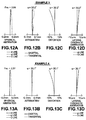
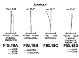
- Respective aberrations of image pickup lens of each of Examples 1 to 9 are shown in Figures 10A to 10D, 11A to 11D , 12A to 12D, 13A to 13D , 14A to 14D, 15A to 15D , 16A to 16D, 17A to 17D , and 18A to 18D respectively.
- Example 1 Diagrams of spherical aberration, astigmatism, distortion, and lateral chromatic aberration of image pickup lens of Example 1 are shown in Figures 10A to 10D respectively.
- the "Fno.” in spherical aberration diagram represents an F-number and " ⁇ " in the other diagrams represents a half angle of view.
- the distortion diagram illustrates an amount of displacement from an ideal image height obtained by f ⁇ tan ⁇ , in which f is a focal length of the entire lens system and ⁇ is a half angle of view (treated as a variable, 0 ⁇ ⁇ ⁇ ⁇ ).
- Each diagram shows an aberration with e-line (wavelength of 546.07 nm) as the reference wavelength.
- the diagrams of spherical aberration and lateral chromatic aberration also illustrate aberrations with respect to g-line (wavelength of 436 nm) and C-line (wavelength of 656.27 nm) .
- the image pickup lens of each of Examples 1 to 9 is formed of only a small number of four lenses, and can be produced compactly and inexpensively.
- each image pickup lens has a small F-number of about 2.0, a wide total angle of view of about 60°, and favorable optical performance with aberrations being satisfactorily corrected.
- These image pickup lenses may be used preferably in surveillance cameras, vehicle cameras for taking images of front, side, and rear of the vehicles, and the like.
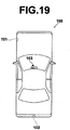
- Figure 19 illustrates automobile 100 in which an image pickup apparatus having an image pickup lens of the present invention is mounted.
- automobile 100 has vehicle exterior camera 101 for imaging a blind area on the front passenger seat side, vehicle exterior camera 102 for imaging a blind area on the rear side, and in-vehicle camera 103 attached to the rear side of a rearview mirror to image a view range identical to that of a driver.
- Vehicle exterior camera 101, vehicle exterior camera 102, and in-vehicle camera 103 are image pickup apparatuses according to an embodiment of the present invention, and include image pickup lenses of examples of the present invention and image sensors for converting optical images formed by the image pickup lenses to electrical signals.
- values of the radius of curvature, surface distance, refractive index, Abbe number, aspherical coefficient of each lens element are not limited to those shown in each of the numeric value examples and may take other values.
- the application of the present invention is not limited to the vehicle camera and the invention may also be applied, for example, to cameras of portable terminal devices, surveillance cameras, and the like.
Description
- The present invention relates to an image pickup lens and an image pickup apparatus, and more particularly to an image pickup lens appropriate for use with a vehicle camera, portable terminal camera, surveillance camera, or the like having an image senor, such as a CCD (charge coupled device) or a CMOS (complementary metal oxide semiconductor), and an image pickup apparatus having the image pickup lens.
- Image sensors, such as CCD or CMOS devices, have recently been greatly downsized with increased pixel counts. Consequently, image pickup devices themselves have also been downsized and image pickup lenses to be mounted on the devices are required to be downsized and improved in performance. In the mean time, lenses used in vehicle cameras and surveillance cameras are required to have a high weather resistance so as to be usable under a sever environment, in addition to be inexpensive and light weighted.
- Conventional image pickup lenses with relatively fewer lenses known in the aforementioned fields include, for example, those described in Japanese Unexamined Patent Publication No.
H9 (1997)-189856 U.S Patent No. 7,760,444 (Patent Document 2), Japanese Patent No.3756114 U.S. Patent No. 7,009,783 (Patent Document 4).Patent Document 1 describes a five lens image pickup lens system in which a first lens on the most object side is a negative meniscus lens with a convex surface oriented to the obj ect side.Patent Documents Patent Document 4 describes a four lens image pickup lens system in which a first lens on the most object side is a negative meniscus lens with a concave surface oriented to the object side. DocumentUS 2002/196564 A1 discloses an image pickup lens having a four lens configuration in which a bi-concave first lens, a bi-convex second lens, a negative third lens being a meniscus lens and a positive fourth lens are disposed in this order from an object side, wherein the refractive index of the second lens with respect to d-line is nd=1.74330. - Document
US 2005/207024 A1 discloses an image pickup lens having a four lens configuration in which a bi-concave first lens, a bi-convex second lens, a bi-concave third lens, and a positive fourth lens are disposed in this order from an object side. In the mean time, requirements for the lenses in the fields described above have been getting strict year after year and the lenses need to satisfy a plurality of sophisticated conditions simultaneously. That is, a compact image pickup lens with fewer lenses, yet having a long back focus to allow a cover glass, filter, and the like to be inserted between the lens system and image sensor, having a small F-number that allows the use of the lens under low illumination, such as during night, ensuring a wide total angle of view of about 60°, and being satisfactorily corrected in aberration, has been sought. - For the image pickup lenses described in
Patent Document 1 andPatent Document 2, however, it is difficult to bring forward downsizing while ensuring a long back focus since the power of the first lens on the most object side is small. The image pickup lens described inPatent Document 3 has a large F-number of 3.5 which is inadequate for night time use. The image pickup lens described inPatent Document 4 has a somewhat large F-number of 2.8 and it is difficult to have a wide angle of view because the first lens on the most object side has a negative meniscus shape with a concave surface oriented to the object side. - In view of the circumstances described above, it is an object of the present invention to provide a compact image pickup lens, yet with a long back focus, a wide angle of view, a small F-number, and high optical performance. It is a further object of the present invention to provide an image pickup apparatus having the aforementioned image pickup lens.
- An image pickup lens of the present invention is an image pickup lens having a four lens configuration in which a bi-concave first lens, a bi-convex second lens, a bi-concave third lens, and a positive fourth lens are disposed in this order from an object side, wherein:
- at least one of the first, second, third, and fourth lenses has an aspherical surface on each side; and
- the image pickup lens satisfies Conditional Expression (1) given below when a refractive index of the second lens with respect to d-line is taken as Nd2.

- Preferably, the image pickup lens of the present invention satisfies any one of Conditional Expressions (2) to (6) given below or a combination of any two or more of them.


- R1: a radius of curvature of the first lens on the object side;
- R2; a radius of curvature of the first lens on the image side;
- f: a focal length of the entire lens system;
- vd1: an Abbe number of the first lens with respect to d-line;
- vd3: an Abbe number of the third lens with respect to d-line; and
- D12: a distance between the first and second lenses on an optical axis.
- In the image pickup lens of the present invention, an aperture may be disposed between the first and second lenses or between the second and third lenses.
- In the image pickup lens of the present invention, all of the lenses may be uncemented single lenses or the third and fourth lens may be cemented together.
- Preferably, in the image pickup lens of the present invention, the first lens is made of glass. Further, in the image pickup lens of the present invention, it is more preferable that all of the lenses are made of glass.
- The phrase "bi-concave lens" with respect to the first lens, "bi-convex lens" with respect to the second lens, "bi-concave lens" with respect to the third lens, or "positive lens" with respect to the fourth lens is applicable in a paraxial region if the lens is an aspherical lens, and if the first lens is an aspherical lens, radii of paraxial curvature are used as the radii of curvature in Conditional Expression (2) . As for the sign of the radii of curvature in Conditional Expression (2), a positive sign is used if the surface shape is convex toward the object side and a negative sign is used if the surface shape is convex toward the image side.
- An image pickup apparatus of the present invention is an apparatus that includes the image pickup lens described above.
- According to the present invention, an image pickup lens having a compact configuration of four lenses, yet with a long back focus, a wide angle of view, a small F-number, and favorable optical performance is realized through appropriate power arrangement, appropriate setting of the shape or power sign for each lens, inclusion of an aspherical lens, and satisfaction of Conditional Expression (1). Further, the present invention may also realize an image pickup apparatus having the image pickup lens described above.
-
-
Figure 1 is a cross-sectional view of an image pickup lens according to Example 1 of the present invention, illustrating a configuration thereof. -
Figure 2 is a cross-sectional view of an image pickup lens according to Example 2 of the present invention, illustrating a configuration thereof. -
Figure 3 is a cross-sectional view of an image pickup lens according to Example 3 of the present invention, illustrating a configuration thereof. -
Figure 4 is a cross-sectional view of an image pickup lens according to Example 4 of the present invention, illustrating a configuration thereof. -
Figure 5 is a cross-sectional view of an image pickup lens according to Example 5 of the present invention, illustrating a configuration thereof. -
Figure 6 is a cross-sectional view of an image pickup lens according to Example 6 of the present invention, illustrating a configuration thereof. -
Figure 7 is a cross-sectional view of an image pickup lens according to Example 7 of the present invention, illustrating a configuration thereof. -
Figure 8 is a cross-sectional view of an image pickup lens according to Example 8 of the present invention, illustrating a configuration thereof. -
Figure 9 is a cross-sectional view of an image pickup lens according to Example 9 of the present invention, illustrating a configuration thereof. -
Figure 10A to 10D illustrate respective aberrations of the image pickup lens according to Example 1 of the present invention. -
Figure 11A to 11D illustrate respective aberrations of the image pickup lens according to Example 2 of the present invention. -
Figure 12A to 12D illustrate respective aberrations of the image pickup lens according to Example 3 of the present invention. -
Figure 13A to 13D illustrate respective aberrations of the image pickup lens according to Example 4 of the present invention. -
Figure 14A to 14D illustrate respective aberrations of the image pickup lens according to Example 5 of the present invention. -
Figure 15A to 15D illustrate respective aberrations of the image pickup lens according to Example 6 of the present invention. -
Figure 16A to 16D illustrate respective aberrations of the image pickup lens according to Example 7 of the present invention. -
Figure 17A to 17D illustrate respective aberrations of the image pickup lens according to Example 8 of the present invention. -
Figure 18A to 18D illustrate respective aberrations of the image pickup lens according to Example 9 of the present invention. -
Figure 19 illustrates location of a vehicle image pickup apparatus according to an embodiment of the present invention. - Hereinafter, embodiments of the present invention will be described in detail with reference to the accompanying drawings.
Figures 1 to 9 are cross-sectional views of image pickup lenses according to embodiments of the present invention, illustrating example configurations thereof. The lenses shown inFigures 1 to 9 correspond respectively to lenses of Examples 1 to 9, to be described later. Basic configurations of examples shown inFigure 1 to 9 are identical and are illustrated in the same manner. Therefore, description of image pickup lenses according to embodiments of the present invention will be made with reference mainly to the example configuration inFigure 1 . - The image pickup lens shown in
Figure 1 has a four lens configuration in which first lens L1, second lens L2, third lens L3, and fourth lens L4 are disposed in this order from an object side. Aperture stop St may be disposed between the second lens L2 and third lens L3, as in the example illustrated inFigure 1 . But the position of aperture stop St in the image pickup lens of the present invention is not necessary limited to this. The illustrated aperture stop St is not necessarily depicted in an actual size and a shape inFigure 1 but its position on the optical axis is indicated. InFigure 1 , the left side is the object side and the right side is the image side and reference symbol Ri (i=1, 2, 3, -----) represents a radius of curvature of each lens surface and reference symbol Di (i=1, 2, 3, -----) represents a surface distance. - Note that
Figure 1 also showsimage sensor 5 disposed on image plane Sim, considering the case in which image pickup lens is applied to an image pickup apparatus. Theimage sensor 5 is a device that converts an optical image formed by image pickup lens to an electrical signal and is constituted, for example, by a CCD image sensor, a CMOS image sensor, or the like. - When the image pickup lens is applied to an image pickup apparatus, it is preferable that a cover glass, a low-pass filter, or an infrared light cut filter is provided according to the structure of the camera on which the lens is mounted, and
Figure 1 illustrates an example case in which a parallel plate optical member PP, assuming these, is provided between the most image side lens and image sensor 5 (image plane Sim). - In the image pickup lens of the present invention, first lens L1 is a bi-concave lens, second lens L2 is a bi-convex lens, third lens L3 is a bi-concave lens, and fourth lens L4 is a positive lens, in which at least one of the four lenses has an aspherical surface on each side. The surface shape and sign of each lens described herein are those in a paraxial region if the lens is an aspherical lens.
- Employment of a bi-concave lens, a bi-convex lens, and a bi-concave lens for first lens L1, second lens L2, and third lens L3 respectively allows refractive power of each lens to be increased and, thereby, the image pickup lens may be configured with a small number of lenses. Further, employment of a negative lens for first lens L1 on the most object side and a positive lens for fourth lens L4 on the most image side allows a long back focus. Arrangement of a bi-convex lens as second lens L2 and a bi-concave lens as third lens L3 between first lens L1 and fourth lens L4 allows field curvature and astigmatism to be eliminated. Further, employment of aspherical surfaces for a plurality of surfaces allows spherical aberration and distortion to be corrected satisfactorily, which is advantageous for realizing high optical performance while ensuring a wide angle and a small F-number.
- The present image pickup lens is configured so as to satisfy Conditional Expression (1) given below when the refractive index of second lens L2 with respect to d-line is taken as Nd2.

- In the present image pickup lens, it is preferable that relatively strong power is allocated to each lens because the image pickup lens is formed of only a small number of four lenses. In particular, it is preferable that strong power is allocated to second lens L2, which is a positive lens, among the lenses for chromatic aberration correction and downsizing. If Nd2 exceeds the lower limit of Conditional Expression (1), the curvature of the lens needs to be increased in order to increase the power, thereby causing difficulty in correcting field curvature and lateral chromatic aberration.
- It is more preferable that the present image pickup lens is configured so as to satisfy Conditional Expression (1-1) given below instead of Conditional Expression (1).

- Further, it is preferable that the present image pickup lens has any one of the following configurations or a combination of any two or more of them.
- Preferably, the image pickup lens satisfies Conditional Expression (2) given below when a radius of curvature of first lens L1 on the object side is taken as R1 and a radius of curvature of first lens L1 on the image side is taken as R2.

- Preferably, the image pickup lens satisfies Conditional Expression (3) given below when a focal length of the entire lens system is taken as f and a focal length of first lens L1 is taken as f1.

- Here, it is more preferable that the image pickup lens satisfies Conditional Expression (3-1) given below instead of Conditional Expression (3).

- Preferably, the image pickup lens satisfies Conditional Expression (4) given below when an Abbe number of first lens L1 with respect to d-line is taken as vd1.

- Preferably, the image pickup lens satisfies Conditional Expression (5) given below when a focal length of the entire lens system is taken as f and a distance between first lens L1 and second lens L2 on the optical axis is taken as D12.

- If D12/f exceeds the upper limit of Conditional Expression (5), the size of the entire lens system can not be reduced. In the present image pickup lens, a long back focus is ensured by first broadening light beam through first lens L1 and then causing focusing the light beam broadened to a certain extent through second lens L2. Consequently, if D12/f exceeds the lower limit of Conditional Expression (5), it is necessary to broaden a light beam while the light beam is passing through a short distance between first lens L1 and second lens L2, and the focal length of first lens L1 needs to be reduced, causing difficulty in correcting lateral chromatic aberration.
- Preferably, the image pickup lens satisfies Conditional Expression (6) given below when an Abbe number of third lens L3 with respect to d-line is taken as vd3.

- Here, it is more preferable that the image pickup lens satisfies Conditional Expression (6-1) given below instead of Conditional Expression (6).

- Preferably, fourth lens L4 is a bi-convex lens. Employment of a bi-convex lens for fourth lens L4 allows required positive power to be ensured in a system of a small number of lenses.
- Preferably, aperture stop St is disposed between first lens L1 and second lens L2 or between second lens L2 and third lens L3. If aperture stop St is disposed between first lens L1 and second lens L2, the exit pupil position may be set at a position remote from the imaging plane and high telecentricity may be provided easily. When aperture stop St is disposed between second lens L2 and third lens L3, the power distribution becomes substantially uniform between the obj ect side and image side of the aperture stop St, whereby generation of off-axis aberrations, such as astigmatism and distortion may be prevented.
- Further, the image pickup lens may have a four group four element configuration formed of four uncemented single lenses or a three group four element configuration in which first and second lenses L1, L2 are single lenses, while third and fourth lenses L3, L4 are cemented together. The four group four element configuration is advantageous in environmental resistance because no cement is used, in addition to low cost in comparison with the case in which lenses are cemented and high design freedom. In the mean time, the three group four element configuration may correct axial chromatic aberration and lateral chromatic aberration more satisfactorily in comparison with the case in which the image pickup lese is formed of only single lenses.
- Preferably, first lens L1 disposed on the most object side is made of a glass material. When first lens L1 is made of a glass material having higher environmental resistance than that of a plastic material, the environmental resistance of the lens system may be ensured. When the image pickup lens of the present invention is expected to be used under a severe environment, such as in a vehicle camera or the like, it is preferable that first lens L1 disposed on the most object side is made of a material which is resistant to surface degradation by the weather, temperature change by direct sunlight, and chemicals, such as grease, detergent, and the like, that is, a material having high water resistance, weather resistance, acid resistance, chemical resistance, and the like. Use of a glass material may satisfy these requirements. Further, as the material of first lens L1, for example, a transparent ceramic material may also be used. More specifically, for example, a material with water resistance of 1 by powder method defined by Japan Optical Glass Industries Association is preferably used. Further, it is preferable that all of the lenses of the system are made of a glass material or a transparent ceramic material in order to ensure higher environmental resistance.
- A protection means may be provided on the object side surface of first lens L1 for improving the strength, scratch resistance, and chemical resistance. In such a case, the material of first lens L1 may be a plastic material. The protection means may be a hard coating or a water-repellent coating.
- Any one of second lens L2, third lens L3, and fourth lens L4 or any combination thereof may be made of a plastic material. Use of a plastic material allows the lens system to be formed inexpensively and lightweight. Further, when an aspherical surface is provided, the aspherical surface shape may be shaped accurately and, thereby satisfactory optical performance may be ensured.
- In a case where a plastic material is used for any of second lens L2, third lens L3, and fourth lens L4, a so-called nano-composite material which is a composite of a plastic and fine particles smaller than a wavelength of light may be used. The refractive index and Abbe number of the nano-composite material may be changed according to the type and amount of the fine particles to be mixed. The use of the nano-composite material allows a material having a high refractive index or a small Abbe number, which heretofore has not been obtained by any plastic material, to be provided, whereby a lens having satisfactory optical performance may be manufactured.
- Note that a filter for cutting ultraviolet light to blue light or an IR (infrared) cut filter for cutting infrared light may be inserted between the lens system and
image sensor 5 according to the intended use of the image pickup lens. Alternatively, a coating having identical characteristics to those of the filters described above may be applied on a lens surface. Otherwise, a material that absorbs ultraviolet light, blue light, or infrared light may be used for any one of the lenses. -
Figure 1 illustrates an example case in which an optical member PP, representing various types of filters, is disposed between the lens system andimage sensor 5. Instead of this, each of the various types of filters may be disposed between each of the lenses. Alternatively, a coating that acts as the various types of filters may be applied on a lens surface of any of the lenses of the image pickup lens. - A light beam passing through outside of the effective diameter of each lens may possibly reach the image plane as stray light and become ghost. It is, therefore, preferable that the image pickup lens is provided with a light blocking means for blocking the stray light as required. As for the light blocking means, for example, an opaque coating material may be applied or an opaque plate may be provided on a portion of the image side surface of each lens outside of the effective diameter. Alternatively, an opaque plate may be provided in the optical path of a light beam that becomes stray light as the light blocking means. Otherwise, a hood or the like may be disposed at a position on the object side of the most object side lens.
- Further, a member, such as an aperture or the like, for blocking a marginal ray to the extent that does not cause a problem in the relative illumination may be disposed between each lens. The term "marginal ray" as used herein refers to a light beam of those from an object point outside of optical axis Z passing through a peripheral portion of the entrance pupil of an optical system. By disposing a member for blocking a marginal ray in this way, the quality in a peripheral portion of an image may be improved. Further, by blocking light that causes ghost, ghost may be reduced.
- Numerical examples of image pickup lens of the present invention will now be described. Cross-sectional views of image pickup lenses of Examples 1 to 9 are illustrated in
Figures 1 to 9 respectively. In each ofFigures 1 to 9 , the left side is an object side and right side is an image side, and aperture stop St and optical member PP are also shown. Aperture stop St in each drawing is not necessarily depicted in an actual size and a shape but to indicate the position on optical axis Z. In each example, symbols Ri, Di (i=1, 2, 3, -----) in the lens cross-sectional view correspond to lens data Ri, Di to be described in the following. - Surface data of Lens data of the image pickup lens of Example 1 are shown in Table 1 and aspherical surface data are shown in Table 2. Likewise, surface data of lens data of the image pickup lenses of Examples 2 to Examples 9 and aspherical surface data are shown in Tables 3 to 18 respectively. Hereinafter, symbols in the tables will be described by way of Example 1, but symbols in Examples 2 to 9 are basically identical to those of Example 1.
- In the surface data of Table 1, Si column represents ith (i = 1, 2, 3, -----) surface number, which is gradually incremented toward image side with the surface of the component disposed on the most object side being taken as the first surface. The Ri column in Table 1 represents a radius of curvature of ith surface and the Di column represents a surface distance between ith surface and ith + 1 surface on optical axis Z. In the Ri column of Table 1, a positive sign is used if the surface is convex toward the object side and a negative sign is used if the surface is convex toward the image side. A surface distance between the final surface shown in the table and image plane Sim is indicated at the bottom of Di column.
- Further, in the surface data of Table 1, Ndj column represents a refractive index of jth lens (j = 1, 2, 3, -----) with respect to d-line(wavelength of 587.6 nm), which is gradually incremented toward the image side with the lens disposed at the most object side being taken as the first lens. The vdj column represents an Abbe number of jth optical element with respect to d-line. The surface data include aperture stop St and optical member PP, and the surface number field corresponding to the aperture stop St includes the phrase "(Aperture Stop)".
- In the surface data of Table 1, an asterisk mark is attached to the surface number of each aspherical surface and a value of radius of curvature adjacent to the optical axis (paraxial radius of curvature) is indicated as the radius of curvature of the aspherical surface. Aspherical surface data in Table 2 include the surface number, a paraxial curvature and aspherical coefficient of each aspherical surface. In the aspherical surface data of Table 2, a numerical value "E-n" (n: an integer). refers t0"×10-n" and "E+n" refers to "×10n", The aspherical surface coefficients represent the value of each of coefficients KA and Bm (m = 3, 4, 5, -----, 10) in the aspherical surface equation given below.

- Zd: depth of aspherical surface (a length of the vertical line from a point on the aspherical surface at height Y to a flat surface orthogonal to an optical axis to which the aspherical vertex contact),
- Y: height (distance from the optical axis to lens surface),
- C: paraxial curvature, and
- KA, Bm: aspherical coefficients (m = 3, 4, 5, -----, 10).
- Focal length f of the entire lens system of image pickup lens in each of Examples 1 to 9, focal length f1 of first lens L1, and values corresponding to Conditional Expressions (1) to (6) are shown in Table 19. The values shown in Table 19 are those with respect to d-line. Each of Examples 1 to 9 satisfies Conditional Expressions (1) to (6) .
[Table 19] EXAMPLE1 EXAMPLE2 EXAMPLE3 EXAMPLE4 EXAMPLE5 EXAMPLE6 EXAMPLE7 EXAMPLE8 EXAMPLE9 f 4.45 4.45 4.45 4.45 4.45 4.41 4.44 4.44 4.44 f1 -7.25 -7.72 -4.17 -3.97 -6.77 -5.24 -7.41 -6.39 5.07 (1) Nd2 1.69098 1.69098 1.38300 1.88300 1.88300 1.86400 1.69098 1.69098 1.86400 (3) f1/f -1.63 -1.74 -0.94 -0.89 -1.52 -1.19 -1.07 -1.44 -1.14 (4) ν d1. 61.2 61.2 63:0 61.2 70.2 70.2 56.0 61.2 61.2 (5) D12/f 1.41 1.37 0.71 0.56 1.15 1.13 1.29 1.38 1.18 (6) ν d3 25.5 25.5 18.9 18.9 18.9 18.9 25.5 25.1 18.9 - Tables 1 to 19 include numerical values rounded to a predetermined number of significant digits. As the unit for lengths, "mm" is used. But, this is only an example, and other appropriate units may also be used since identical optical performance may be obtained from an optical system when it is proportionally enlarged or reduced.
- Respective aberrations of image pickup lens of each of Examples 1 to 9 are shown in
Figures 10A to 10D, 11A to 11D ,12A to 12D, 13A to 13D ,14A to 14D, 15A to 15D ,16A to 16D, 17A to 17D , and18A to 18D respectively. - Here, description will be made by taking the aberration diagrams of Example 1 as example, but aberration diagrams of other Examples are identical to those of Example 1. Diagrams of spherical aberration, astigmatism, distortion, and lateral chromatic aberration of image pickup lens of Example 1 are shown in
Figures 10A to 10D respectively. The "Fno." in spherical aberration diagram represents an F-number and "ω" in the other diagrams represents a half angle of view. The distortion diagram illustrates an amount of displacement from an ideal image height obtained by f×tanϕ, in which f is a focal length of the entire lens system and ϕ is a half angle of view (treated as a variable, 0 ≤ ϕ ≤ ω). Each diagram shows an aberration with e-line (wavelength of 546.07 nm) as the reference wavelength. The diagrams of spherical aberration and lateral chromatic aberration also illustrate aberrations with respect to g-line (wavelength of 436 nm) and C-line (wavelength of 656.27 nm) . - As the data suggest, the image pickup lens of each of Examples 1 to 9 is formed of only a small number of four lenses, and can be produced compactly and inexpensively. In addition, each image pickup lens has a small F-number of about 2.0, a wide total angle of view of about 60°, and favorable optical performance with aberrations being satisfactorily corrected. These image pickup lenses may be used preferably in surveillance cameras, vehicle cameras for taking images of front, side, and rear of the vehicles, and the like.
- As a usage example,
Figure 19 illustratesautomobile 100 in which an image pickup apparatus having an image pickup lens of the present invention is mounted. InFigure 19 ,automobile 100 hasvehicle exterior camera 101 for imaging a blind area on the front passenger seat side,vehicle exterior camera 102 for imaging a blind area on the rear side, and in-vehicle camera 103 attached to the rear side of a rearview mirror to image a view range identical to that of a driver.Vehicle exterior camera 101,vehicle exterior camera 102, and in-vehicle camera 103 are image pickup apparatuses according to an embodiment of the present invention, and include image pickup lenses of examples of the present invention and image sensors for converting optical images formed by the image pickup lenses to electrical signals. - So far the present invention has been described by way of embodiments and examples, but the invention is not limited to the embodiments and examples described above and various modifications and changes may be made. For example, values of the radius of curvature, surface distance, refractive index, Abbe number, aspherical coefficient of each lens element are not limited to those shown in each of the numeric value examples and may take other values.
- Further, in the embodiment of the image pickup apparatus, the description has been made, with reference to a drawing, of a case in which the present invention is applied to a vehicle camera. But the application of the present invention is not limited to the vehicle camera and the invention may also be applied, for example, to cameras of portable terminal devices, surveillance cameras, and the like.
| EXAMPLE1 SURFACE DATA | ||||
| Si | Ri | Di | Ndj | ν dj |
| 1 | -19.1813 | 0.900 | 1.58913 | 61.2 |
| 2 | 5.5902 | 6.271 | ||
| 3* | 6.6214 | 3.000 | 1.69098 | 53.0 |
| 4* | -4.6569 | 0.704 | ||
| 5(APERTURE STOP) | ∞ | 0.482 | ||
| 6* | -19.6807 | 0.701 | 1.61400 | 25.5 |
| 7* | 2.1692 | 0.400 | ||
| 8* | 2.8066 | 2.000 | 1.53391 | 56.0 |
| 9* | -10.0261 | 4.088 | ||
| 10 | ∞ | 0.400 | 1.51680 | 64.2 |
| 11 | ∞ | 0.500 | ||

| EXAMPLE2 SURFACE DATA | ||||
| Si | Ri | Di | Ndj | ν dj |
| 1 | -15.1912 | 0.900 | 1.58913 | 61.2 |
| 2 | 6.6386 | 6.078 | ||
| 3* | 6.5919 | 2.998 | 1.69098 | 53.0 |
| 4* | -4.7202 | 0.331 | ||
| 5(APERTURE STOP) | ∞ | 1.074 | ||
| 6* | -1.9901 | 0.701 | 1.61400 | 25.5 |
| 7* | 10.5287 | 0.203 | ||
| 8* | 2.2688 | 2.000 | 1.53391 | 56.0 |
| 9* | -8.8239 | 4.201 | ||
| 10 | ∞ | 0.500 | 1.51680 | 64.2 |
| 11 | ∞ | 0.500 | ||

| EXAMPLE3 SURFACE DATA | ||||
| Si | Ri | Di | Ndj | ν dj |
| 1* | -13.7687 | 0.900 | 1.69098 | 53.0 |
| 2 | 3.7445 | 2.974 | ||
| 3(APERTURE STOP) | ∞ | 0.201 | ||
| 4 | 4.9436 | 2.998 | 1.88300 | 40.8 |
| 5 | -11.5885 | 1.098 | ||
| 6 | -4.1105 | 0.701 | 1.92286 | 18.9 |
| 7 | 198.2276 | 0.200 | ||
| 8* | 5.5822 | 2.000 | 1.69098 | 53.0 |
| g* | -6.1015 | 5.688 | ||
| 10 | ∞ | 0.250 | 1.51680 | 64.2 |
| 11 | ∞ | 0.49.7 | ||
| EXAMPLE3 ASPHERICAL SURFACE DATA | |||
| S1 | S8 | S9 | |
| C | -7.282830551E-02 | 1.791417311E-01 | -1.638941766E-01 |
| KA | 2.000000000E+01 | 3.627027355E+00 | 5.018784265E-00 |
| B3 | -2,233114714E-04 | -3.589776921E-03 | 9.896544867E-04 |
| B4 | 2.639754213E-03 | 6.0840694095-03 | 2.898307826E-04 |
| B5 | -1.153737732E-03 | -8.672323595E-03 | 9.758104190E-03 |
| B6 | 3.511654658E-04 | 4.158164469E-04 | -4.449806970E-03 |
| B7 | 0.000000000E+00 | 7.032788895E-03 | -1.734720510E-03 |
| B8 | 0.000000000E+00 | -5.350731115E-03 | 3.071945302E-03 |
| B9 | 0.000000000E+00 | 1.688506094E-03 | -1.282136406E-03 |
| B10 | 0.000000000E+00 | -2.029192614E-04 | 1.918293440E-04 |
| EXAMPLE4 SURFACE DATA | ||||
| Si | Ri | Di | Ndj | ν dj |
| 1 | -15.0219 | 0.900 | 1.58913 | 61.2 |
| 2 | 2.8336 | 2.266 | ||
| 3(APERTURE STOP) | ∞ | 0.216 | ||
| 4 | 6.4202 | 6.000 | 1.88300. | 40.8 |
| 5 | -6.3159 | 0.934 | ||
| 6 | -4.7096 | 0.732 | 1.92286 | 18.9 |
| 7 | 82.2091 | 0.200 | ||
| 8* | 5.1718 | 2.000 | 1.69098 | 53.0 |
| 9* | -8.3348 | 5.663 | ||
| 10 | ∞ | 0.200 | 1.51680 | 64.2 |
| 11 | ∞ | 0.500 | ||
| EXAMPLE4 ASPHERICAL SURFACE DATA | ||
| S8 | S9 | |
| C | 1.933558343E-01 | -1.199788131E-01 |
| KA | 9.530361610E-01 | -8.993034151E+00 |
| B3 | -4.830080884E-04 | -4.717932764E-04 |
| B4 | 3.054113665E-03 | 4.907588250E-03 |
| B5 | 3.710340621E-04 | 1.115071662E-03 |
| B6 | -1.072789356E-03 | -3.344862971E-04 |
| B7 | 1.570986744E-03 | -9.715759839E-04 |
| B8 | -8.252176837E-04 | 2.117567352E-03 |
| B9 | 2.023334916E-04 | -1.181394083E-03 |
| B10 | -1.494283234E-05 | 2.356282809E-04 |
| EXAMPLES SURFACE DATA | ||||
| Si | Ri | Di | Ndj | ν dj |
| 1 | -19.8809 | 0.900 | 1.48749 | 70.2- |
| 2 | 4.0158 | 4.939 | ||
| 3(APERTURE STOP) | ∞ | 0.202 | ||
| 4 | 4.5092 | 2.914 | 1.88300 | 40.8 |
| 5 | -26.1775 | 0.567 | ||
| 6 | -8.7832 | 0.700 | 1.92286 | 18.9 |
| 7 | 5.9625 | 0.204 | ||
| 8* | 4.0404 | 2.000 | 1.80348 | 40.4 |
| 9* | -16.4640 | 4.193 | ||
| 10 | ∞ | 0.400 | 1.51680 | 64.2 |
| 11 | ∞ | 0.500 | ||
| EXAMPLE5 SURFACE DATA | ||
| S8 | S9 | |
| C | 2.474993399E-01 | -6.073847948E-02 |
| KA | 2.649144471E+00 | 1.983468751E+01 |
| B3 | -4.652144836E-03 | -1.919688115E-03 |
| B4 | 9.895083359E-03 | 3.321459082E-03 |
| B5 | -2.276779822E-02 | 1.305029618E-02 |
| B6 | 9.953513298E-03 | -1.689461530E-02 |
| B7 | 8.074522583E-03 | 8.162432445E-03 |
| 88 | -1.171582453E-02 | -1.049080871E-04 |
| B9 | 5.106903139E-03 | -1.050520151E-03 |
| B10 | -8.141031646E-04. | 2.189556070E-04 |
| EXAMPLE6 SURFACE DATA | ||||
| Si | Ri | Di | Ndj | ν dj |
| 1 | -200.0000 | 0.900 | 1.48749 | 70.2 |
| 2 | 2.5907 | 2.792 | ||
| 3(APERTURE STOP) | ∞ | 2.187 | ||
| 4* | 8.0847 | 6.000 | 1.86400 | 40.6 |
| 5* | -5.7337 | 0.571 | ||
| 6 | -15.1508 | 1.500 | 1.92286 | 18.9 |
| 7 | 7.3593 | 2.000 | 1.51823 | 59.0 |
| 8 | -6.5795 | 5.55.6 | ||
| 9 | ∞ | 0.450 | 1.51680 | 64.2 |
| 10 | ∞ | 0.500 | ||
| EXAMPLE6 ASPHERICAL SURFACE DATA | ||
| S4 | S5 | |
| C | 1.236910023E-01 | -1.744079772E-01 |
| KA | -3.343613690E+00 | -8.647964969E+00 |
| B3 | -4.32696615E-03 | -8.1526.48161E-04 |
| B4 | 7.072232873E-03 | -6.695362870E-03 |
| B5 | -3.018643254E-03 | 4.426437184E-03 |
| B6 | -6.424876160E-04 | -5.336337911E-04 |
| B7 | 1.622824097E-03 | -1.429.284868E-03 |
| B8 | -7.962610231E-04 | 1.181065962E-03 |
| B9 | 1.756520284E-04 | -3.688260630E-04 |
| B10 | -1.474234856E-05 | 4.324574741E-051 |
| EXAMPLE7 SURFACE DATA | ||||
| Si | Ri | Di | Ndj | ν dj |
| 1* | -130.9654 | 0.900 | 1.53391 | 56.0 |
| 2* | 4.0913 | 5.754 | ||
| 3* | 6.3710 | 2.998 | 1.69098 | 53.0 |
| 4* | -4.8659 | 0.300 | ||
| 5(ARERTURE STOP) | ∞ | 1.146 | ||
| 6* | -1.7536 | 0.701 | 1.61400 | 25.5 |
| 7* | 10.0777 | 0.201 | ||
| 8* | 2.0947 | 2.003 | 1.53391 | 56.0 |
| 9* | -6.3120 | 4.529 | ||
| 10 | ∞ | 0.400 | 1.51680 | 64.2 |
| 11 | ∞ | 0.500 | ||

| EXAMPLE8 SURFACE DATA | ||||
| Si | Ri | Di | Ndj | ν dj |
| 1 | -34.6341 | 0.900 | 1.59913 | 61.2 |
| 2 | 4.2660 | 6.138 | ||
| 3* | 5.0000 | 6.000 | 1.69098 | 53.0 |
| 4* | -4.0522 | 0.300 | ||
| 5(APERTURE STOP) | ∞ | 0.795 | ||
| 6* | -2.4009 | 0.701 | 1.90200 | 25.1 |
| 7* | 28.6388 | 0.204 | ||
| 8* | 2.6133 | 2.000 | 1.56871 | 58.6 |
| 9* | -13.9652 | 4.263 | ||
| 10 | ∞ | 0.400 | 1.51680 | 64.2 |
| 11 | ∞ | 0.500 | ||

| EXAMPLE9 SURFACE DATA | ||||
| Si | Ri | Di | Ndj | ν dj |
| 1 | -200.0000 | 0.900 | 1.58913 | 61.2 |
| 2 | 3.0356 | 5.027 | ||
| 3(APERTURE STOP) | ∞ | 0.234 | ||
| 4* | 5.8064 | 3.000 | 1.86400 | 40.6 |
| 5* | -7.0066 | 0.578 | ||
| 6 | -12.6813 | 0.761 | 1.92288 | 18.9 |
| 7 | 6.1165 | 0.217 | ||
| 8 | 9.3880 | 2.000. | 1.62299 | 58.2 |
| 9 | -6.4585 | 5.847 | ||
| 10 | ∞ | 0.450 | 1.51680 | 64.2 |
| 11 | ∞ | 0.500 | ||
| EXAMPLE9 ASPHERICAL SURFACE DATA | ||
| S4 | S5 | |
| C | 1.722233689E-01 | -1.427223275E-01 |
| KA | 8.423177372E-01 | -1.733952824E+00 |
| B3 | -1.520154484E-03 | 9.823966293E-05 |
| B4 | 2.662519750E-03 | 3.370229172E-04 |
| B5 | -9.758866928E-04 | 1.893714011E-03 |
| B6 | -9.519067904E-04 | 2.972914701E-04 |
| B7 | 1.245454952E-03 | -1.431260743E-03 |
| B8 | -5.159403747E-04 | 9.742702943E-04 |
| B9 | 9.677178223E-05 | -2.860958559E-04 |
| B10 | -6.158874156E-06 | 3.596274216E-05 |
Claims (12)
- An image pickup lens having a four lens configuration in which a bi-concave first lens (L1), a bi-convex second lens (L2), a bi-concave third lens (L3), and a positive fourth lens (L4) are disposed in this order from an object side, wherein:at least one of the first, second, third, and fourth lenses has an aspherical surface on each side; andthe image pickup lens satisfies Conditional Expression (1) given below when a refractive index of the second lens with respect to d-line is taken as Nd2.

- The image pickup lens of Claim 1, characterized in that the image pickup lens satisfies Conditional Expression (2) given below when radii of curvature of the first lens (L1) on the object and image sides are taken as R1 and R2 respectively.

- The image pickup lens of claim 1 or 2, characterized in that the image pickup lens satisfies Conditional Expression (3) given below when a focal length of the entire lens system is taken as f and a focal length of the first lens (L1) is taken as f1.

- The image pickup lens of any of claims 1 to 3, characterized in that the image pickup lens satisfies Conditional Expression (4) given below when an Abbe number of the first lens (L1) with respect to d-line is taken as vd1.

- The image pickup lens of any of claims 1 to 4, characterized in that the image pickup lens satisfies Conditional Expression (5) given below when a focal length of the entire lens system is taken as f and a distance between the first (L1) and second (L2) lenses on an optical axis is taken as D12.

- The image pickup lens of any of claims 1 to 5, characterized in that the image pickup lens satisfies Conditional Expression (6) given below when an Abbe number of the third lens (L3) with respect to d-line is taken as vd3.

- The image pickup lens of any of claims 1 to 6, characterized in that an aperture is disposed between the first (L1) and second (L2) lenses.
- The image pickup lens of any of claims 1 to 6, characterized in that an aperture is disposed between the second (L2) and third (L3) lenses.
- The image pickup lens of any of claims 1 to 7, characterized in that the third (L3) and fourth (L4) lenses are cemented together.
- The image pickup lens of any of claims 1 to 9, characterized in that the first lens (L1) is made of glass.
- The image pickup lens of any of claims 1 to 10, characterized in that all of the lenses are made of glass.
- An image pickup apparatus, comprising the image pickup lens of any of claims 1 to 11.
Applications Claiming Priority (1)
| Application Number | Priority Date | Filing Date | Title |
|---|---|---|---|
| JP2010129519A JP2011257462A (en) | 2010-06-07 | 2010-06-07 | Imaging lens and imaging device |
Publications (2)
| Publication Number | Publication Date |
|---|---|
| EP2392958A1 EP2392958A1 (en) | 2011-12-07 |
| EP2392958B1 true EP2392958B1 (en) | 2018-08-29 |
Family
ID=44503518
Family Applications (1)
| Application Number | Title | Priority Date | Filing Date |
|---|---|---|---|
| EP11168802.4A Not-in-force EP2392958B1 (en) | 2010-06-07 | 2011-06-06 | Image pickup lens and image pickup apparatus |
Country Status (4)
| Country | Link |
|---|---|
| US (1) | US8508862B2 (en) |
| EP (1) | EP2392958B1 (en) |
| JP (1) | JP2011257462A (en) |
| CN (1) | CN102269863A (en) |
Families Citing this family (13)
| Publication number | Priority date | Publication date | Assignee | Title |
|---|---|---|---|---|
| TWI516790B (en) | 2012-08-27 | 2016-01-11 | 玉晶光電股份有限公司 | Optical imaging lens and the application of the lens of the electronic device |
| US20140085532A1 (en) * | 2012-09-24 | 2014-03-27 | Caldwell Photographic, Inc. | Corrective optical systems and methods |
| CN103123414A (en) | 2012-11-15 | 2013-05-29 | 玉晶光电(厦门)有限公司 | Portable electronic device and optical imaging lens of portable electronic device |
| TWI471588B (en) | 2012-12-28 | 2015-02-01 | 玉晶光電股份有限公司 | Mobile device and optical imaging lens thereof |
| KR101429892B1 (en) * | 2013-04-10 | 2014-08-13 | 주식회사 세코닉스 | Compact type wide angle lens system |
| CN103969791B (en) * | 2013-12-09 | 2016-05-25 | 玉晶光电(厦门)有限公司 | Optical imaging lens and apply the electronic installation of this camera lens |
| JP6557137B2 (en) * | 2015-12-25 | 2019-08-07 | 株式会社タムロン | Imaging lens and imaging apparatus |
| CN106680973B (en) * | 2017-01-22 | 2022-11-18 | 东莞市宇瞳光学科技股份有限公司 | Miniaturized large-view-field high-definition athermal prime lens |
| JP2018173459A (en) * | 2017-03-31 | 2018-11-08 | パナソニックIpマネジメント株式会社 | Imaging device, optical component, and imaging system |
| WO2019029153A1 (en) | 2017-08-07 | 2019-02-14 | 浙江舜宇光学有限公司 | Wide-angle lens and imaging device |
| TWI689746B (en) | 2019-03-22 | 2020-04-01 | 大立光電股份有限公司 | Optical imaging system, image capturing unit and electronic device |
| JP6698923B2 (en) * | 2019-07-11 | 2020-05-27 | 株式会社タムロン | Imaging lens and imaging device |
| CN112666679B (en) * | 2019-10-16 | 2022-03-18 | 比亚迪股份有限公司 | Camera module of mobile communication equipment and mobile communication equipment with camera module |
Family Cites Families (11)
| Publication number | Priority date | Publication date | Assignee | Title |
|---|---|---|---|---|
| JPH09189856A (en) | 1995-11-10 | 1997-07-22 | Asahi Optical Co Ltd | Photographing lens |
| JP4812957B2 (en) * | 2001-03-29 | 2011-11-09 | 富士フイルム株式会社 | Wide angle single focus lens |
| JP3756114B2 (en) | 2001-12-25 | 2006-03-15 | 株式会社コダックデジタルプロダクトセンター | Retro focus lens |
| JP3411565B1 (en) | 2002-07-30 | 2003-06-03 | マイルストーン株式会社 | Imaging lens |
| JP2005189711A (en) * | 2003-12-26 | 2005-07-14 | Seiko Precision Inc | Variable magnification lens |
| JP4689966B2 (en) | 2004-03-17 | 2011-06-01 | オリンパス株式会社 | Zoom lens and electronic imaging apparatus having the same |
| JP2006023437A (en) * | 2004-07-07 | 2006-01-26 | Olympus Corp | Variable power optical system and electronic apparatus using same |
| JP2006171212A (en) * | 2004-12-14 | 2006-06-29 | Nidec Copal Corp | Zoom lens |
| US7768716B2 (en) * | 2005-02-21 | 2010-08-03 | Olympus Corporation | Zoom optical system and electronic equipment using the same |
| JP2007322656A (en) * | 2006-05-31 | 2007-12-13 | Fujinon Corp | Wide-angle imaging lens |
| JP2009014947A (en) | 2007-07-04 | 2009-01-22 | Olympus Imaging Corp | Image-forming optical system and imaging apparatus using the same |
-
2010
- 2010-06-07 JP JP2010129519A patent/JP2011257462A/en not_active Abandoned
-
2011
- 2011-06-06 US US13/153,979 patent/US8508862B2/en active Active
- 2011-06-06 EP EP11168802.4A patent/EP2392958B1/en not_active Not-in-force
- 2011-06-07 CN CN2011101506869A patent/CN102269863A/en active Pending
Also Published As
| Publication number | Publication date |
|---|---|
| US20110299178A1 (en) | 2011-12-08 |
| EP2392958A1 (en) | 2011-12-07 |
| US8508862B2 (en) | 2013-08-13 |
| CN102269863A (en) | 2011-12-07 |
| JP2011257462A (en) | 2011-12-22 |
Similar Documents
| Publication | Publication Date | Title |
|---|---|---|
| EP2392958B1 (en) | Image pickup lens and image pickup apparatus | |
| EP1906223B1 (en) | Wide-angle compact imaging lens with three single lenses | |
| EP1947497B1 (en) | Compact fisheye objective lens | |
| US8355215B2 (en) | Image pickup lens and image pickup apparatus | |
| JP5042767B2 (en) | Imaging lens and imaging apparatus | |
| EP2012162B1 (en) | Imaging lens and imaging device | |
| EP2330450B1 (en) | Imaging lens and imaging apparatus | |
| JP5065159B2 (en) | Imaging lens and imaging apparatus | |
| EP2343587B1 (en) | Imaging lens and imaging apparatus | |
| EP1903368B1 (en) | Wide-angle imaging lens, imaging device and camera module | |
| EP2354829B1 (en) | Imaging lens and imaging apparatus | |
| EP2354830B1 (en) | Imaging lens and imaging apparatus | |
| JP5479702B2 (en) | Imaging lens and imaging apparatus | |
| JP6066424B2 (en) | Imaging lens and imaging apparatus | |
| JP5224455B2 (en) | Imaging lens and imaging apparatus | |
| JP5399306B2 (en) | Imaging lens and imaging apparatus | |
| JP2009092798A (en) | Imaging lens and imaging device | |
| JP2009086644A (en) | Imaging lens and imaging apparatus | |
| JP2008233610A (en) | Imaging lens and imaging device equipped with the imaging lens | |
| JP2009098322A (en) | Imaging lens and imaging apparatus | |
| JP2009145809A (en) | Image pickup lens and image pickup apparatus | |
| EP2642325B1 (en) | Image pickup lens and image pickup device | |
| JP5313566B2 (en) | Imaging lens and imaging apparatus using the same | |
| JP5486408B2 (en) | Imaging lens and imaging apparatus | |
| JP2011257640A (en) | Imaging lens and imaging apparatus |
Legal Events
| Date | Code | Title | Description |
|---|---|---|---|
| AK | Designated contracting states |
Kind code of ref document: A1 Designated state(s): AL AT BE BG CH CY CZ DE DK EE ES FI FR GB GR HR HU IE IS IT LI LT LU LV MC MK MT NL NO PL PT RO RS SE SI SK SM TR |
|
| AX | Request for extension of the european patent |
Extension state: BA ME |
|
| PUAI | Public reference made under article 153(3) epc to a published international application that has entered the european phase |
Free format text: ORIGINAL CODE: 0009012 |
|
| 17P | Request for examination filed |
Effective date: 20120511 |
|
| GRAJ | Information related to disapproval of communication of intention to grant by the applicant or resumption of examination proceedings by the epo deleted |
Free format text: ORIGINAL CODE: EPIDOSDIGR1 |
|
| STAA | Information on the status of an ep patent application or granted ep patent |
Free format text: STATUS: GRANT OF PATENT IS INTENDED |
|
| GRAP | Despatch of communication of intention to grant a patent |
Free format text: ORIGINAL CODE: EPIDOSNIGR1 |
|
| INTG | Intention to grant announced |
Effective date: 20180320 |
|
| RIN1 | Information on inventor provided before grant (corrected) |
Inventor name: KITAHARA, YU |
|
| GRAS | Grant fee paid |
Free format text: ORIGINAL CODE: EPIDOSNIGR3 |
|
| GRAA | (expected) grant |
Free format text: ORIGINAL CODE: 0009210 |
|
| STAA | Information on the status of an ep patent application or granted ep patent |
Free format text: STATUS: THE PATENT HAS BEEN GRANTED |
|
| AK | Designated contracting states |
Kind code of ref document: B1 Designated state(s): AL AT BE BG CH CY CZ DE DK EE ES FI FR GB GR HR HU IE IS IT LI LT LU LV MC MK MT NL NO PL PT RO RS SE SI SK SM TR |
|
| REG | Reference to a national code |
Ref country code: GB Ref legal event code: FG4D |
|
| REG | Reference to a national code |
Ref country code: CH Ref legal event code: EP |
|
| REG | Reference to a national code |
Ref country code: AT Ref legal event code: REF Ref document number: 1035798 Country of ref document: AT Kind code of ref document: T Effective date: 20180915 |
|
| REG | Reference to a national code |
Ref country code: IE Ref legal event code: FG4D |
|
| REG | Reference to a national code |
Ref country code: DE Ref legal event code: R096 Ref document number: 602011051474 Country of ref document: DE |
|
| REG | Reference to a national code |
Ref country code: NL Ref legal event code: MP Effective date: 20180829 |
|
| REG | Reference to a national code |
Ref country code: LT Ref legal event code: MG4D |
|
| PG25 | Lapsed in a contracting state [announced via postgrant information from national office to epo] |
Ref country code: LT Free format text: LAPSE BECAUSE OF FAILURE TO SUBMIT A TRANSLATION OF THE DESCRIPTION OR TO PAY THE FEE WITHIN THE PRESCRIBED TIME-LIMIT Effective date: 20180829 Ref country code: GR Free format text: LAPSE BECAUSE OF FAILURE TO SUBMIT A TRANSLATION OF THE DESCRIPTION OR TO PAY THE FEE WITHIN THE PRESCRIBED TIME-LIMIT Effective date: 20181130 Ref country code: SE Free format text: LAPSE BECAUSE OF FAILURE TO SUBMIT A TRANSLATION OF THE DESCRIPTION OR TO PAY THE FEE WITHIN THE PRESCRIBED TIME-LIMIT Effective date: 20180829 Ref country code: BG Free format text: LAPSE BECAUSE OF FAILURE TO SUBMIT A TRANSLATION OF THE DESCRIPTION OR TO PAY THE FEE WITHIN THE PRESCRIBED TIME-LIMIT Effective date: 20181129 Ref country code: NL Free format text: LAPSE BECAUSE OF FAILURE TO SUBMIT A TRANSLATION OF THE DESCRIPTION OR TO PAY THE FEE WITHIN THE PRESCRIBED TIME-LIMIT Effective date: 20180829 Ref country code: IS Free format text: LAPSE BECAUSE OF FAILURE TO SUBMIT A TRANSLATION OF THE DESCRIPTION OR TO PAY THE FEE WITHIN THE PRESCRIBED TIME-LIMIT Effective date: 20181229 Ref country code: RS Free format text: LAPSE BECAUSE OF FAILURE TO SUBMIT A TRANSLATION OF THE DESCRIPTION OR TO PAY THE FEE WITHIN THE PRESCRIBED TIME-LIMIT Effective date: 20180829 Ref country code: FI Free format text: LAPSE BECAUSE OF FAILURE TO SUBMIT A TRANSLATION OF THE DESCRIPTION OR TO PAY THE FEE WITHIN THE PRESCRIBED TIME-LIMIT Effective date: 20180829 Ref country code: NO Free format text: LAPSE BECAUSE OF FAILURE TO SUBMIT A TRANSLATION OF THE DESCRIPTION OR TO PAY THE FEE WITHIN THE PRESCRIBED TIME-LIMIT Effective date: 20181129 |
|
| REG | Reference to a national code |
Ref country code: AT Ref legal event code: MK05 Ref document number: 1035798 Country of ref document: AT Kind code of ref document: T Effective date: 20180829 Ref country code: DE Ref legal event code: R081 Ref document number: 602011051474 Country of ref document: DE Owner name: NANCHANG O-FILM OPTICAL-ELECTRONIC TECH CO., L, CN Free format text: FORMER OWNER: FUJIFILM CORPORATION, TOKYO, JP Ref country code: DE Ref legal event code: R081 Ref document number: 602011051474 Country of ref document: DE Owner name: TIANJIN O-FILM OPTO ELECTRONICS CO., LTD., CN Free format text: FORMER OWNER: FUJIFILM CORPORATION, TOKYO, JP |
|
| PG25 | Lapsed in a contracting state [announced via postgrant information from national office to epo] |
Ref country code: LV Free format text: LAPSE BECAUSE OF FAILURE TO SUBMIT A TRANSLATION OF THE DESCRIPTION OR TO PAY THE FEE WITHIN THE PRESCRIBED TIME-LIMIT Effective date: 20180829 Ref country code: ES Free format text: LAPSE BECAUSE OF FAILURE TO SUBMIT A TRANSLATION OF THE DESCRIPTION OR TO PAY THE FEE WITHIN THE PRESCRIBED TIME-LIMIT Effective date: 20180829 Ref country code: HR Free format text: LAPSE BECAUSE OF FAILURE TO SUBMIT A TRANSLATION OF THE DESCRIPTION OR TO PAY THE FEE WITHIN THE PRESCRIBED TIME-LIMIT Effective date: 20180829 Ref country code: AL Free format text: LAPSE BECAUSE OF FAILURE TO SUBMIT A TRANSLATION OF THE DESCRIPTION OR TO PAY THE FEE WITHIN THE PRESCRIBED TIME-LIMIT Effective date: 20180829 |
|
| PG25 | Lapsed in a contracting state [announced via postgrant information from national office to epo] |
Ref country code: AT Free format text: LAPSE BECAUSE OF FAILURE TO SUBMIT A TRANSLATION OF THE DESCRIPTION OR TO PAY THE FEE WITHIN THE PRESCRIBED TIME-LIMIT Effective date: 20180829 Ref country code: EE Free format text: LAPSE BECAUSE OF FAILURE TO SUBMIT A TRANSLATION OF THE DESCRIPTION OR TO PAY THE FEE WITHIN THE PRESCRIBED TIME-LIMIT Effective date: 20180829 Ref country code: IT Free format text: LAPSE BECAUSE OF FAILURE TO SUBMIT A TRANSLATION OF THE DESCRIPTION OR TO PAY THE FEE WITHIN THE PRESCRIBED TIME-LIMIT Effective date: 20180829 Ref country code: RO Free format text: LAPSE BECAUSE OF FAILURE TO SUBMIT A TRANSLATION OF THE DESCRIPTION OR TO PAY THE FEE WITHIN THE PRESCRIBED TIME-LIMIT Effective date: 20180829 Ref country code: CZ Free format text: LAPSE BECAUSE OF FAILURE TO SUBMIT A TRANSLATION OF THE DESCRIPTION OR TO PAY THE FEE WITHIN THE PRESCRIBED TIME-LIMIT Effective date: 20180829 Ref country code: PL Free format text: LAPSE BECAUSE OF FAILURE TO SUBMIT A TRANSLATION OF THE DESCRIPTION OR TO PAY THE FEE WITHIN THE PRESCRIBED TIME-LIMIT Effective date: 20180829 |
|
| PG25 | Lapsed in a contracting state [announced via postgrant information from national office to epo] |
Ref country code: DK Free format text: LAPSE BECAUSE OF FAILURE TO SUBMIT A TRANSLATION OF THE DESCRIPTION OR TO PAY THE FEE WITHIN THE PRESCRIBED TIME-LIMIT Effective date: 20180829 Ref country code: SK Free format text: LAPSE BECAUSE OF FAILURE TO SUBMIT A TRANSLATION OF THE DESCRIPTION OR TO PAY THE FEE WITHIN THE PRESCRIBED TIME-LIMIT Effective date: 20180829 Ref country code: SM Free format text: LAPSE BECAUSE OF FAILURE TO SUBMIT A TRANSLATION OF THE DESCRIPTION OR TO PAY THE FEE WITHIN THE PRESCRIBED TIME-LIMIT Effective date: 20180829 |
|
| REG | Reference to a national code |
Ref country code: DE Ref legal event code: R097 Ref document number: 602011051474 Country of ref document: DE |
|
| PLBE | No opposition filed within time limit |
Free format text: ORIGINAL CODE: 0009261 |
|
| STAA | Information on the status of an ep patent application or granted ep patent |
Free format text: STATUS: NO OPPOSITION FILED WITHIN TIME LIMIT |
|
| 26N | No opposition filed |
Effective date: 20190531 |
|
| PG25 | Lapsed in a contracting state [announced via postgrant information from national office to epo] |
Ref country code: SI Free format text: LAPSE BECAUSE OF FAILURE TO SUBMIT A TRANSLATION OF THE DESCRIPTION OR TO PAY THE FEE WITHIN THE PRESCRIBED TIME-LIMIT Effective date: 20180829 |
|
| PG25 | Lapsed in a contracting state [announced via postgrant information from national office to epo] |
Ref country code: MC Free format text: LAPSE BECAUSE OF FAILURE TO SUBMIT A TRANSLATION OF THE DESCRIPTION OR TO PAY THE FEE WITHIN THE PRESCRIBED TIME-LIMIT Effective date: 20180829 |
|
| REG | Reference to a national code |
Ref country code: CH Ref legal event code: PL |
|
| GBPC | Gb: european patent ceased through non-payment of renewal fee |
Effective date: 20190606 |
|
| REG | Reference to a national code |
Ref country code: BE Ref legal event code: MM Effective date: 20190630 |
|
| PG25 | Lapsed in a contracting state [announced via postgrant information from national office to epo] |
Ref country code: TR Free format text: LAPSE BECAUSE OF FAILURE TO SUBMIT A TRANSLATION OF THE DESCRIPTION OR TO PAY THE FEE WITHIN THE PRESCRIBED TIME-LIMIT Effective date: 20180829 |
|
| REG | Reference to a national code |
Ref country code: DE Ref legal event code: R082 Ref document number: 602011051474 Country of ref document: DE Representative=s name: MANITZ FINSTERWALD PATENT- UND RECHTSANWALTSPA, DE Ref country code: DE Ref legal event code: R081 Ref document number: 602011051474 Country of ref document: DE Owner name: TIANJIN O-FILM OPTO ELECTRONICS CO., LTD., CN Free format text: FORMER OWNER: NANCHANG O-FILM OPTICAL-ELECTRONIC TECH CO., LTD., JIANGXI, CN |
|
| PG25 | Lapsed in a contracting state [announced via postgrant information from national office to epo] |
Ref country code: GB Free format text: LAPSE BECAUSE OF NON-PAYMENT OF DUE FEES Effective date: 20190606 Ref country code: IE Free format text: LAPSE BECAUSE OF NON-PAYMENT OF DUE FEES Effective date: 20190606 |
|
| PG25 | Lapsed in a contracting state [announced via postgrant information from national office to epo] |
Ref country code: LI Free format text: LAPSE BECAUSE OF NON-PAYMENT OF DUE FEES Effective date: 20190630 Ref country code: CH Free format text: LAPSE BECAUSE OF NON-PAYMENT OF DUE FEES Effective date: 20190630 Ref country code: LU Free format text: LAPSE BECAUSE OF NON-PAYMENT OF DUE FEES Effective date: 20190606 Ref country code: BE Free format text: LAPSE BECAUSE OF NON-PAYMENT OF DUE FEES Effective date: 20190630 |
|
| PG25 | Lapsed in a contracting state [announced via postgrant information from national office to epo] |
Ref country code: FR Free format text: LAPSE BECAUSE OF NON-PAYMENT OF DUE FEES Effective date: 20190630 Ref country code: PT Free format text: LAPSE BECAUSE OF FAILURE TO SUBMIT A TRANSLATION OF THE DESCRIPTION OR TO PAY THE FEE WITHIN THE PRESCRIBED TIME-LIMIT Effective date: 20181229 |
|
| PG25 | Lapsed in a contracting state [announced via postgrant information from national office to epo] |
Ref country code: CY Free format text: LAPSE BECAUSE OF FAILURE TO SUBMIT A TRANSLATION OF THE DESCRIPTION OR TO PAY THE FEE WITHIN THE PRESCRIBED TIME-LIMIT Effective date: 20180829 |
|
| PG25 | Lapsed in a contracting state [announced via postgrant information from national office to epo] |
Ref country code: HU Free format text: LAPSE BECAUSE OF FAILURE TO SUBMIT A TRANSLATION OF THE DESCRIPTION OR TO PAY THE FEE WITHIN THE PRESCRIBED TIME-LIMIT; INVALID AB INITIO Effective date: 20110606 Ref country code: MT Free format text: LAPSE BECAUSE OF FAILURE TO SUBMIT A TRANSLATION OF THE DESCRIPTION OR TO PAY THE FEE WITHIN THE PRESCRIBED TIME-LIMIT Effective date: 20180829 |
|
| PG25 | Lapsed in a contracting state [announced via postgrant information from national office to epo] |
Ref country code: MK Free format text: LAPSE BECAUSE OF FAILURE TO SUBMIT A TRANSLATION OF THE DESCRIPTION OR TO PAY THE FEE WITHIN THE PRESCRIBED TIME-LIMIT Effective date: 20180829 |
|
| PGFP | Annual fee paid to national office [announced via postgrant information from national office to epo] |
Ref country code: DE Payment date: 20220620 Year of fee payment: 12 |
|
| REG | Reference to a national code |
Ref country code: DE Ref legal event code: R119 Ref document number: 602011051474 Country of ref document: DE |