JP5399306B2 - Imaging lens and imaging apparatus - Google Patents
Imaging lens and imaging apparatus Download PDFInfo
- Publication number
- JP5399306B2 JP5399306B2 JP2010074958A JP2010074958A JP5399306B2 JP 5399306 B2 JP5399306 B2 JP 5399306B2 JP 2010074958 A JP2010074958 A JP 2010074958A JP 2010074958 A JP2010074958 A JP 2010074958A JP 5399306 B2 JP5399306 B2 JP 5399306B2
- Authority
- JP
- Japan
- Prior art keywords
- lens
- curvature
- conditional expression
- imaging
- point
- Prior art date
- Legal status (The legal status is an assumption and is not a legal conclusion. Google has not performed a legal analysis and makes no representation as to the accuracy of the status listed.)
- Expired - Fee Related
Links
- 238000003384 imaging method Methods 0.000 title claims description 126
- 230000014509 gene expression Effects 0.000 claims description 124
- 230000003287 optical effect Effects 0.000 claims description 67
- 239000000463 material Substances 0.000 claims description 33
- 239000002131 composite material Substances 0.000 claims description 5
- 230000004075 alteration Effects 0.000 description 71
- 238000010586 diagram Methods 0.000 description 18
- 206010010071 Coma Diseases 0.000 description 13
- 230000005499 meniscus Effects 0.000 description 11
- 230000002093 peripheral effect Effects 0.000 description 11
- 239000011521 glass Substances 0.000 description 6
- 239000006059 cover glass Substances 0.000 description 5
- 230000000694 effects Effects 0.000 description 5
- 238000006243 chemical reaction Methods 0.000 description 3
- 230000006866 deterioration Effects 0.000 description 3
- 238000004519 manufacturing process Methods 0.000 description 3
- 239000000126 substance Substances 0.000 description 3
- 201000009310 astigmatism Diseases 0.000 description 2
- 230000009477 glass transition Effects 0.000 description 2
- 230000001681 protective effect Effects 0.000 description 2
- XLYOFNOQVPJJNP-UHFFFAOYSA-N water Substances O XLYOFNOQVPJJNP-UHFFFAOYSA-N 0.000 description 2
- 239000002253 acid Substances 0.000 description 1
- 230000009471 action Effects 0.000 description 1
- 230000015572 biosynthetic process Effects 0.000 description 1
- 230000000903 blocking effect Effects 0.000 description 1
- 230000015556 catabolic process Effects 0.000 description 1
- 238000001444 catalytic combustion detection Methods 0.000 description 1
- 239000000919 ceramic Substances 0.000 description 1
- 230000008859 change Effects 0.000 description 1
- 230000000295 complement effect Effects 0.000 description 1
- 238000006731 degradation reaction Methods 0.000 description 1
- 239000003599 detergent Substances 0.000 description 1
- 230000002708 enhancing effect Effects 0.000 description 1
- 230000004907 flux Effects 0.000 description 1
- 230000001771 impaired effect Effects 0.000 description 1
- 229910044991 metal oxide Inorganic materials 0.000 description 1
- 150000004706 metal oxides Chemical class 0.000 description 1
- 230000004048 modification Effects 0.000 description 1
- 238000012986 modification Methods 0.000 description 1
- 238000000465 moulding Methods 0.000 description 1
- 239000002114 nanocomposite Substances 0.000 description 1
- 239000003921 oil Substances 0.000 description 1
- 239000003973 paint Substances 0.000 description 1
- 239000002245 particle Substances 0.000 description 1
- 210000001747 pupil Anatomy 0.000 description 1
- 230000009467 reduction Effects 0.000 description 1
- 230000002940 repellent Effects 0.000 description 1
- 239000005871 repellent Substances 0.000 description 1
- 239000004065 semiconductor Substances 0.000 description 1
- -1 that is Substances 0.000 description 1
Images


Classifications
-
- G—PHYSICS
- G02—OPTICS
- G02B—OPTICAL ELEMENTS, SYSTEMS OR APPARATUS
- G02B13/00—Optical objectives specially designed for the purposes specified below
- G02B13/06—Panoramic objectives; So-called "sky lenses" including panoramic objectives having reflecting surfaces
-
- G—PHYSICS
- G02—OPTICS
- G02B—OPTICAL ELEMENTS, SYSTEMS OR APPARATUS
- G02B13/00—Optical objectives specially designed for the purposes specified below
- G02B13/001—Miniaturised objectives for electronic devices, e.g. portable telephones, webcams, PDAs, small digital cameras
- G02B13/0015—Miniaturised objectives for electronic devices, e.g. portable telephones, webcams, PDAs, small digital cameras characterised by the lens design
- G02B13/002—Miniaturised objectives for electronic devices, e.g. portable telephones, webcams, PDAs, small digital cameras characterised by the lens design having at least one aspherical surface
- G02B13/004—Miniaturised objectives for electronic devices, e.g. portable telephones, webcams, PDAs, small digital cameras characterised by the lens design having at least one aspherical surface having four lenses
Landscapes
- Physics & Mathematics (AREA)
- General Physics & Mathematics (AREA)
- Optics & Photonics (AREA)
- Lenses (AREA)
Description
本発明は、撮像レンズおよび撮像装置に関し、より詳しくは、CCD(Charge Coupled Device)やCMOS(Complementary Metal Oxide Semiconductor)等の撮像素子を用いた車載用カメラ、携帯端末用カメラ、監視カメラ等に使用されるのに好適な撮像レンズ、および該撮像レンズを備えた撮像装置に関するものである。 The present invention relates to an imaging lens and an imaging apparatus, and more particularly, to an in-vehicle camera, a mobile terminal camera, a surveillance camera, and the like using an imaging element such as a charge coupled device (CCD) or a complementary metal oxide semiconductor (CMOS). The present invention relates to an imaging lens suitable for the imaging, and an imaging device including the imaging lens.
CCDやCMOS等の撮像素子は近年非常に小型化及び高画素化が進んでいる。それとともに、これら撮像素子を備えた撮像機器本体も小型化が進み、それに搭載される撮像レンズにも良好な光学性能に加え、小型化が求められている。一方、車載用カメラや監視カメラ等の用途では、例えば全画角が180度を超えるような広角のレンズでありながら高い耐候性を持ち、小型で高性能を有するレンズが求められている。 In recent years, image sensors such as CCDs and CMOSs have been greatly reduced in size and pixels. At the same time, an image pickup apparatus body including these image pickup elements is also downsized, and an image pickup lens mounted thereon is required to be downsized in addition to good optical performance. On the other hand, in applications such as in-vehicle cameras and surveillance cameras, there is a demand for lenses that have a high weather resistance, a small size, and a high performance, although they are wide-angle lenses having a total angle of view exceeding 180 degrees.
上記分野において従来知られている比較的レンズ枚数の少ない撮像レンズとしては、例えば下記特許文献1〜4に記載のものがある。特許文献1〜4には、非球面レンズを含む4枚構成の撮像レンズが記載されている。
Examples of imaging lenses with a relatively small number of lenses that are conventionally known in the above fields include those described in
ところで、車載用カメラや監視カメラ等に搭載される撮像レンズに対する要求は年々厳しくなっており、小型であり、全画角が180度を超えるような広角化を満たした上で、さらに、結像領域周辺部まで良好な像が得られることが求められるようになっている。しかしながら、従来の小型のレンズ系では、全画角が180度を超えるような広角化を達成することと、結像領域周辺部まで良好な像を得ることの両方を同時に実現することは困難であった。 By the way, the requirements for imaging lenses mounted on in-vehicle cameras and surveillance cameras are becoming stricter year by year, and the size is small, and after satisfying widening such that the total angle of view exceeds 180 degrees, further imaging is performed. It has been demanded that a good image can be obtained up to the periphery of the region. However, with a conventional small lens system, it is difficult to achieve both widening the angle of view exceeding 180 degrees and obtaining a good image up to the periphery of the imaging region at the same time. there were.
本発明は、上記事情に鑑み、全画角が180度を超えるような広角化を達成しながら、小型に構成可能で、良好な光学性能を有し、結像領域周辺部まで良好な像を得ることが可能な撮像レンズ、および該撮像レンズを備えた撮像装置を提供することを目的とするものである。 In view of the above circumstances, the present invention can be configured in a small size while achieving a wide angle such that the total angle of view exceeds 180 degrees, has a good optical performance, and provides a good image up to the periphery of the imaging region. An object of the present invention is to provide an imaging lens that can be obtained, and an imaging device including the imaging lens.
本発明の撮像レンズは、物体側から順に、負の第1レンズと、負の第2レンズと、正の第3レンズと、絞りと、正の第4レンズとからなり、第2レンズ、第3レンズ、第4レンズの各レンズは少なくとも片側の面が非球面であり、第3レンズの材質のd線におけるアッベ数が28以下であり、下記条件式(1)、(5)を満足することを特徴とするものである。
−0.2<(R3+R4)/(R3−R4)<0.2 … (1)
2.0<D2/f<5.0 … (5)
ただし、
R3:第2レンズの物体側の面の近軸曲率半径
R4:第2レンズの像側の面の近軸曲率半径
f:全系の焦点距離
D2:前記第1レンズと前記第2レンズの光軸上の空気間隔
An imaging lens of the present invention, in order from the object, a negative first lens, a negative second lens, a positive third lens, a stop, a positive fourth lens, the second lens, Each lens of the third lens and the fourth lens has an aspheric surface on at least one side, and the Abbe number of the third lens material at d-line is 28 or less, which satisfies the following conditional expressions (1) and (5) It is characterized by doing.
-0.2 <(R3 + R4) / (R3-R4) <0.2 (1)
2.0 <D2 / f <5.0 (5)
However,
R3: Paraxial radius of curvature of the object side surface of the second lens R4: Paraxial radius of curvature of the image side surface of the second lens
f: Focal length of the entire system
D2: Air spacing on the optical axis of the first lens and the second lens
また、上記本発明の撮像レンズにおいては、下記条件式(6)〜(10)、(1−1)、(5−2)を満足することが好ましい。なお、好ましい態様としては、下記条件式(6)〜(10)、(1−1)、(5−2)のいずれか1つの構成を有するものでもよく、あるいは任意の2つ以上を組合せた構成を有するものでもよい。
0.01<|f12/f34|<0.5 … (6)
2.5<(D4+D5)/f<5.5 … (7)
10.0<L/f<20.0 … (8)
1.5<Bf/f<4.0 … (9)
0.3<(R8−R9)/(R8+R9)<1.0 … (10)
−0.2<(R3+R4)/(R3−R4)<0.12 … (1−1)
2.3<D2/f<4.5 … (5−2)
ただし、
f:全系の焦点距離
D2:第1レンズと第2レンズの光軸上の空気間隔
f12:第1レンズと第2レンズの合成焦点距離
f34:第3レンズと第4レンズの合成焦点距離
D4:第2レンズと第3レンズの光軸上の空気間隔
D5:第3レンズの中心厚
L:第1レンズの物体側の面から像面までの光軸上の距離(バックフォーカス分は空気換算長)
Bf:第4レンズの像側の面から像面までの光軸上の距離(空気換算長)
R8:第4レンズの物体側の面の近軸曲率半径
R9:第4レンズの像側の面の近軸曲率半径
In the IMAGING lens of the present invention, the following conditional expression (6) to (10), (1-1), it is preferable to satisfy the (5-2). In addition, as a preferable aspect, it may have any one of the following conditional expressions ( 6 ) to (10) , (1-1), and (5-2) , or a combination of any two or more. It may have a configuration .
0 . 01 <| f12 / f34 | <0.5 (6)
2.5 <(D4 + D5) / f <5.5 (7)
10.0 <L / f <20.0 (8)
1.5 <Bf / f <4.0 (9)
0.3 <(R8−R9) / (R8 + R9) <1.0 (10)
-0.2 <(R3 + R4) / (R3-R4) <0.12 (1-1)
2.3 <D2 / f <4.5 (5-2)
However,
f: focal length of entire system D2: air space on the optical axis of the first lens and the second lens f12: combined focal length of the first lens and the second lens f34: combined focal length D4 of the third lens and the fourth lens : Air distance on the optical axis between the second lens and the third lens D5: Center thickness L of the third lens: Distance on the optical axis from the object side surface of the first lens to the image plane (the back focus is converted into air Long)
Bf: Distance on the optical axis from the image side surface of the fourth lens to the image surface (air equivalent length)
R8: Paraxial radius of curvature of the object side surface of the fourth lens R9: Paraxial radius of curvature of the image side surface of the fourth lens
本発明においては、非球面レンズのパワーの符号は、近軸領域で考えるものとする。曲率半径の符号および近軸曲率半径の符号は、物体側に凸の場合を正、像側に凸の場合を負とすることにする。 In the present invention, the sign of the power of the aspheric lens is considered in the paraxial region. The sign of the radius of curvature and the sign of the paraxial radius of curvature are positive when convex on the object side and negative when convex on the image side.
なお、「面の有効径」とは、結像に寄与する全光線とレンズ面との交わる点を考えたとき、径方向における最も外側の点(最も光軸から離れた点)からなる円の直径を意味し、「有効径端」とは、この最も外側の点を意味するものとする。なお、光軸に対して回転対称の系においては、上記の最も外側の点からなる図形は円となるが、回転対称ではない系においては円とならない場合があり、そのような場合は、等価の円形を考えてその円の直径を有効径としてもよい。 Note that the “effective diameter of the surface” is a circle consisting of the outermost point in the radial direction (the point farthest from the optical axis) when the point where all the rays that contribute to image formation intersect with the lens surface is considered. It means the diameter, and “effective diameter end” means the outermost point. In a rotationally symmetric system with respect to the optical axis, the figure composed of the outermost points is a circle. However, in a system that is not rotationally symmetric, it may not be a circle. The circle diameter may be considered as the effective diameter.
本発明の撮像装置は、上記記載の本発明の撮像レンズを備えたことを特徴とするものである。 Imaging apparatus of the present invention are those comprising the IMAGING lens of the present invention described above.
本発明の撮像レンズによれば、4枚のレンズ系において、第2レンズから第4レンズの各レンズに非球面を設け、全系におけるパワー配置、絞りの位置、第3レンズの材質等の構成を好適に設定し、条件式(1)を満足するようにしているため、小型に構成可能で、全画角が180度を超えるような広角化を達成できるとともに、像面湾曲、ディストーション、倍率の色収差を良好に補正して結像領域周辺部まで良好な像を得ることができる高い光学性能を有する撮像レンズを実現することができる。 According to an imaging lens of the present invention, the four lens system, the second lens aspherical provided in each lens of the fourth lens, power distribution in the entire system, the position of the diaphragm, the material of the third lens Since the configuration is suitably set and the conditional expression (1) is satisfied, a compact configuration can be achieved, and a wide angle can be achieved so that the total angle of view exceeds 180 degrees, and field curvature, distortion, An imaging lens having high optical performance that can correct chromatic aberration of magnification well and obtain a good image up to the periphery of the imaging region can be realized.
本発明の撮像装置によれば、本発明の撮像レンズを備えているため、小型に構成可能で、全画角が180度を超えるような広い画角を有するとともに、結像領域周辺部まで良好な像を得ることができる。 According to the imaging apparatus of the present invention, since the imaging lens of the present invention is provided, it can be configured in a small size, has a wide angle of view that exceeds 180 degrees, and is excellent up to the periphery of the imaging region. A good image can be obtained.
以下、本発明の実施形態について図面を参照して詳細に説明する。 Hereinafter, embodiments of the present invention will be described in detail with reference to the drawings.
〔撮像レンズの実施形態〕
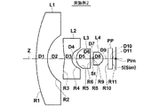
まず、図1を参照しながら、本発明の実施形態にかかる撮像レンズについて説明する。図1は、本発明の実施例1にかかる撮像レンズ1のレンズ断面図である。図1に示す撮像レンズ1は、以下に述べる本発明の第1〜第4の実施形態の構成を備えている。
Embodiment of imaging lens
First, an imaging lens according to an embodiment of the present invention will be described with reference to FIG. FIG. 1 is a lens cross-sectional view of an
図1では、図の左側が物体側、右側が像側であり、無限遠の距離にある物点からの軸上光束2、全画角2ωでの軸外光束3、4も合わせて示してある。図1では、撮像レンズ1が撮像装置に適用される場合を考慮して、撮像レンズ1の像点Pimを含む像面Simに配置された撮像素子5も図示している。撮像素子5は、撮像レンズ1により形成される光学像を電気信号に変換するものであり、例えばCCDイメージセンサやCMOSイメージセンサ等を用いることができる。
In FIG. 1, the left side of the figure is the object side, the right side is the image side, and the axial light beam 2 from an object point at an infinite distance and off-axis light beams 3 and 4 at the full field angle 2ω are also shown. is there. In FIG. 1, the
なお、撮像レンズ1を撮像装置に適用する際には、レンズを装着するカメラ側の構成に応じて、カバーガラスや、ローパスフィルタまたは赤外線カットフィルタ等を設けることが好ましく、図1では、これらを想定した平行平板状の光学部材PPを最も像側のレンズと撮像素子5(像面Sim)の間に配置した例を示している。
When the
まず、本発明の第1の実施形態の構成について説明する。本発明の第1の実施形態にかかる撮像レンズは、物体側から順に、負の第1レンズL1と、負の第2レンズL2と、正の第3レンズL3と、開口絞りStと、正の第4レンズL4とを備える。なお、図1における開口絞りStは、形状や大きさを表すものではなく、光軸Z上の位置を示すものである。 First, the configuration of the first embodiment of the present invention will be described. The imaging lens according to the first embodiment of the present invention includes, in order from the object side, a negative first lens L1, a negative second lens L2, a positive third lens L3, an aperture stop St, and a positive And a fourth lens L4. Note that the aperture stop St in FIG. 1 does not indicate the shape or size, but indicates the position on the optical axis Z.
この撮像レンズは、4枚という少ないレンズ枚数で構成することで、低コスト化とともに光軸方向の全長の小型化を図ることができる。また、物体側に配置された2枚のレンズである第1レンズL1と第2レンズL2を負のレンズとすることで、レンズ系全体を広角化することが容易となる。また、負レンズを2枚にすることで、負レンズに求められる各収差の補正をこれらの2枚のレンズで分担することができ、効果的に補正することができる。同様に、像側の正レンズも第3レンズL3と第4レンズL4の2枚とすることで、像面で像を結ぶための収束作用および正レンズに求められる各収差の補正をこれらの2枚のレンズで分担することができ、効果的に補正することができる。また、開口絞りStを第3レンズL3と第4レンズL4の間に配置することで系全体を小型化することが可能となる。 By configuring the imaging lens with as few as four lenses, the cost can be reduced and the overall length in the optical axis direction can be reduced. In addition, by making the first lens L1 and the second lens L2, which are two lenses disposed on the object side, negative lenses, it becomes easy to widen the entire lens system. Further, by using two negative lenses, correction of each aberration required for the negative lens can be shared by these two lenses, and can be effectively corrected. Similarly, the positive lens on the image side is also composed of two lenses, the third lens L3 and the fourth lens L4, so that the convergence effect for forming an image on the image plane and the correction of each aberration required for the positive lens can be corrected. It can be shared by a single lens and can be corrected effectively. Further, the entire system can be reduced in size by disposing the aperture stop St between the third lens L3 and the fourth lens L4.
また、本発明の第1の実施形態にかかる撮像レンズは、第2レンズL2、第3レンズL3、第4レンズL4の各レンズは少なくとも片側の面が非球面であり、第3レンズL3の材質のd線におけるアッベ数が35以下であり、下記条件式(1)を満足するように構成されている。
−0.2<(R3+R4)/(R3−R4)<0.2 … (1)
ただし、
R3:第2レンズL2の物体側の面の近軸曲率半径
R4:第2レンズL2の像側の面の近軸曲率半径
In the imaging lens according to the first embodiment of the present invention, each of the second lens L2, the third lens L3, and the fourth lens L4 has at least one aspheric surface, and the material of the third lens L3. The Abbe number in the d-line is 35 or less, and the following conditional expression (1) is satisfied.
-0.2 <(R3 + R4) / (R3-R4) <0.2 (1)
However,
R3: Paraxial radius of curvature of the object side surface of the second lens L2 R4: Paraxial radius of curvature of the image side surface of the second lens L2
第2レンズL2、第3レンズL3、第4レンズL4の3枚のレンズを非球面レンズとすることで、少ないレンズ枚数でありながら、諸収差を良好に補正して広角化を図ることができる。 By making the three lenses of the second lens L2, the third lens L3, and the fourth lens L4 an aspherical lens, various aberrations can be corrected well and a wide angle can be achieved while the number of lenses is small. .
第3レンズL3の材質のd線におけるアッベ数を35以下とすることで、倍率の色収差を良好に補正することが可能となる。 By setting the Abbe number of the material of the third lens L3 on the d-line to 35 or less, it is possible to satisfactorily correct lateral chromatic aberration.
条件式(1)を満足することで、第2レンズL2は近軸領域で両凹形状となる。以下、条件式(1)に基づく近軸領域における第2レンズL2の形状について説明する。
まず、上記条件式(1)は下記条件式(1A)のように変形することができる。
−0.2<(1+R4/R3)/(1−R4/R3)<0.2 … (1A)
第2レンズL2の物体側の面が平面、すなわちR3=∞とすると、上記条件式(1A)を満たさないため、第2レンズL2の物体側の面は平面になりえない。
When the conditional expression (1) is satisfied, the second lens L2 has a biconcave shape in the paraxial region. Hereinafter, the shape of the second lens L2 in the paraxial region based on the conditional expression (1) will be described.
First, the conditional expression (1) can be modified as the following conditional expression (1A).
-0.2 <(1 + R4 / R3) / (1-R4 / R3) <0.2 (1A)
If the object side surface of the second lens L2 is a flat surface, that is, R3 = ∞, the above conditional expression (1A) is not satisfied, and therefore the object side surface of the second lens L2 cannot be a flat surface.
同様に、上記条件式(1)は下記条件式(1B)のように変形することができ、
−0.2<(R3/R4+1)/(R3/R4−1)<0.2 … (1B)
第2レンズL2の像側の面を平面、すなわちR4=∞とすると、上記条件式(1B)を満たさないため、第2レンズL2の像側の面は平面になりえない。
Similarly, the conditional expression (1) can be transformed into the following conditional expression (1B),
-0.2 <(R3 / R4 + 1) / (R3 / R4-1) <0.2 (1B)
If the image side surface of the second lens L2 is a plane, that is, R4 = ∞, the conditional expression (1B) is not satisfied, and therefore the image side surface of the second lens L2 cannot be a plane.
次に、第2レンズL2の物体側の面が凸面、すなわちR3>0とすると、第2レンズL2が負レンズであることから、第2レンズL2の像側の面が凸面になることはなく、像側に凹面を向けた負メニスカス形状をなすことになり、R4>0かつR3>R4となる。しかし、そうすると、上記条件式(1A)を満たさなくなるため、第2レンズL2の物体側の面が凸面、すなわちR3>0になることはない。 Next, if the object side surface of the second lens L2 is a convex surface, that is, R3> 0, the second lens L2 is a negative lens, so the image side surface of the second lens L2 will not be a convex surface. , A negative meniscus shape having a concave surface facing the image side, and R4> 0 and R3> R4. However, in this case, the conditional expression (1A) is not satisfied, and the object-side surface of the second lens L2 does not become a convex surface, that is, R3> 0.
よって、第2レンズL2の物体側の面は凹面、すなわちR3<0となる。そこで、R3<0の条件下で、第2レンズL2の像側の面を凸面、すなわちR4<0とすると、第2レンズL2が負レンズであることから、R3>R4の負メニスカス形状をなすことになる。しかし、そうすると、上記条件式(1A)を満たさなくなるため、第2レンズL2が負メニスカス形状になることはない。したがって、R3<0かつR4>0となり、すなわち、第2レンズL2は両凹形状となる。 Therefore, the object side surface of the second lens L2 is concave, that is, R3 <0. Therefore, if the image side surface of the second lens L2 is a convex surface, that is, R4 <0 under the condition of R3 <0, the second lens L2 is a negative lens, so that a negative meniscus shape of R3> R4 is formed. It will be. However, in this case, the conditional expression (1A) is not satisfied, and the second lens L2 does not have a negative meniscus shape. Therefore, R3 <0 and R4> 0, that is, the second lens L2 has a biconcave shape.
このような形状の第2レンズL2の曲率半径を条件式(1)を満足するように選択することで、第2レンズL2の物体側の面と像側の面の曲率半径のバランスをとることができる。また、後述の非球面式で表すように、一般には近軸曲率半径を用いて非球面形状を規定するため、条件式(1)を満足することで、広角化が容易になると共に像面湾曲、ディストーションを良好に補正することが可能となる。条件式(1)の上限以上になると第2レンズL2の物体側の面の曲率半径の絶対値が大きくなり、像面湾曲を良好に補正しながら広角化することが困難となる。また、第2レンズL2のパワーが弱くなり、レンズ系が大型化してしまう。条件式(1)の下限以下になると、第2レンズL2の像側の面の曲率半径の絶対値が大きくなりすぎてしまい、広角化と共にディストーションを良好に補正することが困難となる。 The curvature radius of the object side surface and the image side surface of the second lens L2 is balanced by selecting the curvature radius of the second lens L2 having such a shape so as to satisfy the conditional expression (1). Can do. In addition, as represented by an aspherical expression described later, since the aspherical shape is generally defined using a paraxial radius of curvature, satisfying conditional expression (1) facilitates widening of the angle and curvature of field. It becomes possible to correct distortion well. If the upper limit of conditional expression (1) is exceeded, the absolute value of the radius of curvature of the object-side surface of the second lens L2 increases, making it difficult to widen the angle while favorably correcting curvature of field. Further, the power of the second lens L2 becomes weak, and the lens system becomes large. If the lower limit of conditional expression (1) is not reached, the absolute value of the radius of curvature of the image side surface of the second lens L2 becomes too large, and it becomes difficult to correct distortion well with widening of the angle.
さらに、下記条件式(1−2)を満足することが望ましい。条件式(1−2)の上限を満足することで、広角化と共に像面湾曲をより良好に補正することが可能となる。条件式(1−2)の下限を満足することで、広角化と共にディストーションをより良好に補正することが可能となる。
−0.08<(R3+R4)/(R3−R4)<0.12 … (1−2)
Furthermore, it is desirable that the following conditional expression (1-2) is satisfied. By satisfying the upper limit of the conditional expression (1-2), it becomes possible to correct the field curvature more favorably with widening of the angle. By satisfying the lower limit of the conditional expression (1-2), it becomes possible to correct distortion more favorably with widening of the angle.
-0.08 <(R3 + R4) / (R3-R4) <0.12 (1-2)
さらに、下記条件式(1−3)を満足することがより望ましい。条件式(1−3)の上限を満足することで、広角化と共に像面湾曲をさらに良好に補正することが可能となる。
−0.08<(R3+R4)/(R3−R4)<0.08 … (1−3)
Furthermore, it is more desirable to satisfy the following conditional expression (1-3). By satisfying the upper limit of the conditional expression (1-3), it becomes possible to correct the field curvature more satisfactorily together with the wide angle.
-0.08 <(R3 + R4) / (R3-R4) <0.08 (1-3)
またさらに、下記条件式(1−4)を満足することがより望ましい。条件式(1−4)の上限を満足することで、広角化と共に像面湾曲をさらにより良好に補正することが可能となる。条件式(1−4)の下限を満足することで、広角化と共にディストーションをさらにより良好に補正することが可能となる。
−0.06<(R3+R4)/(R3−R4)<0.03 … (1−4)
Furthermore, it is more desirable to satisfy the following conditional expression (1-4). By satisfying the upper limit of the conditional expression (1-4), it becomes possible to correct the field curvature further better together with the wide angle. By satisfying the lower limit of the conditional expression (1-4), it becomes possible to correct the distortion even better together with the widening of the angle.
-0.06 <(R3 + R4) / (R3-R4) <0.03 (1-4)
次に、本発明の第2の実施形態の構成について説明する。本発明の第2の実施形態にかかる撮像レンズは、物体側から順に、像側に凹面を向けたメニスカス形状の負の第1レンズL1と、物体側の面および像側の面が非球面である第2レンズL2と、少なくとも物体側の面が非球面である正の第3レンズL3と、開口絞りStと、少なくとも像側の面が非球面である正の第4レンズL4とを備える。 Next, the configuration of the second exemplary embodiment of the present invention will be described. The imaging lens according to the second embodiment of the present invention includes, in order from the object side, a meniscus negative first lens L1 with a concave surface facing the image side, and the object side surface and the image side surface are aspherical surfaces. It includes a certain second lens L2, a positive third lens L3 whose surface on the object side is aspherical, an aperture stop St, and a positive fourth lens L4 whose surface on the image side is aspherical.
この撮像レンズは、4枚という少ないレンズ枚数で構成することで、低コスト化とともに光軸方向の全長の小型化を図ることができる。また、開口絞りStを第3レンズL3と第4レンズL4の間に配置することで系全体を小型化することが可能となる。そして、最も物体側に配置される第1レンズL1を像側に凹面を向けた負メニスカスレンズとすることで、レンズ系全体を広角化することが可能となり、例えば全画角が180°を超えるような広角のレンズを作製することが可能となる。 By configuring the imaging lens with as few as four lenses, the cost can be reduced and the overall length in the optical axis direction can be reduced. Further, the entire system can be reduced in size by disposing the aperture stop St between the third lens L3 and the fourth lens L4. By making the first lens L1 arranged closest to the object side into a negative meniscus lens having a concave surface facing the image side, the entire lens system can be widened. For example, the total angle of view exceeds 180 °. Such a wide-angle lens can be manufactured.
本発明の第2の実施形態の撮像レンズでは、第2レンズL2の物体側の面および像側の面、第3レンズL3の物体側の面、第4レンズL4の像側の面を非球面としている。すなわち、これら3つのレンズのうち、開口絞りStに最も遠い第2レンズL2は両側の面が非球面となっており、開口絞りStに隣接して配置された第3レンズL3、第4レンズL4については、それぞれ開口絞りStに遠い方の面が必ず非球面となっている。図1に示すように、このように、各像高の軸外光線と軸上光線がより分離されている面を非球面とすることで、諸収差を効果的に補正することができ、少ないレンズ枚数でありながら、広角化と同時に像面湾曲とディストーションを良好に補正することに有利となる。 In the imaging lens of the second embodiment of the present invention, the object side surface and the image side surface of the second lens L2, the object side surface of the third lens L3, and the image side surface of the fourth lens L4 are aspherical surfaces. It is said. That is, among these three lenses, the second lens L2 farthest from the aperture stop St has aspheric surfaces on both sides, and the third lens L3 and the fourth lens L4 arranged adjacent to the aperture stop St. As for, the surface far from the aperture stop St is always an aspherical surface. As shown in FIG. 1, various aberrations can be effectively corrected by making the surface on which the off-axis ray and the on-axis ray at each image height are separated more aspherical as described above. Although it is the number of lenses, it is advantageous to correct the field curvature and distortion well at the same time as widening the angle.
また、本発明の第2の実施形態にかかる撮像レンズは、第3レンズL3の材質のd線におけるアッベ数が35以下であり、下記条件式(2)を満足するように構成されている。
1.0<D3/f<5.0 … (2)
ただし、
D3:第2レンズL2の中心厚
f:全系の焦点距離
In addition, the imaging lens according to the second embodiment of the present invention is configured such that the Abbe number of the material of the third lens L3 on the d-line is 35 or less and the following conditional expression (2) is satisfied.
1.0 <D3 / f <5.0 (2)
However,
D3: Center thickness of the second lens L2 f: Focal length of the entire system
第3レンズL3の材質のd線におけるアッベ数を35以下とすることで、倍率の色収差を良好に補正することが可能となる。 By setting the Abbe number of the material of the third lens L3 on the d-line to 35 or less, it is possible to satisfactorily correct lateral chromatic aberration.
条件式(2)の上限以上になるとレンズ系が大型化してしまう。条件式(2)の下限以下になると、第2レンズL2の中心厚が小さくなってしまい、第2レンズL2の周辺部と中心部の肉厚比が大きくなり、成形が困難となる。
本発明の第2の実施形態の撮像レンズによれば、4枚のレンズ系において、第2レンズL2から第4レンズL4の各レンズに効果的に非球面を設け、各レンズの面形状とパワー、絞りの位置、第3レンズL3の材質等の構成を好適に設定し、条件式(2)を満足するようにしているため、小型に構成可能で、全画角が180度を超えるような広角化を達成できるとともに、像面湾曲、ディストーション、倍率の色収差を良好に補正して結像領域周辺部まで良好な像を得ることができる高い光学性能を有する撮像レンズを実現することができる。なお、本発明の第2の実施形態の撮像レンズの第1レンズL1の「凹面」、「メニスカス形状」は、非球面については近軸領域で考えるものとする。
If the upper limit of conditional expression (2) is exceeded, the lens system becomes large. When the lower limit of conditional expression (2) is not reached, the center thickness of the second lens L2 becomes small, the thickness ratio between the peripheral portion and the center portion of the second lens L2 becomes large, and molding becomes difficult.
According to the imaging lens of the second embodiment of the present invention, in the four lens system, each lens from the second lens L2 to the fourth lens L4 is effectively provided with an aspherical surface, and the surface shape and power of each lens. The configuration of the aperture position, the material of the third lens L3, etc. is suitably set so as to satisfy the conditional expression (2), so that it can be made compact and the total angle of view exceeds 180 degrees. It is possible to realize an imaging lens having high optical performance that can achieve a wide angle and correct a curvature of field, distortion, and chromatic aberration of magnification well to obtain a good image up to the periphery of the imaging region. The “concave surface” and “meniscus shape” of the first lens L1 of the imaging lens according to the second embodiment of the present invention are considered in the paraxial region for an aspheric surface.
さらに、下記条件式(2−2)を満足することが望ましい。条件式(2−2)の上限を満足すると、レンズ系の小型化がより容易となる。
1.0<D3/f<2.2 … (2−2)
Furthermore, it is desirable that the following conditional expression (2-2) is satisfied. When the upper limit of conditional expression (2-2) is satisfied, the lens system can be more easily downsized.
1.0 <D3 / f <2.2 (2-2)
次に、本発明の第3の実施形態の構成について説明する。本発明の第3の実施形態にかかる撮像レンズは、物体側から順に、負の第1レンズL1と、負の第2レンズL2と、正の第3レンズL3と、開口絞りStと、正の第4レンズL4とを備える。 Next, the configuration of the third exemplary embodiment of the present invention will be described. An imaging lens according to the third embodiment of the present invention includes, in order from the object side, a negative first lens L1, a negative second lens L2, a positive third lens L3, an aperture stop St, and a positive And a fourth lens L4.
この撮像レンズは、4枚という少ないレンズ枚数で構成することで、低コスト化とともに光軸方向の全長の小型化を図ることができる。また、物体側に配置された2枚のレンズである第1レンズL1と第2レンズL2を負のレンズとすることで、レンズ系全体を広角化することが容易となる。また、負レンズを2枚にすることで、負レンズに求められる各収差の補正をこれらの2枚のレンズで分担することができ、効果的に補正することができる。同様に、像側の正レンズも第3レンズL3と第4レンズL4の2枚とすることで、像面で像を結ぶための収束作用および正レンズに求められる各収差の補正をこれらの2枚のレンズで分担することができ、効果的に補正することができる。また、開口絞りStを第3レンズL3と第4レンズL4の間に配置することで系全体を小型化することが可能となる。 By configuring the imaging lens with as few as four lenses, the cost can be reduced and the overall length in the optical axis direction can be reduced. In addition, by making the first lens L1 and the second lens L2, which are two lenses disposed on the object side, negative lenses, it becomes easy to widen the entire lens system. Further, by using two negative lenses, correction of each aberration required for the negative lens can be shared by these two lenses, and can be effectively corrected. Similarly, the positive lens on the image side is also composed of two lenses, the third lens L3 and the fourth lens L4, so that the convergence effect for forming an image on the image plane and the correction of each aberration required for the positive lens can be corrected. It can be shared by a single lens and can be corrected effectively. Further, the entire system can be reduced in size by disposing the aperture stop St between the third lens L3 and the fourth lens L4.
また、本発明の第3の実施形態にかかる撮像レンズは、第1レンズL1の中心厚が1.7mm以上であり、下記条件式(3)を満足するように構成されている。
2.5<D1/f<5.5 … (3)
ただし、
D1:第1レンズL1の中心厚
f:全系の焦点距離
The imaging lens according to the third embodiment of the present invention is configured so that the center thickness of the first lens L1 is 1.7 mm or more and satisfies the following conditional expression (3).
2.5 <D1 / f <5.5 (3)
However,
D1: Center thickness of the first lens L1 f: Focal length of the entire system
例えば車載等の用途で用いられる場合、最も物体側に配置される第1レンズL1には各種衝撃に対する強度が求められるため、第1レンズL1の中心厚が1.7mm以上であることが好ましく、条件式(3)を満足することが好ましい。条件式(3)の下限以下になると、第1レンズL1が薄くなり割れやすくなる。条件式(3)の上限以上になるとレンズ系が大型化してしまう。あるいは、第1レンズL1の大型化を避けるためには、第1レンズL1の物体側の面の曲率半径の絶対値を大きくして周辺光線を急激に曲げる必要があるが、第1レンズL1の物体側の面の曲率半径の絶対値を大きくして周辺光線を急激に曲げると特に周辺部でディストーションが大きくなってしまう。ディストーションが大きくなると画像周辺部が像面Sim上で小さく結像してしまうため、撮像素子で撮像して画像処理により拡大しても中心と比べて画質が低下してしまうという問題がある。
本発明の第3の実施形態の撮像レンズによれば、4枚のレンズ系において、全系におけるパワー配置、絞りの位置、第1レンズL1の中心厚の構成を好適に設定し、条件式(3)を満足するようにしているため、小型に構成可能で、全画角が180度を超えるような広角化を達成できるとともに、ディストーションを良好に補正して結像領域周辺部まで良好な像を得ることができる高い光学性能を有する撮像レンズを実現することができる。
For example, when used in applications such as in-vehicle, the first lens L1 arranged closest to the object side is required to have strength against various impacts, and therefore the center thickness of the first lens L1 is preferably 1.7 mm or more. It is preferable to satisfy conditional expression (3). If the lower limit of conditional expression (3) is not reached, the first lens L1 becomes thin and easily cracked. If the upper limit of conditional expression (3) is exceeded, the lens system becomes large. Alternatively, in order to avoid an increase in the size of the first lens L1, it is necessary to increase the absolute value of the radius of curvature of the object-side surface of the first lens L1 and bend the peripheral rays rapidly. If the absolute value of the radius of curvature of the object side surface is increased and the peripheral rays are bent sharply, the distortion will increase particularly in the peripheral portion. When the distortion becomes large, the image peripheral part forms a small image on the image plane Sim, so that there is a problem that the image quality is deteriorated compared to the center even if the image is picked up by the image pickup element and enlarged by image processing.
According to the imaging lens of the third embodiment of the present invention, in the four lens systems, the configuration of the power arrangement in the entire system, the position of the diaphragm, and the center thickness of the first lens L1 are suitably set, and the conditional expression ( Since 3) is satisfied, it can be configured in a small size, can achieve a wide angle with a total angle of view exceeding 180 degrees, and corrects distortion well to provide a good image up to the periphery of the imaging region. An imaging lens having high optical performance capable of obtaining the above can be realized.
さらに、下記条件式(3−2)を満足することが望ましい。条件式(3−2)の上限を満足することで、レンズ系を小型化することが容易となる。条件式(3−2)の下限を満足することで、第1レンズL1をより割れにくくすることが可能となる。
2.5<D1/f<3.0 … (3−2)
Furthermore, it is desirable to satisfy the following conditional expression (3-2). By satisfying the upper limit of conditional expression (3-2), it is easy to reduce the size of the lens system. By satisfying the lower limit of conditional expression (3-2), the first lens L1 can be made more difficult to break.
2.5 <D1 / f <3.0 (3-2)
次に、本発明の第4の実施形態の構成について説明する。本発明の第4の実施形態にかかる撮像レンズは、物体側から順に、負の第1レンズL1と、負の第2レンズL2と、正の第3レンズL3と、開口絞りStと、正の第4レンズL4とを備える。 Next, the structure of the 4th Embodiment of this invention is demonstrated. An imaging lens according to the fourth embodiment of the present invention includes, in order from the object side, a negative first lens L1, a negative second lens L2, a positive third lens L3, an aperture stop St, and a positive And a fourth lens L4.
この撮像レンズは、4枚という少ないレンズ枚数で構成することで、低コスト化とともに光軸方向の全長の小型化を図ることができる。また、物体側に配置された2枚のレンズである第1レンズL1と第2レンズL2を負のレンズとすることで、レンズ系全体を広角化することが容易となる。また、負レンズを2枚にすることで、負レンズに求められる各収差の補正をこれらの2枚のレンズで分担することができ、効果的に補正することができる。同様に、像側の正レンズも第3レンズL3と第4レンズL4の2枚とすることで、像面で像を結ぶための収束作用および正レンズに求められる各収差の補正をこれらの2枚のレンズで分担することができ、効果的に補正することができる。また、開口絞りStを第3レンズL3と第4レンズL4の間に配置することで系全体を小型化することが可能となる。 By configuring the imaging lens with as few as four lenses, the cost can be reduced and the overall length in the optical axis direction can be reduced. In addition, by making the first lens L1 and the second lens L2, which are two lenses disposed on the object side, negative lenses, it becomes easy to widen the entire lens system. Further, by using two negative lenses, correction of each aberration required for the negative lens can be shared by these two lenses, and can be effectively corrected. Similarly, the positive lens on the image side is also composed of two lenses, the third lens L3 and the fourth lens L4, so that the convergence effect for forming an image on the image plane and the correction of each aberration required for the positive lens can be corrected. It can be shared by a single lens and can be corrected effectively. Further, the entire system can be reduced in size by disposing the aperture stop St between the third lens L3 and the fourth lens L4.
また、本発明の第4の実施形態にかかる撮像レンズは、第1レンズL1の中心厚が1.7mm以上であり、下記条件式(4)を満足するように構成されている。
0.5<ED1/R1<0.95 … (4)
ただし、
ED1:第1レンズL1の物体側の面の有効径(直径)
R1:第1レンズL1の物体側の面の曲率半径
The imaging lens according to the fourth embodiment of the present invention is configured so that the center thickness of the first lens L1 is 1.7 mm or more and satisfies the following conditional expression (4).
0.5 <ED1 / R1 <0.95 (4)
However,
ED1: Effective diameter (diameter) of the object side surface of the first lens L1
R1: radius of curvature of the object side surface of the first lens L1
条件式(4)の上限以上になると、第1レンズL1の物体側の面が半球に近くなり、加工が困難となるか、コストアップの原因となってしまう。あるいは、第1レンズL1が大きくなってしまい、車の外観を損ねてしまうという問題もある。条件式(4)の下限以下になると、加工は容易だが、ディストーションの補正が困難となり、周辺部の画像が像面Sim上で小さく結像されてしまうため、撮像素子で撮像して画像処理により拡大しても中心と比べて画質が低下してしまうという問題がある。
本発明の第4の実施形態の撮像レンズによれば、4枚のレンズ系において、全系におけるパワー配置、絞りの位置、第1レンズL1の中心厚の構成を好適に設定し、条件式(4)を満足するようにしているため、小型に構成可能で、全画角が180度を超えるような広角化を達成できるとともに、ディストーションを良好に補正して結像領域周辺部まで良好な像を得ることができる高い光学性能を有する撮像レンズを実現することができる。本発明の第4の実施形態の撮像レンズのR1は第1レンズL1の物体側の面が非球面の場合は近軸曲率半径を用いることにする。
If the upper limit of conditional expression (4) is exceeded, the object side surface of the first lens L1 becomes close to a hemisphere, which makes processing difficult or causes an increase in cost. Or there also exists a problem that the 1st lens L1 will become large and the external appearance of a vehicle will be impaired. If the lower limit of conditional expression (4) is not reached, processing is easy, but distortion correction becomes difficult, and the peripheral image is formed small on the image plane Sim. There is a problem that even if the image is enlarged, the image quality is deteriorated as compared with the center.
According to the imaging lens of the fourth embodiment of the present invention, in the four lens systems, the configuration of the power arrangement, the position of the diaphragm, and the center thickness of the first lens L1 in the entire system is suitably set, and the conditional expression ( Since 4) is satisfied, it can be configured in a small size, can achieve a wide angle with a total angle of view exceeding 180 degrees, and corrects distortion well to provide a good image up to the periphery of the imaging region. An imaging lens having high optical performance capable of obtaining the above can be realized. The R1 of the imaging lens according to the fourth embodiment of the present invention uses a paraxial radius of curvature when the object side surface of the first lens L1 is an aspherical surface.
上記第1〜第4の実施形態にかかる撮像レンズは、他の実施形態の構成の少なくとも1つ、または他の実施形態における好ましい構成の少なくとも1つを有するものであってもよい。例えば、第1の実施形態にかかる撮像レンズが、第2の実施形態の構成を有するものであってもよく、第2の実施形態にかかる撮像レンズが第1の実施形態の構成において述べた好ましい構成を有するものであってもよい。 The imaging lens according to the first to fourth embodiments may have at least one of the configurations of the other embodiments, or at least one of the preferable configurations of the other embodiments. For example, the imaging lens according to the first embodiment may have the configuration of the second embodiment, and the imaging lens according to the second embodiment is preferably described in the configuration of the first embodiment. It may have a configuration.
次に、本発明の上記第1〜第4の実施形態にかかる撮像レンズが有することが好ましい構成を挙げて、その作用効果について述べる。なお、好ましい態様としては、以下のいずれか1つの構成を有するものでもよく、あるいは任意の2つ以上を組合せた構成を有するものでもよい。 Next, the function and effect of the imaging lens according to the first to fourth embodiments of the present invention will be described. In addition, as a preferable aspect, it may have any one of the following configurations, or may have a configuration in which any two or more are combined.
下記条件式(5)を満足することが望ましい。
2.0<D2/f<5.0 … (5)
ただし、
f:全系の焦点距離
D2:第1レンズL1と第2レンズL2の光軸上の空気間隔
It is desirable to satisfy the following conditional expression (5).
2.0 <D2 / f <5.0 (5)
However,
f: focal length of entire system D2: air spacing on the optical axis of the first lens L1 and the second lens L2
条件式(5)の上限以上になるとレンズ系が大型化してしまう。条件式(5)の下限以下になると、第1レンズL1と第2レンズL2の間隔が小さくなってしまい、第2レンズL2の物体側の面の非球面形状が制限され、像面湾曲、ディストーションの補正が困難となる。 If the upper limit of conditional expression (5) is exceeded, the lens system becomes large. If the lower limit of conditional expression (5) is not reached, the distance between the first lens L1 and the second lens L2 becomes small, the aspherical shape of the object-side surface of the second lens L2 is limited, and field curvature and distortion are limited. Correction becomes difficult.
さらに、下記条件式(5−2)を満足することが望ましい。条件式(5−2)の上限を満足すると、レンズ系の小型化がより容易となる。条件式(5−2)の下限を満足すると、像面湾曲、ディストーションの補正がより容易となる。
2.3<D2/f<4.5… (5−2)
Furthermore, it is desirable that the following conditional expression (5-2) is satisfied. When the upper limit of conditional expression (5-2) is satisfied, the lens system can be more easily downsized. When the lower limit of conditional expression (5-2) is satisfied, correction of field curvature and distortion becomes easier.
2.3 <D2 / f <4.5 (5-2)
下記条件式(6)を満足することが望ましい。
0.01<|f12/f34|<0.5 … (6)
ただし、
f12:第1レンズL1と第2レンズL2の合成焦点距離
f34:第3レンズL3と第4レンズL4の合成焦点距離
It is desirable to satisfy the following conditional expression (6).
0.01 <| f12 / f34 | <0.5 (6)
However,
f12: Composite focal length of the first lens L1 and the second lens L2 f34: Composite focal length of the third lens L3 and the fourth lens L4
条件式(6)の上限以上になると広角化が難しくなると同時に像面湾曲が大きくなり、良好な像を得ることが難しくなる。条件式(6)の下限以下になると広角化は容易に達成できるが、コマ収差が増大してしまい、画角の周辺においても良好な像を得ることが困難となる。 If the upper limit of conditional expression (6) is exceeded, it will be difficult to widen the angle, and the curvature of field will increase, making it difficult to obtain a good image. If the lower limit of conditional expression (6) is reached, widening of the angle can be easily achieved, but coma increases and it becomes difficult to obtain a good image even in the vicinity of the angle of view.
下記条件式(7)を満足することが望ましい。
2.5<(D4+D5)/f<5.5 … (7)
ただし、
f:全系の焦点距離
D4:第2レンズL2と第3レンズL3の光軸上の空気間隔
D5:第3レンズL3の中心厚
It is desirable to satisfy the following conditional expression (7).
2.5 <(D4 + D5) / f <5.5 (7)
However,
f: focal length of entire system D4: air distance on optical axis of second lens L2 and third lens L3 D5: center thickness of third lens L3
条件式(7)を満足することで、球面収差、ディストーション、コマ収差の良好な補正が可能になり、さらにバックフォーカスが長くとれ、画角を大きくすることができ、十分な性能が得られる。条件式(7)の上限以上になると、球面収差、ディストーション、コマ収差を良好に補正することが困難になり、長いバックフォーカスや大きな画角を確保することが困難になる。また、条件式(7)の上限以上になると、最も物体側の負の第1レンズL1の径が大きくなり、かつレンズ全長も長くなり、小型化が難しくなる。条件式(7)の下限以下になると球面収差、コマ収差を良好に補正できなくなり、Fナンバーの小さなレンズ系を得るのが困難になる。 Satisfying conditional expression (7) makes it possible to correct spherical aberration, distortion, and coma aberration, further increase the back focus, increase the angle of view, and obtain sufficient performance. If the upper limit of conditional expression (7) is exceeded, it will be difficult to satisfactorily correct spherical aberration, distortion, and coma, and it will be difficult to ensure a long back focus and a large angle of view. On the other hand, if the upper limit of conditional expression (7) is exceeded, the diameter of the most negative first lens L1 on the object side becomes large, and the total lens length becomes long, making it difficult to reduce the size. If the lower limit of conditional expression (7) is not reached, spherical aberration and coma cannot be corrected well, and it becomes difficult to obtain a lens system having a small F number.
さらに、下記条件式(7−2)を満足することが望ましい。条件式(7−2)の上限を満足することで球面収差、ディストーション、コマ収差をさらに良好に補正でき、所望の長さのバックフォーカス、大きな画角の確保がより容易となる。条件式(7−2)の下限を満足すると、球面収差、コマ収差の補正が容易となる。
3.0<(D4+D5)/f<4.0 … (7−2)
Furthermore, it is desirable to satisfy the following conditional expression (7-2). By satisfying the upper limit of conditional expression (7-2), spherical aberration, distortion, and coma aberration can be corrected more satisfactorily, and it becomes easier to secure a desired back focal length and a large angle of view. When the lower limit of conditional expression (7-2) is satisfied, correction of spherical aberration and coma becomes easy.
3.0 <(D4 + D5) / f <4.0 (7-2)
下記条件式(8)を満足することが望ましい。なお、Lの算出の際には、バックフォーカス分は空気換算長とする。すなわち、最も像側のレンズと像面Simとの間にカバーガラスやフィルタなどがある場合は、カバーガラスやフィルタの厚さは空気換算した値を用いるものとする。
10.0<L/f<20.0 … (8)
ただし、
f:全系の焦点距離
L:第1レンズL1の物体側の面から像面までの光軸上の距離
It is desirable to satisfy the following conditional expression (8). Note that when calculating L, the back focus is the air equivalent length. That is, when there is a cover glass or a filter between the lens closest to the image side and the image plane Sim, the thickness of the cover glass or filter is an air-converted value.
10.0 <L / f <20.0 (8)
However,
f: Focal length L of the entire system L: Distance on the optical axis from the object side surface of the first lens L1 to the image plane
条件式(8)を満足することで、小型化と同時に広角化を達成することが可能となる。条件式(8)の上限以上になると広角化は容易に達成できるがレンズ系が大型化してしまう。条件式(8)の下限以下になるとレンズ系は小型化することができるが、広角化を達成することが困難となる。 By satisfying conditional expression (8), it is possible to achieve a wide angle as well as a reduction in size. If the upper limit of conditional expression (8) is exceeded, widening can be easily achieved, but the lens system becomes large. If the lower limit of conditional expression (8) is not reached, the lens system can be miniaturized, but it is difficult to achieve a wide angle.
さらに、下記条件式(8−2)を満足することが望ましい。条件式(8−2)の上限を満足すると、小型化がより容易となる。条件式(8−2)の下限を満足すると、広角化がより容易となる。
13.0<L/f<19.0 … (8−2)
Furthermore, it is desirable to satisfy the following conditional expression (8-2). If the upper limit of the conditional expression (8-2) is satisfied, downsizing becomes easier. When the lower limit of conditional expression (8-2) is satisfied, widening of the angle becomes easier.
13.0 <L / f <19.0 (8-2)
レンズ系を小型にするためには、第1レンズL1の物体側の面から像面までの光軸上の距離Lを15mm以下とすることが望ましく、さらにレンズ系を小型にするためには、上記Lを13mm以下とすることが望ましい。 In order to reduce the size of the lens system, it is desirable that the distance L on the optical axis from the object-side surface of the first lens L1 to the image plane is 15 mm or less, and in order to further reduce the size of the lens system, The L is preferably 13 mm or less.
下記条件式(9)を満足することが望ましい。なお、Bfはバックフォーカスに相当するものであり、その算出の際には空気換算長を用いるものとする。すなわち、最も像側のレンズと像面Simとの間にカバーガラスやフィルタなどがある場合は、空気換算した値を用いるものとする。
1.5<Bf/f<4.0 … (9)
ただし、
f:全系の焦点距離
Bf:第4レンズL4の像側の面から像面までの光軸上の距離
It is desirable to satisfy the following conditional expression (9). Bf corresponds to the back focus, and the air conversion length is used for the calculation. That is, when there is a cover glass or a filter between the lens closest to the image side and the image plane Sim, a value converted into air is used.
1.5 <Bf / f <4.0 (9)
However,
f: focal length of entire system Bf: distance on the optical axis from the image side surface of the fourth lens L4 to the image surface
条件式(9)の上限以上になるとレンズ系が大型化してしまう。条件式(9)の下限以下になるとレンズ系と撮像素子との間に各種フィルタやカバーガラスなどを挿入することが困難となる。 If the upper limit of conditional expression (9) is exceeded, the lens system becomes large. If the lower limit of conditional expression (9) is not reached, it is difficult to insert various filters, cover glasses, etc. between the lens system and the image sensor.
さらに、下記条件式(9−2)を満足することが望ましい。条件式(9−2)の上限を満足すると、小型化がより容易となる。条件式(9−2)の下限を満足すると、バックフォーカスの確保が容易となる。
2.0<Bf/f<3.5 … (9−2)
Furthermore, it is desirable to satisfy the following conditional expression (9-2). When the upper limit of conditional expression (9-2) is satisfied, the size can be reduced more easily. When the lower limit of conditional expression (9-2) is satisfied, it is easy to secure the back focus.
2.0 <Bf / f <3.5 (9-2)
下記条件式(10)を満足することが望ましい。
0.3<(R8−R9)/(R8+R9)<1.0 … (10)
ただし、
R8:第4レンズL4の物体側の面の近軸曲率半径
R9:第4レンズL4の像側の面の近軸曲率半径
It is desirable to satisfy the following conditional expression (10).
0.3 <(R8−R9) / (R8 + R9) <1.0 (10)
However,
R8: Paraxial radius of curvature of the object side surface of the fourth lens L4 R9: Paraxial radius of curvature of the image side surface of the fourth lens L4
上記条件式(10)を満足することで、第4レンズL4は近軸領域でメニスカス形状となる。以下、条件式(10)に基づく近軸領域における第4レンズL4の形状について説明する。
まず、上記条件式(10)は下記条件式(10A)のように変形できる。
0.3<(1−R9/R8)/(1+R9/R8)<1.0 … (10A)
第4レンズL4の物体側の面が平面、すなわちR8=∞とすると、上記条件式(10A)を満たさないため、第4レンズL4の物体側の面は平面になりえない。
When the conditional expression (10) is satisfied, the fourth lens L4 has a meniscus shape in the paraxial region. Hereinafter, the shape of the fourth lens L4 in the paraxial region based on the conditional expression (10) will be described.
First, the conditional expression (10) can be transformed into the following conditional expression (10A).
0.3 <(1-R9 / R8) / (1 + R9 / R8) <1.0 (10A)
If the object side surface of the fourth lens L4 is a flat surface, that is, R8 = ∞, the above conditional expression (10A) is not satisfied, and therefore the object side surface of the fourth lens L4 cannot be a flat surface.
同様に、上記条件式(10)は下記条件式(10B)のように変形することができ、
0.3<(R8/R9−1)/(R8/R9+1)<1.0 … (10B)
第4レンズL4の像側の面を平面、すなわちR9=∞とすると、上記条件式(10B)を満たさないため、第4レンズL4の像側の面は平面になりえない。
Similarly, the conditional expression (10) can be transformed into the following conditional expression (10B),
0.3 <(R8 / R9-1) / (R8 / R9 + 1) <1.0 (10B)
When the image side surface of the fourth lens L4 is a flat surface, that is, R9 = ∞, the conditional expression (10B) is not satisfied, and therefore the image side surface of the fourth lens L4 cannot be a flat surface.
次に、第4レンズL4の物体側の面と像側の面がともに凸面、すなわちR8>0かつR9<0とすると、条件式(10A)の(1−R9/R8)が1より大きくなり、(1+R9/R8)が1より小さくなり、条件式(10A)の上限を満たさなくなるため、第4レンズL4が両凸形状、すなわちR8>0かつR9<0になることはない。 Next, if both the object side surface and the image side surface of the fourth lens L4 are convex surfaces, that is, R8> 0 and R9 <0, then (1-R9 / R8) in the conditional expression (10A) becomes larger than 1. , (1 + R9 / R8) becomes smaller than 1 and does not satisfy the upper limit of the conditional expression (10A), the fourth lens L4 is not biconvex, that is, R8> 0 and R9 <0.
第4レンズL4の物体側の面が凸面で、第4レンズL4の像側の面が凹面、すなわち、R8>0かつR9>0とすると、第4レンズL4が正レンズであることから、R8<R9となる。しかし、そうすると、上記条件式(10A)の(1−R9/R8)が負となり、(1+R9/R8)は正であるから、上記条件式(10A)を満たさなくなるため、第4レンズL4の物体側の面が凸面、すなわちR8>0になることはない。 When the object side surface of the fourth lens L4 is a convex surface and the image side surface of the fourth lens L4 is a concave surface, that is, when R8> 0 and R9> 0, the fourth lens L4 is a positive lens. <R9. However, in this case, since (1−R9 / R8) in the conditional expression (10A) is negative and (1 + R9 / R8) is positive, the conditional expression (10A) is not satisfied, so the object of the fourth lens L4 The side surface is not convex, that is, R8> 0.
よって、第4レンズL4の物体側の面は凹面、すなわちR8<0となる。さらに、第4レンズL4が正レンズであること、上述したように第4レンズL4の像側の面が平面になりえないことを考慮すると、第4レンズL4は正メニスカス形状となる。 Therefore, the object side surface of the fourth lens L4 is concave, that is, R8 <0. Further, considering that the fourth lens L4 is a positive lens and that the image side surface of the fourth lens L4 cannot be a flat surface as described above, the fourth lens L4 has a positive meniscus shape.
以上のように、上記条件式(10)を満足することで、第4レンズL4を近軸領域においてメニスカス形状にすることができ、テレセントリック性の良いレンズを作製することが可能となると共に、像面湾曲と球面収差を良好に補正することが可能となる。すなわち、条件式(10)の上限を満足することで、像面湾曲と球面収差を良好に補正することが可能となる。また、条件式(10)の下限を満足することで、第4レンズL4の像側の面の曲率半径の絶対値が大きくなりすぎるか第4レンズL4の物体側の面の曲率半径の絶対値が小さくなりすぎて第4レンズL4のパワーが小さくなりすぎるのを抑制できる。これにより、結像領域周辺での光線が像面(撮像素子)に入射する角度が大きくなってテレセントリック性が悪化するのを抑制できるため、いわゆるテレセントリック性の良いレンズ系を作製することが可能になる。 As described above, when the conditional expression (10) is satisfied, the fourth lens L4 can be formed in a meniscus shape in the paraxial region, and a lens having excellent telecentricity can be manufactured. It is possible to satisfactorily correct the surface curvature and spherical aberration. That is, by satisfying the upper limit of conditional expression (10), it is possible to satisfactorily correct field curvature and spherical aberration. Further, by satisfying the lower limit of conditional expression (10), the absolute value of the radius of curvature of the image side surface of the fourth lens L4 becomes too large, or the absolute value of the radius of curvature of the object side surface of the fourth lens L4. Can be prevented from becoming too small and the power of the fourth lens L4 becoming too small. As a result, it is possible to suppress the deterioration of telecentricity due to an increase in the angle at which light rays in the periphery of the imaging region enter the image plane (imaging device), so that it is possible to manufacture a lens system with good so-called telecentricity. Become.
さらに、下記条件式(10−2)を満足することが望ましい。条件式(10−2)の上限を満足することで、像面湾曲と球面収差をさらに良好に補正することが可能となる。条件式(10−2)の下限を満足することで、さらにテレセントリック性の良いレンズを作製することが可能となる。
0.4<(R8−R9)/(R8+R9)<0.9 … (10−2)
Furthermore, it is desirable to satisfy the following conditional expression (10-2). By satisfying the upper limit of conditional expression (10-2), it becomes possible to correct field curvature and spherical aberration more satisfactorily. By satisfying the lower limit of the conditional expression (10-2), it becomes possible to manufacture a lens with better telecentricity.
0.4 <(R8−R9) / (R8 + R9) <0.9 (10-2)
下記条件式(11)を満足することが望ましい。
−13<R8/f<−3 … (11)
ただし、
f:全系の焦点距離
R8:第4レンズL4の物体側の面の近軸曲率半径
It is desirable to satisfy the following conditional expression (11).
−13 <R8 / f <−3 (11)
However,
f: focal length of entire system R8: paraxial radius of curvature of object side surface of fourth lens L4
条件式(11)の上限以上になると第4レンズL4のパワーが弱くなり、結像領域周辺での光線が像面(撮像素子)に入射する角度を抑えることが困難となり、いわゆるテレセントリック性の良いレンズを作製することが困難となる。条件式(11)の下限以下になると球面収差の補正が困難となる。 When the upper limit of the conditional expression (11) is exceeded, the power of the fourth lens L4 becomes weak, and it becomes difficult to suppress the angle at which the light rays around the imaging region enter the image plane (imaging device), and so-called telecentricity is good. It becomes difficult to produce a lens. If the lower limit of conditional expression (11) is not reached, it is difficult to correct spherical aberration.
さらに、下記条件式(11−2)を満足することが望ましい。条件式(11−2)の上限を満足することで、テレセントリック性の良いレンズを作製することがより容易となる。条件式(11−2)の下限を満足すると、球面収差の補正がより容易となる。
−11.5<R8/f<−4 … (11−2)
Furthermore, it is desirable to satisfy the following conditional expression (11-2). By satisfying the upper limit of conditional expression (11-2), it becomes easier to manufacture a lens with good telecentricity. When the lower limit of conditional expression (11-2) is satisfied, spherical aberration can be corrected more easily.
−11.5 <R8 / f <−4 (11-2)
下記条件式(12)を満足することが望ましい。
3.2<L/f34<6.0 … (12)
ただし、
L:第1レンズL1の物体側の面から像面までの光軸上の距離
f34:第3レンズL3と第4レンズL4の合成焦点距離
It is desirable that the following conditional expression (12) is satisfied.
3.2 <L / f34 <6.0 (12)
However,
L: Distance on the optical axis from the object side surface of the first lens L1 to the image plane f34: Composite focal length of the third lens L3 and the fourth lens L4
条件式(12)の上限以上になると第3レンズL3、第4レンズL4のパワーが強くなり、バックフォーカスを長くとることが困難となる。条件式(12)の下限以下になると倍率の色収差、像面湾曲、及びコマ収差の補正が難しくなる。 If the upper limit of conditional expression (12) is exceeded, the power of the third lens L3 and the fourth lens L4 will become strong, making it difficult to achieve a long back focus. If the lower limit of conditional expression (12) is not reached, it will be difficult to correct chromatic aberration of magnification, curvature of field, and coma.
下記条件式(13)を満足することが望ましい。
2.0<D5/f<4.0 … (13)
ただし、
f:全系の焦点距離
D5:第3レンズL3の中心厚
It is desirable to satisfy the following conditional expression (13).
2.0 <D5 / f <4.0 (13)
However,
f: focal length of entire system D5: center thickness of the third lens L3
条件式(13)の上限以上になると、第3レンズL3が大きくなりすぎてしまい、系が大型化してしまう。条件式(13)の下限以下になると第3レンズL3のパワーが弱くなり、倍率の色収差の補正が困難となるか、第3レンズL3のコバ(縁肉)の確保が困難となる。 If the upper limit of conditional expression (13) is exceeded, the third lens L3 becomes too large and the system becomes large. If the lower limit of conditional expression (13) is not reached, the power of the third lens L3 becomes weak and it becomes difficult to correct chromatic aberration of magnification, or it is difficult to secure the edge of the third lens L3.
さらに、下記条件式(13−2)を満足することが望ましい。条件式(13−2)の上限を満足することで、系の小型化が容易となる。条件式(13−2)の下限を満足することで、倍率の色収差の補正及び、第3レンズL3のコバの確保が容易となる。
2.2<D5/f<3.8 … (13−2)
Furthermore, it is desirable to satisfy the following conditional expression (13-2). Satisfying the upper limit of conditional expression (13-2) facilitates downsizing of the system. By satisfying the lower limit of the conditional expression (13-2), it becomes easy to correct the chromatic aberration of magnification and secure the edge of the third lens L3.
2.2 <D5 / f <3.8 (13-2)
下記条件式(14)を満足することが望ましい。
0.3<(R1−R2)/(R1+R2)<0.7 … (14)
ただし
R1:第1レンズL1の物体側の面の曲率半径
R2:第1レンズL1の像側の面の曲率半径
It is desirable to satisfy the following conditional expression (14).
0.3 <(R1-R2) / (R1 + R2) <0.7 (14)
Where R1: radius of curvature of the object side surface of the first lens L1 R2: radius of curvature of the image side surface of the first lens L1
条件式(14)の上限以上になると、第1レンズL1の物体側の面の曲率半径の絶対値が大きくなりすぎてディストーションの補正が困難となるか、第1レンズL1の像側の面の曲率半径の絶対値が大きくなりすぎてしまい、広角化が困難となる。条件式(14)の下限以下になると、第1レンズL1の物体側の面の曲率半径の絶対値が小さくなり過ぎてしまい、広角化が困難となるか、半球に近くなるか、第1レンズL1の像側の面の曲率半径の絶対値が小さくなりすぎてしまい、加工が困難となる。 If the upper limit of conditional expression (14) is exceeded, the absolute value of the radius of curvature of the object-side surface of the first lens L1 becomes too large to make distortion correction difficult, or the image-side surface of the first lens L1 becomes difficult. The absolute value of the radius of curvature becomes too large, making it difficult to widen the angle. If the lower limit of conditional expression (14) is not reached, the absolute value of the radius of curvature of the object-side surface of the first lens L1 becomes too small, making it difficult to widen the angle, approaching a hemisphere, or the first lens. The absolute value of the radius of curvature of the image-side surface of L1 becomes too small, making processing difficult.
第1レンズL1は、近軸領域において、負メニスカス形状であることが望ましい。この構成により、広角化に有利となり、例えば全画角が180度を超えるような広角のレンズ系を作製することが可能となる。 It is desirable that the first lens L1 has a negative meniscus shape in the paraxial region. This configuration is advantageous for widening the angle, and for example, a wide-angle lens system having a total angle of view exceeding 180 degrees can be manufactured.
第2レンズL2は、近軸領域において、両凹形状のレンズであることが望ましい。この構成により、広角化を容易にするとともにディストーションと像面湾曲を良好に補正することが可能となる。 The second lens L2 is desirably a biconcave lens in the paraxial region. With this configuration, widening of the angle can be facilitated and distortion and field curvature can be corrected well.
第2レンズL2の物体側の面は、中心で負のパワーを持ち、有効径端では中心と比較して負のパワーが弱い形状であることが好ましい。第2レンズL2の物体側の面をこのような形状とすることで、広角化と同時に像面湾曲とディストーションを良好に補正することが可能となる。 It is preferable that the object-side surface of the second lens L2 has a negative power at the center and a shape having a weaker negative power than the center at the effective diameter end. By forming the object side surface of the second lens L2 in such a shape, it becomes possible to favorably correct the field curvature and distortion at the same time as widening the angle.
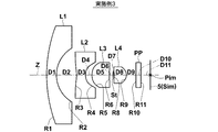
ここで、図2を参照しながら、上記の第2レンズL2の物体側の面の形状について説明する。図2は図1で示した撮像レンズ1の光路図である。図2において、点Q3は、第2レンズL2の物体側の面の中心であり、第2レンズL2の物体側の面と光軸Zとの交点である。図2の点X3は、第2レンズL2の物体側の面の有効径端の点であり、軸外光束4に含まれる最も外側の光線6と第2レンズL2の物体側の面との交点である。
Here, the shape of the object-side surface of the second lens L2 will be described with reference to FIG. FIG. 2 is an optical path diagram of the
このとき、点X3でのレンズ面の法線と光軸Zとの交点を図2に示すように点P3とし、点X3と点P3を結ぶ線分X3−P3を点X3での曲率半径RX3と定義し、線分X3−P3の長さ|X3−P3|を曲率半径RX3の絶対値|RX3|と定義する。すなわち、|X3−P3|=|RX3|である。また、点Q3での曲率半径、すなわち、第2レンズL2の物体側の面の中心の曲率半径をR3とし、その絶対値を|R3|とする(図2では不図示)。 At this time, the intersection of the normal of the lens surface at the point X3 and the optical axis Z is a point P3 as shown in FIG. 2, and a line segment X3-P3 connecting the point X3 and the point P3 is a radius of curvature RX3 at the point X3. The length | X3-P3 | of the line segment X3-P3 is defined as the absolute value | RX3 | of the curvature radius RX3. That is, | X3-P3 | = | RX3 |. Further, the radius of curvature at the point Q3, that is, the radius of curvature of the center of the object side surface of the second lens L2 is R3, and its absolute value is | R3 | (not shown in FIG. 2).
上記の第2レンズL2の物体側の面の「中心で負のパワーを持ち」とは、点Q3を含む近軸領域が凹形状であることを意味する。また、上記の第2レンズL2の物体側の面の「有効径端では中心と比較して負のパワーが弱い形状」とは、点P3が点Q3より物体側にあり、点X3での曲率半径の絶対値|RX3|が点Q3での曲率半径の絶対値|R3|よりも大きい形状を意味する。 “Having negative power at the center” on the object side surface of the second lens L2 means that the paraxial region including the point Q3 is concave. Further, “the shape where the negative power is weaker than the center at the effective diameter end” of the object side surface of the second lens L2 means that the point P3 is closer to the object side than the point Q3, and the curvature at the point X3 is This means that the absolute value | RX3 | of the radius is larger than the absolute value | R3 | of the radius of curvature at the point Q3.
図2では理解を助けるために、半径|R3|で点Q3を通り、光軸上の点を中心とする円CQ3を二点鎖線で描き、半径|RX3|で点X3を通り、光軸上の点を中心とする円CX3の一部を破線で描いている。円CX3の方が円CQ3よりも大きな円となっており、|R3|<|RX3|であることが明示されている。 In FIG. 2, in order to help understanding, a circle CQ3 centered on a point on the optical axis passes through a point Q3 with a radius | R3 |, and is drawn with a two-dot chain line, passes through a point X3 with a radius | RX3 | A part of a circle CX3 centered on the point is drawn with a broken line. The circle CX3 is larger than the circle CQ3, and it is clearly indicated that | R3 | <| RX3 |.
第2レンズL2の物体側の面は、中心で負のパワーを持ち、有効径端では正のパワーを持つ形状としてもよい。第2レンズL2の物体側の面をこのような形状とすることで、広角化と同時に像面湾曲とディストーションを良好に補正することが可能となる。 The object side surface of the second lens L2 may have a shape having negative power at the center and positive power at the effective diameter end. By forming the object side surface of the second lens L2 in such a shape, it becomes possible to favorably correct the field curvature and distortion at the same time as widening the angle.
上記の第2レンズL2の物体側の面の「中心で負のパワーを持ち」とは、点Q3を含む近軸領域が凹形状であることを意味する。また、上記の第2レンズL2の物体側の面の「有効径端では正のパワーを持つ形状」とは、点P3が点Q3より像側にある形状を意味する。 “Having negative power at the center” on the object side surface of the second lens L2 means that the paraxial region including the point Q3 is concave. The “shape having positive power at the effective diameter end” of the object side surface of the second lens L2 means a shape in which the point P3 is located on the image side from the point Q3.
点X3での曲率半径の絶対値|RX3|は、点Q3での曲率半径の絶対値|R3|の5.0倍より大きいこと、すなわち、5.0<|RX3|/|R3|であることが好ましく、この場合には像面湾曲とディストーションの補正が容易となる。 The absolute value | RX3 | of the radius of curvature at the point X3 is larger than 5.0 times the absolute value | R3 | of the radius of curvature at the point Q3, that is, 5.0 <| RX3 | / | R3 |. In this case, it is easy to correct curvature of field and distortion.
第2レンズL2の像側の面は、中心が負のパワーを持ち、有効径端では中心と比較して負のパワーが強い形状であることが好ましい。第2レンズL2の像側の面をこのような形状とすることで、像面湾曲の良好な補正が可能となる。 It is preferable that the image-side surface of the second lens L2 has a negative power at the center and has a stronger negative power than the center at the effective diameter end. By making the image side surface of the second lens L2 in such a shape, it is possible to correct the curvature of field favorably.
第2レンズL2の像側の面の上記形状は、図2を用いて説明した第2レンズL2の物体側の面の形状と同様にして以下のように考えることができる。レンズ断面図において、第2レンズL2の像側の面の有効径端を点X4として、その点での法線と光軸Zとの交点を点P4とするとき、点X4と点P4とを結ぶ線分X4−P4を点X4での曲率半径とし、点X4と点P4とを結ぶ線分の長さ|X4−P4|を点X4での曲率半径の絶対値|RX4|とする。よって、|X4−P4|=|RX4|となる。また、第2レンズL2の像側の面と光軸Zとの交点、すなわち、第2レンズL2の像側の面の中心を点Q4とする。そして、点Q4での曲率半径の絶対値を|R4|とする。 The shape of the image side surface of the second lens L2 can be considered as follows in the same manner as the shape of the object side surface of the second lens L2 described with reference to FIG. In the lens cross-sectional view, when the effective diameter end of the image side surface of the second lens L2 is a point X4 and the intersection of the normal line at that point and the optical axis Z is a point P4, the point X4 and the point P4 are The connecting line segment X4-P4 is defined as the radius of curvature at the point X4, and the length | X4-P4 | of the line segment connecting the point X4 and the point P4 is defined as the absolute value | RX4 | of the radius of curvature at the point X4. Therefore, | X4-P4 | = | RX4 |. Further, an intersection of the image side surface of the second lens L2 and the optical axis Z, that is, the center of the image side surface of the second lens L2 is defined as a point Q4. The absolute value of the radius of curvature at the point Q4 is set to | R4 |.
第2レンズL2の像側の面の「中心が負のパワーを持ち、有効径端では中心と比較して負のパワーが強い形状」とは、点Q4を含む近軸領域で凹形状であり、点P4が点Q4より像側にあり、かつ、点X4での曲率半径の絶対値|RX4|が点Q4での曲率半径の絶対値|R4|よりも小さい形状である。 “The shape of the image side surface of the second lens L2 having negative power at the center and stronger negative power than the center at the effective diameter end” is a concave shape in the paraxial region including the point Q4. The point P4 is closer to the image side than the point Q4, and the absolute value | RX4 | of the radius of curvature at the point X4 is smaller than the absolute value | R4 | of the radius of curvature at the point Q4.
点X4での曲率半径の絶対値|RX4|は、点Q4での曲率半径の絶対値|R4|の0.9倍より小さいこと、すなわち、0.9>|RX4|/|R4|であることが好ましく、この場合には像面湾曲の補正が容易となる。 The absolute value | RX4 | of the radius of curvature at the point X4 is smaller than 0.9 times the absolute value | R4 | of the radius of curvature at the point Q4, that is, 0.9> | RX4 | / | R4 |. In this case, it is easy to correct curvature of field.
第3レンズL3は、近軸領域において、両凸形状のレンズであることが望ましい。この構成により、像面湾曲と共に倍率の色収差も良好に補正可能となる。 The third lens L3 is desirably a biconvex lens in the paraxial region. With this configuration, it is possible to satisfactorily correct lateral chromatic aberration as well as field curvature.
第3レンズL3の物体側の面は、非球面とすることが望ましい。第3レンズL3の物体側の面は、中心が正のパワーを持ち、有効径端では中心と比較して正のパワーが強い形状であることが好ましい。第3レンズL3の物体側の面をこのような形状とすることで、像面湾曲とコマ収差を良好に補正することが可能となる。 The object side surface of the third lens L3 is preferably an aspherical surface. It is preferable that the object side surface of the third lens L3 has a positive power at the center and a shape having a stronger positive power than the center at the effective diameter end. By making the object side surface of the third lens L3 into such a shape, it is possible to favorably correct curvature of field and coma.
第3レンズL3の物体側の面の上記形状は、図2を用いて説明した第2レンズL2の物体側の面の形状と同様にして以下のように考えることができる。レンズ断面図において、第3レンズL3の物体側の面の有効径端を点X5として、その点での法線と光軸Zとの交点を点P5とするとき、点X5と点P5とを結ぶ線分X5−P5を点X5での曲率半径とし、点X5と点P5とを結ぶ線分の長さ|X5−P5|を点X5での曲率半径の絶対値|RX5|とする。よって、|X5−P5|=|RX5|となる。また、第3レンズL3の物体側の面と光軸Zとの交点、すなわち、第3レンズL3の物体側の面の中心を点Q5とする。そして、点Q5での曲率半径の絶対値を|R5|とする。 The shape of the object side surface of the third lens L3 can be considered as follows in the same manner as the shape of the object side surface of the second lens L2 described with reference to FIG. In the lens cross-sectional view, when the effective diameter end of the object-side surface of the third lens L3 is a point X5 and the intersection of the normal at that point and the optical axis Z is a point P5, the point X5 and the point P5 are The connecting line segment X5-P5 is defined as the radius of curvature at the point X5, and the length | X5-P5 | of the line segment connecting the point X5 and the point P5 is defined as the absolute value | RX5 | of the radius of curvature at the point X5. Therefore, | X5-P5 | = | RX5 |. Further, the intersection point between the object side surface of the third lens L3 and the optical axis Z, that is, the center of the object side surface of the third lens L3 is defined as a point Q5. And let the absolute value of the radius of curvature at the point Q5 be | R5 |.
第3レンズL3の物体側の面の「中心が正のパワーを持ち、有効径端では中心と比較して正のパワーが強い形状」とは、点Q5を含む近軸領域で凸形状であり、点P5が点Q5より像側にあり、かつ、点X5での曲率半径の絶対値|RX5|が点Q5での曲率半径の絶対値|R5|よりも小さい形状である。 “The shape having a positive power at the center and a stronger positive power than the center at the effective diameter end” of the object side surface of the third lens L3 is a convex shape in the paraxial region including the point Q5. The point P5 is on the image side with respect to the point Q5, and the absolute value | RX5 | of the radius of curvature at the point X5 is smaller than the absolute value | R5 | of the radius of curvature at the point Q5.
点X5での曲率半径の絶対値|RX5|は、点Q5での曲率半径の絶対値|R5|の1.0倍より小さいこと、すなわち、1.0>|RX5|/|R5|であることが好ましく、この場合には像面湾曲とコマ収差の補正が容易となる。 The absolute value | RX5 | of the radius of curvature at the point X5 is smaller than 1.0 times the absolute value | R5 | of the radius of curvature at the point Q5, that is, 1.0> | RX5 | / | R5 |. In this case, it is easy to correct curvature of field and coma.
第3レンズL3の像側の面は、非球面とすることが望ましい。第3レンズL3の像側の面は、中心が正のパワーを持ち、有効径端では負のパワーを持つことが好ましい。第3レンズL3の像側の面をこのような形状とすることで、像面湾曲を良好に補正することが可能となる。 The image side surface of the third lens L3 is preferably an aspherical surface. The image-side surface of the third lens L3 preferably has a positive power at the center and a negative power at the effective diameter end. By setting the image side surface of the third lens L3 to have such a shape, it is possible to favorably correct curvature of field.
第3レンズL3の像側の面の上記形状は、図2を用いて説明した第2レンズL2の物体側の面の形状と同様にして以下のように考えることができる。レンズ断面図において、第3レンズL3の像側の面の有効径端を点X6として、その点での法線と光軸Zとの交点を点P6とするとき、点X6と点P6とを結ぶ線分X6−P6を点X6での曲率半径とし、点X6と点P6とを結ぶ線分の長さ|X6−P6|を点X6での曲率半径の絶対値|RX6|とする。よって、|X6−P6|=|RX6|となる。また、第3レンズL3の像側の面と光軸Zとの交点、すなわち、第3レンズL3の像側の面の中心を点Q6とする。そして、点Q6での曲率半径の絶対値を|R6|とする。 The shape of the image side surface of the third lens L3 can be considered as follows in the same manner as the shape of the object side surface of the second lens L2 described with reference to FIG. In the lens cross-sectional view, when the effective diameter end of the image side surface of the third lens L3 is a point X6 and the intersection of the normal line at that point and the optical axis Z is a point P6, the point X6 and the point P6 are The connecting line segment X6-P6 is defined as the radius of curvature at the point X6, and the length | X6-P6 | of the line segment connecting the point X6 and the point P6 is defined as the absolute value | RX6 | of the radius of curvature at the point X6. Therefore, | X6-P6 | = | RX6 |. Further, the intersection point between the image side surface of the third lens L3 and the optical axis Z, that is, the center of the image side surface of the third lens L3 is defined as a point Q6. And let the absolute value of the radius of curvature at the point Q6 be | R6 |.
第3レンズL3の像側の面の「中心が正のパワーを持ち、有効径端では負のパワーを持つ形状」とは、点Q6を含む近軸領域で凸形状であり、点P6が点Q6より像側にある形状である。 The “shape having a positive power at the center and a negative power at the effective diameter end” on the image side surface of the third lens L3 is a convex shape in the paraxial region including the point Q6, and the point P6 is a point. The shape is located on the image side from Q6.
点X6での曲率半径の絶対値|RX6|は、点Q6での曲率半径の絶対値|R6|の2.0倍より大きいこと、すなわち、2.0<|RX6|/|R6|であることが好ましく、この場合には像面湾曲の補正が容易となる。 The absolute value | RX6 | of the radius of curvature at the point X6 is larger than 2.0 times the absolute value | R6 | of the radius of curvature at the point Q6, that is, 2.0 <| RX6 | / | R6 |. In this case, it is easy to correct curvature of field.
第4レンズL4は、近軸領域において正メニスカスレンズであることが望ましい。この構成により、球面収差、像面湾曲を良好に補正することが可能となる。 The fourth lens L4 is preferably a positive meniscus lens in the paraxial region. With this configuration, it is possible to satisfactorily correct spherical aberration and field curvature.
第4レンズL4の物体側の面は、非球面とすることが望ましい。第4レンズL4の物体側の面は、中心が負のパワーを持ち、有効径端では中心と比較して負のパワーが強い形状であることが好ましい。第4レンズL4の物体側の面をこのような形状とすることで、球面収差とコマ収差、像面湾曲を良好に補正することが可能となる。 The object side surface of the fourth lens L4 is preferably an aspherical surface. It is preferable that the object side surface of the fourth lens L4 has a negative power at the center and a shape having a stronger negative power than the center at the effective diameter end. By setting the object side surface of the fourth lens L4 to such a shape, it is possible to satisfactorily correct spherical aberration, coma aberration, and field curvature.
第4レンズL4の物体側の面の上記形状は、図2を用いて説明した第2レンズL2の物体側の面の形状と同様にして以下のように考えることができる。レンズ断面図において、第4レンズL4の物体側の面の有効径端を点X8として、その点での法線と光軸Zとの交点を点P8とするとき、点X8と点P8とを結ぶ線分X8−P8を点X8での曲率半径とし、点X8と点P8とを結ぶ線分の長さ|X8−P8|を点X8での曲率半径の絶対値|RX8|とする。よって、|X8−P8|=|RX8|となる。また、第4レンズL4の物体側の面と光軸Zとの交点、すなわち、第4レンズL4の物体側の面の中心を点Q8とする。そして、点Q8での曲率半径の絶対値を|R8|とする。 The shape of the object side surface of the fourth lens L4 can be considered as follows in the same manner as the shape of the object side surface of the second lens L2 described with reference to FIG. In the lens cross-sectional view, when the effective diameter end of the object-side surface of the fourth lens L4 is a point X8 and the intersection of the normal at that point and the optical axis Z is a point P8, the point X8 and the point P8 are The connecting line segment X8-P8 is defined as the radius of curvature at the point X8, and the length | X8-P8 | of the line segment connecting the point X8 and the point P8 is defined as the absolute value | RX8 | of the radius of curvature at the point X8. Therefore, | X8−P8 | = | RX8 |. Further, the intersection point between the object side surface of the fourth lens L4 and the optical axis Z, that is, the center of the object side surface of the fourth lens L4 is defined as a point Q8. And let the absolute value of the radius of curvature at the point Q8 be | R8 |.
第4レンズL4の物体側の面の「中心が負のパワーを持ち、有効径端では中心と比較して負のパワーが強い形状」とは、点Q8を含む近軸領域で凹形状であり、点P8が点Q8より物体側にあり、かつ、点X8での曲率半径の絶対値|RX8|が点Q8での曲率半径の絶対値|R8|よりも小さい形状である。 “The shape having a negative power at the center and a strong negative power at the effective diameter end” on the object side surface of the fourth lens L4 is a concave shape in the paraxial region including the point Q8. The point P8 is closer to the object than the point Q8, and the absolute value | RX8 | of the radius of curvature at the point X8 is smaller than the absolute value | R8 | of the radius of curvature at the point Q8.
点X8での曲率半径の絶対値|RX8|は、点Q8での曲率半径の絶対値|R8|の0.9倍より小さいこと、すなわち、0.9>|RX8|/|R8|であることが好ましく、この場合には像面湾曲の補正が容易となる。 The absolute value | RX8 | of the radius of curvature at the point X8 is smaller than 0.9 times the absolute value | R8 | of the radius of curvature at the point Q8, that is, 0.9> | RX8 | / | R8 |. In this case, it is easy to correct curvature of field.
第4レンズL4の像側の面は、非球面とすることが望ましい。第4レンズL4の像側の面は、中心が正のパワーを持ち、有効径端では中心と比較して正のパワーが弱い形状であることが好ましい。第4レンズL4をこのような形状とすることで、球面収差、像面湾曲、コマ収差の良好な補正が可能となる。 The image side surface of the fourth lens L4 is preferably an aspherical surface. It is preferable that the image-side surface of the fourth lens L4 has a positive power at the center and has a weaker positive power than the center at the effective diameter end. When the fourth lens L4 has such a shape, it is possible to satisfactorily correct spherical aberration, curvature of field, and coma.
第4レンズL4の像側の面の上記形状は、図2を用いて説明した第2レンズL2の物体側の面の形状と同様にして以下のように考えることができる。レンズ断面図において、第4レンズL4の像側の面の有効径端を点X9として、その点での法線と光軸Zとの交点を点P9とするとき、点X9と点P9とを結ぶ線分X9−P9を点X9での曲率半径とし、点X9と点P9とを結ぶ線分の長さ|X9−P9|を点X9での曲率半径の絶対値|RX9|とする。よって、|X9−P9|=|RX9|となる。また、第4レンズL4の像側の面と光軸Zとの交点、すなわち、第4レンズL4の像側の面の中心を点Q9とする。そして、点Q9での曲率半径の絶対値を|R9|とする。 The shape of the image side surface of the fourth lens L4 can be considered as follows in the same manner as the shape of the object side surface of the second lens L2 described with reference to FIG. In the lens cross-sectional view, when the effective diameter end of the image side surface of the fourth lens L4 is a point X9 and the intersection of the normal line at that point and the optical axis Z is a point P9, the point X9 and the point P9 are The connecting line segment X9-P9 is defined as the radius of curvature at the point X9, and the length | X9-P9 | of the line segment connecting the point X9 and the point P9 is defined as the absolute value | RX9 | of the radius of curvature at the point X9. Therefore, | X9−P9 | = | RX9 |. Further, an intersection of the image side surface of the fourth lens L4 and the optical axis Z, that is, the center of the image side surface of the fourth lens L4 is defined as a point Q9. The absolute value of the radius of curvature at the point Q9 is assumed to be | R9 |.
第4レンズL4の像側の面の「中心が正のパワーを持ち、有効径端では中心と比較して正のパワーが弱い形状」とは、点Q9を含む近軸領域で凸形状であり、点P9が点Q9より物体側にあり、かつ、点X9での曲率半径の絶対値|RX9|が点Q9での曲率半径の絶対値|R9|よりも大きい形状である。 “The shape of the image side surface of the fourth lens L4 having positive power at the center and weaker than the center at the effective diameter end” is a convex shape in the paraxial region including the point Q9. The point P9 is closer to the object side than the point Q9, and the absolute value | RX9 | of the radius of curvature at the point X9 is larger than the absolute value | R9 | of the radius of curvature at the point Q9.
点X9での曲率半径の絶対値|RX9|は、点Q9での曲率半径の絶対値|R9|の1.1倍より大きいこと、すなわち、1.1<|RX9|/|R9|であることが好ましく、この場合には球面収差、像面湾曲、コマ収差の補正が容易となる。 The absolute value | RX9 | of the radius of curvature at the point X9 is greater than 1.1 times the absolute value | R9 | of the radius of curvature at the point Q9, that is, 1.1 <| RX9 | / | R9 | In this case, it is easy to correct spherical aberration, curvature of field, and coma.
第2レンズL2の物体側の面から第4レンズL4の像側の面までの各面を上記のような非球面形状とすることで、球面収差、像面湾曲、コマ収差に加えてディストーションまで良好に補正することが可能となる。 By making each surface from the object-side surface of the second lens L2 to the image-side surface of the fourth lens L4 an aspherical shape as described above, distortion is added in addition to spherical aberration, field curvature, and coma. It becomes possible to correct well.
なお、第3レンズL3の像側の面は、中心が負のパワーを持ち、有効径端では中心と比較して負のパワーが強い形状であるように構成してもよく、その場合は、球面収差の補正が容易となる。 In addition, the image side surface of the third lens L3 may be configured such that the center has a negative power and the negative power is stronger than the center at the effective diameter end. Correction of spherical aberration becomes easy.
上記で定義した記号を用いて説明すれば、第3レンズL3の像側の面の「中心が負のパワーを持ち、有効径端では中心と比較して負のパワーが強い形状」とは、点Q6を含む近軸領域で凹形状であり、点P6が点Q6より像側にあり、かつ、点X6での曲率半径の絶対値|RX6|が点Q6での曲率半径の絶対値|R6|よりも小さい形状である。 If it demonstrates using the symbol defined above, "the shape where the center has negative power and the negative power is stronger than the center at the effective diameter end" of the image side surface of the third lens L3 is: The paraxial region including the point Q6 has a concave shape, the point P6 is closer to the image side than the point Q6, and the absolute value | RX6 | of the radius of curvature at the point X6 is the absolute value of the radius of curvature at the point Q6 | R6 The shape is smaller than |.
ディストーションは、全系の焦点距離をf、画角をφ(変数扱い、0≦φ≦ω、ωは半画角)とし、理想像高を2f×tan(φ/2)として、それからのずれ量を示すものとした場合、中心から最大画角まで正の値であることが望ましい。ディストーションを理想像高2f×tan(φ/2)に対して中心から最大画角まで正の値とすることで、ディストーションによる周辺の画像のつぶれを最小限に抑えることが可能となり、画像劣化を抑えることが可能となる。 Distortion is set so that the focal length of the entire system is f, the field angle is φ (variable treatment, 0 ≦ φ ≦ ω, ω is a half field angle), and the ideal image height is 2f × tan (φ / 2). When the amount is shown, it is desirable that the value is positive from the center to the maximum angle of view. By setting the distortion to a positive value from the center to the maximum angle of view with respect to the ideal image height of 2f × tan (φ / 2), it is possible to minimize the collapse of the surrounding image due to the distortion, thereby reducing image degradation. It becomes possible to suppress.
第1レンズL1の材質のd線におけるアッベ数は40以上であることが好ましく、これにより、色収差の発生を抑え、良好な解像性能を得ることが可能となる。第2レンズL2の材質のd線におけるアッベ数は40以上であることが好ましく、これにより、色収差の発生を抑え、良好な解像性能を得ることが可能となる。第4レンズL4の材質のd線におけるアッベ数は40以上であることが好ましく、これにより、色収差の発生を抑え、良好な解像性能を得ることが可能となる。 The Abbe number of the material of the first lens L1 on the d-line is preferably 40 or more, which makes it possible to suppress the occurrence of chromatic aberration and to obtain good resolution performance. The Abbe number in the d-line of the material of the second lens L2 is preferably 40 or more, which makes it possible to suppress the occurrence of chromatic aberration and to obtain good resolution performance. The Abbe number of the material of the fourth lens L4 on the d-line is preferably 40 or more, which makes it possible to suppress the occurrence of chromatic aberration and to obtain good resolution performance.
第3レンズL3の材質のd線におけるアッベ数は30以下であることが好ましく、これにより、倍率の色収差を良好に補正することが可能となる。さらに、第3レンズL3の材質のd線におけるアッベ数を28以下にすることが好ましく、この場合には、倍率の色収差をより良好に補正することが可能となる。 The Abbe number in the d-line of the material of the third lens L3 is preferably 30 or less, which makes it possible to correct chromatic aberration of magnification satisfactorily. Furthermore, it is preferable that the Abbe number of the material of the third lens L3 on the d-line is 28 or less, and in this case, it is possible to more appropriately correct the chromatic aberration of magnification.
第1レンズL1の材質はガラスであることが好ましい。撮像レンズが例えば車載用カメラや監視カメラ用等の厳しい環境において使用される場合には、最も物体側に配置される第1レンズL1は、風雨による表面劣化、直射日光による温度変化に強く、さらには油脂・洗剤等の化学薬品に強い材質、すなわち耐水性、耐候性、耐酸性、耐薬品性等が高い材質を用いることが要望され、また、堅く、割れにくい材質を用いることが要望されることがある。材質をガラスとすることで、これらの要望を満たすことが可能となる。また、第1レンズL1の材質として、透明なセラミックスを用いてもよい。 The material of the first lens L1 is preferably glass. When the imaging lens is used in a harsh environment such as an in-vehicle camera or a surveillance camera, the first lens L1 disposed closest to the object side is resistant to surface deterioration due to wind and rain, temperature change due to direct sunlight, Is required to use materials that are resistant to chemicals such as oils and detergents, that is, materials with high water resistance, weather resistance, acid resistance, chemical resistance, etc., and materials that are hard and hard to break are required. Sometimes. These requirements can be satisfied by using glass as the material. Moreover, you may use transparent ceramics as a material of the 1st lens L1.
例えば車載カメラ用レンズにおいては、レンズは各種衝撃に耐えることが求められる。そのため第1レンズL1は厚いことが望ましい。第1レンズL1の中心厚は1.7mm以上であることが望ましい。さらに第1レンズL1を割れにくくするためには、第1レンズL1の中心厚が1.75mm以上であることが望ましい。さらにより第1レンズL1を割れにくくするためには、第1レンズL1の中心厚が1.80mm以上であることが望ましい。 For example, in an in-vehicle camera lens, the lens is required to withstand various impacts. Therefore, it is desirable that the first lens L1 is thick. The center thickness of the first lens L1 is desirably 1.7 mm or more. Further, in order to make the first lens L1 difficult to break, it is desirable that the center thickness of the first lens L1 is 1.75 mm or more. Furthermore, in order to make the first lens L1 more difficult to break, it is desirable that the center thickness of the first lens L1 is 1.80 mm or more.
なお、第1レンズL1の物体側の面に、強度、耐キズ性、耐薬品性を高めるための保護手段を施してもよく、その場合には、第1レンズL1の材質をプラスチックとしてもよい。このような保護手段は、ハードコートであってもよく、撥水コートであってもよい。 It should be noted that a protective means for enhancing the strength, scratch resistance and chemical resistance may be applied to the object side surface of the first lens L1, and in this case, the material of the first lens L1 may be plastic. . Such protective means may be a hard coat or a water repellent coat.
第2レンズL2、第3レンズL3、第4レンズL4のいずれか、あるいはこれらのうちの任意の複数の組合せにおいて、その材質をプラスチックとすることが好ましい。材質をプラスチックとすることで、レンズ系を安価で軽量に構成することが可能となるとともに、非球面を設けた場合には、非球面形状を正確に作製することができるため、良好な性能のレンズを作製することが可能となる。 In any one of the second lens L2, the third lens L3, the fourth lens L4, or any combination of these, it is preferable that the material is plastic. By using plastic as the material, it is possible to configure the lens system at a low cost and light weight, and when an aspheric surface is provided, the aspherical shape can be accurately produced, so that a good performance can be obtained. A lens can be manufactured.
第2レンズL2、第3レンズL3、第4レンズL4の少なくともいずれか1つにプラスチック材質を用いた場合は、その材質として、プラスチックに光の波長より小さな粒子を混合させたいわゆるナノコンポジット材料を用いてもよい。 When a plastic material is used for at least one of the second lens L2, the third lens L3, and the fourth lens L4, a so-called nanocomposite material in which particles smaller than the wavelength of light are mixed into the plastic is used as the material. It may be used.
第2レンズL2、第3レンズL3、第4レンズL4のいずれか、あるいはこれらのうちの任意の複数の組合せにおいて、その材質をガラスとしてもよい。材質をガラスとすることで、温度変化による性能劣化を抑制することが可能となる。 The material of the second lens L2, the third lens L3, the fourth lens L4, or any combination of these may be glass. By using glass as the material, it is possible to suppress performance deterioration due to temperature changes.
第1レンズL1、第2レンズL2、第3レンズL3、第4レンズL4の少なくともいずれか1つは、その材質のガラス転移温度(Tg)が145℃以上であることが好ましく、さらに好ましくは、150℃以上であることが好ましい。ガラス転移温度が150℃以上の材質を使用することで、耐熱性の良いレンズを作成することが可能となる。 At least one of the first lens L1, the second lens L2, the third lens L3, and the fourth lens L4 preferably has a glass transition temperature (Tg) of 145 ° C. or higher, more preferably, It is preferable that it is 150 degreeC or more. By using a material having a glass transition temperature of 150 ° C. or higher, a lens having good heat resistance can be created.
なお、撮像レンズ1の用途に応じて、レンズ系と撮像素子5との間に紫外光から青色光をカットするようなフィルタ、または赤外光をカットするようなIR(InfraRed)カットフィルタを挿入してもよい。上記フィルタと同様の特性を持つコートをレンズ面に塗布してもよい。またはいずれかのレンズの材質として紫外光や青色光、赤外光などを吸収する材質を用いてもよい。
Depending on the application of the
図1では、レンズ系と撮像素子5との間に各種フィルタ等を想定した光学部材PPを配置した例を示しているが、この代わりに、各レンズの間にこれらの各種フィルタを配置してもよい。あるいは、撮像レンズが有するいずれかのレンズのレンズ面に、各種フィルタと同様の作用を有するコートを施してもよい。
FIG. 1 shows an example in which the optical member PP assuming various filters is arranged between the lens system and the
なお、各レンズ間の有効径外を通過する光束は、迷光となって像面に達し、ゴーストとなるおそれがあるため、必要に応じて、この迷光を遮光する遮光手段を設けることが好ましい。この遮光手段としては、例えばレンズの有効径外の部分に不透明な塗料を施したり、不透明な板材を設けたりしてもよい。または、迷光となる光束の光路に不透明な板材を設けて遮光手段としてもよい。あるいは、最も物体側のレンズのさらに物体側に迷光を遮断するフードのようなものを配置してもよい。一例として、図1では、第1レンズL1、第2レンズL2それぞれの像側の面の有効径外に遮光手段11、12を設けた例を示している。なお、遮光手段を設ける箇所は図1に示す例に限定されず、他のレンズや、レンズ間に配置してもよい。
Note that the light flux that passes outside the effective diameter between the lenses reaches the image plane as stray light and may become a ghost. Therefore, if necessary, it is preferable to provide a light shielding unit that shields the stray light. As the light shielding means, for example, an opaque paint may be applied to a portion outside the effective diameter of the lens, or an opaque plate material may be provided. Alternatively, an opaque plate material may be provided in the optical path of a light beam that becomes stray light to serve as a light shielding unit. Alternatively, a hood that blocks stray light may be disposed further on the object side of the most object side lens. As an example, FIG. 1 shows an example in which the
さらに、各レンズの間に周辺光量比が実用上問題の無い範囲で周辺光線を遮断する絞り等の部材を配置してもよい。周辺光線とは、光軸Z外の物点からの光線のうち、光学系の入射瞳の周辺部分を通る光線のことである。このように周辺光線を遮断する部材を配置することにより、結像領域周辺部の画質を向上させることができる。また、この部材でゴーストを発生させる光を遮断することにより、ゴーストを低減することが可能となる。 Further, a member such as a diaphragm that blocks the peripheral light beam may be disposed between the lenses so long as the peripheral light amount ratio has no practical problem. A peripheral ray is a ray that passes through a peripheral portion of the entrance pupil of the optical system among rays from an object point outside the optical axis Z. By disposing the member that blocks the peripheral light in this way, the image quality in the periphery of the imaging region can be improved. Moreover, it becomes possible to reduce a ghost by interrupting | blocking the light which generates a ghost with this member.
〔撮像レンズの数値実施例〕
次に、本発明の撮像レンズの数値実施例について説明する。実施例1〜実施例5の撮像レンズのレンズ断面図をそれぞれ図3〜図7に示す。図3〜図7において、図の左側が物体側、右側が像側であり、図1同様、開口絞りSt、光学部材PP、像面Simに配置された撮像素子5も合せて図示している。各図の開口絞りStは形状や大きさを表すものではなく、光軸Z上の位置を示すものである。各実施例において、レンズ断面図の符号Ri、Di(i=1、2、3、…)は以下に説明するレンズデータのRi、Diと対応している。
[Numerical example of imaging lens]
Next, numerical examples of the imaging lens of the present invention will be described. 3 to 7 are lens cross-sectional views of the imaging lenses of Examples 1 to 5, respectively. 3 to 7, the left side of the figure is the object side, and the right side is the image side, and similarly to FIG. 1, the aperture stop St, the optical member PP, and the
実施例1にかかる撮像レンズのレンズデータおよび各種データを表1に、非球面データを表2に、曲率半径に関するデータを表3に示す。同様に、実施例2〜5にかかる撮像レンズのレンズデータおよび各種データ、非球面データをそれぞれ表4〜表15に示す。以下では表中の記号の意味について、実施例1を例にとり説明するが、実施例2〜5のものについても基本的に同様である。 Table 1 shows lens data and various data of the imaging lens according to Example 1, Table 2 shows aspherical data, and Table 3 shows data related to the radius of curvature. Similarly, lens data, various data, and aspherical data of the imaging lenses according to Examples 2 to 5 are shown in Tables 4 to 15, respectively. In the following, the meaning of the symbols in the table will be described using Example 1 as an example, but the same applies to Examples 2 to 5.
表1のレンズデータにおいて、Siは最も物体側の構成要素の面を1番目として像側に向かうに従い順次増加するi番目(i=1、2、3、…)の面番号を示し、Riはi番目の面の曲率半径を示し、Diはi番目の面とi+1番目の面との光軸Z上の面間隔を示している。なお、曲率半径の符号は、物体側に凸の場合を正、像側に凸の場合を負としている。 In the lens data of Table 1, Si indicates the i-th (i = 1, 2, 3,...) Surface number that sequentially increases toward the image side with the most object-side component surface being first, and Ri is The radius of curvature of the i-th surface is indicated, and Di indicates the surface interval on the optical axis Z between the i-th surface and the i + 1-th surface. The sign of the radius of curvature is positive when convex on the object side and negative when convex on the image side.
また、レンズデータにおいて、Ndjは最も物体側のレンズを1番目として像側に向かうに従い順次増加するj番目(j=1、2、3、…)の光学要素のd線(波長587.6nm)に対する屈折率を示し、νdjはj番目の光学要素のd線に対するアッベ数を示している。なお、レンズデータには、開口絞りStおよび光学部材PPも含めて示しており、開口絞りStに相当する面の面番号の欄には、(開口絞り)という語句も合わせて記載している。 In the lens data, Ndj is the first object-side lens, and the d-line (wavelength 587.6 nm) of the j-th (j = 1, 2, 3,...) Optical element increases sequentially toward the image side. Νdj represents the Abbe number of the j-th optical element with respect to the d-line. The lens data includes the aperture stop St and the optical member PP, and the term “aperture stop” is also described in the surface number column of the surface corresponding to the aperture stop St.
表1の各種データにおいて、Fno.はFナンバー、2ωは全画角、Bfは最も像側のレンズの像側の面から像面までの光軸Z上の距離(バックフォーカスに相当、空気換算長)、Lは第1レンズL1の物体側の面から像面Simまでの光軸Z上の距離(バックフォーカス分は空気換算長)、ED1は第1レンズL1の物体側の面の有効径、fは全系の焦点距離、f1は第1レンズL1の焦点距離、f2は第2レンズL2の焦点距離、f3は第3レンズL3の焦点距離、f4は第4レンズL4の焦点距離、f12は第1レンズL1と第2レンズL2の合成焦点距離、f34は第3レンズL3と第4レンズL4の合成焦点距離、f23は第2レンズL2と第3レンズL3の合成焦点距離である。 In the various data in Table 1, Fno. Is the F number, 2ω is the total angle of view, Bf is the distance on the optical axis Z from the image side surface of the lens closest to the image side to the image plane (corresponding to back focus, air conversion length), and L is the first lens L1. The distance on the optical axis Z from the object side surface to the image plane Sim (the back focus component is an air conversion length), ED1 is the effective diameter of the object side surface of the first lens L1, f is the focal length of the entire system, f1 is the focal length of the first lens L1, f2 is the focal length of the second lens L2, f3 is the focal length of the third lens L3, f4 is the focal length of the fourth lens L4, and f12 is the first lens L1 and the second lens. The combined focal length of L2, f34 is the combined focal length of the third lens L3 and the fourth lens L4, and f23 is the combined focal length of the second lens L2 and the third lens L3.
表1のレンズデータでは、非球面の面番号に*印を付しており、非球面の曲率半径として光軸近傍の曲率半径(中心の曲率半径)の数値を示している。表2の非球面データには、非球面の面番号と、各非球面に関する非球面係数を示す。表2の非球面データの数値の「E−n」(n:整数)は「×10−n」を意味し、「E+n」は「×10n」を意味する。なお、非球面係数は、以下の式(A)で表される非球面式における各係数KA、RBm(m=3、4、5、…20)の値である。
Zd=C・h2/{1+(1−KA・C2・h2)1/2}+ΣRBm・hm … (A)
ただし、
Zd:非球面深さ(高さhの非球面上の点から、非球面頂点が接する光軸に垂直な平面に
下ろした垂線の長さ)
h:高さ(光軸からのレンズ面までの距離)
C:近軸曲率半径の逆数
KA、RBm:非球面係数(m=3、4、5、…20)
In the lens data of Table 1, the surface number of the aspheric surface is marked with *, and the numerical value of the curvature radius (center curvature radius) near the optical axis is shown as the curvature radius of the aspheric surface. The aspheric data in Table 2 shows the surface number of the aspheric surface and the aspheric coefficient for each aspheric surface. “E−n” (n: integer) in the numerical values of the aspheric surface data in Table 2 means “× 10 −n ”, and “E + n” means “× 10 n ”. The aspheric coefficient is a value of each coefficient KA, RB m (m = 3, 4, 5,... 20) in the aspheric expression expressed by the following expression (A).
Zd = C · h 2 / {1+ (1−KA · C 2 · h 2 ) 1/2 } + ΣRB m · h m (A)
However,
Zd: Depth of aspheric surface (length of perpendicular drawn from a point on the aspherical surface of height h to a plane perpendicular to the optical axis where the aspherical vertex contacts)
h: Height (distance from the optical axis to the lens surface)
C: Reciprocal number of paraxial radius of curvature KA, RB m : aspheric coefficient (m = 3, 4, 5,... 20)
表3の曲率半径に関するデータでは、面番号と、有効径端での曲率半径の絶対値、有効径端での曲率半径の絶対値と中心の曲率半径の絶対値の比を前述の説明の記号を用いて示している。|RX3|は第2レンズL2の物体側の面の有効径端での曲率半径の絶対値、|RX3|/|R3|は第2レンズL2の物体側の面の有効径端での曲率半径の絶対値と中心の曲率半径の絶対値の比である。|RX4|は第2レンズL2の像側の面の有効径端での曲率半径の絶対値、|RX4|/|R4|は第2レンズL2の像側の面の有効径端での曲率半径の絶対値と中心の曲率半径の絶対値の比である。|RX5|は第3レンズL3の物体側の面の有効径端での曲率半径の絶対値、|RX5|/|R5|は第3レンズL3の物体側の面の有効径端での曲率半径の絶対値と中心の曲率半径の絶対値の比である。|RX6|は第3レンズL3の像側の面の有効径端での曲率半径の絶対値、|RX6|/|R6|は第3レンズL3の像側の面の有効径端での曲率半径の絶対値と中心の曲率半径の絶対値の比である。|RX8|は第4レンズL4の物体側の面の有効径端での曲率半径の絶対値、|RX8|/|R8|は第4レンズL4の物体側の面の有効径端での曲率半径の絶対値と中心の曲率半径の絶対値の比である。|RX9|は第4レンズL4の像側の面の有効径端での曲率半径の絶対値、|RX9|/|R9|は第4レンズL4の像側の面の有効径端での曲率半径の絶対値と中心の曲率半径の絶対値の比である。 In the data on the radius of curvature in Table 3, the surface number, the absolute value of the radius of curvature at the end of the effective diameter, and the ratio of the absolute value of the radius of curvature at the end of the effective diameter and the absolute value of the center radius of curvature are the symbols described above. This is shown using. | RX3 | is the absolute value of the radius of curvature at the effective diameter end of the object side surface of the second lens L2, and | RX3 | / | R3 | is the radius of curvature at the effective diameter end of the object side surface of the second lens L2. Is the ratio of the absolute value of and the absolute value of the radius of curvature at the center. | RX4 | is the absolute value of the radius of curvature at the effective diameter end of the image side surface of the second lens L2, and | RX4 | / | R4 | is the radius of curvature at the effective diameter end of the image side surface of the second lens L2. Is the ratio of the absolute value of and the absolute value of the radius of curvature at the center. | RX5 | is the absolute value of the radius of curvature at the effective diameter end of the object side surface of the third lens L3, and | RX5 | / | R5 | is the radius of curvature at the effective diameter end of the object side surface of the third lens L3. Is the ratio of the absolute value of and the absolute value of the radius of curvature at the center. | RX6 | is the absolute value of the radius of curvature at the effective diameter end of the image side surface of the third lens L3, and | RX6 | / | R6 | is the radius of curvature at the effective diameter end of the image side surface of the third lens L3. Is the ratio of the absolute value of and the absolute value of the radius of curvature at the center. | RX8 | is the absolute value of the radius of curvature at the effective diameter end of the object side surface of the fourth lens L4, and | RX8 | / | R8 | is the radius of curvature at the effective diameter end of the object side surface of the fourth lens L4. Is the ratio of the absolute value of and the absolute value of the radius of curvature at the center. | RX9 | is the absolute value of the radius of curvature at the effective diameter end of the image side surface of the fourth lens L4, and | RX9 | / | R9 | is the radius of curvature at the effective diameter end of the image side surface of the fourth lens L4. Is the ratio of the absolute value of and the absolute value of the radius of curvature at the center.
なお、表1〜表3には、所定の桁でまるめた数値を記載している。各数値の単位としては、表1の2ωについては「度」を用い、長さについては「mm」を用いている。しかし、これは一例であり、光学系は比例拡大または比例縮小しても同等の光学性能が得られるので、他の適当な単位を用いることもできる。 In Tables 1 to 3, numerical values rounded by a predetermined digit are shown. As the unit of each numerical value, “degree” is used for 2ω in Table 1, and “mm” is used for the length. However, this is only an example, and the optical system can obtain the same optical performance even when proportionally enlarged or reduced, and therefore other appropriate units can be used.

上記実施例1〜5の撮像レンズでは全て、第1レンズL1はガラス球面レンズであるが、第1レンズL1の片側の面もしくは両側の面を非球面として用いてもよい。第1レンズL1をガラス非球面レンズとすることで、諸収差をさらに良好に補正することができる。 In all of the imaging lenses of Examples 1 to 5, the first lens L1 is a glass spherical lens, but one or both surfaces of the first lens L1 may be used as an aspheric surface. By using the first lens L1 as a glass aspheric lens, various aberrations can be corrected more satisfactorily.
また、上記実施例1〜5の撮像レンズにおける、第2レンズL2、第3レンズL3、第4レンズL4の材質は全てプラスチックであり、安価に作製可能である。 In the imaging lenses of Examples 1 to 5, the second lens L2, the third lens L3, and the fourth lens L4 are all made of plastic and can be manufactured at low cost.
実施例1〜5の撮像レンズにおける条件式(1)〜(14)に対応する値を表16に示す。実施例1〜5では、d線を基準波長としており、表16にはこの基準波長における各値を示す。 Table 16 shows values corresponding to the conditional expressions (1) to (14) in the imaging lenses of Examples 1 to 5. In Examples 1 to 5, the d-line is used as a reference wavelength, and Table 16 shows values at this reference wavelength.
実施例1にかかる撮像レンズの収差図を図8(A)〜図8(E)に示す。図8(A)〜図8(D)はそれぞれ、球面収差、非点収差、ディストーション(歪曲収差)、倍率色収差(倍率の色収差)を示している。図8(E)は、横収差の収差図であり、各半画角におけるタンジェンシャル方向、サジタル方向の5つの収差図をまとめて示している。各収差図には、d線(587.56nm)を基準波長とした収差を示すが、球面収差図および倍率の色収差図には、F線(波長486.13nm)、C線(波長656.27nm)、s線(波長852.11nm)についての収差も示す。球面収差図のFno.はFナンバーであり、その他の収差図のωは半画角を意味する。ディストーションの図は、全系の焦点距離f、画角φ(変数扱い、0≦φ≦ω)を用いて、理想像高を2f×tan(φ/2)とし、それからのずれ量を示す。 FIG. 8A to FIG. 8E show aberration diagrams of the imaging lens according to the first example. 8A to 8D show spherical aberration, astigmatism, distortion (distortion aberration), and lateral chromatic aberration (chromatic aberration of magnification), respectively. FIG. 8E is an aberration diagram of lateral aberration, and collectively shows five aberration diagrams in the tangential direction and the sagittal direction at each half angle of view. Each aberration diagram shows the aberration with the d-line (587.56 nm) as the reference wavelength, but the spherical aberration diagram and the chromatic aberration diagram of the magnification show the F-line (wavelength 486.13 nm) and the C-line (wavelength 656.27 nm). ), Aberrations for the s-line (wavelength 852.11 nm) are also shown. Fno. Of spherical aberration diagram. Is the F number, and ω in other aberration diagrams means a half angle of view. The distortion diagram shows the amount of deviation from the ideal image height of 2f × tan (φ / 2) using the focal length f and the angle of view φ (variable treatment, 0 ≦ φ ≦ ω) of the entire system.
また同様に、上記実施例2〜5にかかる撮像レンズの球面収差、非点収差、ディストーション(歪曲収差)、倍率色収差(倍率の色収差)、横収差の収差図をそれぞれ図9(A)〜図9(E)、図10(A)〜図10(E)、図11(A)〜図11(E)、図12(A)〜図12(E)に示す。各収差図からわかるように、上記実施例1〜5は可視域および近赤外域において各収差が良好に補正されている。 Similarly, FIG. 9A to FIG. 9A are aberration diagrams of spherical aberration, astigmatism, distortion (distortion aberration), chromatic aberration of magnification (chromatic aberration of magnification), and lateral aberration of the imaging lenses according to Examples 2 to 5, respectively. 9 (E), FIGS. 10 (A) to 10 (E), FIGS. 11 (A) to 11 (E), and FIGS. 12 (A) to 12 (E). As can be seen from the respective aberration diagrams, in Examples 1 to 5, each aberration is well corrected in the visible region and the near infrared region.
以上のデータからわかるように、実施例1〜5の撮像レンズは、4枚という少ないレンズ枚数で構成され、小型で安価に作製可能である上、全画角が約200度と非常に広い画角を達成し、Fナンバーが2.8と小さく、像面湾曲、ディストーション、倍率の色収差を含む各収差が良好に補正されて良好な光学性能を有する。これらの撮像レンズは、監視カメラや、自動車の前方、側方、後方などの映像を撮影するための車載用カメラ等に好適に使用可能である。 As can be seen from the above data, the imaging lenses of Examples 1 to 5 are configured with as few as four lenses, and can be manufactured at a small size and at a low cost, and the total angle of view is approximately 200 degrees. The angle is achieved, the F-number is as small as 2.8, and each aberration including field curvature, distortion, and chromatic aberration of magnification is corrected well, and the optical performance is excellent. These imaging lenses can be suitably used for surveillance cameras, in-vehicle cameras for taking images of the front, side, rear, etc. of automobiles.
〔撮像装置の実施形態〕
図13に使用例として、自動車100に本実施形態の撮像レンズを備えた撮像装置を搭載した様子を示す。図13において、自動車100は、その助手席側の側面の死角範囲を撮像するための車外カメラ101と、自動車100の後側の死角範囲を撮像するための車外カメラ102と、ルームミラーの背面に取り付けられ、ドライバーと同じ視野範囲を撮影するための車内カメラ103とを備えている。車外カメラ101と車外カメラ102と車内カメラ103とは、本発明の実施形態にかかる撮像装置であり、本発明の実施例の撮像レンズと、該撮像レンズにより形成される光学像を電気信号に変換する撮像素子とを備えている。
[Embodiment of Imaging Device]
As a usage example, FIG. 13 shows a state in which an imaging apparatus including the imaging lens of the present embodiment is mounted on the
本発明の実施例にかかる撮像レンズは、上述した長所を有するものであるから、車外カメラ101、102および車内カメラ103も小型で安価に構成でき、広い画角を有し、結像領域周辺部まで良好な映像を得ることができる。
Since the imaging lens according to the embodiment of the present invention has the above-described advantages, the
以上、実施の形態および実施例を挙げて本発明を説明したが、本発明は上記実施の形態および実施例に限定されず、種々の変形が可能である。例えば、各レンズ成分の曲率半径、面間隔、屈折率、アッベ数の値は、上記各数値実施例で示した値に限定されず、他の値をとり得るものである。 The present invention has been described with reference to the embodiment and examples. However, the present invention is not limited to the above embodiment and example, and various modifications can be made. For example, the values of the radius of curvature, the surface interval, the refractive index, and the Abbe number of each lens component are not limited to the values shown in the above numerical examples, and can take other values.
なお、上記した実施例では全てのレンズを均質な材料により構成しているが、屈折率分布型のレンズを用いてもよい。また、上記した実施例では第2レンズL2〜第4レンズL4を非球面が施された屈折型レンズにより構成しているが、一つの面もしくは複数の面に回折光学素子を形成してもよい。 In the above-described embodiments, all the lenses are made of a homogeneous material, but a gradient index lens may be used. In the above-described embodiments, the second lens L2 to the fourth lens L4 are constituted by refractive lenses provided with aspherical surfaces, but diffractive optical elements may be formed on one surface or a plurality of surfaces. .
また、撮像装置の実施形態では、本発明を車載用カメラに適用した例について図を示して説明したが、本発明はこの用途に限定されるものではなく、例えば、携帯端末用カメラや監視カメラ等にも適用可能である。 Further, in the embodiment of the imaging apparatus, the example in which the present invention is applied to a vehicle-mounted camera has been described with reference to the drawings. However, the present invention is not limited to this application, and for example, a mobile terminal camera or a surveillance camera The present invention can also be applied.
1 撮像レンズ
2 軸上光束
3、4 軸外光束
5 撮像素子
6 光線
11、12 遮光手段
100 自動車
101、102 車外カメラ
103 車内カメラ
Pim 結像位置
L1 第1レンズ
L2 第2レンズ
L3 第3レンズ
L4 第4レンズ
PP 光学部材
Sim 像面
St 開口絞り
Z 光軸
DESCRIPTION OF
Claims (9)
前記第2レンズ、前記第3レンズ、前記第4レンズの各レンズは少なくとも片側の面が非球面であり、
前記第3レンズの材質のd線におけるアッベ数が28以下であり、
下記条件式(1)、(5)を満足することを特徴とする撮像レンズ。
−0.2<(R3+R4)/(R3−R4)<0.2 … (1)
2.0<D2/f<5.0 … (5)
ただし、
R3:前記第2レンズの物体側の面の近軸曲率半径
R4:前記第2レンズの像側の面の近軸曲率半径
f:全系の焦点距離
D2:前記第1レンズと前記第2レンズの光軸上の空気間隔 In order from the object side, a negative first lens, a negative second lens, a positive third lens, an aperture, and a positive fourth lens,
Each of the second lens, the third lens, and the fourth lens has at least one aspheric surface,
The Abbe number in the d-line of the material of the third lens is 28 or less,
An imaging lens satisfying the following conditional expressions (1) and (5):
-0.2 <(R3 + R4) / (R3-R4) <0.2 (1)
2.0 <D2 / f <5.0 (5)
However,
R3: Paraxial radius of curvature of the object side surface of the second lens R4: Paraxial radius of curvature of the image side surface of the second lens
f: Focal length of the entire system
D2: Air spacing on the optical axis of the first lens and the second lens
0.01<|f12/f34|<0.5 … (6)
ただし、
f12:前記第1レンズと前記第2レンズの合成焦点距離
f34:前記第3レンズと前記第4レンズの合成焦点距離 Claim 1 Symbol placement of the imaging lens and satisfies the following conditional expression (6).
0.01 <| f12 / f34 | <0.5 (6)
However,
f12: Composite focal length of the first lens and the second lens f34: Composite focal length of the third lens and the fourth lens
2.5<(D4+D5)/f<5.5 … (7)
ただし、
f:全系の焦点距離
D4:前記第2レンズと前記第3レンズの光軸上の空気間隔
D5:前記第3レンズの中心厚 According to claim 1 or 2, wherein the imaging lens and satisfies the following conditional expression (7).
2.5 <(D4 + D5) / f <5.5 (7)
However,
f: focal length of entire system D4: air space on the optical axis of the second lens and the third lens D5: center thickness of the third lens
10.0<L/f<20.0 … (8)
ただし、
f:全系の焦点距離
L:前記第1レンズの物体側の面から像面までの光軸上の距離 The following conditional expression (8) any one claim of the imaging lens of claims 1 to 3, characterized by satisfying the.
10.0 <L / f <20.0 (8)
However,
f: focal length of the entire system L: distance on the optical axis from the object side surface of the first lens to the image plane
1.5<Bf/f<4.0 … (9)
ただし、
f:全系の焦点距離
Bf:前記第4レンズの像側の面から像面までの光軸上の距離 The following conditional expression (9) any one claim of the imaging lens of claims 1 to 4, characterized by satisfying the.
1.5 <Bf / f <4.0 (9)
However,
f: focal length of entire system Bf: distance on the optical axis from the image side surface of the fourth lens to the image surface
0.3<(R8−R9)/(R8+R9)<1.0 … (10)
ただし、
R8:前記第4レンズの物体側の面の近軸曲率半径
R9:前記第4レンズの像側の面の近軸曲率半径 The following conditional expression (10) any one claim of the imaging lens of claims 1 to 5, characterized by satisfying the.
0.3 <(R8−R9) / (R8 + R9) <1.0 (10)
However,
R8: Paraxial radius of curvature of the object side surface of the fourth lens R9: Paraxial radius of curvature of the image side surface of the fourth lens
−0.2<(R3+R4)/(R3−R4)<0.12 … (1−1)-0.2 <(R3 + R4) / (R3-R4) <0.12 (1-1)
2.3<D2/f<4.5 … (5−2)2.3 <D2 / f <4.5 (5-2)
Priority Applications (3)
| Application Number | Priority Date | Filing Date | Title |
|---|---|---|---|
| JP2010074958A JP5399306B2 (en) | 2009-04-10 | 2010-03-29 | Imaging lens and imaging apparatus |
| US12/757,847 US8144405B2 (en) | 2009-04-10 | 2010-04-09 | Imaging lens and imaging apparatus |
| US13/401,670 US8416511B2 (en) | 2009-04-10 | 2012-02-21 | Imaging lens and imaging apparatus |
Applications Claiming Priority (5)
| Application Number | Priority Date | Filing Date | Title |
|---|---|---|---|
| JP2009095569 | 2009-04-10 | ||
| JP2009095569 | 2009-04-10 | ||
| JP2009189939 | 2009-08-19 | ||
| JP2009189939 | 2009-08-19 | ||
| JP2010074958A JP5399306B2 (en) | 2009-04-10 | 2010-03-29 | Imaging lens and imaging apparatus |
Publications (3)
| Publication Number | Publication Date |
|---|---|
| JP2011065132A JP2011065132A (en) | 2011-03-31 |
| JP2011065132A5 JP2011065132A5 (en) | 2012-08-16 |
| JP5399306B2 true JP5399306B2 (en) | 2014-01-29 |
Family
ID=42934173
Family Applications (1)
| Application Number | Title | Priority Date | Filing Date |
|---|---|---|---|
| JP2010074958A Expired - Fee Related JP5399306B2 (en) | 2009-04-10 | 2010-03-29 | Imaging lens and imaging apparatus |
Country Status (2)
| Country | Link |
|---|---|
| US (2) | US8144405B2 (en) |
| JP (1) | JP5399306B2 (en) |
Families Citing this family (13)
| Publication number | Priority date | Publication date | Assignee | Title |
|---|---|---|---|---|
| CN102455487B (en) * | 2010-10-27 | 2014-10-01 | 鸿富锦精密工业(深圳)有限公司 | Wide-angle adapter lens and optical system having same |
| CN203519914U (en) | 2011-04-28 | 2014-04-02 | 富士胶片株式会社 | Imaging lens and imaging apparatus |
| WO2012147359A1 (en) | 2011-04-28 | 2012-11-01 | 富士フイルム株式会社 | Imaging lens and imaging device |
| EP2703869B1 (en) | 2011-04-28 | 2019-12-25 | FUJIFILM Corporation | Imaging lens and imaging device |
| JP5814351B2 (en) * | 2011-04-28 | 2015-11-17 | 富士フイルム株式会社 | Imaging lens and imaging apparatus |
| WO2012147357A1 (en) * | 2011-04-28 | 2012-11-01 | 富士フイルム株式会社 | Imaging lens and imaging device |
| JP2014186178A (en) * | 2013-03-25 | 2014-10-02 | Kyocera Corp | Image capturing lens and image capturing device |
| WO2014203720A1 (en) * | 2013-06-20 | 2014-12-24 | コニカミノルタ株式会社 | Imaging lens and imaging device |
| KR102083931B1 (en) * | 2014-01-21 | 2020-03-03 | 한화테크윈 주식회사 | Wide angle lens system |
| CN105445824B (en) * | 2014-08-20 | 2017-02-22 | 清华大学 | LED optical communication receiving lens and LED optical communication system |
| CN105589182B (en) | 2014-10-24 | 2018-02-02 | 玉晶光电(厦门)有限公司 | The electronic installation of this camera lens of optical imaging lens and application |
| JP2017173807A (en) * | 2016-03-16 | 2017-09-28 | Hoya株式会社 | Image capturing optical system |
| JP7178298B2 (en) * | 2019-03-13 | 2022-11-25 | 株式会社エビデント | Endoscope system and optical adapter for endoscope |
Family Cites Families (16)
| Publication number | Priority date | Publication date | Assignee | Title |
|---|---|---|---|---|
| JP2005227426A (en) | 2004-02-12 | 2005-08-25 | Nagano Kogaku Kenkyusho:Kk | Wide angle lens |
| JP4847150B2 (en) * | 2005-02-21 | 2011-12-28 | 富士フイルム株式会社 | Wide-angle imaging lens |
| JP2007206516A (en) * | 2006-02-03 | 2007-08-16 | Enplas Corp | Imaging lens |
| JP4885776B2 (en) * | 2007-03-27 | 2012-02-29 | 富士フイルム株式会社 | Wide-angle lens for imaging and imaging device |
| JP5006118B2 (en) * | 2007-06-25 | 2012-08-22 | 富士フイルム株式会社 | Super wide-angle imaging lens and imaging device |
| JP2007264676A (en) | 2007-07-20 | 2007-10-11 | Nagano Kogaku Kenkyusho:Kk | Wide angle lens |
| CN101809479B (en) * | 2007-09-28 | 2013-07-10 | 柯尼卡美能达精密光学株式会社 | Wide-angle optical system, imaging lens device, monitor camera, and digital apparatus |
| US7957074B2 (en) * | 2008-05-27 | 2011-06-07 | Fujinon Corporation | Imaging lens system and imaging apparatus using the imaging lens system |
| JP5247307B2 (en) * | 2008-08-27 | 2013-07-24 | 京セラ株式会社 | Wide-angle lens and imaging module |
| JP5393521B2 (en) * | 2009-03-06 | 2014-01-22 | 富士フイルム株式会社 | Imaging lens and imaging apparatus |
| JP5270425B2 (en) * | 2009-03-31 | 2013-08-21 | 富士フイルム株式会社 | Imaging lens and imaging apparatus |
| JP5486408B2 (en) * | 2009-07-29 | 2014-05-07 | 富士フイルム株式会社 | Imaging lens and imaging apparatus |
| JP5330202B2 (en) * | 2009-11-20 | 2013-10-30 | 富士フイルム株式会社 | Imaging lens and imaging apparatus |
| JP5405324B2 (en) * | 2010-01-04 | 2014-02-05 | 富士フイルム株式会社 | Imaging lens and imaging apparatus |
| JP5335710B2 (en) * | 2010-01-29 | 2013-11-06 | 富士フイルム株式会社 | Imaging lens and imaging apparatus |
| JP5466569B2 (en) * | 2010-04-26 | 2014-04-09 | 富士フイルム株式会社 | Imaging lens and imaging apparatus |
-
2010
- 2010-03-29 JP JP2010074958A patent/JP5399306B2/en not_active Expired - Fee Related
- 2010-04-09 US US12/757,847 patent/US8144405B2/en not_active Expired - Fee Related
-
2012
- 2012-02-21 US US13/401,670 patent/US8416511B2/en active Active
Also Published As
| Publication number | Publication date |
|---|---|
| US20100259835A1 (en) | 2010-10-14 |
| US20120147484A1 (en) | 2012-06-14 |
| JP2011065132A (en) | 2011-03-31 |
| US8144405B2 (en) | 2012-03-27 |
| US8416511B2 (en) | 2013-04-09 |
Similar Documents
| Publication | Publication Date | Title |
|---|---|---|
| JP5399306B2 (en) | Imaging lens and imaging apparatus | |
| JP5847829B2 (en) | Imaging lens and imaging apparatus | |
| JP5330202B2 (en) | Imaging lens and imaging apparatus | |
| JP5830104B2 (en) | Imaging lens and imaging apparatus | |
| JP5438583B2 (en) | Imaging lens and imaging apparatus | |
| JP5689480B2 (en) | Imaging lens and imaging apparatus | |
| WO2012147357A1 (en) | Imaging lens and imaging device | |
| JP5650082B2 (en) | Imaging lens and imaging apparatus | |
| WO2012147358A1 (en) | Imaging lens and imaging device | |
| WO2012147360A1 (en) | Imaging lens and imaging device | |
| JP5486408B2 (en) | Imaging lens and imaging apparatus | |
| JP2013073157A (en) | Image pickup lens and image pickup apparatus | |
| WO2012147361A1 (en) | Imaging lens and imaging device | |
| JP2013073155A (en) | Image pickup lens and image pickup apparatus | |
| JP5667025B2 (en) | Imaging lens and imaging apparatus | |
| JP5629250B2 (en) | Imaging lens and imaging apparatus | |
| JP5650080B2 (en) | Imaging lens and imaging apparatus | |
| JP5633937B2 (en) | Imaging lens and imaging apparatus | |
| WO2012147359A1 (en) | Imaging lens and imaging device | |
| JP2013073145A (en) | Image pickup lens and image pickup apparatus | |
| JP5629251B2 (en) | Imaging lens and imaging apparatus | |
| JP2013073162A (en) | Image pickup lens and image pickup apparatus | |
| JP5638495B2 (en) | Imaging lens and imaging apparatus | |
| JP2013073142A (en) | Image pickup lens and image pickup apparatus | |
| JP5650081B2 (en) | Imaging lens and imaging apparatus |
Legal Events
| Date | Code | Title | Description |
|---|---|---|---|
| A521 | Request for written amendment filed |
Free format text: JAPANESE INTERMEDIATE CODE: A523 Effective date: 20120702 |
|
| A621 | Written request for application examination |
Free format text: JAPANESE INTERMEDIATE CODE: A621 Effective date: 20120702 |
|
| A977 | Report on retrieval |
Free format text: JAPANESE INTERMEDIATE CODE: A971007 Effective date: 20130712 |
|
| A131 | Notification of reasons for refusal |
Free format text: JAPANESE INTERMEDIATE CODE: A131 Effective date: 20130723 |
|
| A521 | Request for written amendment filed |
Free format text: JAPANESE INTERMEDIATE CODE: A523 Effective date: 20130924 |
|
| TRDD | Decision of grant or rejection written | ||
| A01 | Written decision to grant a patent or to grant a registration (utility model) |
Free format text: JAPANESE INTERMEDIATE CODE: A01 Effective date: 20131015 |
|
| A61 | First payment of annual fees (during grant procedure) |
Free format text: JAPANESE INTERMEDIATE CODE: A61 Effective date: 20131023 |
|
| R150 | Certificate of patent or registration of utility model |
Ref document number: 5399306 Country of ref document: JP Free format text: JAPANESE INTERMEDIATE CODE: R150 Free format text: JAPANESE INTERMEDIATE CODE: R150 |
|
| R250 | Receipt of annual fees |
Free format text: JAPANESE INTERMEDIATE CODE: R250 |
|
| R250 | Receipt of annual fees |
Free format text: JAPANESE INTERMEDIATE CODE: R250 |
|
| R250 | Receipt of annual fees |
Free format text: JAPANESE INTERMEDIATE CODE: R250 |
|
| R250 | Receipt of annual fees |
Free format text: JAPANESE INTERMEDIATE CODE: R250 |
|
| S111 | Request for change of ownership or part of ownership |
Free format text: JAPANESE INTERMEDIATE CODE: R313113 |
|
| R350 | Written notification of registration of transfer |
Free format text: JAPANESE INTERMEDIATE CODE: R350 |
|
| R250 | Receipt of annual fees |
Free format text: JAPANESE INTERMEDIATE CODE: R250 |
|
| R250 | Receipt of annual fees |
Free format text: JAPANESE INTERMEDIATE CODE: R250 |
|
| LAPS | Cancellation because of no payment of annual fees |