EP2392952B1 - Beleuchtungssystem eines Informationsanzeigesystems, das einen Lichtwellenleiter umfasst - Google Patents
Beleuchtungssystem eines Informationsanzeigesystems, das einen Lichtwellenleiter umfasst Download PDFInfo
- Publication number
- EP2392952B1 EP2392952B1 EP10164825A EP10164825A EP2392952B1 EP 2392952 B1 EP2392952 B1 EP 2392952B1 EP 10164825 A EP10164825 A EP 10164825A EP 10164825 A EP10164825 A EP 10164825A EP 2392952 B1 EP2392952 B1 EP 2392952B1
- Authority
- EP
- European Patent Office
- Prior art keywords
- light
- guide
- display device
- area
- data display
- Prior art date
- Legal status (The legal status is an assumption and is not a legal conclusion. Google has not performed a legal analysis and makes no representation as to the accuracy of the status listed.)
- Active
Links
Images

Classifications
-
- G—PHYSICS
- G02—OPTICS
- G02B—OPTICAL ELEMENTS, SYSTEMS OR APPARATUS
- G02B6/00—Light guides; Structural details of arrangements comprising light guides and other optical elements, e.g. couplings
- G02B6/0001—Light guides; Structural details of arrangements comprising light guides and other optical elements, e.g. couplings specially adapted for lighting devices or systems
- G02B6/0011—Light guides; Structural details of arrangements comprising light guides and other optical elements, e.g. couplings specially adapted for lighting devices or systems the light guides being planar or of plate-like form
- G02B6/0013—Means for improving the coupling-in of light from the light source into the light guide
- G02B6/0015—Means for improving the coupling-in of light from the light source into the light guide provided on the surface of the light guide or in the bulk of it
- G02B6/002—Means for improving the coupling-in of light from the light source into the light guide provided on the surface of the light guide or in the bulk of it by shaping at least a portion of the light guide, e.g. with collimating, focussing or diverging surfaces
-
- G—PHYSICS
- G02—OPTICS
- G02B—OPTICAL ELEMENTS, SYSTEMS OR APPARATUS
- G02B6/00—Light guides; Structural details of arrangements comprising light guides and other optical elements, e.g. couplings
- G02B6/0001—Light guides; Structural details of arrangements comprising light guides and other optical elements, e.g. couplings specially adapted for lighting devices or systems
- G02B6/0011—Light guides; Structural details of arrangements comprising light guides and other optical elements, e.g. couplings specially adapted for lighting devices or systems the light guides being planar or of plate-like form
- G02B6/0013—Means for improving the coupling-in of light from the light source into the light guide
- G02B6/0023—Means for improving the coupling-in of light from the light source into the light guide provided by one optical element, or plurality thereof, placed between the light guide and the light source, or around the light source
- G02B6/0028—Light guide, e.g. taper
-
- G—PHYSICS
- G02—OPTICS
- G02B—OPTICAL ELEMENTS, SYSTEMS OR APPARATUS
- G02B6/00—Light guides; Structural details of arrangements comprising light guides and other optical elements, e.g. couplings
- G02B6/0001—Light guides; Structural details of arrangements comprising light guides and other optical elements, e.g. couplings specially adapted for lighting devices or systems
- G02B6/0011—Light guides; Structural details of arrangements comprising light guides and other optical elements, e.g. couplings specially adapted for lighting devices or systems the light guides being planar or of plate-like form
- G02B6/0075—Arrangements of multiple light guides
- G02B6/0076—Stacked arrangements of multiple light guides of the same or different cross-sectional area
Definitions
- the present invention relates to a lighting system of an information display device comprising a light guide. More specifically, the present invention relates to a light extraction device with an unused light recovery system for illuminating an information display device.
- One known technique for providing front illumination of a reflective type of display device is to provide above the display device a transparent light guide within which is injected light.
- the light guide is structured so as to gradually allow the extraction of the light that propagates there in the direction of the underlying display device.
- the structures provided in the light guide to allow the extraction of light are called "light extractors". The number, geometry and distribution of these extractors within the light guide vary depending on the applications.
- the first problem in the case of front lighting or front-light illumination of a reflective display device by means of a light guide and which penalizes the uniformity of illumination is related the very principle of operation of such a light guide.
- Equation (1) above shows that if the extraction efficiency E of the light remains the same all along the light guide, the optical power P extr (z) extracted from the guide decreases exponentially with the distance to the light. point of injection of light into the guide. Therefore, the illumination of the display device will not be uniform over the entire surface thereof.
- a first solution would be to create a light guide having a variable light extraction efficiency with the distance to the injection point of the light in the guide.
- the light extraction efficiency of the guide should increase as one moves away from the injection point of the light in the guide.
- the efficiency of light extraction remains, by definition, always less than 1. Therefore, the extraction efficiency can not grow indefinitely depending on the distance to the injection point of the light in guide.
- the geometry or depth of the light extractors in the guide should be continuously changed, which would require considerable design effort. and manufacturing the light guide.
- Equation (2) above shows that with a constant and very low optical extraction efficiency, the optical power extracted from the light guide is substantially the same all along the guide and equal to the optical power injected into the beam. guide at the entrance of it.
- this solution is easier to achieve because it does not require having to vary the geometry of the extractors along the guide. Indeed, the extraction efficiency of the light must be the same all along the optical guide.
- equation (2) above implies that the efficiency of light extraction is very low. In other words, only a small portion of the light power initially injected into the light guide is actually used to illuminate the reflective display device. As for the rest of the light power injected into the light guide, it will be expelled or absorbed once at the output of the guide and thus permanently lost. As a result, the optical efficiency of such a system is poor.
- the present invention aims to overcome the aforementioned drawbacks as well as others by providing a light guide including improved optical performance.
- the present invention relates to a lighting system of an information display device according to claim 1 attached to the present patent application.
- the illumination system of an information display device comprises a light guide in which light which is not extracted at the extraction zone for illumination of the information display device continues on its way inside the light guide and returns to its starting point at the level of the injection zone of the light.
- the unused light at the extraction zone is recycled and reinjected into the light guide in the same direction of propagation as the initially injected light and thus optimally interacts with the light extractors, whereby the coupling light in the guide is improved and most of the light recovered at the extraction zone is reused.
- the illumination of the information display device is homogeneous over the entire surface thereof and much brighter than with the solutions of the prior art.
- Another advantage of the invention lies in the fact that in the case where the information display device is of reflective type, this information display device is illuminated from above, that is to say on the side where the information is displayed, while the light source is disposed under the display.
- a very compact lighting system is thus obtained in which the information display device is wrapped in the light guide.
- the light source being disposed under the lighting device, the halo produced by the light source, a phenomenon also known under the name "hot spot" in English terminology, is not perceptible by the user.
- this display device wrapped in the light guide, will be illuminated from below.
- the resulting lighting system is very compact.
- the great degree of versatility of the lighting system according to the invention is observed, which, with a few minor modifications, is capable of uniformly and intensively illuminating both a reflective display device and a display device. transmissive.
- the light guide described in the present patent application has a looped shape and allows in this way to bring back to the level of the light injection zone of the light guide light that has not been extracted from the guide at the level of the light.
- an extraction zone for this purpose, the light guide comprises a light injection zone extended by a light extraction zone which closes on the injection zone.
- the unused light at the extraction zone of the guide is reinjected into the injection zone itself prolonged by a transmission zone which brings the unused light to the level of the extraction zone.
- the light re-injected into the light guide therefore propagates in the same direction as the light initially injected, so that the efficiency of the extractors in the extraction zone vis-à-vis the reinjected light is identical to the efficiency of these same extractors vis-à-vis the light initially injected by the light source.
- the illumination of the information display device is homogeneous over the entire surface thereof and is more intense. Thanks to these characteristics, the information display device, wrapped in the light guide, can, with some minor modifications, be indifferently illuminated from above if it is of the reflective type or from below if it is from transmissive type.
- the invention provides a very compact lighting system.
- the present invention will be described in connection with a reflective type information display device, that is to say requiring an illumination from above also called “front lighting" in English terminology. More specifically, the present invention will be described in connection with a reflective type liquid crystal display device. It goes without saying, however, that the present invention applies similarly to a transmissive type information display device.
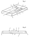
- the light guide according to the invention is shown in perspective at the figure 1 .
- this light guide is generally in the form of a closed loop on itself. It comprises a light injection zone 2 facing which a light source 4 is arranged. Any type of light source such as a filament bulb or a light-emitting diode may be used in the context of the present invention.
- the light is injected into the light guide 1 according to the invention in a substantially rectilinear direction XX.
- the zone 2 for injecting light is extended, via a first semi-cylindrical transmission zone 6, by a zone 8 for extracting light.
- This light extraction zone 8 is provided with a plurality of optical extractors 10 for extracting the light from the light guide 1 and directing it towards the surface of an information display device 12 of the type reflective such as a liquid crystal cell.
- the reflective display device 12 is slid and wrapped inside the loop formed by the light guide 1.
- the display face 14 of the information of the display device 12 is turned on the side of the zone 8 for extracting the light from the light guide 1.
- the light extraction zone 8 is itself extended by a second semi-cylindrical transmission zone 16 which is connected to the light injection zone 2.
- the light from the light source 4 which is not extracted from the light guide 1 at the extraction zone 8 for the illumination of the information display device 12 continues its way to the inside the light guide 1 and returns to its starting point at the area 2 of injection of light.
- the light which is not used at the level of the extraction zone 8 is reinjected into the light guide 1 in the same direction of propagation as the light initially injected by the light source 4 and thus optimally interacts with the light extractors 10, whereby the coupling of the light in the guide 1 is improved and most of the light recovered at the extraction zone 8 is reused.
- the lighting of the display device information 12 is homogeneous over the entire surface thereof and much brighter than with the solutions of the prior art.
- the semi-cylindrical transmission zone 16 is connected to the light injection zone 2 via two connecting sections A and B of substantially triangular shape.
- a triangular shape makes it possible to occupy a maximum surface area between the semi-cylindrical transmission zone 16 and the light injection zone 2 without modifying the parabolic profile of the injection zone 2.
- the triangular shape of the two sections connection A and B also makes it possible to maintain a certain collimation of the light so that the recycled light returns to the zone 8 for extracting the light along propagation directions that are mainly parallel to the longitudinal axis of symmetry of the guide 1.
- the optical behavior of the light guide 1 according to the invention has been studied by means of optical modeling and simulation tools. It was assumed that the light guide 1 was for example made of glass and had a constant thickness of 0.4 mm throughout its length. Of course, the light guide 1 may be made of another transparent dielectric material such as a plastic material or polymethyl methacrylate better known by its acronym PMMA. The radius of curvature of the first and second semi-cylindrical transmission zones 6 and 16 has been chosen equal to 0.95 mm.
- the simulated light source 4 corresponds to a light-emitting diode having a light emission lobe similar to that of light-emitting diodes, especially those marketed by Kingbright. It will be noted that the optical extractors 10 have not been taken into account in the present modeling insofar as the aim is to evaluate the behavior of the part of the light which precisely did not interact with these extractors.
- the above modeling has also found that the luminous flux inside the light guide 1 had good parallelism with propagation directions within a maximum angle of 20 °.
- the injection zone 2 is of parabolic shape, the light source 4 being placed opposite the top 18 of the dish.
- This configuration is such that a majority (about 80%) of the light injected by the light source 4 into the guide 1 undergoes a total reflection inside the guide 1 and can not escape from it. therefore, the reflection of the light is total at the interface between the guide 1 and the ambient air. It is therefore not necessary to resort to artifices such as a metallization of the periphery of the light guide 1 to ensure that the light does not escape the guide 1.
- the parabolic shape of the area of Injection 2 has the effect of collimating the beams of light emitted by the light source 4 in directions of propagation parallel to the axis of symmetry of the parabola which coincides with the direction of injection XX of the light in the guide 1 .
- figure 3 is a view of an alternative embodiment of the light guide 1 according to the invention.
- this is a transmissive type information display device 20.
- the light guide 22 has the same geometry as the light guide 1 illustrated in FIG. figure 2 .
- the zone 24 for extracting the light disposed in the extension of the light injection zone 26, is located beneath the surface of the display device 20, so as to illuminate it by the rear.
- the extraction zone 24 is then extended by a first semi-cylindrical transmission portion 26 itself extended by a second flat transmission portion 28 which closes on the light injection zone 26 via a third semi-transmission portion.
- the first, second and third transmission portions 26, 28 and 30 serve only to reduce the light that has not been used at the extraction zone 24 to the injection zone 26 so as to that it can be reinjected into the guide 22. It will be understood that the display surface 32 of the information display device 20 is oriented upwards, facing the flat transmission portion 28.
Landscapes
- Physics & Mathematics (AREA)
- General Physics & Mathematics (AREA)
- Optics & Photonics (AREA)
- Planar Illumination Modules (AREA)
- Devices For Indicating Variable Information By Combining Individual Elements (AREA)
- Light Guides In General And Applications Therefor (AREA)
Claims (5)
- Beleuchtungssystem einer Informationsanzeigevorrichtung (12; 20), wobei das Beleuchtungssystem einen Lichtleiter (1; 22) mit einem Bereich (2; 26) aufweist, in welchen das von zumindest einer Lichtquelle (4) erzeugte Licht eingekoppelt wird, wobei der Lichtleiter anderweitig einen Auskopplungsbereich (8; 24) für das Licht aufweist, der sich im Inneren des Leiters (1; 22) erstreckt, um die Anzeigevorrichtung (12; 20) zu beleuchten, wobei der Auskopplungsbereich (8; 24), welcher sich in Verlängerung des Einkopplungsbereichs erstreckt, mit Lichtauskopplern (10) versehen ist, wobei der Lichtleiter (1; 22) die Form eines Rings darstellt, welcher sich auf dem Niveau des Einkopplungsbereichs (2; 26) des Lichts selbst schließt, um es dem von der Lichtquelle (4) kommenden und nicht vom Lichtleiter (1; 22) auf dem Niveau des Auskopplungsbereichs (8; 24) extrahierten Licht zu ermöglichen, seinen Weg im Inneren des Lichtleiters (1; 22) fortzusetzen und an seinen Ausgangspunkt auf dem Niveau des Einkopplungsbereichs des Lichts (2; 26) zurückzukehren, dadurch gekennzeichnet, dass der Lichtleiter (1; 22) derart dimensioniert ist, dass die Informationsanzeigevorrichtung (12; 20) im Inneren des Rings angeordnet werden kann, und dass die Lichtauskoppler (10) derart angeordnet sind:(a) um das ausgekoppelte Licht gegen die Informationsanzeigefläche (14) der Informationsanzeigevorrichtung (12) zu richten, wenn diese reflektierend ist und die Informationsanzeigefläche (14) auf den Auskopplungsbereich (8) gerichtet ist, oder(b) um das extrahierte Licht gegen die Rückseite der Informationsanzeigevorrichtung (20) zu richten, die der Informationsanzeigefläche (32) abgewandt ist, wenn diese transmissiv ist und mit ihre Rückseite zum Auskopplungsbereich (24) gerichtet ist.
- Beleuchtungssystem nach Anspruch 1, dadurch gekennzeichnet, dass der Einkopplungsbereich des Lichts (2) über einen ersten halbzylindrischen Transmissionsbereich (6) über den Auskopplungsbereich des Lichts (8) verlängert ist, wobei der Auskopplungsbereich des Lichts (8) selbst über einen zweiten halbzylindrischen Transmissionsbereich (16) verlängert ist, der sich an den Einkopplungsbereich des Lichts (2) anschließt, wobei die Informationsanzeigevorrichtung (1) reflektierend und mit ihrer Informationsanzeigefläche (14) zum Auskopplungsbereich des Lichts (8) des Lichtleiters (1) ausgerichtet ist.
- Beleuchtungssystem nach Anspruch 1, dadurch gekennzeichnet, dass der in Verlängerung des Einkopplungsbereichs des Lichts (26) angeordnete Auskopplungsbereich des Lichts (24) über einen ersten halbzylindrischen Transmissionsabschnitt (26) verlängert ist, der selbst über einen zweiten planaren Transmissionsabschnitt (28) verlängert ist, der sich wieder mit dem Einkopplungsbereich des Lichts (26) über einen dritten halbzylindrischen Transmissionsbereich (30) schließt, wobei der erste, zweite und dritte Transmissionsabschnitt (26, 28, 30) einzig und allein dazu dienen, das Licht zurückzuführen, welches auf dem Niveau des Auskopplungsbereichs (24) bis zum Einkopplungsbereich (26) nicht verwendet wurde, um es wieder in den Leiter (22) einkoppeln zu können, wobei die Informationsanzeigevorrichtung (20) transmissiv ausgebildet und ihre Informationsanzeigefläche (32) zum ebenen Transmissionsabschnitt (28) ausgerichtet ist.
- Beleuchtungssystem nach einem beliebigen der Ansprüche 2 oder 3, dadurch gekennzeichnet, dass sich der zweite halbzylindrische Transmissionsabschnitt (16) und der dritte halbzylindrische Transmissionsabschnitt (30) über zwei im Wesentlichen dreieckige Anschlussbereiche an den Einkopplungsbereich (2) des Lichts anschließen.
- Beleuchtungssystem nach einem beliebigen der Ansprüche 1 bis 4, dadurch gekennzeichnet, dass der Einkopplungsbereich des Lichts (2; 26) ein parabolisches Profil darstellt.
Priority Applications (6)
| Application Number | Priority Date | Filing Date | Title |
|---|---|---|---|
| EP10164825A EP2392952B1 (de) | 2010-06-03 | 2010-06-03 | Beleuchtungssystem eines Informationsanzeigesystems, das einen Lichtwellenleiter umfasst |
| JP2011117732A JP5244215B2 (ja) | 2010-06-03 | 2011-05-26 | 光ガイドを含むデータ・ディスプレイ・デバイス用の照明システム |
| US13/151,052 US8517589B2 (en) | 2010-06-03 | 2011-06-01 | Lighting system for a data display device including a light guide |
| CN201110147552.1A CN102313201B (zh) | 2010-06-03 | 2011-06-02 | 包括光导的数据显示设备的照明系统 |
| KR1020110053155A KR101190474B1 (ko) | 2010-06-03 | 2011-06-02 | 광통로를 포함하는 데이터 디스플레이 장치를 위한 조명 시스템 |
| HK12105473.1A HK1164977A1 (en) | 2010-06-03 | 2012-06-05 | Lighting system for a data display device including a light guide |
Applications Claiming Priority (1)
| Application Number | Priority Date | Filing Date | Title |
|---|---|---|---|
| EP10164825A EP2392952B1 (de) | 2010-06-03 | 2010-06-03 | Beleuchtungssystem eines Informationsanzeigesystems, das einen Lichtwellenleiter umfasst |
Publications (2)
| Publication Number | Publication Date |
|---|---|
| EP2392952A1 EP2392952A1 (de) | 2011-12-07 |
| EP2392952B1 true EP2392952B1 (de) | 2012-12-12 |
Family
ID=42947393
Family Applications (1)
| Application Number | Title | Priority Date | Filing Date |
|---|---|---|---|
| EP10164825A Active EP2392952B1 (de) | 2010-06-03 | 2010-06-03 | Beleuchtungssystem eines Informationsanzeigesystems, das einen Lichtwellenleiter umfasst |
Country Status (6)
| Country | Link |
|---|---|
| US (1) | US8517589B2 (de) |
| EP (1) | EP2392952B1 (de) |
| JP (1) | JP5244215B2 (de) |
| KR (1) | KR101190474B1 (de) |
| CN (1) | CN102313201B (de) |
| HK (1) | HK1164977A1 (de) |
Families Citing this family (2)
| Publication number | Priority date | Publication date | Assignee | Title |
|---|---|---|---|---|
| TWI554866B (zh) * | 2015-10-06 | 2016-10-21 | 宇帷國際股份有限公司 | 電子裝置 |
| TWI602049B (zh) * | 2015-10-06 | 2017-10-11 | 英信科技有限公司 | 電子裝置 |
Family Cites Families (8)
| Publication number | Priority date | Publication date | Assignee | Title |
|---|---|---|---|---|
| JPH09325336A (ja) * | 1996-06-03 | 1997-12-16 | Keiji Iimura | 面状光源装置と面状光源付き受動型表示装置 |
| GB2324599A (en) * | 1997-04-22 | 1998-10-28 | Ford Motor Co | Looped light pipe illuminator for illuminating dials etc. |
| JP2001318235A (ja) * | 2000-05-10 | 2001-11-16 | Bridgestone Corp | 液晶照明装置 |
| JP2003031016A (ja) * | 2001-07-10 | 2003-01-31 | Minolta Co Ltd | 面状照明装置及び画像表示装置 |
| US6874924B1 (en) * | 2002-03-14 | 2005-04-05 | Ilight Technologies, Inc. | Illumination device for simulation of neon lighting |
| JP2009503793A (ja) * | 2005-07-28 | 2009-01-29 | ライト プレスクリプションズ イノベーターズ エルエルシー | バックライトおよびフロントライト用のエテンデュ保存型照明光学部品 |
| JP2009265960A (ja) * | 2008-04-25 | 2009-11-12 | Panasonic Corp | 信号機 |
| WO2009134573A1 (en) * | 2008-04-30 | 2009-11-05 | 3M Innovative Properties Company | Light injection coupler and lighting system including the same |
-
2010
- 2010-06-03 EP EP10164825A patent/EP2392952B1/de active Active
-
2011
- 2011-05-26 JP JP2011117732A patent/JP5244215B2/ja active Active
- 2011-06-01 US US13/151,052 patent/US8517589B2/en active Active
- 2011-06-02 KR KR1020110053155A patent/KR101190474B1/ko not_active IP Right Cessation
- 2011-06-02 CN CN201110147552.1A patent/CN102313201B/zh active Active
-
2012
- 2012-06-05 HK HK12105473.1A patent/HK1164977A1/xx unknown
Also Published As
| Publication number | Publication date |
|---|---|
| US8517589B2 (en) | 2013-08-27 |
| CN102313201B (zh) | 2014-07-09 |
| JP2011253810A (ja) | 2011-12-15 |
| KR101190474B1 (ko) | 2012-10-12 |
| US20110299300A1 (en) | 2011-12-08 |
| KR20110132994A (ko) | 2011-12-09 |
| CN102313201A (zh) | 2012-01-11 |
| JP5244215B2 (ja) | 2013-07-24 |
| EP2392952A1 (de) | 2011-12-07 |
| HK1164977A1 (en) | 2012-09-28 |
Similar Documents
| Publication | Publication Date | Title |
|---|---|---|
| EP2791717B1 (de) | Wellenleiter mit übereinanderliegenden leitelementen und herstellungsverfahren dafür | |
| EP2341375B1 (de) | Vorrichtung zur Bündelung, Homogenisierung und Extraktion von Licht zum Beleuchten einer Anzeigevorrichtung | |
| EP2541291B1 (de) | Lichtwellenleiter mit Entkoppelungsabschnitt, und Strahlenblende, in der die entkoppelten Strahlen gesammelt werden | |
| EP2891007B1 (de) | Optische vorrichtung mit einem lichtwellenleiter und verfahren zur herstellung einer solchen vorrichtung | |
| CH696516A5 (fr) | Instrument portable de mesure d'une grandeur physiologique comprenant un dispositif pour l'illumination de la surface d'un tissu organique. | |
| EP1867913B1 (de) | Vorrichtung zur Beleuchtung oder Signalisierung mittels Lichtwellenleiter für Kraftfahrzeuge | |
| EP0017922B1 (de) | Streuende Oberflächenstruktur für einen Lichtleiter in einer Informationsanzeigevorrichtung | |
| EP2476947A2 (de) | Vorrichtung zur Beleuchtung oder Signalisierung mittels Lichtwellenleiter für Kraftfahrzeug | |
| FR3012624A1 (fr) | Guide optique adapte pour creer deux empreintes lumineuses | |
| FR2782829A1 (fr) | Panneaux d'affichage lumineux | |
| EP1801492A1 (de) | Beleuchtungseinrichtung mit Lichtleitstab für Kraftfahrzeug | |
| EP1826607A1 (de) | Flüssigkristallanzeigeeinrichtung, die farbige Segmente anzeigt und mit einer solchen Einrichtung ausgestattete Uhr | |
| EP2392952B1 (de) | Beleuchtungssystem eines Informationsanzeigesystems, das einen Lichtwellenleiter umfasst | |
| EP3428739B1 (de) | Anzeigeeinheit | |
| EP1479338B1 (de) | Tragbares Gerät zur Erfassung einer physiologischen Messgrösse mit einem Gerät zur Beleuchtung der Oberfläche von organischem Gewebe | |
| CH703287A2 (fr) | Système d'éclairage d'un dispositif d'affichage d'informations comprenant un guide de lumière. | |
| FR3048067A1 (fr) | Guides optiques superposes produisant differents motifs lumineux | |
| EP0499536B1 (de) | Beleuchteter Zeiger | |
| EP3315857B1 (de) | Verbesserter gebogener lichtwellenleiter | |
| EP2828694B1 (de) | System zum einkoppeln von licht in einen wellenleiter, wellenleitervorrichtung und anordnung zum einkoppeln von licht in einen wellenleiter | |
| WO2016030217A1 (fr) | Dispositif d'eclairage a diodes electroluminescentes comportant un eclairage compatible de l'utilisation de jumelles de vision nocturne et comprenant un guide de lumiere | |
| CH702435A2 (fr) | Dispositif de collimation, d'uniformisation et d'extraction de lumière pour l'éclairage d'un dispositif d'affichage. | |
| WO2013010689A1 (fr) | Guide de lumière pour l'éclairage d'un dispositif d'affichage d'informations | |
| CH713977B1 (fr) | Ensemble d'affichage, en particulier pour une pièce d'horlogerie. | |
| FR3105349A1 (fr) | Dispositif d’éclairage et/ou de signalisation comprenant une pluralité d'éléments opaques. |
Legal Events
| Date | Code | Title | Description |
|---|---|---|---|
| AK | Designated contracting states |
Kind code of ref document: A1 Designated state(s): AL AT BE BG CH CY CZ DE DK EE ES FI FR GB GR HR HU IE IS IT LI LT LU LV MC MK MT NL NO PL PT RO SE SI SK SM TR |
|
| AX | Request for extension of the european patent |
Extension state: BA ME RS |
|
| PUAI | Public reference made under article 153(3) epc to a published international application that has entered the european phase |
Free format text: ORIGINAL CODE: 0009012 |
|
| 17P | Request for examination filed |
Effective date: 20120608 |
|
| 17Q | First examination report despatched |
Effective date: 20120711 |
|
| GRAP | Despatch of communication of intention to grant a patent |
Free format text: ORIGINAL CODE: EPIDOSNIGR1 |
|
| GRAS | Grant fee paid |
Free format text: ORIGINAL CODE: EPIDOSNIGR3 |
|
| GRAA | (expected) grant |
Free format text: ORIGINAL CODE: 0009210 |
|
| AK | Designated contracting states |
Kind code of ref document: B1 Designated state(s): AL AT BE BG CH CY CZ DE DK EE ES FI FR GB GR HR HU IE IS IT LI LT LU LV MC MK MT NL NO PL PT RO SE SI SK SM TR |
|
| REG | Reference to a national code |
Ref country code: GB Ref legal event code: FG4D Free format text: NOT ENGLISH |
|
| REG | Reference to a national code |
Ref country code: CH Ref legal event code: EP |
|
| REG | Reference to a national code |
Ref country code: AT Ref legal event code: REF Ref document number: 588565 Country of ref document: AT Kind code of ref document: T Effective date: 20121215 |
|
| REG | Reference to a national code |
Ref country code: CH Ref legal event code: NV Representative=s name: ICB INGENIEURS CONSEILS EN BREVETS SA, CH |
|
| REG | Reference to a national code |
Ref country code: IE Ref legal event code: FG4D Free format text: LANGUAGE OF EP DOCUMENT: FRENCH |
|
| REG | Reference to a national code |
Ref country code: DE Ref legal event code: R096 Ref document number: 602010004053 Country of ref document: DE Effective date: 20130207 |
|
| PG25 | Lapsed in a contracting state [announced via postgrant information from national office to epo] |
Ref country code: FI Free format text: LAPSE BECAUSE OF FAILURE TO SUBMIT A TRANSLATION OF THE DESCRIPTION OR TO PAY THE FEE WITHIN THE PRESCRIBED TIME-LIMIT Effective date: 20121212 Ref country code: LT Free format text: LAPSE BECAUSE OF FAILURE TO SUBMIT A TRANSLATION OF THE DESCRIPTION OR TO PAY THE FEE WITHIN THE PRESCRIBED TIME-LIMIT Effective date: 20121212 Ref country code: ES Free format text: LAPSE BECAUSE OF FAILURE TO SUBMIT A TRANSLATION OF THE DESCRIPTION OR TO PAY THE FEE WITHIN THE PRESCRIBED TIME-LIMIT Effective date: 20130323 Ref country code: SE Free format text: LAPSE BECAUSE OF FAILURE TO SUBMIT A TRANSLATION OF THE DESCRIPTION OR TO PAY THE FEE WITHIN THE PRESCRIBED TIME-LIMIT Effective date: 20121212 Ref country code: NO Free format text: LAPSE BECAUSE OF FAILURE TO SUBMIT A TRANSLATION OF THE DESCRIPTION OR TO PAY THE FEE WITHIN THE PRESCRIBED TIME-LIMIT Effective date: 20130312 Ref country code: HR Free format text: LAPSE BECAUSE OF FAILURE TO SUBMIT A TRANSLATION OF THE DESCRIPTION OR TO PAY THE FEE WITHIN THE PRESCRIBED TIME-LIMIT Effective date: 20121212 |
|
| REG | Reference to a national code |
Ref country code: NL Ref legal event code: VDEP Effective date: 20121212 |
|
| REG | Reference to a national code |
Ref country code: AT Ref legal event code: MK05 Ref document number: 588565 Country of ref document: AT Kind code of ref document: T Effective date: 20121212 |
|
| REG | Reference to a national code |
Ref country code: LT Ref legal event code: MG4D |
|
| PG25 | Lapsed in a contracting state [announced via postgrant information from national office to epo] |
Ref country code: GR Free format text: LAPSE BECAUSE OF FAILURE TO SUBMIT A TRANSLATION OF THE DESCRIPTION OR TO PAY THE FEE WITHIN THE PRESCRIBED TIME-LIMIT Effective date: 20130313 Ref country code: LV Free format text: LAPSE BECAUSE OF FAILURE TO SUBMIT A TRANSLATION OF THE DESCRIPTION OR TO PAY THE FEE WITHIN THE PRESCRIBED TIME-LIMIT Effective date: 20121212 Ref country code: SI Free format text: LAPSE BECAUSE OF FAILURE TO SUBMIT A TRANSLATION OF THE DESCRIPTION OR TO PAY THE FEE WITHIN THE PRESCRIBED TIME-LIMIT Effective date: 20121212 |
|
| PG25 | Lapsed in a contracting state [announced via postgrant information from national office to epo] |
Ref country code: AT Free format text: LAPSE BECAUSE OF FAILURE TO SUBMIT A TRANSLATION OF THE DESCRIPTION OR TO PAY THE FEE WITHIN THE PRESCRIBED TIME-LIMIT Effective date: 20121212 Ref country code: BG Free format text: LAPSE BECAUSE OF FAILURE TO SUBMIT A TRANSLATION OF THE DESCRIPTION OR TO PAY THE FEE WITHIN THE PRESCRIBED TIME-LIMIT Effective date: 20130312 Ref country code: EE Free format text: LAPSE BECAUSE OF FAILURE TO SUBMIT A TRANSLATION OF THE DESCRIPTION OR TO PAY THE FEE WITHIN THE PRESCRIBED TIME-LIMIT Effective date: 20121212 Ref country code: IS Free format text: LAPSE BECAUSE OF FAILURE TO SUBMIT A TRANSLATION OF THE DESCRIPTION OR TO PAY THE FEE WITHIN THE PRESCRIBED TIME-LIMIT Effective date: 20130412 Ref country code: SK Free format text: LAPSE BECAUSE OF FAILURE TO SUBMIT A TRANSLATION OF THE DESCRIPTION OR TO PAY THE FEE WITHIN THE PRESCRIBED TIME-LIMIT Effective date: 20121212 Ref country code: CZ Free format text: LAPSE BECAUSE OF FAILURE TO SUBMIT A TRANSLATION OF THE DESCRIPTION OR TO PAY THE FEE WITHIN THE PRESCRIBED TIME-LIMIT Effective date: 20121212 |
|
| PG25 | Lapsed in a contracting state [announced via postgrant information from national office to epo] |
Ref country code: PT Free format text: LAPSE BECAUSE OF FAILURE TO SUBMIT A TRANSLATION OF THE DESCRIPTION OR TO PAY THE FEE WITHIN THE PRESCRIBED TIME-LIMIT Effective date: 20130412 Ref country code: NL Free format text: LAPSE BECAUSE OF FAILURE TO SUBMIT A TRANSLATION OF THE DESCRIPTION OR TO PAY THE FEE WITHIN THE PRESCRIBED TIME-LIMIT Effective date: 20121212 Ref country code: PL Free format text: LAPSE BECAUSE OF FAILURE TO SUBMIT A TRANSLATION OF THE DESCRIPTION OR TO PAY THE FEE WITHIN THE PRESCRIBED TIME-LIMIT Effective date: 20121212 Ref country code: RO Free format text: LAPSE BECAUSE OF FAILURE TO SUBMIT A TRANSLATION OF THE DESCRIPTION OR TO PAY THE FEE WITHIN THE PRESCRIBED TIME-LIMIT Effective date: 20121212 |
|
| PLBE | No opposition filed within time limit |
Free format text: ORIGINAL CODE: 0009261 |
|
| STAA | Information on the status of an ep patent application or granted ep patent |
Free format text: STATUS: NO OPPOSITION FILED WITHIN TIME LIMIT |
|
| PG25 | Lapsed in a contracting state [announced via postgrant information from national office to epo] |
Ref country code: DK Free format text: LAPSE BECAUSE OF FAILURE TO SUBMIT A TRANSLATION OF THE DESCRIPTION OR TO PAY THE FEE WITHIN THE PRESCRIBED TIME-LIMIT Effective date: 20121212 |
|
| 26N | No opposition filed |
Effective date: 20130913 |
|
| PG25 | Lapsed in a contracting state [announced via postgrant information from national office to epo] |
Ref country code: CY Free format text: LAPSE BECAUSE OF FAILURE TO SUBMIT A TRANSLATION OF THE DESCRIPTION OR TO PAY THE FEE WITHIN THE PRESCRIBED TIME-LIMIT Effective date: 20121212 |
|
| BERE | Be: lapsed |
Owner name: THE SWATCH GROUP RESEARCH AND DEVELOPMENT LTD. Effective date: 20130630 |
|
| PG25 | Lapsed in a contracting state [announced via postgrant information from national office to epo] |
Ref country code: IT Free format text: LAPSE BECAUSE OF FAILURE TO SUBMIT A TRANSLATION OF THE DESCRIPTION OR TO PAY THE FEE WITHIN THE PRESCRIBED TIME-LIMIT Effective date: 20121212 |
|
| REG | Reference to a national code |
Ref country code: DE Ref legal event code: R097 Ref document number: 602010004053 Country of ref document: DE Effective date: 20130913 |
|
| PG25 | Lapsed in a contracting state [announced via postgrant information from national office to epo] |
Ref country code: MC Free format text: LAPSE BECAUSE OF FAILURE TO SUBMIT A TRANSLATION OF THE DESCRIPTION OR TO PAY THE FEE WITHIN THE PRESCRIBED TIME-LIMIT Effective date: 20121212 |
|
| REG | Reference to a national code |
Ref country code: IE Ref legal event code: MM4A |
|
| PG25 | Lapsed in a contracting state [announced via postgrant information from national office to epo] |
Ref country code: BE Free format text: LAPSE BECAUSE OF NON-PAYMENT OF DUE FEES Effective date: 20130630 |
|
| PG25 | Lapsed in a contracting state [announced via postgrant information from national office to epo] |
Ref country code: IE Free format text: LAPSE BECAUSE OF NON-PAYMENT OF DUE FEES Effective date: 20130603 |
|
| GBPC | Gb: european patent ceased through non-payment of renewal fee |
Effective date: 20140603 |
|
| PG25 | Lapsed in a contracting state [announced via postgrant information from national office to epo] |
Ref country code: MT Free format text: LAPSE BECAUSE OF FAILURE TO SUBMIT A TRANSLATION OF THE DESCRIPTION OR TO PAY THE FEE WITHIN THE PRESCRIBED TIME-LIMIT Effective date: 20121212 |
|
| PG25 | Lapsed in a contracting state [announced via postgrant information from national office to epo] |
Ref country code: SM Free format text: LAPSE BECAUSE OF FAILURE TO SUBMIT A TRANSLATION OF THE DESCRIPTION OR TO PAY THE FEE WITHIN THE PRESCRIBED TIME-LIMIT Effective date: 20121212 Ref country code: GB Free format text: LAPSE BECAUSE OF NON-PAYMENT OF DUE FEES Effective date: 20140603 |
|
| PG25 | Lapsed in a contracting state [announced via postgrant information from national office to epo] |
Ref country code: TR Free format text: LAPSE BECAUSE OF FAILURE TO SUBMIT A TRANSLATION OF THE DESCRIPTION OR TO PAY THE FEE WITHIN THE PRESCRIBED TIME-LIMIT Effective date: 20121212 |
|
| PG25 | Lapsed in a contracting state [announced via postgrant information from national office to epo] |
Ref country code: MK Free format text: LAPSE BECAUSE OF FAILURE TO SUBMIT A TRANSLATION OF THE DESCRIPTION OR TO PAY THE FEE WITHIN THE PRESCRIBED TIME-LIMIT Effective date: 20121212 Ref country code: LU Free format text: LAPSE BECAUSE OF NON-PAYMENT OF DUE FEES Effective date: 20130603 Ref country code: HU Free format text: LAPSE BECAUSE OF FAILURE TO SUBMIT A TRANSLATION OF THE DESCRIPTION OR TO PAY THE FEE WITHIN THE PRESCRIBED TIME-LIMIT; INVALID AB INITIO Effective date: 20100603 |
|
| REG | Reference to a national code |
Ref country code: FR Ref legal event code: PLFP Year of fee payment: 7 |
|
| REG | Reference to a national code |
Ref country code: FR Ref legal event code: PLFP Year of fee payment: 8 |
|
| REG | Reference to a national code |
Ref country code: FR Ref legal event code: PLFP Year of fee payment: 9 |
|
| PG25 | Lapsed in a contracting state [announced via postgrant information from national office to epo] |
Ref country code: AL Free format text: LAPSE BECAUSE OF FAILURE TO SUBMIT A TRANSLATION OF THE DESCRIPTION OR TO PAY THE FEE WITHIN THE PRESCRIBED TIME-LIMIT Effective date: 20121212 |
|
| P01 | Opt-out of the competence of the unified patent court (upc) registered |
Effective date: 20230615 |
|
| PGFP | Annual fee paid to national office [announced via postgrant information from national office to epo] |
Ref country code: FR Payment date: 20230523 Year of fee payment: 14 Ref country code: DE Payment date: 20230523 Year of fee payment: 14 |
|
| PGFP | Annual fee paid to national office [announced via postgrant information from national office to epo] |
Ref country code: CH Payment date: 20230702 Year of fee payment: 14 |