EP2392876A1 - Unified system consisting of a condenser, a bottle and an internal heat exchanger - Google Patents
Unified system consisting of a condenser, a bottle and an internal heat exchanger Download PDFInfo
- Publication number
- EP2392876A1 EP2392876A1 EP11004399A EP11004399A EP2392876A1 EP 2392876 A1 EP2392876 A1 EP 2392876A1 EP 11004399 A EP11004399 A EP 11004399A EP 11004399 A EP11004399 A EP 11004399A EP 2392876 A1 EP2392876 A1 EP 2392876A1
- Authority
- EP
- European Patent Office
- Prior art keywords
- heat exchanger
- bottle
- internal heat
- condenser
- refrigerant
- Prior art date
- Legal status (The legal status is an assumption and is not a legal conclusion. Google has not performed a legal analysis and makes no representation as to the accuracy of the status listed.)
- Granted
Links
Images


Classifications
-
- F—MECHANICAL ENGINEERING; LIGHTING; HEATING; WEAPONS; BLASTING
- F25—REFRIGERATION OR COOLING; COMBINED HEATING AND REFRIGERATION SYSTEMS; HEAT PUMP SYSTEMS; MANUFACTURE OR STORAGE OF ICE; LIQUEFACTION SOLIDIFICATION OF GASES
- F25B—REFRIGERATION MACHINES, PLANTS OR SYSTEMS; COMBINED HEATING AND REFRIGERATION SYSTEMS; HEAT PUMP SYSTEMS
- F25B39/00—Evaporators; Condensers
- F25B39/04—Condensers
-
- F—MECHANICAL ENGINEERING; LIGHTING; HEATING; WEAPONS; BLASTING
- F25—REFRIGERATION OR COOLING; COMBINED HEATING AND REFRIGERATION SYSTEMS; HEAT PUMP SYSTEMS; MANUFACTURE OR STORAGE OF ICE; LIQUEFACTION SOLIDIFICATION OF GASES
- F25B—REFRIGERATION MACHINES, PLANTS OR SYSTEMS; COMBINED HEATING AND REFRIGERATION SYSTEMS; HEAT PUMP SYSTEMS
- F25B40/00—Subcoolers, desuperheaters or superheaters
-
- F—MECHANICAL ENGINEERING; LIGHTING; HEATING; WEAPONS; BLASTING
- F25—REFRIGERATION OR COOLING; COMBINED HEATING AND REFRIGERATION SYSTEMS; HEAT PUMP SYSTEMS; MANUFACTURE OR STORAGE OF ICE; LIQUEFACTION SOLIDIFICATION OF GASES
- F25B—REFRIGERATION MACHINES, PLANTS OR SYSTEMS; COMBINED HEATING AND REFRIGERATION SYSTEMS; HEAT PUMP SYSTEMS
- F25B2339/00—Details of evaporators; Details of condensers
- F25B2339/04—Details of condensers
- F25B2339/044—Condensers with an integrated receiver
-
- F—MECHANICAL ENGINEERING; LIGHTING; HEATING; WEAPONS; BLASTING
- F25—REFRIGERATION OR COOLING; COMBINED HEATING AND REFRIGERATION SYSTEMS; HEAT PUMP SYSTEMS; MANUFACTURE OR STORAGE OF ICE; LIQUEFACTION SOLIDIFICATION OF GASES
- F25B—REFRIGERATION MACHINES, PLANTS OR SYSTEMS; COMBINED HEATING AND REFRIGERATION SYSTEMS; HEAT PUMP SYSTEMS
- F25B2500/00—Problems to be solved
- F25B2500/18—Optimization, e.g. high integration of refrigeration components
Landscapes
- Engineering & Computer Science (AREA)
- Physics & Mathematics (AREA)
- Mechanical Engineering (AREA)
- Thermal Sciences (AREA)
- General Engineering & Computer Science (AREA)
- Heat-Exchange Devices With Radiators And Conduit Assemblies (AREA)
- Air-Conditioning For Vehicles (AREA)
Abstract
Description
Le secteur technique de la présente invention est celui des boucles de climatisation autrement appelées boucles ou circuits de réfrigération. L'invention vise un ensemble unitaire constitutif d'une telle boucle.The technical sector of the present invention is that of air conditioning loops otherwise called loops or refrigeration circuits. The invention relates to a unitary unit constituting such a loop.
Une boucle de climatisation est classiquement utilisée sur les véhicules automobiles pour générer un flux d'air chaud ou un flux d'air froid envoyé dans l'habitacle du véhicule. Cette boucle comprend classiquement un condenseur, une bouteille, un organe de détente, un évaporateur et un compresseur parcourus dans cet ordre par un fluide réfrigérant. Le condenseur est un échangeur traversé par un flux d'air extérieur alors que l'évaporateur est un échangeur traversé par le flux d'air intérieur, c'est-à-dire le flux d'air envoyé dans l'habitacle du véhicule automobile. Le fluide réfrigérant qui circule entre une sortie du compresseur et une entrée de l'organe de détente est soumis à haute pression et haute température alors que le fluide réfrigérant qui circule entre la sortie de l'organe de détente et l'entrée du compresseur est soumis à basse pression et basse température.An air conditioning loop is conventionally used on motor vehicles to generate a flow of hot air or a cold air flow sent into the passenger compartment of the vehicle. This loop conventionally comprises a condenser, a bottle, an expansion member, an evaporator and a compressor traversed in this order by a refrigerant fluid. The condenser is an exchanger crossed by an outside air flow while the evaporator is a heat exchanger through which the interior air flow flows, that is to say the flow of air sent into the passenger compartment of the motor vehicle. . The refrigerant fluid that flows between an outlet of the compressor and an inlet of the expansion member is subjected to high pressure and high temperature while the refrigerant fluid circulating between the outlet of the expansion member and the inlet of the compressor is subjected to low pressure and low temperature.
Une telle boucle de climatisation peut être améliorée par l'ajout d'un échangeur de chaleur interne dont la fonction est de créer un échange thermique entre le fluide réfrigérant soumis à haute pression/haute température et le fluide réfrigérant soumis à basse pression/basse température. L'ajout de ce composant améliore le rendement global de la boucle de climatisation.Such an air conditioning loop can be improved by the addition of an internal heat exchanger whose function is to create a heat exchange between the refrigerant fluid subjected to high pressure / high temperature and the refrigerant fluid subjected to low pressure / low temperature . The addition of this component improves the overall efficiency of the air conditioning loop.
Cependant, il s'agit d'un composant supplémentaire à intégrer dans un compartiment moteur du véhicule, ce dernier étant déjà particulièrement encombré.However, it is an additional component to be integrated into an engine compartment of the vehicle, the latter being already particularly congested.
Il est connu du document
La
Il existe donc un besoin pour intégrer astucieusement un tel échangeur de chaleur interne dans une boucle de climatisation comprenant une bouteille.There is therefore a need to cleverly integrate such an internal heat exchanger in an air conditioning loop comprising a bottle.
Le but de la présente invention est donc de proposer une nouvelle architecture de certains composants de la boucle de climatisation en combinant dans un même ensemble unitaire le condenseur, la bouteille et l'échangeur de chaleur interne de sorte à rassembler ces éléments pour mutualiser la circulation du fluide réfrigérant et ainsi gagner en compacité.The object of the present invention is therefore to propose a new architecture of certain components of the air conditioning loop by combining in the same unitary unit the condenser, the bottle and the internal heat exchanger so as to gather these elements to pool the circulation. refrigerant and thus gain compactness.
L'invention a donc pour objet un système comprenant un condenseur, une bouteille et un échangeur de chaleur interne aptes à être parcourus par un fluide réfrigérant, ledit condenseur comprenant un orifice de sortie de fluide réfrigérant raccordée à la bouteille, ladite bouteille comprenant un passage de fluide réfrigérant vers à destination de l'échangeur de chaleur interne caractérisé en ce que le condenseur, la bouteille et l'échangeur de chaleur interne sont aptes à être parcourus dans cet ordre par le fluide réfrigérant et sont rassemblés de manière unitaire.The invention therefore relates to a system comprising a condenser, a bottle and an internal heat exchanger adapted to be traversed by a refrigerant, said condenser comprising a coolant outlet orifice connected to the bottle, said bottle comprising a passage refrigerant fluid towards the internal heat exchanger characterized in that the condenser, the bottle and the internal heat exchanger are able to be traversed in this order by the refrigerant and are unitarily collected.
Selon une première caractéristique de l'invention, un organe de détente destiné à détendre le fluide réfrigérant comprend un second canal raccordé à une sortie dudit système, ledit organe de détente faisant partie de l'ensemble unitaire.According to a first characteristic of the invention, a detent intended to relax the refrigerant fluid comprises a second channel connected to an output of said system, said detent member being part of the unitary unit.
Selon une deuxième caractéristique de l'invention, l'échangeur de chaleur interne est solidaire du condenseur alors que l'organe de détente est solidaire de l'échangeur de chaleur interne. On entend par solidaire le fait que les pièces concernées sont fixées l'une sur l'autre par des moyens de fixation amovibles ou non amovibles de telle sorte qu'une fois assemblées, il n'existe pas de mouvement relatif d'une pièce par rapport à l'autre.According to a second characteristic of the invention, the internal heat exchanger is integral with the condenser while the expansion member is integral with the internal heat exchanger. Solidarity means that the parts concerned are fixed to one another by removable or non-removable fastening means so that once assembled, there is no relative movement of a part by report to the other.
Selon une autre caractéristique de l'invention, le condenseur présente un faisceau apte à être traversé par un flux d'air, un premier flanc bordant ledit faisceau et un deuxième flanc bordant ledit faisceau en étant opposé au premier flanc par rapport au faisceau, et dans lequel l'échangeur de chaleur interne est solidarisé au premier flanc alors que la bouteille est solidarisée au deuxième flanc. On comprend donc que le faisceau est placé entre le premier et le deuxième flanc, et par conséquent entre l'échangeur de chaleur interne et la bouteille.According to another characteristic of the invention, the condenser has a beam capable of being traversed by an air flow, a first flank bordering said beam and a second flank bordering said beam being opposite to the first flank with respect to the beam, and wherein the internal heat exchanger is secured to the first side while the bottle is secured to the second sidewall. It is therefore understood that the beam is placed between the first and the second sidewall, and therefore between the internal heat exchanger and the bottle.
Selon encore une caractéristique de l'invention, un conduit parcourt le faisceau en reliant ledit passage de la bouteille à l'échangeur de chaleur interne, et plus particulièrement à des canaux haute pression constitutifs de l'échangeur de chaleur interne.According to another characteristic of the invention, a conduit travels the beam by connecting said passage of the bottle to the internal heat exchanger, and more particularly to the high pressure channels constituting the internal heat exchanger.
Selon encore une autre variante de l'invention, la bouteille est solidarisée au deuxième flanc et l'échangeur de chaleur interne s'étend du premier flanc jusqu'au deuxième flanc dans le prolongement du faisceau.According to yet another variant of the invention, the bottle is secured to the second sidewall and the internal heat exchanger extends from the first sidewall to the second sidewall in the extension of the beam.
Selon encore une autre variante de l'invention, l'échangeur de chaleur interne et la bouteille sont solidarisés ou fixés ou montés côté deuxième flanc.According to yet another variant of the invention, the internal heat exchanger and the bottle are secured or fixed or mounted on the second sidewall.
Avantageusement, l'échangeur de chaleur interne est solidarisé sur ladite bouteille. Dans ce cas, l'échangeur de chaleur interne n'est pas en contact avec le condenseur.Advantageously, the internal heat exchanger is secured to said bottle. In this case, the internal heat exchanger is not in contact with the condenser.
Avantageusement encore, la bouteille comprend un dessicant et un filtre.Advantageously, the bottle comprises a desiccant and a filter.
Selon une caractéristique de l'invention, le système comprend un orifice d'entrée haute pression, une sortie, un orifice de sortie basse pression et un orifice d'entrée basse pression, qui sont côté premier flanc du faisceau. L'orifice d'entrée haute pression est destiné à recevoir un fluide réfrigérant soumis à haute pression et haute température en provenance de la boucle de climatisation, plus particulièrement en provenance d'un compresseur. L'orifice de sortie basse pression est destiné à fournir à la boucle de climatisation, et plus particulièrement au compresseur, le fluide réfrigérant soumis à basse pression et basse température. L'orifice d'entrée basse pression est destiné à recevoir le fluide réfrigérant soumis à basse pression et basse température en provenance de la boucle de climatisation, en particulier en provenance d'un évaporateur. Enfin, la sortie est destinée à fournir le fluide réfrigérant soumis à haute pression et haute température à un détendeur constitutif de la boucle de climatisation.According to one characteristic of the invention, the system comprises a high pressure inlet orifice, an outlet, a low pressure outlet orifice and a Low pressure inlet port, which are on the first side of the beam. The high pressure inlet port is adapted to receive a refrigerant fluid subjected to high pressure and high temperature from the air conditioning loop, more particularly from a compressor. The low pressure outlet is intended to provide the air conditioning loop, and more particularly the compressor, the refrigerant fluid subjected to low pressure and low temperature. The low pressure inlet port is intended to receive the refrigerant fluid subjected to low pressure and low temperature from the air conditioning loop, in particular from an evaporator. Finally, the outlet is intended to supply the refrigerant fluid subjected to high pressure and high temperature to a regulator constituting the air conditioning loop.
Selon une alternative de l'invention, le système comprend un orifice d'entrée haute pression côté premier flanc du faisceau et la sortie, l'orifice de sortie basse pression et l'orifice d'entrée basse pression sont côté deuxième flanc du faisceau.According to an alternative of the invention, the system comprises a high-pressure inlet port on the first side of the bundle and the outlet, the low-pressure outlet orifice and the low-pressure inlet orifice are on the second side of the bundle.
Enfin, l'invention couvre une boucle de climatisation parcourue par un fluide réfrigérant et comprenant un compresseur, un organe de détente, un évaporateur et un système selon l'une des caractéristiques énoncées précédemment.Finally, the invention covers an air conditioning loop traversed by a refrigerant fluid and comprising a compressor, an expansion member, an evaporator and a system according to one of the characteristics set out above.
Un tout premier avantage selon l'invention réside dans la possibilité d'intégrer aisément un échangeur de chaleur interne dans une boucle de climatisation utilisant une bouteille localisée entre le condenseur et l'organe de détente. Le caractère unitaire et monobloc facilite l'intégration de ces composants dans le compartiment moteur du véhicule en évitant la multiplication de supports, de conduites et de dispositifs d'étanchéité entre ces composants.A first advantage of the invention lies in the ability to easily integrate an internal heat exchanger in an air conditioning loop using a bottle located between the condenser and the expansion member. The unitary and one-piece character facilitates the integration of these components in the engine compartment of the vehicle by avoiding the multiplication of supports, pipes and sealing devices between these components.
Un autre avantage non négligeable réside dans le bénéfice en compacité, en particulier en termes dimensionnels, que l'ensemble unitaire offre en rassemblant en un même point, autrement dit sur un même support, trois composants de la boucle de climatisation.Another significant advantage lies in the compactness advantage, especially in dimensional terms, that the unitary unit offers by gathering in a single point, in other words on the same support, three components of the air conditioning loop.
D'autres caractéristiques, détails et avantages de l'invention ressortiront plus clairement à la lecture de la description donnée ci-après à titre indicatif en relation avec des dessins dans lesquels :
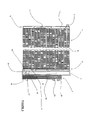
- la
figure 1 est une vue en coupe d'une première variante du système selon l'invention, - la
figure 2 est une vue en coupe de l'échangeur de chaleur interne selon l'invention, - la
figure 3 est une vue en coupe partielle d'une zone particulière du système selon la première variante, - la
figure 4 est une vue en coupe d'une deuxième variante du système selon l'invention, - la
figure 5 est une vue en coupe d'une troisième variante du système selon l'invention, - la
figure 6 est une vue en coupe d'une quatrième variante du système selon l'invention, - la
figure 7 est une vue en coupe d'une cinquième variante du système selon l'invention, - la
figure 8 est une vue en coupe d'une sixième variante du système selon l'invention, - la
figure 9 illustre un accumulateur, - la
figure 10 illustre une bouteille.
- the
figure 1 is a sectional view of a first variant of the system according to the invention, - the
figure 2 is a sectional view of the internal heat exchanger according to the invention, - the
figure 3 is a partial sectional view of a particular zone of the system according to the first variant, - the
figure 4 is a sectional view of a second variant of the system according to the invention, - the
figure 5 is a sectional view of a third variant of the system according to the invention, - the
figure 6 is a sectional view of a fourth variant of the system according to the invention, - the
figure 7 is a sectional view of a fifth variant of the system according to the invention, - the
figure 8 is a sectional view of a sixth variant of the system according to the invention, - the
figure 9 illustrates an accumulator, - the
figure 10 illustrates a bottle.
Il faut noter que les figures exposent l'invention de manière détaillée et suffisante pour sa mise en oeuvre, lesdites figures pouvant bien entendu servir à mieux définir l'invention le cas échéant.It should be noted that the figures disclose the invention in detail and sufficient for its implementation, said figures can of course be used to better define the invention where appropriate.
La
Le condenseur 1 comprend un faisceau 6 traversé par un flux d'air extérieur au véhicule. Ce faisceau comprend une multiplicité de tubes plats 11 qui s'étendent transversalement par rapport au flux d'air extérieur. Ces tubes plats 11 transportent le fluide réfrigérant 4 entre une première boîte collectrice 13 et une seconde boîte collectrice 14. Ces boîtes collectrices 13 et 14 sont donc raccordées fluidiquement avec chaque tube plat 11 et sont partitionnées en chambre de distribution du fluide réfrigérant dans des groupes de tubes plats formant ainsi des passes 7, 8 et 9 de circulation du fluide réfrigérant. La partition des boîtes collectrices est opérée au moyen de séparateurs 15 installés dans le travers de la boîte collectrice de sorte à imposer la circulation du fluide réfrigérant dans la passe concernée.The
Dans le cas d'espèce, le faisceau 6 est divisé en trois passes, la passe supérieure 7 comprenant 5 tubes plats, la passe intermédiaire 8 comprenant 6 tubes plats et la passe inférieure 9 comprenant 4 tubes plats.In the case in point, the
Entre chaque tube plat 11 est installé une intercalaire ou ailette 12 dont la fonction est d'augmenter la surface d'échange thermique entre le fluide réfrigérant et le flux d'air extérieur.Between each
Ces boîtes collectrices 13, 14 forment donc respectivement un premier flanc 10 du faisceau 6 et un deuxième flanc 16 bordant le faisceau et opposé au premier flanc 10 par rapport au faisceau 6.These
Le fluide réfrigérant 4 pénètre dans le système par un orifice d'entrée haute pression 5 du condenseur 1, cette orifice d'entrée 5 étant plus particulièrement installé sur la paroi de la première boîte collectrice 13 et dans la partie supérieure de cette dernière.The
Une bouteille 2 est accolée au deuxième flanc 16. A titre d'exemple, la bouteille 2 et la boîte collectrice 14 peuvent partager une même paroi 19 qui délimite ainsi de manière commune le volume interne de la bouteille 2 et le volume interne de la boîte collectrice 14.A
Cette bouteille prend la forme d'un tube qui s'étend sur toute la hauteur du faisceau 6 et à l'intérieur duquel est installé un déssicant 17 et un filtre 18. Le déssicant 17 a pour fonction de capter les particules d'eau circulant dans le fluide réfrigérant 4 alors que le filtre 18 capte les particules solides qui circulent dans le fluide réfrigérant et qui résultent de l'usure des composants de la boucle de climatisation. Le filtre 18 est placé dans la partie inférieure de la bouteille 2 et ferme complètement le volume interne de la bouteille 2 de sorte à être constamment traversé par le fluide réfrigérant. Ce faisant, le filtre 18 délimite avec la paroi de la bouteille une chambre inférieure 29.This bottle takes the form of a tube which extends over the entire height of the
La paroi 19 présente un orifice de sortie 20 du condenseur qui permet au fluide réfrigérant de circuler de la passe inférieure 9 vers le volume interne de la bouteille 2.The
Le premier flanc 10, et plus particulièrement la paroi délimitant la première boîte collectrice 13, supporte l'échangeur de chaleur interne 3. Ce dernier est délimité par une enveloppe externe 21 dont une face 22 est commune avec la première boîte collectrice 13. Alternativement, l'enveloppe externe 21 peut être soudée sur la paroi qui délimite la première boîte collectrice 13.The
A l'intérieur de l'enveloppe externe 21, des canaux haute pression 24 et des canaux basse pression 23 permettent un échange thermique entre le fluide réfrigérant soumis à haute pression et haute température et ce même fluide réfrigérant soumis à basse pression et basse température. Les canaux haute pression 24 sont reliés à une sortie 25, cette dernière étant dans la première variante de l'invention un orifice de sortie haute pression du système.Inside the
L'échangeur de chaleur interne 3 comprend également un orifice d'entrée basse pression 26 et un orifice de sortie basse pression 27 qui communiquent chacun avec une extrémité des canaux basse pression 23.The
Le système selon l'invention comprend encore un conduit 28 qui s'étend dans le faisceau 6 du premier flanc 13 au deuxième flanc 14. Dans l'exemple de la
Dans cette première variante de l'invention, l'orifice d'entrée haute pression 5, l'orifice d'entrée basse pression 26, l'orifice de sortie basse pression 27 et la sortie 25 sont installés côté premier flanc 10 du faisceau 6. Autrement dit, tous ces moyens de communication vers l'extérieur du système sont placés d'un seul et même côté ce qui facilite l'intégration dans le compartiment moteur du véhicule et évite des cheminements de conduits rendus inutile grâce à l'invention.In this first variant of the invention, the high
Le système est unitaire en ce sens que le condenseur 1, la bouteille 2 et l'échangeur de chaleur interne 3 forme un unique ensemble. Ceci est rendu possible par exemple quand ces composants sont rassemblés par des moyens de solidarisation comme le vissage ou le soudage.The system is unitary in that the
Dans cette première variante de l'invention, les composants sont côte à côte selon l'ordre suivant de gauche à droite en regardant la
Le sens de circulation du fluide réfrigérant 4 à l'intérieur du système prend une importance. Le fluide réfrigérant 4 pénètre dans le système par l'orifice d'entrée haute pression 5 puis circule dans un premier sens dans la passe supérieure 7. La deuxième boîte collectrice 14 collecte ce fluide réfrigérant et le canalise vers la passe intermédiaire 8 où le fluide réfrigérant circule en sens opposé au sens de circulation dans la première passe 7. La première boîte collectrice 13 collecte alors le fluide réfrigérant et le canalise vers la passe inférieure 9 où le fluide circule dans le même sens que le sens de circulation dans la passe supérieure 7. Finalement, la deuxième boîte collectrice 14 collecte le fluide réfrigérant 4 qui passe alors au travers de l'orifice de sortie 20 du condenseur 1, où il pénètre dans la bouteille 2. Pendant ce parcours, le fluide réfrigérant 4 échange thermiquement avec le flux d'air extérieur qui passe au travers du faisceau 6 selon une direction perpendiculaire au plan de la
Le fluide réfrigérant ainsi refroidit passe au travers du déssicant 17 puis au travers du filtre 18 pour atteindre la chambre inférieure 29 de la bouteille 2. A ce stade, le fluide réfrigérant 4 circule dans le conduit 28 selon la direction du faisceau 6 et dans le sens deuxième flanc 16 vers le premier flanc 10. Puis, le fluide réfrigérant 4 pénètre dans l'échangeur de chaleur interne 3, particulièrement dans les canaux haute pression 24. Le fluide réfrigérant à haute pression et haute température remonte alors l'échangeur de chaleur interne pour sortir par la sortie 25. En parallèle, le fluide réfrigérant 4 soumis à basse pression et basse température pénètre dans l'échangeur de chaleur interne 3 par l'orifice d'entrée basse pression 26 puis parcours les canaux basse pression 23 vers le bas pour sortir par l'orifice de sortie basse pression 27. On comprend ici que la circulation du fluide réfrigérant dans l'échangeur interne 3 est à contre-courant, le sens de circulation du fluide circulant dans les canaux haute pression 24 et dans les canaux basse pression 23 étant opposé.The coolant thus cooled passes through the
La
Ces canaux sont alternés. Autrement dit, un canal haute pression 24 côtoie de chaque côté un canal basse pression 23. On notera que les canaux haute pression sont subdivisés en sous-canaux 24a à 241, des parois de subdivision 30 assurant la séparation entre les sous-canaux 24a à 241 tout en garantissant la tenue mécanique du canal haute pression 24 soumis au fluide réfrigérant à haute pression et haute température.These channels are alternated. In other words, a
La
L'enveloppe externe 21 présente un trou au travers duquel le conduit 28 passe, ce dernier étant raccordé aux canaux haute pression 24 en passant au travers du premier canal basse pression 23. Bien entendu, une chambre de répartition raccorde d'un côté l'extrémité du conduit 28 avec l'ensemble des canaux haute pression 24 de sorte à les alimenter simultanément en fluide réfrigérant 4.The
La
La description de la
Dans cette deuxième variante, les composants sont côte à côte selon l'ordre suivant de gauche à droite en regardant la
La
Selon cette troisième variante, l'échangeur de chaleur interne 3 est installé du même côté que la bouteille 2, c'est-à-dire du côté du deuxième flanc 16 bordant le faisceau 6 du condenseur 1. L'échangeur de chaleur interne 3 partage une face 35 de son enveloppe externe 21 avec la bouteille 2. Cette face 35 est donc commune à la bouteille 2 et à l'échangeur de chaleur interne 3. Cette face 35 comprend un passage 34 qui met en communication la chambre inférieure 29 de la bouteille 2 avec les canaux haute pression 24 de l'échangeur de chaleur interne 3. Ce passage 34 est pratiqué sous le filtre 18.According to this third variant, the
Dans cette variante, l'orifice d'entrée haute pression 5 est donc du côté du premier flanc 10 en étant solidarisé sur la première boîte collectrice 13 alors l'orifice d'entrée basse pression 26, la sortie 25 et l'orifice de sortie basse pression 27 sont localisés du côté du deuxième flanc 16.In this variant, the high
Dans cette troisième variante, les composants sont côte à côte selon l'ordre suivant de gauche à droite en regardant la
La
Dans cette variante, les composants sont côte à côte selon l'ordre suivant de gauche à droite en regardant la
La
L'échangeur de chaleur interne 3 est installé dans le plan du faisceau 6 du condenseur 3 mais sous la passe inférieure 9. On comprend donc que l'échangeur de chaleur interne 3 s'étend du premier flanc 10 jusqu'au deuxième flanc 16 bordant de part et d'autre le faisceau 6. Le passage 34 qui met en communication la chambre inférieure 29 de la bouteille 2 avec les canaux haute pression 24 est formé dans la paroi 19 qui est commune à la bouteille 2 et à la deuxième boîte collectrice 14.The
L'enveloppe externe 21 de l'échangeur de chaleur interne 3 est ici accolée sur le faisceau 6, la face 35 de cette enveloppe étant contre la dernière ailette 12 du faisceau 6. Cette enveloppe externe 21 débouche du premier flanc 10 en formant une extrémité 36 sur laquelle sont fabriqués certains des orifices de raccordements.The
Cette extrémité 36 présente une face inférieure de laquelle débouche l'orifice de sortie basse pression 27 et une face supérieure 38, opposée à la face inférieure 37 par rapport à l'échangeur de chaleur interne 3, dont débouchent la sortie 25 et l'orifice d'entrée basse pression 26.This
Dans cette variante, la circulation du fluide réfrigérant dans les canaux basse pression 23 de l'échangeur s'effectue de l'orifice d'entrée basse pression 26 vers le deuxième flanc 16 bordant le faisceau puis revient en sens inverse en direction de l'extrémité 36 pour sortir par l'orifice de sortie basse pression 27. Il n'en va pas de même pour la circulation du fluide réfrigérant soumis à haute pression/haute température qui pénètre dans les canaux haute pression 24 après avoir traversé le passage 34 et circule du deuxième flanc 16 vers le premier flanc 10 pour sortir par la sortie 25. Alors que le fluide réfrigérant soumis à basse pression/basse température circule en « U » dans l'échangeur de chaleur interne, le fluide réfrigérant soumis à haute pression/haute température circule dans cet échangeur selon un « I ».In this variant, the circulation of the refrigerant fluid in the low-
La sixième variante de l'invention est représentée sur la
Cet organe de détente 31 est solidarisé sur la face supérieure 38 de l'extrémité 36 constitutive de l'échangeur de chaleur interne 3.This
Dans la cinquième et la sixième variantes de l'invention, le fluide réfrigérant 4 pénètre le système par l'orifice d'entrée haute pression 5, parcourt les trois passes 7, 8 et 9 puis débouche dans la bouteille 2 solidarisée sur le flanc opposé au flanc qui comporte l'orifice d'entrée haute pression 5. Le fluide réfrigérant passe alors au travers de la bouteille 2 puis pénètre dans l'échangeur de chaleur interne 3 par le passage 34. Le fluide réfrigérant circule ensuite au travers des canaux haute pression 24 du deuxième flanc 16 vers le premier flanc 10 puis sort de l'échangeur de chaleur interne par l'extrémité 36 à travers a sortie 25. Dans le cas de la
Après passage dans l'évaporateur, le fluide réfrigérant 4 entre à basse pression et basse température dans l'organe de détente 31 par le premier canal 32 puis circule dans les canaux basse pression 23 pour finalement sortir du système par l'orifice de sortie basse pression 27 et circuler en direction du compresseur.After passing through the evaporator, the
Claims (12)
Applications Claiming Priority (1)
| Application Number | Priority Date | Filing Date | Title |
|---|---|---|---|
| FR1002388A FR2960950B1 (en) | 2010-06-07 | 2010-06-07 | UNITARY SYSTEM COMPRISING A CONDENSER, A BOTTLE AND AN INTERNAL HEAT EXCHANGER |
Publications (2)
| Publication Number | Publication Date |
|---|---|
| EP2392876A1 true EP2392876A1 (en) | 2011-12-07 |
| EP2392876B1 EP2392876B1 (en) | 2017-12-20 |
Family
ID=43734262
Family Applications (1)
| Application Number | Title | Priority Date | Filing Date |
|---|---|---|---|
| EP11004399.9A Active EP2392876B1 (en) | 2010-06-07 | 2011-05-30 | Unified system comprising of a condenser, a bottle and an internal heat exchanger |
Country Status (2)
| Country | Link |
|---|---|
| EP (1) | EP2392876B1 (en) |
| FR (1) | FR2960950B1 (en) |
Cited By (1)
| Publication number | Priority date | Publication date | Assignee | Title |
|---|---|---|---|---|
| FR3063136A1 (en) * | 2017-02-23 | 2018-08-24 | Valeo Systemes Thermiques | HEAT EXCHANGE DEVICE AND CORRESPONDING AIR CONDITIONING CIRCUIT |
Citations (7)
| Publication number | Priority date | Publication date | Assignee | Title |
|---|---|---|---|---|
| DE19830757A1 (en) * | 1998-07-09 | 2000-01-13 | Behr Gmbh & Co | Air conditioning system especially for a motor vehicle |
| FR2802291A1 (en) * | 1999-12-09 | 2001-06-15 | Valeo Climatisation | AIR CONDITIONING CIRCUIT, PARTICULARLY FOR MOTOR VEHICLE |
| US6539746B1 (en) | 1999-04-23 | 2003-04-01 | Valeo Klimatechnik Gmbh | High pressure gas cooler for a refrigerant circuit of a motor-vehicle air-conditioning system |
| JP2004190956A (en) * | 2002-12-11 | 2004-07-08 | Calsonic Kansei Corp | Condenser |
| EP1512932A2 (en) * | 2003-09-03 | 2005-03-09 | Delphi Technologies, Inc. | Multi-function condenser |
| WO2009068547A1 (en) * | 2007-11-29 | 2009-06-04 | Valeo Systemes Thermiques | Air-conditioning circuit condenser with an undercooling part |
| EP2078906A2 (en) * | 2008-01-11 | 2009-07-15 | Calsonic Kansei Corporation | Condenser for use in vehicle |
-
2010
- 2010-06-07 FR FR1002388A patent/FR2960950B1/en not_active Expired - Fee Related
-
2011
- 2011-05-30 EP EP11004399.9A patent/EP2392876B1/en active Active
Patent Citations (7)
| Publication number | Priority date | Publication date | Assignee | Title |
|---|---|---|---|---|
| DE19830757A1 (en) * | 1998-07-09 | 2000-01-13 | Behr Gmbh & Co | Air conditioning system especially for a motor vehicle |
| US6539746B1 (en) | 1999-04-23 | 2003-04-01 | Valeo Klimatechnik Gmbh | High pressure gas cooler for a refrigerant circuit of a motor-vehicle air-conditioning system |
| FR2802291A1 (en) * | 1999-12-09 | 2001-06-15 | Valeo Climatisation | AIR CONDITIONING CIRCUIT, PARTICULARLY FOR MOTOR VEHICLE |
| JP2004190956A (en) * | 2002-12-11 | 2004-07-08 | Calsonic Kansei Corp | Condenser |
| EP1512932A2 (en) * | 2003-09-03 | 2005-03-09 | Delphi Technologies, Inc. | Multi-function condenser |
| WO2009068547A1 (en) * | 2007-11-29 | 2009-06-04 | Valeo Systemes Thermiques | Air-conditioning circuit condenser with an undercooling part |
| EP2078906A2 (en) * | 2008-01-11 | 2009-07-15 | Calsonic Kansei Corporation | Condenser for use in vehicle |
Cited By (2)
| Publication number | Priority date | Publication date | Assignee | Title |
|---|---|---|---|---|
| FR3063136A1 (en) * | 2017-02-23 | 2018-08-24 | Valeo Systemes Thermiques | HEAT EXCHANGE DEVICE AND CORRESPONDING AIR CONDITIONING CIRCUIT |
| WO2018154250A1 (en) * | 2017-02-23 | 2018-08-30 | Valeo Systemes Thermiques | Heat-exchanging device and associated air-conditioning system |
Also Published As
| Publication number | Publication date |
|---|---|
| FR2960950A1 (en) | 2011-12-09 |
| EP2392876B1 (en) | 2017-12-20 |
| FR2960950B1 (en) | 2013-12-06 |
Similar Documents
| Publication | Publication Date | Title |
|---|---|---|
| EP1068967B1 (en) | Heating-air conditioning device for a motor vehicle | |
| EP1992891B1 (en) | Condenser, in particular for an automobile air-conditioning circuit, and circuit comprising such a condenser | |
| EP2252845B1 (en) | Air-conditioning circuit condenser with an undercooling part | |
| EP1620637B1 (en) | System for cooling a piece of equipment to a low temperature, such as a piece of motor vehicle equipment, and associated heat exchangers | |
| EP0415840A1 (en) | Condenser with receiver/subcooler | |
| FR2977306A1 (en) | HEAT EXCHANGER, IN PARTICULAR FOR MOTOR VEHICLE | |
| FR2947041A1 (en) | Condenser for air-conditioning circuit of motor vehicle, has heat exchanging parts formed by two series of plates stacked in stacking direction, and fluid reserve formed partly by cavity that is directly formed in stack of plates | |
| FR2846736A1 (en) | Stacked plate heat exchanger for motor vehicle air conditioning has separating wall to define separate heat exchange sections which can be selectively communicated for multiple stage operation | |
| FR2962199A1 (en) | CONDENSER, IN PARTICULAR FOR AIR CONDITIONING SYSTEM OF A MOTOR VEHICLE. | |
| FR2912811A1 (en) | High pressure heat exchanger for motor vehicle, has collecting boxes collecting fluid circulating in plane tubes, and separation wall with recess to authorize passage of another fluid on both sides of wall between rows of two of tubes | |
| EP2199709B1 (en) | Device comprising an internal heat exchanger and an accumulator | |
| EP2392876B1 (en) | Unified system comprising of a condenser, a bottle and an internal heat exchanger | |
| FR2935475A1 (en) | Heat exchanger i.e. cooler, for cooling re-circulated exhaust gas, in cooling circuit of heat engine of motor vehicle, has fluid inlets for inletting fractions of coolant, and fluid outlet for evacuating fractions of coolant at same time | |
| EP2392877B1 (en) | Unified system consisting of a condenser, an internal heat exchanger and a bottle | |
| EP2350542B1 (en) | Air-conditioning circuit condenser with internal heat exchanger | |
| EP2372288B1 (en) | Heat exchanger for air conditioning device with reduced ends | |
| EP2912397A1 (en) | Header box for heat exchanger, notably motor vehicle engine charge air cooler | |
| FR3126647A1 (en) | HEAT TREATMENT MODULE WITH EXPANSION MECHANISM | |
| FR3126766A1 (en) | HEAT EXCHANGER OF A REFRIGERANT LOOP. | |
| WO2023030791A1 (en) | Heat exchanger for a coolant loop | |
| FR3060107B1 (en) | HEAT EXCHANGER, ESPECIALLY A MOTOR VEHICLE MOTOR EXHAUST AIR COOLER | |
| FR3133432A1 (en) | Common plate of a thermal module of a refrigerant circuit | |
| FR3126648A1 (en) | Heat treatment module with storage device | |
| EP2743108B1 (en) | Air-conditioning circuit, in particular for motor vehicle | |
| FR2995670A3 (en) | Heat exchanger for exchanging heat between functional fluid of e.g. electrically driven car and air, has distribution elements directing cooling liquid and refrigerant fluid towards collecting elements and crossed by air flows, respectively |
Legal Events
| Date | Code | Title | Description |
|---|---|---|---|
| AK | Designated contracting states |
Kind code of ref document: A1 Designated state(s): AL AT BE BG CH CY CZ DE DK EE ES FI FR GB GR HR HU IE IS IT LI LT LU LV MC MK MT NL NO PL PT RO RS SE SI SK SM TR |
|
| AX | Request for extension of the european patent |
Extension state: BA ME |
|
| PUAI | Public reference made under article 153(3) epc to a published international application that has entered the european phase |
Free format text: ORIGINAL CODE: 0009012 |
|
| 17P | Request for examination filed |
Effective date: 20120608 |
|
| GRAP | Despatch of communication of intention to grant a patent |
Free format text: ORIGINAL CODE: EPIDOSNIGR1 |
|
| INTG | Intention to grant announced |
Effective date: 20170504 |
|
| GRAS | Grant fee paid |
Free format text: ORIGINAL CODE: EPIDOSNIGR3 |
|
| GRAJ | Information related to disapproval of communication of intention to grant by the applicant or resumption of examination proceedings by the epo deleted |
Free format text: ORIGINAL CODE: EPIDOSDIGR1 |
|
| GRAL | Information related to payment of fee for publishing/printing deleted |
Free format text: ORIGINAL CODE: EPIDOSDIGR3 |
|
| GRAP | Despatch of communication of intention to grant a patent |
Free format text: ORIGINAL CODE: EPIDOSNIGR1 |
|
| INTC | Intention to grant announced (deleted) | ||
| INTG | Intention to grant announced |
Effective date: 20171010 |
|
| GRAF | Information related to payment of grant fee modified |
Free format text: ORIGINAL CODE: EPIDOSCIGR3 |
|
| RIN1 | Information on inventor provided before grant (corrected) |
Inventor name: LIU, JIN-MING Inventor name: KARL, STEFAN |
|
| GRAA | (expected) grant |
Free format text: ORIGINAL CODE: 0009210 |
|
| AK | Designated contracting states |
Kind code of ref document: B1 Designated state(s): AL AT BE BG CH CY CZ DE DK EE ES FI FR GB GR HR HU IE IS IT LI LT LU LV MC MK MT NL NO PL PT RO RS SE SI SK SM TR |
|
| REG | Reference to a national code |
Ref country code: GB Ref legal event code: FG4D Free format text: NOT ENGLISH |
|
| REG | Reference to a national code |
Ref country code: CH Ref legal event code: EP |
|
| REG | Reference to a national code |
Ref country code: IE Ref legal event code: FG4D Free format text: LANGUAGE OF EP DOCUMENT: FRENCH |
|
| REG | Reference to a national code |
Ref country code: AT Ref legal event code: REF Ref document number: 956732 Country of ref document: AT Kind code of ref document: T Effective date: 20180115 |
|
| REG | Reference to a national code |
Ref country code: DE Ref legal event code: R096 Ref document number: 602011044285 Country of ref document: DE |
|
| REG | Reference to a national code |
Ref country code: NL Ref legal event code: MP Effective date: 20171220 |
|
| PG25 | Lapsed in a contracting state [announced via postgrant information from national office to epo] |
Ref country code: FI Free format text: LAPSE BECAUSE OF FAILURE TO SUBMIT A TRANSLATION OF THE DESCRIPTION OR TO PAY THE FEE WITHIN THE PRESCRIBED TIME-LIMIT Effective date: 20171220 Ref country code: LT Free format text: LAPSE BECAUSE OF FAILURE TO SUBMIT A TRANSLATION OF THE DESCRIPTION OR TO PAY THE FEE WITHIN THE PRESCRIBED TIME-LIMIT Effective date: 20171220 Ref country code: NO Free format text: LAPSE BECAUSE OF FAILURE TO SUBMIT A TRANSLATION OF THE DESCRIPTION OR TO PAY THE FEE WITHIN THE PRESCRIBED TIME-LIMIT Effective date: 20180320 Ref country code: SE Free format text: LAPSE BECAUSE OF FAILURE TO SUBMIT A TRANSLATION OF THE DESCRIPTION OR TO PAY THE FEE WITHIN THE PRESCRIBED TIME-LIMIT Effective date: 20171220 |
|
| REG | Reference to a national code |
Ref country code: LT Ref legal event code: MG4D |
|
| REG | Reference to a national code |
Ref country code: AT Ref legal event code: MK05 Ref document number: 956732 Country of ref document: AT Kind code of ref document: T Effective date: 20171220 |
|
| REG | Reference to a national code |
Ref country code: FR Ref legal event code: PLFP Year of fee payment: 8 |
|
| PG25 | Lapsed in a contracting state [announced via postgrant information from national office to epo] |
Ref country code: RS Free format text: LAPSE BECAUSE OF FAILURE TO SUBMIT A TRANSLATION OF THE DESCRIPTION OR TO PAY THE FEE WITHIN THE PRESCRIBED TIME-LIMIT Effective date: 20171220 Ref country code: LV Free format text: LAPSE BECAUSE OF FAILURE TO SUBMIT A TRANSLATION OF THE DESCRIPTION OR TO PAY THE FEE WITHIN THE PRESCRIBED TIME-LIMIT Effective date: 20171220 Ref country code: BG Free format text: LAPSE BECAUSE OF FAILURE TO SUBMIT A TRANSLATION OF THE DESCRIPTION OR TO PAY THE FEE WITHIN THE PRESCRIBED TIME-LIMIT Effective date: 20180320 Ref country code: HR Free format text: LAPSE BECAUSE OF FAILURE TO SUBMIT A TRANSLATION OF THE DESCRIPTION OR TO PAY THE FEE WITHIN THE PRESCRIBED TIME-LIMIT Effective date: 20171220 Ref country code: GR Free format text: LAPSE BECAUSE OF FAILURE TO SUBMIT A TRANSLATION OF THE DESCRIPTION OR TO PAY THE FEE WITHIN THE PRESCRIBED TIME-LIMIT Effective date: 20180321 |
|
| PG25 | Lapsed in a contracting state [announced via postgrant information from national office to epo] |
Ref country code: NL Free format text: LAPSE BECAUSE OF FAILURE TO SUBMIT A TRANSLATION OF THE DESCRIPTION OR TO PAY THE FEE WITHIN THE PRESCRIBED TIME-LIMIT Effective date: 20171220 |
|
| PG25 | Lapsed in a contracting state [announced via postgrant information from national office to epo] |
Ref country code: ES Free format text: LAPSE BECAUSE OF FAILURE TO SUBMIT A TRANSLATION OF THE DESCRIPTION OR TO PAY THE FEE WITHIN THE PRESCRIBED TIME-LIMIT Effective date: 20171220 Ref country code: CZ Free format text: LAPSE BECAUSE OF FAILURE TO SUBMIT A TRANSLATION OF THE DESCRIPTION OR TO PAY THE FEE WITHIN THE PRESCRIBED TIME-LIMIT Effective date: 20171220 Ref country code: EE Free format text: LAPSE BECAUSE OF FAILURE TO SUBMIT A TRANSLATION OF THE DESCRIPTION OR TO PAY THE FEE WITHIN THE PRESCRIBED TIME-LIMIT Effective date: 20171220 Ref country code: CY Free format text: LAPSE BECAUSE OF FAILURE TO SUBMIT A TRANSLATION OF THE DESCRIPTION OR TO PAY THE FEE WITHIN THE PRESCRIBED TIME-LIMIT Effective date: 20171220 Ref country code: SK Free format text: LAPSE BECAUSE OF FAILURE TO SUBMIT A TRANSLATION OF THE DESCRIPTION OR TO PAY THE FEE WITHIN THE PRESCRIBED TIME-LIMIT Effective date: 20171220 |
|
| PG25 | Lapsed in a contracting state [announced via postgrant information from national office to epo] |
Ref country code: RO Free format text: LAPSE BECAUSE OF FAILURE TO SUBMIT A TRANSLATION OF THE DESCRIPTION OR TO PAY THE FEE WITHIN THE PRESCRIBED TIME-LIMIT Effective date: 20171220 Ref country code: IS Free format text: LAPSE BECAUSE OF FAILURE TO SUBMIT A TRANSLATION OF THE DESCRIPTION OR TO PAY THE FEE WITHIN THE PRESCRIBED TIME-LIMIT Effective date: 20180420 Ref country code: PL Free format text: LAPSE BECAUSE OF FAILURE TO SUBMIT A TRANSLATION OF THE DESCRIPTION OR TO PAY THE FEE WITHIN THE PRESCRIBED TIME-LIMIT Effective date: 20171220 Ref country code: AT Free format text: LAPSE BECAUSE OF FAILURE TO SUBMIT A TRANSLATION OF THE DESCRIPTION OR TO PAY THE FEE WITHIN THE PRESCRIBED TIME-LIMIT Effective date: 20171220 Ref country code: SM Free format text: LAPSE BECAUSE OF FAILURE TO SUBMIT A TRANSLATION OF THE DESCRIPTION OR TO PAY THE FEE WITHIN THE PRESCRIBED TIME-LIMIT Effective date: 20171220 Ref country code: IT Free format text: LAPSE BECAUSE OF FAILURE TO SUBMIT A TRANSLATION OF THE DESCRIPTION OR TO PAY THE FEE WITHIN THE PRESCRIBED TIME-LIMIT Effective date: 20171220 |
|
| REG | Reference to a national code |
Ref country code: DE Ref legal event code: R097 Ref document number: 602011044285 Country of ref document: DE |
|
| PG25 | Lapsed in a contracting state [announced via postgrant information from national office to epo] |
Ref country code: MT Free format text: LAPSE BECAUSE OF FAILURE TO SUBMIT A TRANSLATION OF THE DESCRIPTION OR TO PAY THE FEE WITHIN THE PRESCRIBED TIME-LIMIT Effective date: 20171220 |
|
| PLBE | No opposition filed within time limit |
Free format text: ORIGINAL CODE: 0009261 |
|
| STAA | Information on the status of an ep patent application or granted ep patent |
Free format text: STATUS: NO OPPOSITION FILED WITHIN TIME LIMIT |
|
| 26N | No opposition filed |
Effective date: 20180921 |
|
| PG25 | Lapsed in a contracting state [announced via postgrant information from national office to epo] |
Ref country code: DK Free format text: LAPSE BECAUSE OF FAILURE TO SUBMIT A TRANSLATION OF THE DESCRIPTION OR TO PAY THE FEE WITHIN THE PRESCRIBED TIME-LIMIT Effective date: 20171220 |
|
| REG | Reference to a national code |
Ref country code: CH Ref legal event code: PL |
|
| GBPC | Gb: european patent ceased through non-payment of renewal fee |
Effective date: 20180530 |
|
| REG | Reference to a national code |
Ref country code: BE Ref legal event code: MM Effective date: 20180531 |
|
| PG25 | Lapsed in a contracting state [announced via postgrant information from national office to epo] |
Ref country code: MC Free format text: LAPSE BECAUSE OF FAILURE TO SUBMIT A TRANSLATION OF THE DESCRIPTION OR TO PAY THE FEE WITHIN THE PRESCRIBED TIME-LIMIT Effective date: 20171220 |
|
| REG | Reference to a national code |
Ref country code: IE Ref legal event code: MM4A |
|
| PG25 | Lapsed in a contracting state [announced via postgrant information from national office to epo] |
Ref country code: CH Free format text: LAPSE BECAUSE OF NON-PAYMENT OF DUE FEES Effective date: 20180531 Ref country code: LI Free format text: LAPSE BECAUSE OF NON-PAYMENT OF DUE FEES Effective date: 20180531 Ref country code: SI Free format text: LAPSE BECAUSE OF FAILURE TO SUBMIT A TRANSLATION OF THE DESCRIPTION OR TO PAY THE FEE WITHIN THE PRESCRIBED TIME-LIMIT Effective date: 20171220 |
|
| PG25 | Lapsed in a contracting state [announced via postgrant information from national office to epo] |
Ref country code: LU Free format text: LAPSE BECAUSE OF NON-PAYMENT OF DUE FEES Effective date: 20180530 |
|
| PG25 | Lapsed in a contracting state [announced via postgrant information from national office to epo] |
Ref country code: GB Free format text: LAPSE BECAUSE OF NON-PAYMENT OF DUE FEES Effective date: 20180530 Ref country code: IE Free format text: LAPSE BECAUSE OF NON-PAYMENT OF DUE FEES Effective date: 20180530 |
|
| PG25 | Lapsed in a contracting state [announced via postgrant information from national office to epo] |
Ref country code: BE Free format text: LAPSE BECAUSE OF NON-PAYMENT OF DUE FEES Effective date: 20180531 |
|
| PG25 | Lapsed in a contracting state [announced via postgrant information from national office to epo] |
Ref country code: TR Free format text: LAPSE BECAUSE OF FAILURE TO SUBMIT A TRANSLATION OF THE DESCRIPTION OR TO PAY THE FEE WITHIN THE PRESCRIBED TIME-LIMIT Effective date: 20171220 |
|
| PG25 | Lapsed in a contracting state [announced via postgrant information from national office to epo] |
Ref country code: PT Free format text: LAPSE BECAUSE OF FAILURE TO SUBMIT A TRANSLATION OF THE DESCRIPTION OR TO PAY THE FEE WITHIN THE PRESCRIBED TIME-LIMIT Effective date: 20171220 Ref country code: HU Free format text: LAPSE BECAUSE OF FAILURE TO SUBMIT A TRANSLATION OF THE DESCRIPTION OR TO PAY THE FEE WITHIN THE PRESCRIBED TIME-LIMIT; INVALID AB INITIO Effective date: 20110530 |
|
| PG25 | Lapsed in a contracting state [announced via postgrant information from national office to epo] |
Ref country code: MK Free format text: LAPSE BECAUSE OF NON-PAYMENT OF DUE FEES Effective date: 20171220 |
|
| PG25 | Lapsed in a contracting state [announced via postgrant information from national office to epo] |
Ref country code: AL Free format text: LAPSE BECAUSE OF FAILURE TO SUBMIT A TRANSLATION OF THE DESCRIPTION OR TO PAY THE FEE WITHIN THE PRESCRIBED TIME-LIMIT Effective date: 20171220 |
|
| P01 | Opt-out of the competence of the unified patent court (upc) registered |
Effective date: 20230528 |
|
| PGFP | Annual fee paid to national office [announced via postgrant information from national office to epo] |
Ref country code: FR Payment date: 20230523 Year of fee payment: 13 Ref country code: DE Payment date: 20230510 Year of fee payment: 13 |