EP2392823A2 - Compressible Fluid Discharge Muffler - Google Patents
Compressible Fluid Discharge Muffler Download PDFInfo
- Publication number
- EP2392823A2 EP2392823A2 EP11168343A EP11168343A EP2392823A2 EP 2392823 A2 EP2392823 A2 EP 2392823A2 EP 11168343 A EP11168343 A EP 11168343A EP 11168343 A EP11168343 A EP 11168343A EP 2392823 A2 EP2392823 A2 EP 2392823A2
- Authority
- EP
- European Patent Office
- Prior art keywords
- compressor
- opening
- air
- storage tank
- muffler
- Prior art date
- Legal status (The legal status is an assumption and is not a legal conclusion. Google has not performed a legal analysis and makes no representation as to the accuracy of the status listed.)
- Withdrawn
Links
Images



Classifications
-
- F—MECHANICAL ENGINEERING; LIGHTING; HEATING; WEAPONS; BLASTING
- F04—POSITIVE - DISPLACEMENT MACHINES FOR LIQUIDS; PUMPS FOR LIQUIDS OR ELASTIC FLUIDS
- F04B—POSITIVE-DISPLACEMENT MACHINES FOR LIQUIDS; PUMPS
- F04B35/00—Piston pumps specially adapted for elastic fluids and characterised by the driving means to their working members, or by combination with, or adaptation to, specific driving engines or motors, not otherwise provided for
- F04B35/06—Mobile combinations
-
- F—MECHANICAL ENGINEERING; LIGHTING; HEATING; WEAPONS; BLASTING
- F04—POSITIVE - DISPLACEMENT MACHINES FOR LIQUIDS; PUMPS FOR LIQUIDS OR ELASTIC FLUIDS
- F04B—POSITIVE-DISPLACEMENT MACHINES FOR LIQUIDS; PUMPS
- F04B39/00—Component parts, details, or accessories, of pumps or pumping systems specially adapted for elastic fluids, not otherwise provided for in, or of interest apart from, groups F04B25/00 - F04B37/00
- F04B39/0027—Pulsation and noise damping means
- F04B39/0055—Pulsation and noise damping means with a special shape of fluid passage, e.g. bends, throttles, diameter changes, pipes
-
- F—MECHANICAL ENGINEERING; LIGHTING; HEATING; WEAPONS; BLASTING
- F04—POSITIVE - DISPLACEMENT MACHINES FOR LIQUIDS; PUMPS FOR LIQUIDS OR ELASTIC FLUIDS
- F04B—POSITIVE-DISPLACEMENT MACHINES FOR LIQUIDS; PUMPS
- F04B39/00—Component parts, details, or accessories, of pumps or pumping systems specially adapted for elastic fluids, not otherwise provided for in, or of interest apart from, groups F04B25/00 - F04B37/00
- F04B39/0027—Pulsation and noise damping means
- F04B39/0055—Pulsation and noise damping means with a special shape of fluid passage, e.g. bends, throttles, diameter changes, pipes
- F04B39/0061—Pulsation and noise damping means with a special shape of fluid passage, e.g. bends, throttles, diameter changes, pipes using muffler volumes
-
- F—MECHANICAL ENGINEERING; LIGHTING; HEATING; WEAPONS; BLASTING
- F04—POSITIVE - DISPLACEMENT MACHINES FOR LIQUIDS; PUMPS FOR LIQUIDS OR ELASTIC FLUIDS
- F04B—POSITIVE-DISPLACEMENT MACHINES FOR LIQUIDS; PUMPS
- F04B39/00—Component parts, details, or accessories, of pumps or pumping systems specially adapted for elastic fluids, not otherwise provided for in, or of interest apart from, groups F04B25/00 - F04B37/00
- F04B39/0027—Pulsation and noise damping means
- F04B39/0055—Pulsation and noise damping means with a special shape of fluid passage, e.g. bends, throttles, diameter changes, pipes
- F04B39/0072—Pulsation and noise damping means with a special shape of fluid passage, e.g. bends, throttles, diameter changes, pipes characterised by assembly or mounting
-
- F—MECHANICAL ENGINEERING; LIGHTING; HEATING; WEAPONS; BLASTING
- F04—POSITIVE - DISPLACEMENT MACHINES FOR LIQUIDS; PUMPS FOR LIQUIDS OR ELASTIC FLUIDS
- F04B—POSITIVE-DISPLACEMENT MACHINES FOR LIQUIDS; PUMPS
- F04B41/00—Pumping installations or systems specially adapted for elastic fluids
- F04B41/02—Pumping installations or systems specially adapted for elastic fluids having reservoirs
-
- Y—GENERAL TAGGING OF NEW TECHNOLOGICAL DEVELOPMENTS; GENERAL TAGGING OF CROSS-SECTIONAL TECHNOLOGIES SPANNING OVER SEVERAL SECTIONS OF THE IPC; TECHNICAL SUBJECTS COVERED BY FORMER USPC CROSS-REFERENCE ART COLLECTIONS [XRACs] AND DIGESTS
- Y10—TECHNICAL SUBJECTS COVERED BY FORMER USPC
- Y10T—TECHNICAL SUBJECTS COVERED BY FORMER US CLASSIFICATION
- Y10T137/00—Fluid handling
- Y10T137/8593—Systems
- Y10T137/85978—With pump
- Y10T137/86035—Combined with fluid receiver
-
- Y—GENERAL TAGGING OF NEW TECHNOLOGICAL DEVELOPMENTS; GENERAL TAGGING OF CROSS-SECTIONAL TECHNOLOGIES SPANNING OVER SEVERAL SECTIONS OF THE IPC; TECHNICAL SUBJECTS COVERED BY FORMER USPC CROSS-REFERENCE ART COLLECTIONS [XRACs] AND DIGESTS
- Y10—TECHNICAL SUBJECTS COVERED BY FORMER USPC
- Y10T—TECHNICAL SUBJECTS COVERED BY FORMER US CLASSIFICATION
- Y10T29/00—Metal working
- Y10T29/49—Method of mechanical manufacture
- Y10T29/49398—Muffler, manifold or exhaust pipe making
Definitions
- the present invention relates in general to the field of air compressors and particularly to an apparatus and method for reducing the noise of compressed air entering into an air storage tank in a compressor assembly.
- a compressor assembly normally provides a source of compressible fluid which is temporarily stored in a pressurized fluid tank.
- an electric motor or a combustion engine is connected to a compressor unit to activate the compressor.
- the compressor unit typically includes a piston assembly, or compressor pump, which compresses the fluid and forces it into the fluid pressure tank for temporary storage.
- an air compressor assembly provides a source of pressurized air to an air storage tank.
- Many portable air compressors include a compressor mounted to an air storage tank. The compressor compresses air which is then stored in the air storage tank. The compressor unit compresses air from the atmosphere.
- the pressurized air in the air storage tank can be used for operating air powered tools such as nailing tools, socket driving tools, material shaping tools, sanding tools, spray painting tools, inflation chucks, and inflating tires and the like.
- This application relates to an apparatus and method for reducing the noise of a compressed fluid, such as air entering a storage tank.
- the apparatus and method disclosed herein allow users to effectively reduce the noise and vibration of the air storage tank caused by the air entering the tank.
- an air compressor assembly includes an air compressor and an air storage tank suitable for storing pressurized air and having an intake port in an upper surface of the air storage tank.
- a noise reduction member is disposed between the compressor and the air storage tank and is capable of reducing noise generated by the delivery of pressurized air from the compressor to the air storage tank. The noise reduction member captures the high velocity bursts of pressurized air and discharges the air at a slower velocity and thereby more continuous flow.
- Advantages include at least the following: less vibration of the tank caused by the pulses of air coming out of the compressor, resulting in less noise.
- the pulsing of air is caused by the stop-and-go push of air from the compressor. Reducing air storage tank vibration and noise, makes the operation of the compressor more comfortable and a more positive experience for the user. In addition, environmental noise produced by the air tank is reduced.
- the air compressor assembly 10 includes a compressor 12 mounted to a compressed air storage tank 14, a motor (not shown) and an air discharge tube 11.
- the air storage tank 14 provides a tank or receiver for storing a fluid, such as air, under pressure.
- a discharge port (not shown) is provided in the air storage tank 14 to which a pressure manifold or pipe is fitted allowing compressed air to be drawn from the tank 14 for powering air powered tools such as nailing tools, socket driving tools, material shaping tools, sanding tools, spray painting tools, and tire inflation chucks.
- air powered tools such as nailing tools, socket driving tools, material shaping tools, sanding tools, spray painting tools, and tire inflation chucks.
- compressor assemblies have storage tanks with walls that are sufficiently flexible to transmit noise.
- Such compressor assemblies including vertical tank compressors, horizontal tank compressors, twin tank compressors, pancake compressors and the like for pressurizing air from a first pressure to a second higher pressure, may implement the principles of the present invention.
- the compressed air storage tank 14 of the air compressor assembly 10 may be comprised of a flattened oval or "pancake" style tank.
- the air storage tank may also take a variety of shapes and positions without departing from the spirit and scope of the present invention.
- a pressure switch assembly inside of the compressor is mounted to the pressure manifold 13 for regulating pressure within the air storage tank 14 by alternately starting and stopping the compressor 12 to periodically replenish the supply of air in the tank 14.
- the pressure switch assembly starts the compressor 12 to re-pressurize the tank 14.
- the compressed air generated by the compressor 12 passes through the air discharge tube 11 into the air storage tank 14.
- the pressure switch assembly stops the compressor 12 to prevent overpressurization of the tank 14. In this manner, the pressure of the compressed air in the compressed air storage tank 14 is maintained within a range generally suitable for powering one or more air powered tools.
- rotation of the motor activates the compressor 12 thereby initiating a supply of compressed air to an intake port 18 located on the storage tank 14.
- a noise reduction member of the present invention reduces the noise of pressurized air entering the air tank.
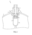
- Figure 2 shows a noise reduction member in the form of a compressible fluid discharge muffler 20 comprising a tubular body 22 having an open first end 15 for receiving a compressed fluid and a restricting second end 17 for discharging the compressed fluid.
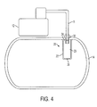
- the compressible fluid discharge muffler 20 is connected to the intake port 18 of the air storage tank 14.
- the intake port 18 receives a fluid, such as air, that is compressed by the compressor 12.
- the muffler 20 serves to reduce the vibration of pressurized fluid, such as air entering the storage tank, and thereby the noise caused by the vibration.
- the tubular body 22 of the compressible fluid discharge muffler 20 has a cavity 23 defined by an inlet 24 at a first end and an outlet 26 at a second end opposing the first end.
- the outlet 26 of the muffler 20 discharges pressurized air into the tank 14.
- the inlet 24 of the tubular body 22 in Figure 2 has a greater diameter than the outlet 26, thereby creating a restricted flow path for air being delivered from the compressor 12 to the interior of the air storage tank 14. As the outlet 26 is smaller than the inlet, the outlet acts as a restricting means downstream of the inlet 24.
- the volume and outlet of the tubular body 22 forming the muffler 20 are sized to reduce the high velocity air flow pulsations from the compressor 12 into the air storage tank 14 that result in reduced tank wall vibration and tank noise.
- the second end of the tubular body 22 can have any shape including, but not limited to, the rounded U-shape shown in the figures.
- the second end of the tubular body can be flat as shown in Figure 4 .
- the muffler outlet 26 can also have sidewalls 27 that are parallel to the direction of fluid flow.
- Figure 2 illustrates a single aperture forming the outlet 26 at the second end of the tubular body, the outlet end of the tubular body 22 can have a plurality of apertures.
- the muffler 20 can be made from any material including, but not limited to, aluminum, brass, and plated steel, or be plastic molded.
- the muffler is illustrated as tubular, the muffler can be any shape, including spherical.
- the muffler 20 can also accommodate a non-return or check valve 30 in the first end thereof.
- the check valve can be in the form of a body having an inlet portion for the entrance of fluid and an outlet portion for the discharge of the fluid.
- the check valve 30 inhibits air from returning to the compressor 12 from the air storage tank 14.
- the check valve includes a seat 29 on the body and a disk 28 that is movable toward the seat to contact the seat and thereby close the valve, and away from the seat to open the valve.
- the disk 28 is biased in a direction toward the seat 29 by a spring 32 to close the valve.
- the check valve 30 inlet portion disposed within the air discharge tube 11 connecting the compressor 12 and the air storage tank 14.
- the check valve 30 can be at least partially inserted into the inlet 24 in the first end of the tubular body 22. An outlet portion of the check valve 30 is disposed within the inlet 24 of the tubular body 22.
- the muffler 20 creates an enclosed air volume around the portion of the check valve 30 that is inserted into the air storage tank 14.
- the muffler 20 can be mounted to the air storage tank 14 through the intake port 18 as follows.
- a weld flange 34 having a threaded inner surface 35 can be secured to the air storage tank 14 by a weld bead 36.
- a check valve 30 having a threaded outer surface can be threaded into the weld flange 34.
- the muffler 20 can be connected to the check valve 30 by press-fitting or crimping a flanged upper end to the surface of the check valve.
- Other connection methods of the muffler to a check valve include brazing and adhering with an epoxy.
- the weld flange 34, 54 can be forged from steel and the weld bead 36, 56 can be made from a steel alloy or any compatible material used to weld a flange to an air storage tank.
- the weld flange 34, 54 and weld bead 36, 56 can be made from any combination of compatible materials including, but not limited to aluminum, copper, brass, plastic and steel.
- the weld flange and weld bead can be joined by any compatible joining process.
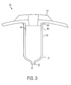
- the muffler 40 can be welded directly to the air storage tank 14.
- the muffler 40 includes a tubular body 42 having an inlet 44 at a first end and an outlet 46 at a second end opposing the first end.
- the inlet 44 has a greater diameter than the outlet 46.
- the muffler 40 is integrally connected to the air storage tank 14.
- the tubular body 42 is welded with weld bead 56 at the intake port 18 on an inner wall of the air storage tank 14.
- the outlet 46 of muffler 40 restricts the flow of air being delivered from the compressor 12 to the air storage tank 14.
- the upper outer surface of the muffler can be a threaded surface that is threaded onto an inner threaded surface of the weld flange.
- the upper inner surface of the muffler can be a threaded surface that is threaded onto an outer threaded surface of the weld flange 34.
- the outlet 46 in the second end of the muffler 40 can have a flared opening 52 that extends beyond the bottom surface of the tubular body of the muffler.
- the flared opening 52 can have any configuration, such as, for example, convex inner sides as shown in Figure 3 .
- the second end of the muffler 40 can be formed by piercing, drilling, or any suitable method for forming an aperture in the bottom of a tube.
- the muffler can be disposed along the path between the outlet of the compressor and the inlet to the air storage tank.
- the muffler 20 can be formed so that the restriction portion is downstream from the inlet of the tubular body 22 and upstream of the pressurized air inlet into the air storage tank 14.
- the muffler 20 can be fully disposed within the air storage tank 14.
- the muffler 520 can be disposed within the head 513 of the compressor 512.
- the muffler 520 has a restricting outlet 526 at the second end of the tubular body 522.
- the restricting outlet 526 is disposed upstream of or within the inlet of the air discharge tube 511.
- the air discharge tube 511 carries the compressed air to the air storage tank 514.
- Figure 6 illustrates that the muffler 620 can be completely disposed within the air discharge tube 611 connecting the compressor 612 and air storage tank 614.
- the muffler 620 is outside of both the air storage tank 614 and the head 613 of the compressor 612 and the restricting outlet 626 is immediately upstream of the check valve 630.
- the check valve 830 is located downstream from the muffler cavity 823 of the muffler 820.
- the check valve has an inlet 832 and channel 834 in line with the fluid flow.
- the inlet 832 and channel 834 that are sized to reduce the speed of the high velocity air entering the air storage tank 814.
- Pressurized air being delivered from the compressor 812 passes through the discharge tube 811 to the muffler 820 enters and is discharged from the muffler/check valve combination, through a restricting outlet 826 in the check valve 830. The pressurized air then enters the air storage tank 814.
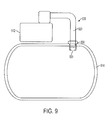
- the muffler 920 serves as the air discharge tube for pressurized air being delivered from the compressor 912 to the air storage tank 914.
- the muffler cavity 923 extends from the compressor to the check valve 930 serving as the restricting member. Pressurized air is discharged from the muffler/check valve combination through the outlet 926 and enters the air storage tank 914.
- More than one muffler of the present invention can be used in series along the path between the compressor and the air storage tank.
- the muffler can also protect the check valve from corrosion caused by condensate in the air storage tank. Tilting of the compressor, for example, during movement from one location to another location, could allow water or other condensate to enter into air compressor.
- the check valve serves to check the flow of fluid from the air storage tank to the compressor. However, if the check valve comes in contact with water or other liquid condensate, over time, the check valve will tend to corrode. In the above-described embodiments shown in Figures 1-4 , the length of the cavity 23 in the tubular body 22 of the muffler 2, restricts the liquid condensate from entering the check valve 30 from the air storage tank 14.
- the mufflers are illustrated as being inserted through a top or upper surface of the air storage tank.
- the mufflers can also be inserted into the air storage tank through a bottom or lower surface of the tank. In such an arrangement, the mufflers can be inserted above the high water or condensate line.
Landscapes
- Engineering & Computer Science (AREA)
- Mechanical Engineering (AREA)
- General Engineering & Computer Science (AREA)
- Compressor (AREA)
- Compressors, Vaccum Pumps And Other Relevant Systems (AREA)
- Pipe Accessories (AREA)
- Exhaust Silencers (AREA)
Abstract
Description
- The present application claims priority under 35 U.S.C. §119 to the
U.S. Provisional Application Ser. No. 61/350,226 filed on June 1, 2010 - The present invention relates in general to the field of air compressors and particularly to an apparatus and method for reducing the noise of compressed air entering into an air storage tank in a compressor assembly.
- A compressor assembly normally provides a source of compressible fluid which is temporarily stored in a pressurized fluid tank. Typically, an electric motor or a combustion engine is connected to a compressor unit to activate the compressor. The compressor unit typically includes a piston assembly, or compressor pump, which compresses the fluid and forces it into the fluid pressure tank for temporary storage.
- Likewise, an air compressor assembly provides a source of pressurized air to an air storage tank. Many portable air compressors include a compressor mounted to an air storage tank. The compressor compresses air which is then stored in the air storage tank. The compressor unit compresses air from the atmosphere. The pressurized air in the air storage tank can be used for operating air powered tools such as nailing tools, socket driving tools, material shaping tools, sanding tools, spray painting tools, inflation chucks, and inflating tires and the like.
- In an air compressor assembly, it is common for water and other liquids to condense from the air inside the air storage tank as a consequence of the pressure and temperature differences inside the tank and outside the tank. Water and other liquids that may accumulate inside the air storage tank may be removed through the installation of a condensate removal device placed near a low point of the air storage tank. However, any tilting of the compressor, for example, during movement from one location to another location, could allow water to enter into the air intake port of the compressor. Check valves are placed in the air intake port of an air storage tank near the top surface to prevent water or liquid condensate from flowing out of the tank toward the compressor. However, check valves can suffer from corrosion due to contact with the condensate.
- One long unresolved problem with such air compressor assemblies is that they tend to generate significant noise when compressed air is discharged from the compressor to the air storage tank. Vibrations and noise make the operation of the compressor less comfortable. Specifically, air storage tanks receiving pressurized air from a compressor generate significant vibrations. Vibrations are generated as bursts of high velocity air create shockwaves that hit the inner walls of the air compressor tank. The shockwaves in turn, generate noise outside of the tank. This noise includes ringing and rattling caused by the bursts of high velocity air as the air passes from the compressor through the connecting tube and hits the inner walls of the storage tank. The noise has been compared to metal ball bearings rattling inside of an empty metal tank.
- It is desirable to provide an apparatus and method that reduces the noise and vibration from the storage tank during the operation of an air compressor.
- This application relates to an apparatus and method for reducing the noise of a compressed fluid, such as air entering a storage tank. The apparatus and method disclosed herein allow users to effectively reduce the noise and vibration of the air storage tank caused by the air entering the tank.
- In an exemplary embodiment of the present invention, an air compressor assembly includes an air compressor and an air storage tank suitable for storing pressurized air and having an intake port in an upper surface of the air storage tank. A noise reduction member is disposed between the compressor and the air storage tank and is capable of reducing noise generated by the delivery of pressurized air from the compressor to the air storage tank. The noise reduction member captures the high velocity bursts of pressurized air and discharges the air at a slower velocity and thereby more continuous flow.
- Advantages include at least the following: less vibration of the tank caused by the pulses of air coming out of the compressor, resulting in less noise. The pulsing of air is caused by the stop-and-go push of air from the compressor. Reducing air storage tank vibration and noise, makes the operation of the compressor more comfortable and a more positive experience for the user. In addition, environmental noise produced by the air tank is reduced.
- Other advantages and features will be apparent from the description, the drawings, and the claims.
- It is to be understood that both the foregoing general description and the following detailed description are exemplary and explanatory only and are not restrictive of the invention as claimed. The accompanying drawings, which are incorporated in and constitute a part of the specification, illustrate an embodiment of the invention and together with the general description, serve to explain the principles of the invention.
- The numerous advantages of the present invention may be better understood by those skilled in the art by reference to the accompanying figures. In the drawings, like reference numerals designate corresponding parts throughout the several views.
-
Figure 1 illustrates a first embodiment of a compressor assembly; -
Figure 2 is a cross-sectional view of a first embodiment of the compressible fluid discharge muffler; -
Figure 3 is a cross-sectional view of a second embodiment of the compressible fluid discharge muffler; -
Figure 4 is a cross-sectional view of the compressible fluid discharge muffler in a first arrangement of an air compressor assembly; -
Figure 5 is a cross-sectional view of the compressible fluid discharge muffler in a second arrangement of an air compressor assembly; -
Figure 6 is a cross-sectional view of the compressible fluid discharge muffler in a third arrangement of an air compressor assembly; -
Figure 7 is a cross-sectional view of the compressible fluid discharge muffler in a fourth arrangement of an air compressor assembly; -
Figure 8 is a cross-sectional view of the compressible fluid discharge muffler in a second embodiment of the present invention; and -
Figure 9 is a cross-sectional view of the compressible fluid discharge muffler in a third embodiment of the present invention. - Reference will now be made in detail to the presently preferred embodiments of the invention, examples of which are illustrated in the accompanying drawings.
- Referring generally to
Figure 1 , anair compressor assembly 10 in accordance with an exemplary embodiment of the present invention is described. As shown inFigure 1 , theair compressor assembly 10 includes acompressor 12 mounted to a compressedair storage tank 14, a motor (not shown) and anair discharge tube 11. Theair storage tank 14 provides a tank or receiver for storing a fluid, such as air, under pressure. - A discharge port (not shown) is provided in the
air storage tank 14 to which a pressure manifold or pipe is fitted allowing compressed air to be drawn from thetank 14 for powering air powered tools such as nailing tools, socket driving tools, material shaping tools, sanding tools, spray painting tools, and tire inflation chucks. - A wide variety of compressor assemblies have storage tanks with walls that are sufficiently flexible to transmit noise. Such compressor assemblies including vertical tank compressors, horizontal tank compressors, twin tank compressors, pancake compressors and the like for pressurizing air from a first pressure to a second higher pressure, may implement the principles of the present invention. For example, in one embodiment, shown in
Figure 1 , the compressedair storage tank 14 of theair compressor assembly 10 may be comprised of a flattened oval or "pancake" style tank. The air storage tank may also take a variety of shapes and positions without departing from the spirit and scope of the present invention. - A pressure switch assembly inside of the compressor is mounted to the
pressure manifold 13 for regulating pressure within theair storage tank 14 by alternately starting and stopping thecompressor 12 to periodically replenish the supply of air in thetank 14. When pressure within thetank 14 reaches a preset low pressure point, or "kick-in pressure," the pressure switch assembly starts thecompressor 12 to re-pressurize thetank 14. The compressed air generated by thecompressor 12 passes through theair discharge tube 11 into theair storage tank 14. As the pressure within thetank 14 reaches a preset high pressure point, or "kick-out pressure," the pressure switch assembly stops thecompressor 12 to prevent overpressurization of thetank 14. In this manner, the pressure of the compressed air in the compressedair storage tank 14 is maintained within a range generally suitable for powering one or more air powered tools. In operation, rotation of the motor activates thecompressor 12 thereby initiating a supply of compressed air to anintake port 18 located on thestorage tank 14. - When the
air compressor 12 is operating to replenish the supply of air in theair storage tank 14, noise and vibration are generated by air entering thetank 14 in bursts due to the piston movement. A noise reduction member of the present invention reduces the noise of pressurized air entering the air tank. -
Figure 2 shows a noise reduction member in the form of a compressiblefluid discharge muffler 20 comprising atubular body 22 having an openfirst end 15 for receiving a compressed fluid and a restrictingsecond end 17 for discharging the compressed fluid. The compressiblefluid discharge muffler 20 is connected to theintake port 18 of theair storage tank 14. Theintake port 18 receives a fluid, such as air, that is compressed by thecompressor 12. Themuffler 20 serves to reduce the vibration of pressurized fluid, such as air entering the storage tank, and thereby the noise caused by the vibration. Thetubular body 22 of the compressiblefluid discharge muffler 20 has acavity 23 defined by aninlet 24 at a first end and anoutlet 26 at a second end opposing the first end. Theoutlet 26 of themuffler 20 discharges pressurized air into thetank 14. - The
inlet 24 of thetubular body 22 inFigure 2 has a greater diameter than theoutlet 26, thereby creating a restricted flow path for air being delivered from thecompressor 12 to the interior of theair storage tank 14. As theoutlet 26 is smaller than the inlet, the outlet acts as a restricting means downstream of theinlet 24. The volume and outlet of thetubular body 22 forming themuffler 20 are sized to reduce the high velocity air flow pulsations from thecompressor 12 into theair storage tank 14 that result in reduced tank wall vibration and tank noise. - The second end of the
tubular body 22 can have any shape including, but not limited to, the rounded U-shape shown in the figures. For example, the second end of the tubular body can be flat as shown inFigure 4 . Themuffler outlet 26 can also have sidewalls 27 that are parallel to the direction of fluid flow. In addition, althoughFigure 2 illustrates a single aperture forming theoutlet 26 at the second end of the tubular body, the outlet end of thetubular body 22 can have a plurality of apertures. - The
muffler 20 can be made from any material including, but not limited to, aluminum, brass, and plated steel, or be plastic molded. In addition, although the muffler is illustrated as tubular, the muffler can be any shape, including spherical. - As illustrated in
Figure 2 , for example, themuffler 20 can also accommodate a non-return orcheck valve 30 in the first end thereof. The check valve can be in the form of a body having an inlet portion for the entrance of fluid and an outlet portion for the discharge of the fluid. Thecheck valve 30 inhibits air from returning to thecompressor 12 from theair storage tank 14. The check valve includes a seat 29 on the body and adisk 28 that is movable toward the seat to contact the seat and thereby close the valve, and away from the seat to open the valve. Thedisk 28 is biased in a direction toward the seat 29 by aspring 32 to close the valve. Thecheck valve 30 inlet portion disposed within theair discharge tube 11 connecting thecompressor 12 and theair storage tank 14. Thecheck valve 30 can be at least partially inserted into theinlet 24 in the first end of thetubular body 22. An outlet portion of thecheck valve 30 is disposed within theinlet 24 of thetubular body 22. Themuffler 20 creates an enclosed air volume around the portion of thecheck valve 30 that is inserted into theair storage tank 14. - Also, as illustrated in
Figure 2 , themuffler 20 can be mounted to theair storage tank 14 through theintake port 18 as follows. Aweld flange 34 having a threadedinner surface 35 can be secured to theair storage tank 14 by aweld bead 36. Acheck valve 30 having a threaded outer surface can be threaded into theweld flange 34. Themuffler 20 can be connected to thecheck valve 30 by press-fitting or crimping a flanged upper end to the surface of the check valve. Other connection methods of the muffler to a check valve include brazing and adhering with an epoxy. - The
weld flange weld bead weld flange weld bead - In a second embodiment of the present invention, shown in
Figure 3 , themuffler 40 can be welded directly to theair storage tank 14. Themuffler 40 includes atubular body 42 having aninlet 44 at a first end and anoutlet 46 at a second end opposing the first end. Theinlet 44 has a greater diameter than theoutlet 46. Themuffler 40 is integrally connected to theair storage tank 14. For example, as shown inFigure 3 , thetubular body 42 is welded withweld bead 56 at theintake port 18 on an inner wall of theair storage tank 14. Theoutlet 46 ofmuffler 40 restricts the flow of air being delivered from thecompressor 12 to theair storage tank 14. - Alternatively, the upper outer surface of the muffler can be a threaded surface that is threaded onto an inner threaded surface of the weld flange. Also, the upper inner surface of the muffler can be a threaded surface that is threaded onto an outer threaded surface of the
weld flange 34. - As shown in
Figure 3 , theoutlet 46 in the second end of themuffler 40 can have a flaredopening 52 that extends beyond the bottom surface of the tubular body of the muffler. The flaredopening 52 can have any configuration, such as, for example, convex inner sides as shown inFigure 3 . The second end of themuffler 40 can be formed by piercing, drilling, or any suitable method for forming an aperture in the bottom of a tube. - The muffler can be disposed along the path between the outlet of the compressor and the inlet to the air storage tank. For example, the
muffler 20 can be formed so that the restriction portion is downstream from the inlet of thetubular body 22 and upstream of the pressurized air inlet into theair storage tank 14. Alternatively, as shown inFigures 2 ,3 and4 , for example, themuffler 20 can be fully disposed within theair storage tank 14. - As a further alternative shown in the schematic of
Figure 5 , themuffler 520 can be disposed within thehead 513 of thecompressor 512. In the arrangement ofFigure 5 , themuffler 520 has a restrictingoutlet 526 at the second end of thetubular body 522. The restrictingoutlet 526 is disposed upstream of or within the inlet of theair discharge tube 511. Theair discharge tube 511 carries the compressed air to theair storage tank 514. - In a further alternative arrangement,
Figure 6 illustrates that themuffler 620 can be completely disposed within theair discharge tube 611 connecting thecompressor 612 andair storage tank 614. Themuffler 620 is outside of both theair storage tank 614 and thehead 613 of thecompressor 612 and the restrictingoutlet 626 is immediately upstream of thecheck valve 630. -
Figure 7 illustrates a second embodiment of the invention, wherein thedischarge tube 711 serves as the restricting outlet. Themuffler 720 is disposed within thehead 713 of thecompressor 712. In this arrangement, theair discharge tube 711 downstream from themuffler cavity 723 has a diameter significantly smaller than the muffler cavity. As such, theair discharge tube 711 slows the high velocity burst of air from the compressor so that the air enters the air storage tank at a slower or continuous flow thereby reducing the vibrations and noise in thetank 714. -
Figures 8 and9 illustrate third and fourth embodiments, respectively, of the present invention wherein a check valve portion of the compressible fluid discharge muffler restricts the high velocity bursts of pressurized air entering the air storage tank. In the embodiments ofFigures 8 and9 , the check valve serves as a restriction member for the muffler. - In
Figure 8 , for example, thecheck valve 830 is located downstream from themuffler cavity 823 of themuffler 820. The check valve has aninlet 832 andchannel 834 in line with the fluid flow. Theinlet 832 andchannel 834 that are sized to reduce the speed of the high velocity air entering theair storage tank 814. Pressurized air being delivered from thecompressor 812 passes through thedischarge tube 811 to themuffler 820 enters and is discharged from the muffler/check valve combination, through a restrictingoutlet 826 in thecheck valve 830. The pressurized air then enters theair storage tank 814. - In the fourth embodiment of
Figure 9 , themuffler 920 serves as the air discharge tube for pressurized air being delivered from thecompressor 912 to theair storage tank 914. Themuffler cavity 923 extends from the compressor to thecheck valve 930 serving as the restricting member. Pressurized air is discharged from the muffler/check valve combination through theoutlet 926 and enters theair storage tank 914. - More than one muffler of the present invention can be used in series along the path between the compressor and the air storage tank.
- The muffler can also protect the check valve from corrosion caused by condensate in the air storage tank. Tilting of the compressor, for example, during movement from one location to another location, could allow water or other condensate to enter into air compressor. The check valve serves to check the flow of fluid from the air storage tank to the compressor. However, if the check valve comes in contact with water or other liquid condensate, over time, the check valve will tend to corrode. In the above-described embodiments shown in
Figures 1-4 , the length of thecavity 23 in thetubular body 22 of the muffler 2, restricts the liquid condensate from entering thecheck valve 30 from theair storage tank 14. - The mufflers are illustrated as being inserted through a top or upper surface of the air storage tank. The mufflers can also be inserted into the air storage tank through a bottom or lower surface of the tank. In such an arrangement, the mufflers can be inserted above the high water or condensate line.
- Although the invention has been described based upon these preferred embodiments, it would be apparent to those skilled in the art that certain modifications, variations, and alternative constructions would be apparent, while remaining within the spirit and scope of the invention.
Claims (14)
- A noise reduction device comprising:a tubular body having an open first end, a second end opposite the first end, and a cavity located between the first end and the second end, the second end being opposite the first end and having at least one opening, the at least one opening having a diameter smaller than the diameter of the opening in the first end;
wherein the at least one opening in the second end is opposite from the opening in the first end. - The noise reduction device according to claim 1, wherein the second end of the tubular body is flat.
- The noise reduction device according to claim 1, wherein the at least one opening in the second end of the tubular body has a diameter that is at least 50% smaller than the diameter of the opening in the first end.
- The noise reduction device according to claim 1, wherein the at least one opening in the second end of the tubular body has parallel sidewalls.
- The noise reduction device according to claim 1, wherein the at least one opening in the second end of the tubular body has flared walls.
- The noise reduction device according to claim 1, wherein the second end of the tubular body has a plurality of openings.
- A compressor assembly comprising:a compressor having a head portion mounted thereto, a discharge port in the head portion and a discharge tube connected to the discharge port in the head portion;a storage tank having an intake port connected to the discharge tube to receive pressurized fluid from the compressor;a check valve arranged between the compressor and the storage tank; anda muffler disposed between the compressor and an inner wall of the storage tank, the muffler comprising a tubular body having an opening in a first end, a second end opposite the first end, and cavity located between the first end and the second end, the second end having at least one opening with a diameter smaller than the diameter of the opening in the first end.
- The noise reduction assembly according to claim 7, wherein the muffler is disposed within the head portion of the compressor.
- The noise reduction assembly according to claim 7, wherein the muffler is disposed within the discharge tube.
- The noise reduction assembly according to claim 7, wherein the muffler is disposed between the compressor head and the check valve.
- The noise reduction assembly according to claim 10, wherein the muffler is disposed between the discharge tube and the check valve.
- The noise reduction assembly according to claim 7, wherein the intake port of the storage tank is outside of a condensate line.
- The noise reduction assembly according to claim 7, wherein the muffler is disposed within the storage tank and the opening in a first end circumscribes and is crimped to the fluid outlet portion of the check valve.
- A method of making a noise reduction assembly in an air compressor, the method comprising:providing an air compressor operatively connectable to an air storage tank by a discharge tube, the discharge tube having a receiving end for receiving compressed air from the compressor and a discharge end for discharging the compressed air into an intake port in the air storage tank; andwelding a noise reduction device to the intake port in the air storage tank, the noise reduction device including:a tubular body having an open first end, a second end opposite the first end, and a cavity located between the first end and the second end, the second end being opposite the first end and having at least one opening, the at least one opening having a diameter smaller than the diameter of the opening in the first end;wherein the at least one opening in the second end is adjacent to a point directly opposite from the opening in the first end.
Applications Claiming Priority (2)
| Application Number | Priority Date | Filing Date | Title |
|---|---|---|---|
| US35022610P | 2010-06-01 | 2010-06-01 | |
| US13/117,560 US20110290354A1 (en) | 2010-06-01 | 2011-05-27 | Compressible Fluid Discharge Muffler |
Publications (2)
| Publication Number | Publication Date |
|---|---|
| EP2392823A2 true EP2392823A2 (en) | 2011-12-07 |
| EP2392823A3 EP2392823A3 (en) | 2017-03-08 |
Family
ID=45066024
Family Applications (1)
| Application Number | Title | Priority Date | Filing Date |
|---|---|---|---|
| EP11168343.9A Withdrawn EP2392823A3 (en) | 2010-06-01 | 2011-06-01 | Compressible Fluid Discharge Muffler |
Country Status (4)
| Country | Link |
|---|---|
| US (1) | US20110290354A1 (en) |
| EP (1) | EP2392823A3 (en) |
| CN (1) | CN102312819B (en) |
| CA (1) | CA2741264A1 (en) |
Cited By (1)
| Publication number | Priority date | Publication date | Assignee | Title |
|---|---|---|---|---|
| US11204022B2 (en) | 2018-08-14 | 2021-12-21 | Milwaukee Electric Tool Corporation | Air compressor |
Families Citing this family (4)
| Publication number | Priority date | Publication date | Assignee | Title |
|---|---|---|---|---|
| KR101927381B1 (en) * | 2017-10-12 | 2018-12-07 | 뉴모텍(주) | Machine Tool System having Compact Air Compressor |
| IT202100018482A1 (en) * | 2021-07-13 | 2023-01-13 | Fna S P A | SILENCER AND AIR TANK FOR AN AIR COMPRESSOR ASSEMBLY, ESPECIALLY A PISTON AIR COMPRESSOR |
| JP7628915B2 (en) * | 2021-08-05 | 2025-02-12 | 株式会社マキタ | Air Compressor |
| CN113883038B (en) * | 2021-10-29 | 2025-03-28 | 珠海格力电器股份有限公司 | Gas buffers, compressors and air conditioners |
Family Cites Families (12)
| Publication number | Priority date | Publication date | Assignee | Title |
|---|---|---|---|---|
| US1909511A (en) * | 1929-11-01 | 1933-05-16 | Gen Motors Res Corp | Muffler |
| US2136098A (en) * | 1937-07-28 | 1938-11-08 | Kellogg Compressor And Mfg Cor | Air compressing apparatus |
| US2962110A (en) * | 1957-08-09 | 1960-11-29 | Gen Motors Corp | Surge muffler for air storage tank |
| US2964120A (en) * | 1958-12-19 | 1960-12-13 | Gen Motors Corp | High pressure storage tank inlet fiting and muffler assembly |
| US4557257A (en) * | 1983-07-21 | 1985-12-10 | Fernandez Jose M | Pneumatic walking brace and operating system |
| CN85201134U (en) * | 1985-04-30 | 1986-04-09 | 西安交通大学 | Air compressor exhaust unit with noise silencer |
| DE69009240T2 (en) * | 1989-03-10 | 1994-09-08 | Neriki Kk | Valve arrangement with shut-off valve for gas containers. |
| US5133647A (en) * | 1989-07-07 | 1992-07-28 | Ultra-Precision Manufacturing, Ltd. | Pulse damper |
| AU691270B2 (en) * | 1994-06-24 | 1998-05-14 | Kabushiki Kaisha Neriki | Valve assembly for gas cylinder |
| US6102679A (en) * | 1998-03-12 | 2000-08-15 | Brown; Gerald E. | Air compressor |
| KR100408245B1 (en) * | 2001-11-05 | 2003-12-01 | 주식회사 엘지이아이 | Structure for reducing noise in compressor |
| CN2667195Y (en) * | 2003-07-16 | 2004-12-29 | 王健斌 | Air compressor air storing cylinder one-way valve sound silencer |
-
2011
- 2011-05-27 US US13/117,560 patent/US20110290354A1/en not_active Abandoned
- 2011-05-30 CA CA 2741264 patent/CA2741264A1/en not_active Abandoned
- 2011-06-01 CN CN201110226308.4A patent/CN102312819B/en not_active Expired - Fee Related
- 2011-06-01 EP EP11168343.9A patent/EP2392823A3/en not_active Withdrawn
Cited By (2)
| Publication number | Priority date | Publication date | Assignee | Title |
|---|---|---|---|---|
| US11204022B2 (en) | 2018-08-14 | 2021-12-21 | Milwaukee Electric Tool Corporation | Air compressor |
| US12060872B2 (en) | 2018-08-14 | 2024-08-13 | Milwaukee Electric Tool Corporation | Air compressor |
Also Published As
| Publication number | Publication date |
|---|---|
| EP2392823A3 (en) | 2017-03-08 |
| US20110290354A1 (en) | 2011-12-01 |
| CN102312819B (en) | 2017-03-01 |
| CN102312819A (en) | 2012-01-11 |
| CA2741264A1 (en) | 2011-12-01 |
Similar Documents
| Publication | Publication Date | Title |
|---|---|---|
| US20110290354A1 (en) | Compressible Fluid Discharge Muffler | |
| CN100424348C (en) | Head pressure relief assembly and compressor using head pressure relief assembly | |
| US7117856B2 (en) | Fuel delivery systems | |
| CN103052515B (en) | Tubeless tire seating device | |
| US20130011283A1 (en) | Air Compressor | |
| US6692238B2 (en) | Muffler of compressor | |
| JP4109122B2 (en) | Intake gas guidance system for reciprocating compressors | |
| EP1733902A3 (en) | Tire Pump | |
| MXPA04004001A (en) | Suction muffler for a reciprocating hermetic compressor. | |
| KR20120088775A (en) | Puncture repair kit | |
| US6102679A (en) | Air compressor | |
| EP4080055B1 (en) | Air stop sheet of piston of cylinder | |
| JPH11502280A (en) | High pressure gas compressor | |
| US7563077B2 (en) | Quiet fluid pump | |
| JP2015036514A (en) | Compressor | |
| JP4560828B2 (en) | Air compressor intake noise reduction structure | |
| CN100406713C (en) | Oil returning valve structure of engine | |
| CN216877652U (en) | Fire suppression device | |
| CN101871444A (en) | Muffler | |
| CN201794743U (en) | Silencer | |
| JP2907243B2 (en) | air compressor | |
| JP3971207B2 (en) | Compressor | |
| US20140239097A1 (en) | Venturi fluid pump with outlet flow controller | |
| CN101684786A (en) | Silencer of compressor | |
| JP4925782B2 (en) | Flow control valve |
Legal Events
| Date | Code | Title | Description |
|---|---|---|---|
| AK | Designated contracting states |
Kind code of ref document: A2 Designated state(s): AL AT BE BG CH CY CZ DE DK EE ES FI FR GB GR HR HU IE IS IT LI LT LU LV MC MK MT NL NO PL PT RO RS SE SI SK SM TR |
|
| AX | Request for extension of the european patent |
Extension state: BA ME |
|
| PUAI | Public reference made under article 153(3) epc to a published international application that has entered the european phase |
Free format text: ORIGINAL CODE: 0009012 |
|
| PUAL | Search report despatched |
Free format text: ORIGINAL CODE: 0009013 |
|
| AK | Designated contracting states |
Kind code of ref document: A3 Designated state(s): AL AT BE BG CH CY CZ DE DK EE ES FI FR GB GR HR HU IE IS IT LI LT LU LV MC MK MT NL NO PL PT RO RS SE SI SK SM TR |
|
| AX | Request for extension of the european patent |
Extension state: BA ME |
|
| RIC1 | Information provided on ipc code assigned before grant |
Ipc: F04B 41/02 20060101ALI20170201BHEP Ipc: F04B 35/06 20060101AFI20170201BHEP Ipc: F04B 39/00 20060101ALI20170201BHEP |
|
| STAA | Information on the status of an ep patent application or granted ep patent |
Free format text: STATUS: REQUEST FOR EXAMINATION WAS MADE |
|
| 17P | Request for examination filed |
Effective date: 20170523 |
|
| RBV | Designated contracting states (corrected) |
Designated state(s): AL AT BE BG CH CY CZ DE DK EE ES FI FR GB GR HR HU IE IS IT LI LT LU LV MC MK MT NL NO PL PT RO RS SE SI SK SM TR |
|
| STAA | Information on the status of an ep patent application or granted ep patent |
Free format text: STATUS: THE APPLICATION IS DEEMED TO BE WITHDRAWN |
|
| 18D | Application deemed to be withdrawn |
Effective date: 20170909 |