EP2392487A2 - Apparatus and method for controlling a relay of a hybrid electric vehicle - Google Patents
Apparatus and method for controlling a relay of a hybrid electric vehicle Download PDFInfo
- Publication number
- EP2392487A2 EP2392487A2 EP10748957A EP10748957A EP2392487A2 EP 2392487 A2 EP2392487 A2 EP 2392487A2 EP 10748957 A EP10748957 A EP 10748957A EP 10748957 A EP10748957 A EP 10748957A EP 2392487 A2 EP2392487 A2 EP 2392487A2
- Authority
- EP
- European Patent Office
- Prior art keywords
- relay
- residual current
- electric drive
- battery pack
- turn
- Prior art date
- Legal status (The legal status is an assumption and is not a legal conclusion. Google has not performed a legal analysis and makes no representation as to the accuracy of the status listed.)
- Granted
Links
Images


Classifications
-
- B—PERFORMING OPERATIONS; TRANSPORTING
- B60—VEHICLES IN GENERAL
- B60L—PROPULSION OF ELECTRICALLY-PROPELLED VEHICLES; SUPPLYING ELECTRIC POWER FOR AUXILIARY EQUIPMENT OF ELECTRICALLY-PROPELLED VEHICLES; ELECTRODYNAMIC BRAKE SYSTEMS FOR VEHICLES IN GENERAL; MAGNETIC SUSPENSION OR LEVITATION FOR VEHICLES; MONITORING OPERATING VARIABLES OF ELECTRICALLY-PROPELLED VEHICLES; ELECTRIC SAFETY DEVICES FOR ELECTRICALLY-PROPELLED VEHICLES
- B60L3/00—Electric devices on electrically-propelled vehicles for safety purposes; Monitoring operating variables, e.g. speed, deceleration or energy consumption
- B60L3/0023—Detecting, eliminating, remedying or compensating for drive train abnormalities, e.g. failures within the drive train
- B60L3/0046—Detecting, eliminating, remedying or compensating for drive train abnormalities, e.g. failures within the drive train relating to electric energy storage systems, e.g. batteries or capacitors
-
- B—PERFORMING OPERATIONS; TRANSPORTING
- B60—VEHICLES IN GENERAL
- B60L—PROPULSION OF ELECTRICALLY-PROPELLED VEHICLES; SUPPLYING ELECTRIC POWER FOR AUXILIARY EQUIPMENT OF ELECTRICALLY-PROPELLED VEHICLES; ELECTRODYNAMIC BRAKE SYSTEMS FOR VEHICLES IN GENERAL; MAGNETIC SUSPENSION OR LEVITATION FOR VEHICLES; MONITORING OPERATING VARIABLES OF ELECTRICALLY-PROPELLED VEHICLES; ELECTRIC SAFETY DEVICES FOR ELECTRICALLY-PROPELLED VEHICLES
- B60L50/00—Electric propulsion with power supplied within the vehicle
- B60L50/50—Electric propulsion with power supplied within the vehicle using propulsion power supplied by batteries or fuel cells
-
- B—PERFORMING OPERATIONS; TRANSPORTING
- B60—VEHICLES IN GENERAL
- B60K—ARRANGEMENT OR MOUNTING OF PROPULSION UNITS OR OF TRANSMISSIONS IN VEHICLES; ARRANGEMENT OR MOUNTING OF PLURAL DIVERSE PRIME-MOVERS IN VEHICLES; AUXILIARY DRIVES FOR VEHICLES; INSTRUMENTATION OR DASHBOARDS FOR VEHICLES; ARRANGEMENTS IN CONNECTION WITH COOLING, AIR INTAKE, GAS EXHAUST OR FUEL SUPPLY OF PROPULSION UNITS IN VEHICLES
- B60K6/00—Arrangement or mounting of plural diverse prime-movers for mutual or common propulsion, e.g. hybrid propulsion systems comprising electric motors and internal combustion engines
- B60K6/20—Arrangement or mounting of plural diverse prime-movers for mutual or common propulsion, e.g. hybrid propulsion systems comprising electric motors and internal combustion engines the prime-movers consisting of electric motors and internal combustion engines, e.g. HEVs
- B60K6/22—Arrangement or mounting of plural diverse prime-movers for mutual or common propulsion, e.g. hybrid propulsion systems comprising electric motors and internal combustion engines the prime-movers consisting of electric motors and internal combustion engines, e.g. HEVs characterised by apparatus, components or means specially adapted for HEVs
- B60K6/28—Arrangement or mounting of plural diverse prime-movers for mutual or common propulsion, e.g. hybrid propulsion systems comprising electric motors and internal combustion engines the prime-movers consisting of electric motors and internal combustion engines, e.g. HEVs characterised by apparatus, components or means specially adapted for HEVs characterised by the electric energy storing means, e.g. batteries or capacitors
-
- B—PERFORMING OPERATIONS; TRANSPORTING
- B60—VEHICLES IN GENERAL
- B60L—PROPULSION OF ELECTRICALLY-PROPELLED VEHICLES; SUPPLYING ELECTRIC POWER FOR AUXILIARY EQUIPMENT OF ELECTRICALLY-PROPELLED VEHICLES; ELECTRODYNAMIC BRAKE SYSTEMS FOR VEHICLES IN GENERAL; MAGNETIC SUSPENSION OR LEVITATION FOR VEHICLES; MONITORING OPERATING VARIABLES OF ELECTRICALLY-PROPELLED VEHICLES; ELECTRIC SAFETY DEVICES FOR ELECTRICALLY-PROPELLED VEHICLES
- B60L3/00—Electric devices on electrically-propelled vehicles for safety purposes; Monitoring operating variables, e.g. speed, deceleration or energy consumption
- B60L3/0023—Detecting, eliminating, remedying or compensating for drive train abnormalities, e.g. failures within the drive train
- B60L3/0069—Detecting, eliminating, remedying or compensating for drive train abnormalities, e.g. failures within the drive train relating to the isolation, e.g. ground fault or leak current
-
- B—PERFORMING OPERATIONS; TRANSPORTING
- B60—VEHICLES IN GENERAL
- B60L—PROPULSION OF ELECTRICALLY-PROPELLED VEHICLES; SUPPLYING ELECTRIC POWER FOR AUXILIARY EQUIPMENT OF ELECTRICALLY-PROPELLED VEHICLES; ELECTRODYNAMIC BRAKE SYSTEMS FOR VEHICLES IN GENERAL; MAGNETIC SUSPENSION OR LEVITATION FOR VEHICLES; MONITORING OPERATING VARIABLES OF ELECTRICALLY-PROPELLED VEHICLES; ELECTRIC SAFETY DEVICES FOR ELECTRICALLY-PROPELLED VEHICLES
- B60L3/00—Electric devices on electrically-propelled vehicles for safety purposes; Monitoring operating variables, e.g. speed, deceleration or energy consumption
- B60L3/04—Cutting off the power supply under fault conditions
-
- B—PERFORMING OPERATIONS; TRANSPORTING
- B60—VEHICLES IN GENERAL
- B60L—PROPULSION OF ELECTRICALLY-PROPELLED VEHICLES; SUPPLYING ELECTRIC POWER FOR AUXILIARY EQUIPMENT OF ELECTRICALLY-PROPELLED VEHICLES; ELECTRODYNAMIC BRAKE SYSTEMS FOR VEHICLES IN GENERAL; MAGNETIC SUSPENSION OR LEVITATION FOR VEHICLES; MONITORING OPERATING VARIABLES OF ELECTRICALLY-PROPELLED VEHICLES; ELECTRIC SAFETY DEVICES FOR ELECTRICALLY-PROPELLED VEHICLES
- B60L3/00—Electric devices on electrically-propelled vehicles for safety purposes; Monitoring operating variables, e.g. speed, deceleration or energy consumption
- B60L3/12—Recording operating variables ; Monitoring of operating variables
-
- B—PERFORMING OPERATIONS; TRANSPORTING
- B60—VEHICLES IN GENERAL
- B60L—PROPULSION OF ELECTRICALLY-PROPELLED VEHICLES; SUPPLYING ELECTRIC POWER FOR AUXILIARY EQUIPMENT OF ELECTRICALLY-PROPELLED VEHICLES; ELECTRODYNAMIC BRAKE SYSTEMS FOR VEHICLES IN GENERAL; MAGNETIC SUSPENSION OR LEVITATION FOR VEHICLES; MONITORING OPERATING VARIABLES OF ELECTRICALLY-PROPELLED VEHICLES; ELECTRIC SAFETY DEVICES FOR ELECTRICALLY-PROPELLED VEHICLES
- B60L50/00—Electric propulsion with power supplied within the vehicle
- B60L50/50—Electric propulsion with power supplied within the vehicle using propulsion power supplied by batteries or fuel cells
- B60L50/52—Electric propulsion with power supplied within the vehicle using propulsion power supplied by batteries or fuel cells characterised by DC-motors
-
- B—PERFORMING OPERATIONS; TRANSPORTING
- B60—VEHICLES IN GENERAL
- B60W—CONJOINT CONTROL OF VEHICLE SUB-UNITS OF DIFFERENT TYPE OR DIFFERENT FUNCTION; CONTROL SYSTEMS SPECIALLY ADAPTED FOR HYBRID VEHICLES; ROAD VEHICLE DRIVE CONTROL SYSTEMS FOR PURPOSES NOT RELATED TO THE CONTROL OF A PARTICULAR SUB-UNIT
- B60W20/00—Control systems specially adapted for hybrid vehicles
-
- B—PERFORMING OPERATIONS; TRANSPORTING
- B60—VEHICLES IN GENERAL
- B60W—CONJOINT CONTROL OF VEHICLE SUB-UNITS OF DIFFERENT TYPE OR DIFFERENT FUNCTION; CONTROL SYSTEMS SPECIALLY ADAPTED FOR HYBRID VEHICLES; ROAD VEHICLE DRIVE CONTROL SYSTEMS FOR PURPOSES NOT RELATED TO THE CONTROL OF A PARTICULAR SUB-UNIT
- B60W30/00—Purposes of road vehicle drive control systems not related to the control of a particular sub-unit, e.g. of systems using conjoint control of vehicle sub-units
-
- H—ELECTRICITY
- H01—ELECTRIC ELEMENTS
- H01H—ELECTRIC SWITCHES; RELAYS; SELECTORS; EMERGENCY PROTECTIVE DEVICES
- H01H47/00—Circuit arrangements not adapted to a particular application of the relay and designed to obtain desired operating characteristics or to provide energising current
- H01H47/002—Monitoring or fail-safe circuits
-
- H—ELECTRICITY
- H01—ELECTRIC ELEMENTS
- H01H—ELECTRIC SWITCHES; RELAYS; SELECTORS; EMERGENCY PROTECTIVE DEVICES
- H01H9/00—Details of switching devices, not covered by groups H01H1/00 - H01H7/00
- H01H9/54—Circuit arrangements not adapted to a particular application of the switching device and for which no provision exists elsewhere
-
- B—PERFORMING OPERATIONS; TRANSPORTING
- B60—VEHICLES IN GENERAL
- B60L—PROPULSION OF ELECTRICALLY-PROPELLED VEHICLES; SUPPLYING ELECTRIC POWER FOR AUXILIARY EQUIPMENT OF ELECTRICALLY-PROPELLED VEHICLES; ELECTRODYNAMIC BRAKE SYSTEMS FOR VEHICLES IN GENERAL; MAGNETIC SUSPENSION OR LEVITATION FOR VEHICLES; MONITORING OPERATING VARIABLES OF ELECTRICALLY-PROPELLED VEHICLES; ELECTRIC SAFETY DEVICES FOR ELECTRICALLY-PROPELLED VEHICLES
- B60L2240/00—Control parameters of input or output; Target parameters
- B60L2240/40—Drive Train control parameters
- B60L2240/54—Drive Train control parameters related to batteries
- B60L2240/549—Current
-
- B—PERFORMING OPERATIONS; TRANSPORTING
- B60—VEHICLES IN GENERAL
- B60W—CONJOINT CONTROL OF VEHICLE SUB-UNITS OF DIFFERENT TYPE OR DIFFERENT FUNCTION; CONTROL SYSTEMS SPECIALLY ADAPTED FOR HYBRID VEHICLES; ROAD VEHICLE DRIVE CONTROL SYSTEMS FOR PURPOSES NOT RELATED TO THE CONTROL OF A PARTICULAR SUB-UNIT
- B60W2510/00—Input parameters relating to a particular sub-units
- B60W2510/24—Energy storage means
- B60W2510/242—Energy storage means for electrical energy
- B60W2510/244—Charge state
-
- B—PERFORMING OPERATIONS; TRANSPORTING
- B60—VEHICLES IN GENERAL
- B60W—CONJOINT CONTROL OF VEHICLE SUB-UNITS OF DIFFERENT TYPE OR DIFFERENT FUNCTION; CONTROL SYSTEMS SPECIALLY ADAPTED FOR HYBRID VEHICLES; ROAD VEHICLE DRIVE CONTROL SYSTEMS FOR PURPOSES NOT RELATED TO THE CONTROL OF A PARTICULAR SUB-UNIT
- B60W2556/00—Input parameters relating to data
- B60W2556/10—Historical data
-
- B—PERFORMING OPERATIONS; TRANSPORTING
- B60—VEHICLES IN GENERAL
- B60Y—INDEXING SCHEME RELATING TO ASPECTS CROSS-CUTTING VEHICLE TECHNOLOGY
- B60Y2400/00—Special features of vehicle units
- B60Y2400/11—Electric energy storages
- B60Y2400/114—Super-capacities
-
- Y—GENERAL TAGGING OF NEW TECHNOLOGICAL DEVELOPMENTS; GENERAL TAGGING OF CROSS-SECTIONAL TECHNOLOGIES SPANNING OVER SEVERAL SECTIONS OF THE IPC; TECHNICAL SUBJECTS COVERED BY FORMER USPC CROSS-REFERENCE ART COLLECTIONS [XRACs] AND DIGESTS
- Y02—TECHNOLOGIES OR APPLICATIONS FOR MITIGATION OR ADAPTATION AGAINST CLIMATE CHANGE
- Y02T—CLIMATE CHANGE MITIGATION TECHNOLOGIES RELATED TO TRANSPORTATION
- Y02T10/00—Road transport of goods or passengers
- Y02T10/60—Other road transportation technologies with climate change mitigation effect
- Y02T10/62—Hybrid vehicles
-
- Y—GENERAL TAGGING OF NEW TECHNOLOGICAL DEVELOPMENTS; GENERAL TAGGING OF CROSS-SECTIONAL TECHNOLOGIES SPANNING OVER SEVERAL SECTIONS OF THE IPC; TECHNICAL SUBJECTS COVERED BY FORMER USPC CROSS-REFERENCE ART COLLECTIONS [XRACs] AND DIGESTS
- Y02—TECHNOLOGIES OR APPLICATIONS FOR MITIGATION OR ADAPTATION AGAINST CLIMATE CHANGE
- Y02T—CLIMATE CHANGE MITIGATION TECHNOLOGIES RELATED TO TRANSPORTATION
- Y02T10/00—Road transport of goods or passengers
- Y02T10/60—Other road transportation technologies with climate change mitigation effect
- Y02T10/70—Energy storage systems for electromobility, e.g. batteries
Definitions
- the present invention relates to an apparatus and a method for controlling a relay in electric drive vehicles, and in particular, to an apparatus and a method for controlling a relay of electric drive vehicles in a situation requiring turn-off of the relay.
- HEVs Hybrid Electrical Vehicles
- EVs Electric Vehicles
- HEVs can run by a motor driven by an electrical energy supplied from a battery pack as well as by an engine consuming fossil fuel. HEVs are controlled to maximum fuel efficiency conforming to driving conditions on the basis of these two types of power sources.
- a driving motor of HEVs is converted from a power mode to a generation mode under the control of HCU (Hybrid Control Unit). Then, the battery pack is charged with an electrical energy produced from a generator (or a driving motor) under the control of BMS (Battery Management System) connected with the HCU.
- HCU Hybrid Control Unit
- BMS Battery Management System
- a driving current is applied from the battery pack to an electric drive unit such as a driving motor, to drive the vehicle or operate the electric drive unit.
- a high-voltage relay In a high-voltage battery system used in large electric loads such as HEVs or the like, a high-voltage relay is turned on only when a battery is used, due to the risk of electric shock. That is to say, when the use of the battery is terminated, or when an emergency occurs such as malfunction of BMS, the relay is turned off to prevent electric shock.
- the present invention is designed to solve the problems, and therefore, it is an object of the present invention to provide a relay control apparatus and method for preventing a high-voltage relay of electric drive vehicles from being damaged at the time of turning off the relay.
- a relay control apparatus controls turn-off of a relay operative to connect an electric drive unit with a battery pack for supplying electrical power to the electric drive unit, and the apparatus comprises a current sensor for measuring and outputting a residual current flowing between the battery pack and the electric drive unit; and a controller for, in a situation requiring turn-off of the relay, receiving the measured residual current value, comparing the measured residual current value with a reference value for the residual current, and controlling to maintain the ON-state of the relay or to turn off the relay on the basis of the comparison results.
- the controller turns off the relay, and if the measured residual current value is larger than the reference value, the controller maintains the ON-state of the relay.
- the controller forcibly turns off the relay.
- the relay control apparatus further comprises a memory for storing the reference value for the residual current.
- a battery control system comprises the relay control apparatus.
- a battery pack according to the present invention comprises the relay control apparatus.
- a relay control method controls turn-off of a relay operative to connect an electric drive unit with a battery pack for supplying electrical power to the electric drive unit, and the method comprises the steps of sensing a situation requiring turn-off of the relay; measuring a residual current flowing between the battery pack and the electric drive unit; comparing the measured residual current value with a reference value for the residual current; and controlling to maintain the ON-state of the relay or to turn off the relay on the basis of the comparison results.
- the relay ON-OFF control step if the measured residual current value is smaller than the reference value, the relay is turned off, and if the measured residual current value is larger than the reference value, the ON-state of the relay is maintained.
- the relay ON-OFF control step if an ON-state maintenance time of the relay is longer than a maximum waiting time, the relay is forcibly turned off.
- the comparing step and the control step are performed by a battery control system.
- a usage termination signal of the battery pack is sensed.
- the relay in case that a residual current exists between a high-voltage battery and a motor at the time of turning off a relay of electric drive vehicles, turning off the relay is not immediately carried out, but once the residual current reaches a predetermined level or lower, the relay is controlled to be turned off, so that it can reduce or eliminate the likelihood that the relay may be damaged due to over-current such as a surge current. Thereby, it can prevent accidents that may be resulted from damage of the relay and reduce the economical burden imposed due to replacement of the relay.
- FIG. 1 is a schematic block diagram illustrating a power supply system of electric drive vehicles, with a relay control apparatus according to a preferred embodiment of the present invention.
- the relay control apparatus is connected to a relay 400 disposed on a transmission line of a power supply system which includes a high-voltage battery pack 100, an electric drive unit 200 and a capacitor 300.
- the relay control apparatus comprises a current sensor 500, a memory 600 and a controller 700.
- the high-voltage battery pack 100 corresponds to a power source that is a supply of electrical power to electric drive vehicles such as HEVs, EVs or the like.
- the electric drive unit 200 is an electronic unit of vehicles that is operated by electrical power supplied from the high-voltage battery pack 100.
- the electric drive unit 200 may be various electric loads in vehicles running on electrical power supplied from the battery pack 100, or generators which charge the battery pack 100.
- the electric drive unit 200 is a driving motor or an alternator.
- the electric drive unit 200 may be various kinds of electric drive equipments in vehicles such as an air conditioner, a head lamp and so on.
- the capacitor 300 is connected with the electric drive unit 200 in parallel, and is generally called a smoothing capacitor or a link capacitor.
- the capacitor 300 rectifies electrical power, and when the battery pack 100 supplies electrical power to the electric drive unit 200, the capacitor 300 limits an abrupt increase in voltage or current.
- the capacitor 300 executing these functions may be selected depending on specification, capacity, usage type or the like, of the battery pack 100 or the electric drive unit 200.
- the relay control apparatus controls the relay 400 in a situation requiring turn-off of the relay.
- a situation requiring turn-off of a relay is a situation where an electric current flowing between the battery pack 100 and the electric drive unit 200 should be shut off, for example, where the usage of the battery pack 100 is terminated, where malfunction of another control device occurs, where a durability test is carried out, where an ignition-off signal of vehicles is sensed or a noisy signal of an ignition key is sensed, and so on.
- the current sensor 500 measures a residual current flowing between the battery pack 100 and the electric drive unit 200 in a situation requiring turn-off of the relay 400.
- FIG. 1 shows that the current sensor 500 is installed between the battery pack 100 and the electric drive unit 200, it is just an exemplary embodiment and the present invention is not limited in this regard. That is, the current sensor 500 may be installed anywhere if a residual current flowing between the battery pack 100 and the electric drive unit 200 can be measured.
- the memory 600 stores a reference value for a residual current flowing between the battery pack 100 and the electric drive unit 200.
- a reference value is a maximum level of a residual current within a range such that the relay 400 is hardly damaged even though it is turned off, or the damage is negligible, if any. It is obvious to an ordinary person skilled in the art that the reference value may vary depending on specification, capacity, usage type or the like, of the battery pack 100 or the electric drive unit 200.
- the memory 600 can store various information including an operating program of the controller 700 therein.
- the memory 600 may be physically separated from the controller 700, but this is just an exemplary embodiment, and the memory 600 may be physically integrated with the controller 700 and be incorporated in the controller 700.
- the controller 700 receives a situation requiring turn-off of the relay 400 from another control device in electric drive vehicles.
- another control device may be BMS, HCU or the like, however the present invention is not limited in this regard, and includes all kinds of devices capable of transmitting a situation requiring turn-off of a relay.
- the controller 700 receives a situation requiring turn-off of the relay 400 from another control device, the controller 700 receives a residual current value measured by the current sensor 500, compares the measured value with a reference value stored in the memory 600, and determines whether or not to turn off the relay 400 on the basis of the comparison results.
- the controller 700 turns off the relay 400. This is because if the measured value is smaller the reference value, it is determined that a residual current does not exist, or if any, the residual current is not enough to damage the relay 400. On the contrary, when the measured residual current value is larger than the reference value, the controller 700 does not immediately turn off the relay 400 but maintains the ON-state of the relay 400. In this case, if the controller 700 immediately turns off the relay 400, the relay 400 may be damaged due to a surge current.
- the controller 700 when the measured residual current value is larger than the reference value stored in the memory 600, the controller 700 forcibly turns off the relay 400 after a predetermined time (maximum waiting time) passes since the controller 700 sensed a situation requiring turn-off of the relay 400. That is, when the measured residual current value is larger than the reference value, the controller 700 maintains the ON-state of the relay 400 temporarily, but after a predetermined time (maximum waiting time) passes, forcibly turns off the relay 400. This is because even though the measured residual current value is more than a predetermined value, if the relay 400 is left in the ON-state all the way, severe accidents such as electric shock may take place.
- the predetermined time may vary depending on specification, capacity, usage type or the like, of the battery pack 100 or the electric drive unit 200, and be pre-stored in the memory 600.
- a battery control system may comprise the above-mentioned relay control apparatus.
- the battery control system generally controls a charging/discharging operation of the battery pack 100, and may be a battery management system (BMS).
- BMS battery management system
- the controller 700, the memory 600 and the current sensor 500 may be included in the battery control system.
- the relay control apparatus may be separate from the battery control system. And, the relay control apparatus may be separately provided outside of the battery pack 100.
- the battery pack 100 may comprise the above-mentioned relay control apparatus.
- the battery pack 100 may further comprise a battery cell assembly including at least one battery cell, and a housing for receiving the battery cell assembly and the relay control apparatus therein.
- FIG. 2 is a flowchart of a relay control method by the relay control apparatus according to an embodiment of the present invention.
- the controller 700 senses a situation requiring turn-off of the relay 400 (S110)
- the controller 700 controls the current sensor 500 to measure a residual current flowing between the battery pack 100 and the electric drive unit 200 (S120).
- the step S110 includes a step of sensing a usage termination signal of the battery pack 100.
- the controller 700 compares the measured residual current value with a reference value stored in the memory 600 (S130). Then, the controller 700 determines whether or not to turn off the relay 400, on the basis of the comparison results (S140).
- the controller 700 determines if a predetermined time has passed since the situation requiring turn-off of the relay 400 was sensed, and in case that the predetermined time has passed, the controller 700 turns off the relay 400.
- the steps S130 and S140 may be performed by a battery control system.
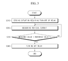
- FIG. 3 is a flowchart of a method for controlling turn-off of a relay in electric drive vehicles according to an embodiment of the present invention.
- the controller 700 controls the current sensor 500 to measure a residual current flowing between the battery pack 100 and the electric drive unit 200 (S220).
- the controller 700 compares the measured residual current value with a reference value stored in the memory 600 (S230). If the measured value is smaller than the reference value, the controller 700 normally turns off the relay 400 (S240). If the measured value is larger than the reference value, the controller 700 does not turn off the relay 400, but maintains the ON-state of the relay 400, and in this state, the controller 700 controls the current sensor 500 to measure a residual current flowing between the battery pack 100 and the electric drive unit 200 again (S220). As long as the measured value is larger than the reference value, the steps S220 and S230 are periodically repeated. That is, if the measured value is larger than the reference value, the ON-state of the relay 400 is maintained.
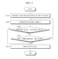
- FIG. 4 is a flowchart of a method for controlling turn-off of a relay in electric drive vehicles according to another embodiment of the present invention.
- the controller 700 senses a situation requiring turn-off of the relay 400 (S310)
- the controller 700 controls the current sensor 500 to measure a residual current flowing between the battery pack 100 and the electric drive unit 200 (S320).
- the controller 700 compares the measured residual current value with a reference value stored in the memory 600 (S330). If the measured value is smaller than the reference value, the controller 700 normally turns off the relay 400 (S350). If the measured value is larger than the reference value, the controller 700 does not turn off the relay 400, and determines if a predetermined time has passed since the situation requiring turn-off of the relay 400 was sensed (S340).
- the controller 700 turns off the relay 400 (S350).
- the controller 700 controls the current sensor 500 to measure a residual current flowing between the battery pack 100 and the electric drive unit 200 again (S320) while maintaining the ON-state of the relay 400, and compares the measured value with a reference value.
- a relay turn-off process should follow the maximum waiting time conditions. Thereby, it prevents problems that may occur in case a relay is not turned off for a long time despite the relay should be turned off.
- each constituent element described throughout the specification means a logical constituent unit, but does not necessarily mean a physically separable constituent element.
Landscapes
- Engineering & Computer Science (AREA)
- Transportation (AREA)
- Mechanical Engineering (AREA)
- Power Engineering (AREA)
- Sustainable Energy (AREA)
- Sustainable Development (AREA)
- Life Sciences & Earth Sciences (AREA)
- Automation & Control Theory (AREA)
- Chemical & Material Sciences (AREA)
- Combustion & Propulsion (AREA)
- Electric Propulsion And Braking For Vehicles (AREA)
- Protection Of Static Devices (AREA)
- Charge And Discharge Circuits For Batteries Or The Like (AREA)
Abstract
Description
- The present invention relates to an apparatus and a method for controlling a relay in electric drive vehicles, and in particular, to an apparatus and a method for controlling a relay of electric drive vehicles in a situation requiring turn-off of the relay.
- This application claims priority to Korean Patent Application No.
10-2009-0018071 - Vehicles using fossil fuel, such as gasoline, diesel and so on, generate a lot of harmful exhaust gases and pollute the air. The harmful exhaust gas is one of factors affecting global warming and exerts an injurious effect upon global environment. To solve this problem, attempts have been made to develop vehicles reducing fossil fuel consumption or running on alternative fuel. While making such attempts, interests are centered on HEVs (Hybrid Electrical Vehicles) or EVs (Electrical Vehicles) capable of running on an electrical energy supplied from a high-capacity battery pack.
- HEVs can run by a motor driven by an electrical energy supplied from a battery pack as well as by an engine consuming fossil fuel. HEVs are controlled to maximum fuel efficiency conforming to driving conditions on the basis of these two types of power sources.
- At the time of applying the brake or reducing the speed of HEVs, a driving motor of HEVs is converted from a power mode to a generation mode under the control of HCU (Hybrid Control Unit). Then, the battery pack is charged with an electrical energy produced from a generator (or a driving motor) under the control of BMS (Battery Management System) connected with the HCU.
- In a power mode, a driving current is applied from the battery pack to an electric drive unit such as a driving motor, to drive the vehicle or operate the electric drive unit.
- In a high-voltage battery system used in large electric loads such as HEVs or the like, a high-voltage relay is turned on only when a battery is used, due to the risk of electric shock. That is to say, when the use of the battery is terminated, or when an emergency occurs such as malfunction of BMS, the relay is turned off to prevent electric shock.
- However, at the time of turning off the high-voltage relay, if a residual current exists between the high-voltage battery and the driving motor, in-flow of a surge current may cause damage to the high-voltage relay. If this phenomenon is repeated many times, the high-voltage relay may break, resulting in damage or injury to vehicles or passengers.
- The present invention is designed to solve the problems, and therefore, it is an object of the present invention to provide a relay control apparatus and method for preventing a high-voltage relay of electric drive vehicles from being damaged at the time of turning off the relay.
- These and other objects and advantages will be apparent from the embodiments of the present invention. And, the objects and advantages of the invention may be realized by means of instrumentalities and combinations particularly pointed out in the appended claims.
- To achieve the object, a relay control apparatus according to the present invention controls turn-off of a relay operative to connect an electric drive unit with a battery pack for supplying electrical power to the electric drive unit, and the apparatus comprises a current sensor for measuring and outputting a residual current flowing between the battery pack and the electric drive unit; and a controller for, in a situation requiring turn-off of the relay, receiving the measured residual current value, comparing the measured residual current value with a reference value for the residual current, and controlling to maintain the ON-state of the relay or to turn off the relay on the basis of the comparison results.
- Preferably, if the measured residual current value is smaller than the reference value, the controller turns off the relay, and if the measured residual current value is larger than the reference value, the controller maintains the ON-state of the relay.
- More preferably, if an ON-state maintenance time of the relay is longer than a maximum waiting time, the controller forcibly turns off the relay.
- Preferably, the relay control apparatus further comprises a memory for storing the reference value for the residual current.
- And, to achieve the object, a battery control system according to the present invention comprises the relay control apparatus.
- Also, to achieve the object, a battery pack according to the present invention comprises the relay control apparatus.
- Furthermore, to achieve the object, a relay control method according to the present invention controls turn-off of a relay operative to connect an electric drive unit with a battery pack for supplying electrical power to the electric drive unit, and the method comprises the steps of sensing a situation requiring turn-off of the relay; measuring a residual current flowing between the battery pack and the electric drive unit; comparing the measured residual current value with a reference value for the residual current; and controlling to maintain the ON-state of the relay or to turn off the relay on the basis of the comparison results.
- Preferably, at the relay ON-OFF control step, if the measured residual current value is smaller than the reference value, the relay is turned off, and if the measured residual current value is larger than the reference value, the ON-state of the relay is maintained.
- More preferably, at the relay ON-OFF control step, if an ON-state maintenance time of the relay is longer than a maximum waiting time, the relay is forcibly turned off.
- And, preferably, the comparing step and the control step are performed by a battery control system.
- And, preferably, at the step of sensing the situation requiring turn-off of the relay, a usage termination signal of the battery pack is sensed.
- According to the present invention, in case that a residual current exists between a high-voltage battery and a motor at the time of turning off a relay of electric drive vehicles, turning off the relay is not immediately carried out, but once the residual current reaches a predetermined level or lower, the relay is controlled to be turned off, so that it can reduce or eliminate the likelihood that the relay may be damaged due to over-current such as a surge current. Thereby, it can prevent accidents that may be resulted from damage of the relay and reduce the economical burden imposed due to replacement of the relay.
- The accompanying drawings illustrate the preferred embodiments of the present invention and are included to provide a further understanding of the spirit of the present invention together with the detailed description of the invention, and accordingly, the present invention should not be limitedly interpreted to the matters shown in the drawings.
-
FIG. 1 is a schematic block diagram of a power supply system of electric drive vehicles, with a relay control apparatus according to a preferred embodiment of the present invention. -
FIG. 2 is a flowchart of a relay control method by the relay control apparatus according to an embodiment of the present invention. -
FIG. 3 is a flowchart of a method for controlling turn-off of a relay in electric drive vehicles according to an embodiment of the present invention. -
FIG. 4 is a flowchart of a method for controlling turn-off of a relay in electric drive vehicles according to another embodiment of the present invention. - Hereinafter, the preferred embodiments of the present invention are described in detail with reference to the accompanying drawings. Prior to the description, it should be understood that the terms used in the specification and the appended claims should not be construed as limited to general and dictionary meanings, but interpreted based on the meanings and concepts corresponding to technical aspects of the present invention on the basis of the principle that the inventor is allowed to define terms appropriately for the best explanation.
- Therefore, the description proposed herein is just a preferable example for the purpose of illustrations only, not intended to limit the scope of the invention, so it should be understood that other equivalents and modifications could be made thereto without departing from the spirit and scope of the invention.
-
FIG. 1 is a schematic block diagram illustrating a power supply system of electric drive vehicles, with a relay control apparatus according to a preferred embodiment of the present invention. - Referring to
FIG. 1 , the relay control apparatus according to the present invention is connected to arelay 400 disposed on a transmission line of a power supply system which includes a high-voltage battery pack 100, anelectric drive unit 200 and acapacitor 300. The relay control apparatus comprises acurrent sensor 500, amemory 600 and acontroller 700. - The high-
voltage battery pack 100 corresponds to a power source that is a supply of electrical power to electric drive vehicles such as HEVs, EVs or the like. Theelectric drive unit 200 is an electronic unit of vehicles that is operated by electrical power supplied from the high-voltage battery pack 100. Theelectric drive unit 200 may be various electric loads in vehicles running on electrical power supplied from thebattery pack 100, or generators which charge thebattery pack 100. For example, theelectric drive unit 200 is a driving motor or an alternator. Alternatively, theelectric drive unit 200 may be various kinds of electric drive equipments in vehicles such as an air conditioner, a head lamp and so on. - The
capacitor 300 is connected with theelectric drive unit 200 in parallel, and is generally called a smoothing capacitor or a link capacitor. When theelectric drive unit 200 charges thebattery pack 100, thecapacitor 300 rectifies electrical power, and when the battery pack 100 supplies electrical power to theelectric drive unit 200, thecapacitor 300 limits an abrupt increase in voltage or current. Thecapacitor 300 executing these functions may be selected depending on specification, capacity, usage type or the like, of thebattery pack 100 or theelectric drive unit 200. - The relay control apparatus according to the present invention controls the
relay 400 in a situation requiring turn-off of the relay. Here, a situation requiring turn-off of a relay is a situation where an electric current flowing between thebattery pack 100 and theelectric drive unit 200 should be shut off, for example, where the usage of thebattery pack 100 is terminated, where malfunction of another control device occurs, where a durability test is carried out, where an ignition-off signal of vehicles is sensed or a noisy signal of an ignition key is sensed, and so on. - The
current sensor 500 measures a residual current flowing between thebattery pack 100 and theelectric drive unit 200 in a situation requiring turn-off of therelay 400. AlthoughFIG. 1 shows that thecurrent sensor 500 is installed between thebattery pack 100 and theelectric drive unit 200, it is just an exemplary embodiment and the present invention is not limited in this regard. That is, thecurrent sensor 500 may be installed anywhere if a residual current flowing between thebattery pack 100 and theelectric drive unit 200 can be measured. - The
memory 600 stores a reference value for a residual current flowing between thebattery pack 100 and theelectric drive unit 200. Here, a reference value is a maximum level of a residual current within a range such that therelay 400 is hardly damaged even though it is turned off, or the damage is negligible, if any. It is obvious to an ordinary person skilled in the art that the reference value may vary depending on specification, capacity, usage type or the like, of thebattery pack 100 or theelectric drive unit 200. And, thememory 600 can store various information including an operating program of thecontroller 700 therein. - Meanwhile, the
memory 600 may be physically separated from thecontroller 700, but this is just an exemplary embodiment, and thememory 600 may be physically integrated with thecontroller 700 and be incorporated in thecontroller 700. - The
controller 700 receives a situation requiring turn-off of therelay 400 from another control device in electric drive vehicles. Here, another control device may be BMS, HCU or the like, however the present invention is not limited in this regard, and includes all kinds of devices capable of transmitting a situation requiring turn-off of a relay. When thecontroller 700 receives a situation requiring turn-off of therelay 400 from another control device, thecontroller 700 receives a residual current value measured by thecurrent sensor 500, compares the measured value with a reference value stored in thememory 600, and determines whether or not to turn off therelay 400 on the basis of the comparison results. - Preferably, when the residual current value measured by the
current sensor 500 is smaller than the reference value stored in thememory 600, thecontroller 700 turns off therelay 400. This is because if the measured value is smaller the reference value, it is determined that a residual current does not exist, or if any, the residual current is not enough to damage therelay 400. On the contrary, when the measured residual current value is larger than the reference value, thecontroller 700 does not immediately turn off therelay 400 but maintains the ON-state of therelay 400. In this case, if thecontroller 700 immediately turns off therelay 400, therelay 400 may be damaged due to a surge current. - More preferably, when the measured residual current value is larger than the reference value stored in the
memory 600, thecontroller 700 forcibly turns off therelay 400 after a predetermined time (maximum waiting time) passes since thecontroller 700 sensed a situation requiring turn-off of therelay 400. That is, when the measured residual current value is larger than the reference value, thecontroller 700 maintains the ON-state of therelay 400 temporarily, but after a predetermined time (maximum waiting time) passes, forcibly turns off therelay 400. This is because even though the measured residual current value is more than a predetermined value, if therelay 400 is left in the ON-state all the way, severe accidents such as electric shock may take place. Thus, even if the measured residual current value is larger than the reference value, it is preferred to turn off therelay 400 after a predetermined time passes so as to reduce or eliminate the likelihood that subsequent problems may occur. In this case, the predetermined time may vary depending on specification, capacity, usage type or the like, of thebattery pack 100 or theelectric drive unit 200, and be pre-stored in thememory 600. - Meanwhile, a battery control system according to the present invention may comprise the above-mentioned relay control apparatus. Here, the battery control system generally controls a charging/discharging operation of the
battery pack 100, and may be a battery management system (BMS). Thus, thecontroller 700, thememory 600 and thecurrent sensor 500 may be included in the battery control system. However, the present invention is not limited in this regard, and the relay control apparatus may be separate from the battery control system. And, the relay control apparatus may be separately provided outside of thebattery pack 100. - The
battery pack 100 according to the present invention may comprise the above-mentioned relay control apparatus. In this instance, thebattery pack 100 may further comprise a battery cell assembly including at least one battery cell, and a housing for receiving the battery cell assembly and the relay control apparatus therein. -
FIG. 2 is a flowchart of a relay control method by the relay control apparatus according to an embodiment of the present invention. - Referring to
FIGs. 1 and2 , first, when thecontroller 700 senses a situation requiring turn-off of the relay 400 (S110), thecontroller 700 controls thecurrent sensor 500 to measure a residual current flowing between thebattery pack 100 and the electric drive unit 200 (S120). Here, the step S110 includes a step of sensing a usage termination signal of thebattery pack 100. Next, thecontroller 700 compares the measured residual current value with a reference value stored in the memory 600 (S130). Then, thecontroller 700 determines whether or not to turn off therelay 400, on the basis of the comparison results (S140). Preferably, if the measured value is smaller than the reference value at the step S140, thecontroller 700 turns off therelay 400, and if the measured value is larger than the reference value, thecontroller 700 maintains the ON-state of therelay 400. Additionally, even though the measured value is larger than the reference value at the step S140, thecontroller 700 determines if a predetermined time has passed since the situation requiring turn-off of therelay 400 was sensed, and in case that the predetermined time has passed, thecontroller 700 turns off therelay 400. Meanwhile, the steps S130 and S140 may be performed by a battery control system. -
FIG. 3 is a flowchart of a method for controlling turn-off of a relay in electric drive vehicles according to an embodiment of the present invention. - Referring to
FIGs. 1 and3 , first, when thecontroller 700 senses a situation requiring turn-off of the relay 400 (S210), thecontroller 700 controls thecurrent sensor 500 to measure a residual current flowing between thebattery pack 100 and the electric drive unit 200 (S220). Next, thecontroller 700 compares the measured residual current value with a reference value stored in the memory 600 (S230). If the measured value is smaller than the reference value, thecontroller 700 normally turns off the relay 400 (S240). If the measured value is larger than the reference value, thecontroller 700 does not turn off therelay 400, but maintains the ON-state of therelay 400, and in this state, thecontroller 700 controls thecurrent sensor 500 to measure a residual current flowing between thebattery pack 100 and theelectric drive unit 200 again (S220). As long as the measured value is larger than the reference value, the steps S220 and S230 are periodically repeated. That is, if the measured value is larger than the reference value, the ON-state of therelay 400 is maintained. -
FIG. 4 is a flowchart of a method for controlling turn-off of a relay in electric drive vehicles according to another embodiment of the present invention. - Referring to
FIGs. 1 and4 , first, when thecontroller 700 senses a situation requiring turn-off of the relay 400 (S310), thecontroller 700 controls thecurrent sensor 500 to measure a residual current flowing between thebattery pack 100 and the electric drive unit 200 (S320). Next, thecontroller 700 compares the measured residual current value with a reference value stored in the memory 600 (S330). If the measured value is smaller than the reference value, thecontroller 700 normally turns off the relay 400 (S350). If the measured value is larger than the reference value, thecontroller 700 does not turn off therelay 400, and determines if a predetermined time has passed since the situation requiring turn-off of therelay 400 was sensed (S340). In case that it is determined a predetermined time has passed since the situation requiring turn-off of therelay 400 was sensed, thecontroller 700 turns off the relay 400 (S350). On the contrary, in case that it is determined a predetermined time has not passed, thecontroller 700 controls thecurrent sensor 500 to measure a residual current flowing between thebattery pack 100 and theelectric drive unit 200 again (S320) while maintaining the ON-state of therelay 400, and compares the measured value with a reference value. In accordance with the above-mentioned embodiment, even though the measured residual current value is larger than the reference value, a relay turn-off process should follow the maximum waiting time conditions. Thereby, it prevents problems that may occur in case a relay is not turned off for a long time despite the relay should be turned off. - Meanwhile, it is obvious to an ordinary person skilled in the art that each constituent element described throughout the specification means a logical constituent unit, but does not necessarily mean a physically separable constituent element.
- Hereinabove, the present invention is described with reference to the limited embodiments and drawings. However, the description proposed herein is just a preferable example for the purpose of illustrations only, not intended to limit the scope of the invention, so it should be understood that other equivalents and modifications could be made thereto without departing from the spirit and scope of the invention.
Claims (11)
- A relay control apparatus for controlling turn-off of a relay operative to connect an electric drive unit with a battery pack for supplying electrical power to the electric drive unit, the apparatus comprising:a current sensor for measuring and outputting a residual current flowing between the battery pack and the electric drive unit; anda controller for, in a situation requiring turn-off of the relay, receiving the measured residual current value, comparing the measured residual current value with a reference value for the residual current, and controlling to maintain the ON-state of the relay or to turn off the relay on the basis of the comparison results.
- The relay control apparatus according to claim 1,
wherein if the measured residual current value is smaller than the reference value, the controller turns off the relay, and if the measured residual current value is larger than the reference value, the controller maintains the ON-state of the relay. - The relay control apparatus according to claim 2,
wherein if an ON-state maintenance time of the relay is longer than a maximum waiting time, the controller forcibly turns off the relay. - The relay control apparatus according to claim 1, further comprising:a memory for storing the reference value for the residual current.
- A battery control system, comprising the relay control apparatus defined in any one of claims 1 to 4.
- A battery pack, comprising the relay control apparatus defined in any one of claims 1 to 4.
- A relay control method for controlling turn-off of a relay operative to connect an electric drive unit with a battery pack for supplying electrical power to the electric drive unit, the method comprising:sensing a situation requiring turn-off of the relay;measuring a residual current flowing between the battery pack and the electric drive unit;comparing the measured residual current value with a reference value for the residual current; andcontrolling to maintain the ON-state of the relay or to turn off the relay on the basis of the comparison results.
- The relay control method according to claim 7,
wherein, at the relay ON-OFF control step, if the measured residual current value is smaller than the reference value, the relay is turned off, and if the measured residual current value is larger than the reference value, the ON-state of the relay is maintained. - The relay control method according to claim 8,
wherein, at the relay ON-OFF control step, if an ON-state maintenance time of the relay is longer than a maximum waiting time, the relay is forcibly turned off. - The relay control method according to claim 7,
wherein the comparing step and the control step are performed by a battery control system. - The relay control method according to claim 7,
wherein at the step of sensing the situation requiring turn-off of the relay, a usage termination signal of the battery pack is sensed.
Applications Claiming Priority (2)
| Application Number | Priority Date | Filing Date | Title |
|---|---|---|---|
| KR1020090018071A KR101086974B1 (en) | 2009-03-03 | 2009-03-03 | Apparatus and method for controlling relay in electric drive vehicle |
| PCT/KR2010/001335 WO2010101415A2 (en) | 2009-03-03 | 2010-03-03 | Apparatus and method for controlling a relay of a hybrid electric vehicle |
Publications (3)
| Publication Number | Publication Date |
|---|---|
| EP2392487A2 true EP2392487A2 (en) | 2011-12-07 |
| EP2392487A4 EP2392487A4 (en) | 2015-07-08 |
| EP2392487B1 EP2392487B1 (en) | 2016-09-28 |
Family
ID=42710120
Family Applications (1)
| Application Number | Title | Priority Date | Filing Date |
|---|---|---|---|
| EP10748957.7A Active EP2392487B1 (en) | 2009-03-03 | 2010-03-03 | Apparatus and method for controlling a relay of a hybrid electric vehicle |
Country Status (6)
| Country | Link |
|---|---|
| US (1) | US8467159B2 (en) |
| EP (1) | EP2392487B1 (en) |
| JP (1) | JP5591835B2 (en) |
| KR (1) | KR101086974B1 (en) |
| CN (1) | CN102341265B (en) |
| WO (1) | WO2010101415A2 (en) |
Cited By (1)
| Publication number | Priority date | Publication date | Assignee | Title |
|---|---|---|---|---|
| CN105425675A (en) * | 2015-12-12 | 2016-03-23 | 湖北汽车工业学院 | Intelligent automobile relay box and control method thereof |
Families Citing this family (19)
| Publication number | Priority date | Publication date | Assignee | Title |
|---|---|---|---|---|
| CN102306483B (en) * | 2011-08-23 | 2014-04-09 | 常熟开关制造有限公司(原常熟开关厂) | Backlight control circuit of electronic display apparatus of breaker |
| KR20140014606A (en) * | 2012-07-25 | 2014-02-06 | 현대모비스 주식회사 | Apparatus and method for controlling mass high voltage relay |
| TWI463158B (en) * | 2012-10-05 | 2014-12-01 | Sanyang Industry Co Ltd | Detection device for vehicles |
| KR102123868B1 (en) * | 2013-10-08 | 2020-06-17 | 현대모비스 주식회사 | Vehicle Power Controlling Apparatus |
| CN104553839B (en) * | 2013-10-16 | 2017-03-15 | 广州汽车集团股份有限公司 | A kind of on-line checking circuit and method |
| CN104842798B (en) * | 2014-06-17 | 2017-10-27 | 北汽福田汽车股份有限公司 | The control method and system of electrokinetic cell relay disconnection process |
| US9947497B2 (en) | 2014-09-30 | 2018-04-17 | Johnson Controls Technology Company | Integrated connector having sense and switching conductors for a relay used in a battery module |
| JP5740524B1 (en) * | 2014-12-19 | 2015-06-24 | 日本信号株式会社 | Switching device |
| CN104793135B (en) * | 2015-05-06 | 2018-05-22 | 科力远混合动力技术有限公司 | A kind of hybrid vehicle relay status detection circuit and method |
| KR102391117B1 (en) | 2015-07-03 | 2022-04-27 | 삼성에스디아이 주식회사 | The battery pack and electric bikes including the same |
| KR102380003B1 (en) * | 2017-03-15 | 2022-03-29 | 현대두산인프라코어(주) | Apparatus for protecting circuit by controlling battery relay of construction equipment |
| KR102617729B1 (en) * | 2018-09-17 | 2023-12-26 | 삼성에스디아이 주식회사 | Device for maintaining the operating state of a relay and electronic device including the device |
| JP7253952B2 (en) * | 2019-03-27 | 2023-04-07 | 株式会社Subaru | vehicle |
| CN110962606A (en) * | 2019-08-29 | 2020-04-07 | 重庆长安新能源汽车科技有限公司 | Control system and method for emergency cut-off of high-voltage power supply of new energy automobile and new energy automobile |
| KR102902469B1 (en) * | 2019-11-13 | 2025-12-18 | 주식회사 엘지에너지솔루션 | Battery pack, vehicle comprising the battery pack and control method of the battery pack |
| KR102250108B1 (en) * | 2019-12-13 | 2021-05-10 | 주식회사 현대케피코 | Power supply system for mild hybrid electric vehicle and control method of on/off sequence using thereof |
| CN114347850B (en) * | 2021-05-20 | 2025-01-24 | 长城汽车股份有限公司 | Vehicle power-off control method, device, medium and equipment |
| US11648848B1 (en) | 2021-10-30 | 2023-05-16 | Beta Air, Llc | System and method for managing residual energy for an electric aircraft |
| US12291118B2 (en) | 2021-10-30 | 2025-05-06 | Beta Air, Llc | System and method for managing residual energy in a charging component |
Family Cites Families (26)
| Publication number | Priority date | Publication date | Assignee | Title |
|---|---|---|---|---|
| US2648803A (en) * | 1950-03-29 | 1953-08-11 | Ite Circuit Breaker Ltd | Cascaded breaker system |
| US3579038A (en) * | 1969-08-14 | 1971-05-18 | Square D Co | Electrical fault protection system |
| US3968409A (en) * | 1975-02-10 | 1976-07-06 | Allen-Bradley Company | Ground fault detector circuit with high current inhibit |
| US4598330A (en) * | 1984-10-31 | 1986-07-01 | International Business Machines Corporation | High power direct current switching circuit |
| JPH0732530B2 (en) * | 1985-07-03 | 1995-04-10 | 富士電機株式会社 | Short-circuit protection method for power converter |
| US4860152A (en) * | 1989-01-30 | 1989-08-22 | Delco Electronics Corporation | Two stage protection circuit for a power MOSFET driving an inductive load |
| JP3002223B2 (en) * | 1990-03-27 | 2000-01-24 | 松下電工株式会社 | Power protection circuit |
| JP2850480B2 (en) * | 1990-04-26 | 1999-01-27 | 株式会社デンソー | Overvoltage protection device |
| JPH04251519A (en) * | 1990-12-29 | 1992-09-07 | Hitachi Ltd | Protection device for semiconductor device |
| JPH0937404A (en) * | 1995-07-18 | 1997-02-07 | Nissan Motor Co Ltd | Electric vehicle power supply circuit |
| JPH09168209A (en) * | 1995-12-12 | 1997-06-24 | Isuzu Motors Ltd | Electric car |
| JP3680722B2 (en) * | 2000-09-14 | 2005-08-10 | 株式会社日立製作所 | IGBT overcurrent protection circuit |
| US6870720B2 (en) * | 2002-01-25 | 2005-03-22 | Pacific Engineering Corp. | Device and method for determining intermittent short circuit |
| JP3834526B2 (en) * | 2002-06-20 | 2006-10-18 | 太平洋精工株式会社 | Arc reduction method and arc reduction device |
| DE60316886T2 (en) * | 2002-08-27 | 2008-07-31 | Jtekt Corp. | Control device of an electrical load |
| JP4066882B2 (en) | 2003-05-22 | 2008-03-26 | トヨタ自動車株式会社 | Control device and control method for in-vehicle fuel cell power generation system |
| KR100687653B1 (en) * | 2005-05-13 | 2007-02-27 | 유기현 | Control method of electronic switch for star-delta connection |
| EP1777116A1 (en) * | 2005-10-19 | 2007-04-25 | C.R.F. Società Consortile per Azioni | A system for managing the supply of electrical energy in a motor vehicle |
| KR100747267B1 (en) * | 2005-12-12 | 2007-08-07 | 현대자동차주식회사 | High Voltage Power Relay Noise Reduction Method |
| GB0608526D0 (en) | 2006-04-28 | 2006-06-07 | Xaar Technology Ltd | Droplet deposition component |
| JP4872496B2 (en) * | 2006-07-06 | 2012-02-08 | 日産自動車株式会社 | Battery detection device |
| JP5109304B2 (en) * | 2006-08-03 | 2012-12-26 | 日産自動車株式会社 | Battery remaining capacity detection device |
| US9076607B2 (en) * | 2007-01-10 | 2015-07-07 | General Electric Company | System with circuitry for suppressing arc formation in micro-electromechanical system based switch |
| US7542250B2 (en) * | 2007-01-10 | 2009-06-02 | General Electric Company | Micro-electromechanical system based electric motor starter |
| US7885043B2 (en) * | 2007-06-15 | 2011-02-08 | General Electric Company | Remote-operable micro-electromechanical system based over-current protection apparatus |
| JP2009081948A (en) * | 2007-09-26 | 2009-04-16 | Denso Corp | Power control system |
-
2009
- 2009-03-03 KR KR1020090018071A patent/KR101086974B1/en active Active
-
2010
- 2010-03-03 JP JP2011552886A patent/JP5591835B2/en active Active
- 2010-03-03 EP EP10748957.7A patent/EP2392487B1/en active Active
- 2010-03-03 CN CN201080010705.1A patent/CN102341265B/en active Active
- 2010-03-03 WO PCT/KR2010/001335 patent/WO2010101415A2/en not_active Ceased
- 2010-10-19 US US12/907,350 patent/US8467159B2/en active Active
Non-Patent Citations (1)
| Title |
|---|
| See references of WO2010101415A2 * |
Cited By (1)
| Publication number | Priority date | Publication date | Assignee | Title |
|---|---|---|---|---|
| CN105425675A (en) * | 2015-12-12 | 2016-03-23 | 湖北汽车工业学院 | Intelligent automobile relay box and control method thereof |
Also Published As
| Publication number | Publication date |
|---|---|
| US8467159B2 (en) | 2013-06-18 |
| US20110032653A1 (en) | 2011-02-10 |
| KR101086974B1 (en) | 2011-11-29 |
| EP2392487A4 (en) | 2015-07-08 |
| JP2012519468A (en) | 2012-08-23 |
| JP5591835B2 (en) | 2014-09-17 |
| KR20100099526A (en) | 2010-09-13 |
| CN102341265A (en) | 2012-02-01 |
| CN102341265B (en) | 2015-05-13 |
| EP2392487B1 (en) | 2016-09-28 |
| WO2010101415A2 (en) | 2010-09-10 |
| WO2010101415A3 (en) | 2010-11-04 |
Similar Documents
| Publication | Publication Date | Title |
|---|---|---|
| EP2392487B1 (en) | Apparatus and method for controlling a relay of a hybrid electric vehicle | |
| US9956882B2 (en) | Electric power storage system | |
| CN102205788B (en) | For the battery charging system of motor vehicle driven by mixed power | |
| US8042633B2 (en) | Discharging system and electric vehicle | |
| US20160298589A1 (en) | System and method for improved starting of combustion engine | |
| US9856847B2 (en) | Vehicle power source device | |
| KR102255321B1 (en) | Apparatus for preventing battery discharge and detecting fault of electric field load, and Method thereof | |
| US20150336523A1 (en) | Vehicle power supply apparatus and vehicle power regeneration system | |
| CN103863126A (en) | Power control apparatus for vehicle battery | |
| CN102582459A (en) | Method and apparatus for electric power management in a vehicle | |
| US20140046520A1 (en) | Method and apparatus for providing hybrid functionality in a vehicle | |
| CN104995524A (en) | Method for testing an energy store in a motor vehicle | |
| JP5154306B2 (en) | Vehicle power supply | |
| CN111746278A (en) | Battery controller and battery control method | |
| US8442718B2 (en) | Battery charging system for vehicle and control method of the same | |
| KR101694030B1 (en) | Management system of suppying gas and charging for plug-in hybrid electric vehicle | |
| US11673485B2 (en) | Method for controlling an electrical system of an electrically drivable motor vehicle having a plurality of batteries, and electrical system of an electrically drivable motor vehicle having a plurality of batteries | |
| KR101887748B1 (en) | System for protecting battery from over-charge for vehicle and the controlling method | |
| JP2013189161A (en) | Hybrid vehicle and electric power supply method for hybrid vehicle | |
| CN110435481A (en) | Battery system and can electrically driven motor vehicle | |
| CN106374549A (en) | Charging system of automobile battery, charging method of automobile battery and automobile | |
| CN105736211A (en) | Ignition control system of automobile and automobile | |
| CN104379392A (en) | Method and arrangement for starting a motor vehicle | |
| CN108988715B (en) | Power generation control device | |
| KR100444041B1 (en) | Battery charge controlling method of hybrid vehicle |
Legal Events
| Date | Code | Title | Description |
|---|---|---|---|
| PUAI | Public reference made under article 153(3) epc to a published international application that has entered the european phase |
Free format text: ORIGINAL CODE: 0009012 |
|
| 17P | Request for examination filed |
Effective date: 20110902 |
|
| AK | Designated contracting states |
Kind code of ref document: A2 Designated state(s): AT BE BG CH CY CZ DE DK EE ES FI FR GB GR HR HU IE IS IT LI LT LU LV MC MK MT NL NO PL PT RO SE SI SK SM TR |
|
| DAX | Request for extension of the european patent (deleted) | ||
| A4 | Supplementary search report drawn up and despatched |
Effective date: 20150608 |
|
| RIC1 | Information provided on ipc code assigned before grant |
Ipc: B60K 6/20 20071001ALI20150601BHEP Ipc: B60W 10/00 20060101ALI20150601BHEP Ipc: B60L 11/18 20060101AFI20150601BHEP Ipc: B60L 3/00 20060101ALI20150601BHEP Ipc: B60L 3/04 20060101ALI20150601BHEP Ipc: H01H 47/32 20060101ALI20150601BHEP Ipc: B60L 3/12 20060101ALI20150601BHEP Ipc: B60K 6/28 20071001ALI20150601BHEP Ipc: H01H 47/00 20060101ALI20150601BHEP Ipc: B60W 20/00 20060101ALI20150601BHEP |
|
| GRAP | Despatch of communication of intention to grant a patent |
Free format text: ORIGINAL CODE: EPIDOSNIGR1 |
|
| INTG | Intention to grant announced |
Effective date: 20160502 |
|
| GRAS | Grant fee paid |
Free format text: ORIGINAL CODE: EPIDOSNIGR3 |
|
| GRAA | (expected) grant |
Free format text: ORIGINAL CODE: 0009210 |
|
| AK | Designated contracting states |
Kind code of ref document: B1 Designated state(s): AT BE BG CH CY CZ DE DK EE ES FI FR GB GR HR HU IE IS IT LI LT LU LV MC MK MT NL NO PL PT RO SE SI SK SM TR |
|
| REG | Reference to a national code |
Ref country code: GB Ref legal event code: FG4D |
|
| REG | Reference to a national code |
Ref country code: CH Ref legal event code: EP |
|
| REG | Reference to a national code |
Ref country code: AT Ref legal event code: REF Ref document number: 832426 Country of ref document: AT Kind code of ref document: T Effective date: 20161015 |
|
| REG | Reference to a national code |
Ref country code: IE Ref legal event code: FG4D |
|
| REG | Reference to a national code |
Ref country code: DE Ref legal event code: R096 Ref document number: 602010036781 Country of ref document: DE |
|
| REG | Reference to a national code |
Ref country code: LT Ref legal event code: MG4D |
|
| PG25 | Lapsed in a contracting state [announced via postgrant information from national office to epo] |
Ref country code: NO Free format text: LAPSE BECAUSE OF FAILURE TO SUBMIT A TRANSLATION OF THE DESCRIPTION OR TO PAY THE FEE WITHIN THE PRESCRIBED TIME-LIMIT Effective date: 20161228 Ref country code: LT Free format text: LAPSE BECAUSE OF FAILURE TO SUBMIT A TRANSLATION OF THE DESCRIPTION OR TO PAY THE FEE WITHIN THE PRESCRIBED TIME-LIMIT Effective date: 20160928 Ref country code: FI Free format text: LAPSE BECAUSE OF FAILURE TO SUBMIT A TRANSLATION OF THE DESCRIPTION OR TO PAY THE FEE WITHIN THE PRESCRIBED TIME-LIMIT Effective date: 20160928 Ref country code: HR Free format text: LAPSE BECAUSE OF FAILURE TO SUBMIT A TRANSLATION OF THE DESCRIPTION OR TO PAY THE FEE WITHIN THE PRESCRIBED TIME-LIMIT Effective date: 20160928 |
|
| REG | Reference to a national code |
Ref country code: NL Ref legal event code: MP Effective date: 20160928 |
|
| REG | Reference to a national code |
Ref country code: AT Ref legal event code: MK05 Ref document number: 832426 Country of ref document: AT Kind code of ref document: T Effective date: 20160928 |
|
| REG | Reference to a national code |
Ref country code: FR Ref legal event code: PLFP Year of fee payment: 8 |
|
| PG25 | Lapsed in a contracting state [announced via postgrant information from national office to epo] |
Ref country code: LV Free format text: LAPSE BECAUSE OF FAILURE TO SUBMIT A TRANSLATION OF THE DESCRIPTION OR TO PAY THE FEE WITHIN THE PRESCRIBED TIME-LIMIT Effective date: 20160928 Ref country code: GR Free format text: LAPSE BECAUSE OF FAILURE TO SUBMIT A TRANSLATION OF THE DESCRIPTION OR TO PAY THE FEE WITHIN THE PRESCRIBED TIME-LIMIT Effective date: 20161229 Ref country code: SE Free format text: LAPSE BECAUSE OF FAILURE TO SUBMIT A TRANSLATION OF THE DESCRIPTION OR TO PAY THE FEE WITHIN THE PRESCRIBED TIME-LIMIT Effective date: 20160928 Ref country code: NL Free format text: LAPSE BECAUSE OF FAILURE TO SUBMIT A TRANSLATION OF THE DESCRIPTION OR TO PAY THE FEE WITHIN THE PRESCRIBED TIME-LIMIT Effective date: 20160928 |
|
| PG25 | Lapsed in a contracting state [announced via postgrant information from national office to epo] |
Ref country code: RO Free format text: LAPSE BECAUSE OF FAILURE TO SUBMIT A TRANSLATION OF THE DESCRIPTION OR TO PAY THE FEE WITHIN THE PRESCRIBED TIME-LIMIT Effective date: 20160928 Ref country code: EE Free format text: LAPSE BECAUSE OF FAILURE TO SUBMIT A TRANSLATION OF THE DESCRIPTION OR TO PAY THE FEE WITHIN THE PRESCRIBED TIME-LIMIT Effective date: 20160928 |
|
| PG25 | Lapsed in a contracting state [announced via postgrant information from national office to epo] |
Ref country code: AT Free format text: LAPSE BECAUSE OF FAILURE TO SUBMIT A TRANSLATION OF THE DESCRIPTION OR TO PAY THE FEE WITHIN THE PRESCRIBED TIME-LIMIT Effective date: 20160928 Ref country code: BE Free format text: LAPSE BECAUSE OF FAILURE TO SUBMIT A TRANSLATION OF THE DESCRIPTION OR TO PAY THE FEE WITHIN THE PRESCRIBED TIME-LIMIT Effective date: 20160928 Ref country code: CZ Free format text: LAPSE BECAUSE OF FAILURE TO SUBMIT A TRANSLATION OF THE DESCRIPTION OR TO PAY THE FEE WITHIN THE PRESCRIBED TIME-LIMIT Effective date: 20160928 Ref country code: SK Free format text: LAPSE BECAUSE OF FAILURE TO SUBMIT A TRANSLATION OF THE DESCRIPTION OR TO PAY THE FEE WITHIN THE PRESCRIBED TIME-LIMIT Effective date: 20160928 Ref country code: PT Free format text: LAPSE BECAUSE OF FAILURE TO SUBMIT A TRANSLATION OF THE DESCRIPTION OR TO PAY THE FEE WITHIN THE PRESCRIBED TIME-LIMIT Effective date: 20170130 Ref country code: IS Free format text: LAPSE BECAUSE OF FAILURE TO SUBMIT A TRANSLATION OF THE DESCRIPTION OR TO PAY THE FEE WITHIN THE PRESCRIBED TIME-LIMIT Effective date: 20170128 Ref country code: PL Free format text: LAPSE BECAUSE OF FAILURE TO SUBMIT A TRANSLATION OF THE DESCRIPTION OR TO PAY THE FEE WITHIN THE PRESCRIBED TIME-LIMIT Effective date: 20160928 Ref country code: BG Free format text: LAPSE BECAUSE OF FAILURE TO SUBMIT A TRANSLATION OF THE DESCRIPTION OR TO PAY THE FEE WITHIN THE PRESCRIBED TIME-LIMIT Effective date: 20161228 Ref country code: SM Free format text: LAPSE BECAUSE OF FAILURE TO SUBMIT A TRANSLATION OF THE DESCRIPTION OR TO PAY THE FEE WITHIN THE PRESCRIBED TIME-LIMIT Effective date: 20160928 Ref country code: ES Free format text: LAPSE BECAUSE OF FAILURE TO SUBMIT A TRANSLATION OF THE DESCRIPTION OR TO PAY THE FEE WITHIN THE PRESCRIBED TIME-LIMIT Effective date: 20160928 |
|
| REG | Reference to a national code |
Ref country code: DE Ref legal event code: R097 Ref document number: 602010036781 Country of ref document: DE |
|
| PG25 | Lapsed in a contracting state [announced via postgrant information from national office to epo] |
Ref country code: IT Free format text: LAPSE BECAUSE OF FAILURE TO SUBMIT A TRANSLATION OF THE DESCRIPTION OR TO PAY THE FEE WITHIN THE PRESCRIBED TIME-LIMIT Effective date: 20160928 |
|
| PG25 | Lapsed in a contracting state [announced via postgrant information from national office to epo] |
Ref country code: DK Free format text: LAPSE BECAUSE OF FAILURE TO SUBMIT A TRANSLATION OF THE DESCRIPTION OR TO PAY THE FEE WITHIN THE PRESCRIBED TIME-LIMIT Effective date: 20160928 |
|
| PLBE | No opposition filed within time limit |
Free format text: ORIGINAL CODE: 0009261 |
|
| STAA | Information on the status of an ep patent application or granted ep patent |
Free format text: STATUS: NO OPPOSITION FILED WITHIN TIME LIMIT |
|
| 26N | No opposition filed |
Effective date: 20170629 |
|
| REG | Reference to a national code |
Ref country code: CH Ref legal event code: PL |
|
| PG25 | Lapsed in a contracting state [announced via postgrant information from national office to epo] |
Ref country code: SI Free format text: LAPSE BECAUSE OF FAILURE TO SUBMIT A TRANSLATION OF THE DESCRIPTION OR TO PAY THE FEE WITHIN THE PRESCRIBED TIME-LIMIT Effective date: 20160928 Ref country code: MC Free format text: LAPSE BECAUSE OF FAILURE TO SUBMIT A TRANSLATION OF THE DESCRIPTION OR TO PAY THE FEE WITHIN THE PRESCRIBED TIME-LIMIT Effective date: 20160928 |
|
| REG | Reference to a national code |
Ref country code: IE Ref legal event code: MM4A |
|
| PG25 | Lapsed in a contracting state [announced via postgrant information from national office to epo] |
Ref country code: LU Free format text: LAPSE BECAUSE OF NON-PAYMENT OF DUE FEES Effective date: 20170303 |
|
| REG | Reference to a national code |
Ref country code: FR Ref legal event code: PLFP Year of fee payment: 9 |
|
| PG25 | Lapsed in a contracting state [announced via postgrant information from national office to epo] |
Ref country code: LI Free format text: LAPSE BECAUSE OF NON-PAYMENT OF DUE FEES Effective date: 20170331 Ref country code: CH Free format text: LAPSE BECAUSE OF NON-PAYMENT OF DUE FEES Effective date: 20170331 Ref country code: IE Free format text: LAPSE BECAUSE OF NON-PAYMENT OF DUE FEES Effective date: 20170303 |
|
| PG25 | Lapsed in a contracting state [announced via postgrant information from national office to epo] |
Ref country code: MT Free format text: LAPSE BECAUSE OF NON-PAYMENT OF DUE FEES Effective date: 20170303 |
|
| REG | Reference to a national code |
Ref country code: DE Ref legal event code: R079 Ref document number: 602010036781 Country of ref document: DE Free format text: PREVIOUS MAIN CLASS: B60L0011180000 Ipc: B60L0050500000 |
|
| RIC2 | Information provided on ipc code assigned after grant |
Ipc: B60W 20/00 20160101ALI20150601BHEP Ipc: B60L 3/04 20060101ALI20150601BHEP Ipc: H01H 47/32 20060101ALI20150601BHEP Ipc: B60K 6/20 20071001ALI20150601BHEP Ipc: H01H 47/00 20060101ALI20150601BHEP Ipc: B60W 10/00 20060101ALI20150601BHEP Ipc: B60L 3/12 20060101ALI20150601BHEP Ipc: B60K 6/28 20071001ALI20150601BHEP Ipc: B60L 11/18 20060101AFI20150601BHEP Ipc: B60L 3/00 20190101ALI20150601BHEP |
|
| PG25 | Lapsed in a contracting state [announced via postgrant information from national office to epo] |
Ref country code: HU Free format text: LAPSE BECAUSE OF FAILURE TO SUBMIT A TRANSLATION OF THE DESCRIPTION OR TO PAY THE FEE WITHIN THE PRESCRIBED TIME-LIMIT; INVALID AB INITIO Effective date: 20100303 |
|
| PG25 | Lapsed in a contracting state [announced via postgrant information from national office to epo] |
Ref country code: CY Free format text: LAPSE BECAUSE OF NON-PAYMENT OF DUE FEES Effective date: 20160928 |
|
| PG25 | Lapsed in a contracting state [announced via postgrant information from national office to epo] |
Ref country code: MK Free format text: LAPSE BECAUSE OF FAILURE TO SUBMIT A TRANSLATION OF THE DESCRIPTION OR TO PAY THE FEE WITHIN THE PRESCRIBED TIME-LIMIT Effective date: 20160928 |
|
| PG25 | Lapsed in a contracting state [announced via postgrant information from national office to epo] |
Ref country code: TR Free format text: LAPSE BECAUSE OF FAILURE TO SUBMIT A TRANSLATION OF THE DESCRIPTION OR TO PAY THE FEE WITHIN THE PRESCRIBED TIME-LIMIT Effective date: 20160928 |
|
| REG | Reference to a national code |
Ref country code: DE Ref legal event code: R081 Ref document number: 602010036781 Country of ref document: DE Owner name: LG ENERGY SOLUTION LTD., KR Free format text: FORMER OWNER: LG CHEM. LTD., SEOUL, KR Ref country code: DE Ref legal event code: R081 Ref document number: 602010036781 Country of ref document: DE Owner name: LG ENERGY SOLUTION, LTD., KR Free format text: FORMER OWNER: LG CHEM. LTD., SEOUL, KR |
|
| P01 | Opt-out of the competence of the unified patent court (upc) registered |
Effective date: 20230512 |
|
| REG | Reference to a national code |
Ref country code: GB Ref legal event code: 732E Free format text: REGISTERED BETWEEN 20230824 AND 20230831 |
|
| REG | Reference to a national code |
Ref country code: DE Ref legal event code: R081 Ref document number: 602010036781 Country of ref document: DE Owner name: LG ENERGY SOLUTION, LTD., KR Free format text: FORMER OWNER: LG ENERGY SOLUTION LTD., SEOUL, KR |
|
| PGFP | Annual fee paid to national office [announced via postgrant information from national office to epo] |
Ref country code: GB Payment date: 20260224 Year of fee payment: 17 |
|
| PGFP | Annual fee paid to national office [announced via postgrant information from national office to epo] |
Ref country code: DE Payment date: 20260220 Year of fee payment: 17 |
|
| PGFP | Annual fee paid to national office [announced via postgrant information from national office to epo] |
Ref country code: FR Payment date: 20260224 Year of fee payment: 17 |