EP2392453B1 - Panel of a vehicle load compartment - Google Patents
Panel of a vehicle load compartment Download PDFInfo
- Publication number
- EP2392453B1 EP2392453B1 EP10164607.3A EP10164607A EP2392453B1 EP 2392453 B1 EP2392453 B1 EP 2392453B1 EP 10164607 A EP10164607 A EP 10164607A EP 2392453 B1 EP2392453 B1 EP 2392453B1
- Authority
- EP
- European Patent Office
- Prior art keywords
- layer
- composite layer
- panel according
- panel
- composite
- Prior art date
- Legal status (The legal status is an assumption and is not a legal conclusion. Google has not performed a legal analysis and makes no representation as to the accuracy of the status listed.)
- Active
Links
- 239000010410 layer Substances 0.000 claims description 187
- 239000002131 composite material Substances 0.000 claims description 109
- 239000012792 core layer Substances 0.000 claims description 49
- 239000000463 material Substances 0.000 claims description 39
- 229920003023 plastic Polymers 0.000 claims description 28
- 239000004033 plastic Substances 0.000 claims description 28
- 229920002635 polyurethane Polymers 0.000 claims description 22
- 239000004814 polyurethane Substances 0.000 claims description 22
- 239000003365 glass fiber Substances 0.000 claims description 12
- 239000002184 metal Substances 0.000 claims description 8
- 239000000835 fiber Substances 0.000 claims description 6
- 239000011159 matrix material Substances 0.000 claims description 2
- 239000000203 mixture Substances 0.000 claims description 2
- 238000004026 adhesive bonding Methods 0.000 claims 1
- 239000002657 fibrous material Substances 0.000 description 6
- 238000005507 spraying Methods 0.000 description 5
- 230000006378 damage Effects 0.000 description 4
- 238000004519 manufacturing process Methods 0.000 description 3
- 230000007704 transition Effects 0.000 description 3
- 238000010276 construction Methods 0.000 description 2
- 230000000694 effects Effects 0.000 description 2
- 238000005516 engineering process Methods 0.000 description 2
- 239000011152 fibreglass Substances 0.000 description 2
- 230000009257 reactivity Effects 0.000 description 2
- 230000001070 adhesive effect Effects 0.000 description 1
- 230000007423 decrease Effects 0.000 description 1
- 230000007547 defect Effects 0.000 description 1
- 230000002950 deficient Effects 0.000 description 1
- 230000001419 dependent effect Effects 0.000 description 1
- 238000009826 distribution Methods 0.000 description 1
- 230000003670 easy-to-clean Effects 0.000 description 1
- 239000012530 fluid Substances 0.000 description 1
- 238000009413 insulation Methods 0.000 description 1
- 230000010354 integration Effects 0.000 description 1
- 230000002045 lasting effect Effects 0.000 description 1
- 239000000126 substance Substances 0.000 description 1
- 238000009827 uniform distribution Methods 0.000 description 1
Images

Classifications
-
- B—PERFORMING OPERATIONS; TRANSPORTING
- B62—LAND VEHICLES FOR TRAVELLING OTHERWISE THAN ON RAILS
- B62D—MOTOR VEHICLES; TRAILERS
- B62D33/00—Superstructures for load-carrying vehicles
- B62D33/04—Enclosed load compartments ; Frameworks for movable panels, tarpaulins or side curtains
- B62D33/046—Enclosed load compartments ; Frameworks for movable panels, tarpaulins or side curtains built up with flat self-supporting panels; Fixed connections between panels
-
- B—PERFORMING OPERATIONS; TRANSPORTING
- B32—LAYERED PRODUCTS
- B32B—LAYERED PRODUCTS, i.e. PRODUCTS BUILT-UP OF STRATA OF FLAT OR NON-FLAT, e.g. CELLULAR OR HONEYCOMB, FORM
- B32B15/00—Layered products comprising a layer of metal
- B32B15/04—Layered products comprising a layer of metal comprising metal as the main or only constituent of a layer, which is next to another layer of the same or of a different material
- B32B15/046—Layered products comprising a layer of metal comprising metal as the main or only constituent of a layer, which is next to another layer of the same or of a different material of foam
-
- B—PERFORMING OPERATIONS; TRANSPORTING
- B32—LAYERED PRODUCTS
- B32B—LAYERED PRODUCTS, i.e. PRODUCTS BUILT-UP OF STRATA OF FLAT OR NON-FLAT, e.g. CELLULAR OR HONEYCOMB, FORM
- B32B15/00—Layered products comprising a layer of metal
- B32B15/04—Layered products comprising a layer of metal comprising metal as the main or only constituent of a layer, which is next to another layer of the same or of a different material
- B32B15/08—Layered products comprising a layer of metal comprising metal as the main or only constituent of a layer, which is next to another layer of the same or of a different material of synthetic resin
-
- B—PERFORMING OPERATIONS; TRANSPORTING
- B32—LAYERED PRODUCTS
- B32B—LAYERED PRODUCTS, i.e. PRODUCTS BUILT-UP OF STRATA OF FLAT OR NON-FLAT, e.g. CELLULAR OR HONEYCOMB, FORM
- B32B27/00—Layered products comprising a layer of synthetic resin
- B32B27/06—Layered products comprising a layer of synthetic resin as the main or only constituent of a layer, which is next to another layer of the same or of a different material
-
- B—PERFORMING OPERATIONS; TRANSPORTING
- B32—LAYERED PRODUCTS
- B32B—LAYERED PRODUCTS, i.e. PRODUCTS BUILT-UP OF STRATA OF FLAT OR NON-FLAT, e.g. CELLULAR OR HONEYCOMB, FORM
- B32B27/00—Layered products comprising a layer of synthetic resin
- B32B27/40—Layered products comprising a layer of synthetic resin comprising polyurethanes
-
- B—PERFORMING OPERATIONS; TRANSPORTING
- B32—LAYERED PRODUCTS
- B32B—LAYERED PRODUCTS, i.e. PRODUCTS BUILT-UP OF STRATA OF FLAT OR NON-FLAT, e.g. CELLULAR OR HONEYCOMB, FORM
- B32B5/00—Layered products characterised by the non- homogeneity or physical structure, i.e. comprising a fibrous, filamentary, particulate or foam layer; Layered products characterised by having a layer differing constitutionally or physically in different parts
- B32B5/18—Layered products characterised by the non- homogeneity or physical structure, i.e. comprising a fibrous, filamentary, particulate or foam layer; Layered products characterised by having a layer differing constitutionally or physically in different parts characterised by features of a layer of foamed material
- B32B5/20—Layered products characterised by the non- homogeneity or physical structure, i.e. comprising a fibrous, filamentary, particulate or foam layer; Layered products characterised by having a layer differing constitutionally or physically in different parts characterised by features of a layer of foamed material foamed in situ
-
- B—PERFORMING OPERATIONS; TRANSPORTING
- B62—LAND VEHICLES FOR TRAVELLING OTHERWISE THAN ON RAILS
- B62D—MOTOR VEHICLES; TRAILERS
- B62D29/00—Superstructures, understructures, or sub-units thereof, characterised by the material thereof
- B62D29/001—Superstructures, understructures, or sub-units thereof, characterised by the material thereof characterised by combining metal and synthetic material
- B62D29/002—Superstructures, understructures, or sub-units thereof, characterised by the material thereof characterised by combining metal and synthetic material a foamable synthetic material or metal being added in situ
-
- B—PERFORMING OPERATIONS; TRANSPORTING
- B32—LAYERED PRODUCTS
- B32B—LAYERED PRODUCTS, i.e. PRODUCTS BUILT-UP OF STRATA OF FLAT OR NON-FLAT, e.g. CELLULAR OR HONEYCOMB, FORM
- B32B2250/00—Layers arrangement
- B32B2250/44—Number of layers variable across the laminate
-
- B—PERFORMING OPERATIONS; TRANSPORTING
- B32—LAYERED PRODUCTS
- B32B—LAYERED PRODUCTS, i.e. PRODUCTS BUILT-UP OF STRATA OF FLAT OR NON-FLAT, e.g. CELLULAR OR HONEYCOMB, FORM
- B32B2262/00—Composition or structural features of fibres which form a fibrous or filamentary layer or are present as additives
- B32B2262/10—Inorganic fibres
- B32B2262/101—Glass fibres
-
- B—PERFORMING OPERATIONS; TRANSPORTING
- B32—LAYERED PRODUCTS
- B32B—LAYERED PRODUCTS, i.e. PRODUCTS BUILT-UP OF STRATA OF FLAT OR NON-FLAT, e.g. CELLULAR OR HONEYCOMB, FORM
- B32B2266/00—Composition of foam
- B32B2266/02—Organic
- B32B2266/0214—Materials belonging to B32B27/00
- B32B2266/0278—Polyurethane
-
- B—PERFORMING OPERATIONS; TRANSPORTING
- B32—LAYERED PRODUCTS
- B32B—LAYERED PRODUCTS, i.e. PRODUCTS BUILT-UP OF STRATA OF FLAT OR NON-FLAT, e.g. CELLULAR OR HONEYCOMB, FORM
- B32B2307/00—Properties of the layers or laminate
- B32B2307/70—Other properties
- B32B2307/732—Dimensional properties
Description
Die Erfindung betrifft ein Paneel eines Kofferaufbaus eines Nutzfahrzeugs, insbesondere Lastkraftwagens, Transporters, Anhängers und/oder Aufliegers, mit zwei Decklagen und einer zwischen den Decklagen angeordneten Kernlage, wobei wenigstens eine der Decklagen aus Blech gebildet ist und wobei die Kernlage aus geschäumtem Kunststoff gebildet ist. Derartige Paneele werden wegen ihres mehrschichtigen Aufbaus auch als Sandwichpaneel bezeichnet und insbesondere zum Aufbau von Kofferaufbauten von Nutzfahrzeugen für den Transport gekühlter Güter wie Lebensmitteln verwendet, wie in
Kofferaufbauten für Nutzfahrzeuge, wie Lastkraftwagen, Transporter, Anhänger und Auflieger, müssen verhältnismäßig rauen Einsatzbedingungen standhalten. So können die äußeren Decklagen der Kofferaufbauten beim Rangieren leicht mit Gegenständen, wie Gebäuden, kollidieren. Zudem können beim Be- und Entladen Gabelstapler oder Hubwagen mit den inneren Decklagen kollidieren. Derartige Kollisionen können zu Beulen in der entsprechenden Decklage führen. Man spricht in diesem Zusammenhang auch von Beulenbildung. Häufig haben diese Beulen keinen Einfluss auf die Stabilität eines Paneels. Ein verbeultes Paneel ist jedoch unansehnlich und hinterlässt einen qualitativ minderwertigen Eindruck.Box bodies for commercial vehicles, such as trucks, vans, trailers and semi-trailers, must withstand relatively harsh operating conditions. Thus, the outer cover layers of the box bodies when maneuvering easily with objects, such as buildings, collide. In addition, when loading and unloading forklifts or pallet trucks can collide with the inner cover layers. Such collisions can bump lead in the appropriate cover layer. One speaks in this connection also of dents. Frequently these bumps have no influence on the stability of a panel. A dented panel, however, is unsightly and leaves a poor quality impression.
Bei heftigeren Kollisionen kann es zu einer nachhaltigen lokalen Zerstörung der entsprechenden Decklage und/oder der Kernlage kommen. Die Decklage und/oder die Kernlage kann infolgedessen - wenn überhaupt - nur noch geringe mechanische Kräfte aufnehmen. Man spricht in diesem Zusammenhang auch von einem
"Defekt" im Sandwichpaneel. Dieser Defekt kann sich als sogenannte lokale Blasenbildung der Decklage darstellen, welche die Stabilität des Paneels beeinträchtigt.In the case of more severe collisions, a lasting local destruction of the corresponding cover layer and / or the core layer can occur. As a result, the cover layer and / or the core layer can absorb only slight mechanical forces, if at all. One speaks in this context of one
"Defective" in the sandwich panel. This defect can manifest itself as a so-called local blistering of the cover layer, which impairs the stability of the panel.
Daher liegt die Aufgabe der vorliegenden Erfindung darin, das eingangs genannte und zuvor näher beschriebene Paneel derart auszugestalten und weiterzubilden, dass die Neigung des Paneels sowohl zur Beulenbildung als auch zur Blasenbildung vermindert wird.Therefore, the object of the present invention is to design the above-mentioned and previously described panel in such a way and further that the inclination of the panel is reduced both for buckling and for blistering.
Diese Aufgabe wird bei einem Paneel mit den Merkmalen des Anspruchs 1 gelöst. Die Verbundschicht, die vorzugsweise unmittelbar an die Decklage angrenzt, erhöht die Festigkeit und Schlagzähigkeit, wenn die entsprechende Decklage mit einem Gegenstand kollidiert. Da die Verbundschicht eine hohe Festigkeit aufweist, wird diese selbst bei kräftigen Kollisionen nicht eingedrückt. Die Verbundschicht leitet die Kräfte zudem großflächig an die Kernlage ab, so dass die poröse Struktur der Kernlage nicht zerstört wird. Die Verbundschicht kann verhältnismäßig dünn ausgestaltet sein, so dass die Kernlage den überwiegenden Teil der Paneeldicke ausmachen kann. Folglich ist die Auswirkung der Verbundschicht auf den Wärmedurchgangskoeffizienten des Paneels insgesamt gering.This object is achieved with a panel having the features of
Bedarfsweise kann das Paneel weitere Schichten aufweisen. Diese können dekorative Schichten oder dergleichen sein, ohne dass diese zusätzlichen Schichten die mit der Erfindung erzielten Vorteile nennenswert beeinflussen. Es ist also eine hohe Flexibilität beim Aufbau der Paneele gewährleistet.If necessary, the panel may have further layers. These may be decorative layers or the like, without these additional layers appreciably affecting the advantages achieved by the invention. So it is guaranteed high flexibility in the construction of the panels.
Bei einer ersten bevorzugten Ausgestaltung des Paneels wird der ungeschäumte Kunststoff der Verbundschicht aus einem Polyurethanmaterial gebildet. Dieses Material kann an die gewünschten mechanischen und thermischen Eigenschaften angepasst werden. Das Polyurethanmaterial lässt sich zudem leicht verarbeiten.In a first preferred embodiment of the panel, the unfoamed plastic of the composite layer is formed from a polyurethane material. This material can be adapted to the desired mechanical and thermal properties. The polyurethane material can also be easily processed.
Um eine feste Bindung zwischen der Verbundschicht und der Kernlage sicherzustellen, bietet es sich an, wenn die Kunststoffe der Kernlage und der Verbundschicht der gleichen Klasse von Kunststoffen angehören. Die Kernlage und die Verbundschicht können bedarfsweise auch den gleichen Kunststoff umfassen. Insbesondere bietet es sich an, wenn die Kernlage aus geschäumten Polyurethanmaterial gebildet ist. Polyurethanmaterialien haben gute thermische und mechanische Eigenschaften. Besonders bevorzugt ist die Verwendung von Polyurethanmaterialien als Kernlage, wenn der ungeschäumte Kunststoff der Verbundschicht ebenfalls ein Polyurethanmaterial ist.To ensure a strong bond between the composite layer and the core layer, it makes sense if the plastics of the core layer and the composite layer belong to the same class of plastics. If necessary, the core layer and the composite layer can also comprise the same plastic. In particular, it makes sense if the core layer is formed of foamed polyurethane material. Polyurethane materials have good thermal and mechanical properties. Particularly preferred is the use of Polyurethane materials as a core layer, when the unfoamed plastic of the composite layer is also a polyurethane material.
Um die Bindungskräfte zwischen der Verbundschicht und der Kernlage zu erhöhen und den Anteil der eingeschlossenen Spannungen im Sandwichpaneel so gering wie möglich zu halten, können die Verbundschicht und der geschäumte bzw. zu schäumende Kunststoff der Kernlage nass-in-nass aufeinander aufgetragen und anschließend ausgehärtet werden. Dann kann auf ein Verkleben von Verbundschicht und Kernlage verzichtet werden. Dies ist insbesondere dann der Fall, wenn sowohl der ungeschäumte Kunststoff der Verbundschicht und die Kernlage aus einem Polyurethanmaterial bestehen. Unter einem Auftrag nass-in-nass wird verstanden, dass die Schichten aufeinander aufgebracht werden bevor diese, jedenfalls vollständig, ausgehärtet sind. Bei Polyurethanmaterialien findet insbesondere eine chemische Aushärtung statt, so dass die Verbundschicht und die Kernlage vorzugsweise bereits in Kontakt miteinander stehen, bevor die Kernlage und/oder die Verbundschicht vollständig ausgehärtet sind. Das Auftragen des zu schäumenden Kunststoffs der Kernlage nass-in-nass auf die Verbundschicht bietet sich grundsätzlich dann an, wenn das Material der Verbundschicht eine hohe Reaktivität aufweist.In order to increase the bonding forces between the composite layer and the core layer and to minimize the amount of trapped stresses in the sandwich panel, the composite layer and the foamed plastic of the core layer may be wet-on-wet coated and then cured , Then you can dispense with bonding of composite layer and core layer. This is the case in particular if both the unfoamed plastic of the composite layer and the core layer consist of a polyurethane material. Under a wet-on-wet job, it is understood that the layers are applied to each other before they are, at least, fully cured. In polyurethane materials, in particular, a chemical curing takes place, so that the composite layer and the core layer preferably already in contact with each other before the core layer and / or the composite layer are completely cured. The application of the plastic to be foamed the core layer wet-on-wet on the composite layer is in principle suitable when the material of the composite layer has a high reactivity.
Für den Fall, dass das Material der Verbundschicht eine niedrige Reaktivität aufweist, kann es dagegen bevorzugt sein, wenn zunächst die Verbundschicht ausgehärtet wird, bevor der zu schäumende Kunststoff auf die Verbundschicht aufgebracht wird. Wenn der zu schäumende Kunststoff gute Hafteigenschaften aufweist, wie dies insbesondere bei Polyurethanmaterialien der Fall sein kann, kann auf eine zusätzliche Verklebung von Verbundschicht und Kernlage verzichtet werden. Ob die Verbundschicht beim Auftrag des zu schäumenden Kunststoffs schon ausgehärtet war oder nicht, wird sich dennoch auf die Verbindung zwischen der Verbundschicht und der Kernschicht des fertigen Paneels auswirken. Im ersten Fall wird ein homogenerer bzw. stetigerer Übergang von der Verbundschicht zur Kernschicht erhalten.On the other hand, in the case where the material of the composite layer has a low reactivity, it may be preferable to first cure the composite layer before the plastic to be foamed is applied to the composite layer. If the plastic to be foamed has good adhesive properties, as in particular Polyurethane materials may be the case, can be dispensed with an additional bonding of composite layer and core layer. Whether or not the composite layer has already cured on application of the plastic to be foamed will nevertheless affect the bond between the composite layer and the core layer of the finished panel. In the first case, a more homogeneous transition from the composite layer to the core layer is obtained.
Gute mechanische Eigenschaften der Verbundschicht werden erhalten, wenn das Fasermaterial der Verbundschicht ein Glasfasermaterial ist. Dann kann die bei einer Kollision auf die Verbundschicht einwirkende Kraft auf eine große Fläche verteilt und infolgedessen großflächig an die Kernlage übertragen werden. Lokale Belastungsspitzen der Kernlage werden dadurch vermindert.Good mechanical properties of the composite layer are obtained when the fiber material of the composite layer is a glass fiber material. Then, the force acting on the composite layer in a collision force can be distributed over a large area and consequently be transferred over a large area to the core layer. Local load peaks of the core layer are thereby reduced.
Das Einbringen des Glasfasermaterials ist besonders einfach, wenn es sich dabei um Glasfaserhäcksel handelt, die sich von Glasfasern durch kürzere Faserlängen unterscheiden. Glasfaserhäcksel können beispielsweise über eine Düse, ggf. unter Verwendung eines Trägerfluids wie beispielsweise Luft, aufgebracht werden. Dies ist grundsätzlich auch mit anderen Faserhäckseln möglich. Glasfaserhäcksel eignen sich aber wegen der guten Einbindung in die Verbundschicht und der guten mechanischen Eigenschaften besonders gut.The introduction of the fiberglass material is particularly simple if it is Glasfaserhäcksel, which differ from glass fibers by shorter fiber lengths. Glass fiber chaff can be applied, for example, via a nozzle, if necessary using a carrier fluid such as air. This is basically possible with other fiber chaff. However, glass fiber chaffs are particularly well suited because of the good integration into the composite layer and the good mechanical properties.
Fertigungstechnisch ist es besonders einfach, wenn der Kunststoff und das Fasermaterial der Verbundschicht separat auf die entsprechende Decklage aufgesprüht werden. Das Aufsprühen erfolgt dann so, dass das Fasermaterial gleichmäßig in den Kunststoff der Verbundschicht eingebettet wird. Das kann etwa dadurch sichergestellt werden, dass die Düsen für das Aufsprühen des Kunststoffs der Verbundschicht und des Fasernmaterials nahe beieinander angeordnet sind.Manufacturing technology, it is particularly easy if the plastic and the fiber material of the composite layer are sprayed separately on the appropriate top layer. The spraying is then done so that the fiber material is evenly embedded in the plastic of the composite layer. This can be ensured, for example, by arranging the nozzles for the spraying of the plastic of the composite layer and of the fiber material close to one another.
Gute mechanische Eigenschaften bei gleichzeitig geringer Schichtdicke der Verbundschicht können erreicht werden, wenn der Anteil des ungeschäumten Kunststoffs der Verbundschicht weniger als 50 Gew.-% bezogen auf das Paneel umfassend die Decklagen, die Kernlage und die Verbundschicht beträgt. Um den Einfluss der Faserstruktur auf die mechanischen Eigenschaften noch zu erhöhen, kann der Anteil des ungeschäumten Kunststoffs auch weniger als 40 Gew.-% bezogen auf das Paneel mit Decklagen, Kernlage und Verbundschicht betragen. Insbesondere das Aufsprühen des Kunststoffs und des Fasermaterials auf die entsprechende Decklage macht es möglich, bei homogener Verteilung des Fasermaterials den Anteil des Kunststoffs auf weniger als 30 Gew.-% des Paneels mit Decklagen, Kernlage und Verbundschicht zu reduzieren, was auch zu einer Kosteneinsparung führt.Good mechanical properties and simultaneously low layer thickness of the composite layer can be achieved if the proportion of unfoamed plastic of the composite layer is less than 50% by weight, based on the panel comprising the cover layers, the core layer and the composite layer. In order to further increase the influence of the fiber structure on the mechanical properties, the fraction of the unfoamed plastic can also be less than 40% by weight, based on the panel with cover layers, core layer and composite layer. In particular, the spraying of the plastic and the fiber material onto the corresponding cover layer makes it possible, with a homogeneous distribution of the fiber material, to reduce the proportion of the plastic to less than 30% by weight of the panel with cover layers, core layer and composite layer, which also leads to cost savings ,
Damit eine gute thermische Isolation und eine hohe mechanische Festigkeit sichergestellt werden können, kann es zweckmäßig sein, wenn die Verbundschicht nicht vollflächig, sondern lediglich in Zonen erhöhter mechanischer Belastung vorgesehen ist. In Bereichen des Paneels, die geringeren Belastungen ausgesetzt sind, etwa weil Kollisionen mit den typischerweise beim Be- und Entladen eines Kofferaufbaus verwendeten Einrichtungen weniger wahrscheinlich oder weniger heftig sind, kann bedarfsweise auf eine Verbundschicht gänzlich verzichtet werden. Alternativ oder zusätzlich ist es aber auch möglich, die Verbundschicht in unterschiedlichen Abschnitten des Paneels mit unterschiedlichen Schichtdicken vorzusehen. Die Schichtdicke wird dann gerade so groß gewählt, dass das Paneel den zu erwartenden lokalen mechanischen Belastungen standhält.In order to ensure a good thermal insulation and a high mechanical strength, it may be expedient if the composite layer is not provided over the entire surface, but only in zones of increased mechanical stress. In areas of the panel which are subjected to lower loads, for example because collisions with the equipment typically used for loading and unloading a box body are less likely or less severe, a composite layer can be dispensed with as needed. Alternatively or additionally, it is also possible, the composite layer in different Provide sections of the panel with different layer thicknesses. The layer thickness is then just chosen so large that the panel withstands the expected local mechanical loads.
In diesem Zusammenhang ist es besonders bevorzugt, wenn die Verbundschicht lediglich im Bereich wenigstens einer Ladungssicherungseinrichtung oder dort mit einer größeren Schichtdicke vorgesehen ist. Bei der Ladungssicherungseinrichtung handelt es sich vorzugsweise um eine am Paneel vorgesehene, insbesondere in das Paneel oder die Decklage eingelassene, Ladungssicherungsschiene. Diese Bereiche sind dann besonders widerstandsfähig gegenüber äußeren mechanischen Einwirkungen ausgebildet.In this context, it is particularly preferred if the composite layer is provided only in the region of at least one charge securing device or there with a larger layer thickness. The load securing device is preferably a load securing rail provided on the panel, in particular embedded in the panel or cover layer. These areas are then designed to be particularly resistant to external mechanical effects.
Alternativ oder zusätzlich kann die Verbundschicht auch im Bereich wenigstens einer Doppelstockschiene überhaupt oder mit einer größeren Schichtdicke vorgesehen sein. Unter einer Doppelstockschiene wird eine Schiene zur Aufnahme von Trägerelementen verstanden, auf denen Güter in gegenüber dem Ladeboden erhöhter Position abgestellt werden können.
Auch die Doppelstockschienen können in das Paneel eingelassen sein. Dies bedeutet meist, dass die Doppelstockschienen in die entsprechende Decklage eingelassen sind.
Doppelstockschienen verlaufen in der Regel vertikal, während Ladungssicherungsschienen in der Regel horizontal, jeweils bezogen auf den Kofferaufbau, verlaufen.Alternatively or additionally, the composite layer can also be provided in the region of at least one double-decker rail at all or with a greater layer thickness. Under a double-decker rail is a rail for receiving support elements understood on which goods can be parked in relation to the loading floor elevated position.
The double-deck rails can also be embedded in the panel. This usually means that the double-deck rails are embedded in the appropriate cover layer.
Double-deck rails usually run vertically, while load-securing rails generally horizontally, in each case based on the box body, run.
Alternativ oder zusätzlich kann die Verbundschicht auch in einem Bereich einer Sockelscheuerleiste vorgesehen sein. Unter einer Sockelscheuerleiste wird eine meist aus einem Metall gebildete, sich längs zum Paneel erstreckende Leiste im Bodenbereich des Paneels verstanden, an der Wagen oder dergleichen anstoßen können, um die Decklagen vor Beschädigung zu schützen. Wird im Bereich oberhalb der Sockelscheuerleiste eine Verbundschicht vorgesehen, kann der Übergangsbereich zwischen Sockelscheuerleiste und Decklage gegen Beschädigung geschützt bzw. die Sockelscheuerleiste niedriger ausgebildet werden. Alternativ oder zusätzlich kann die Verbundschicht auch im Bereich hinter der Sockelscheuerleiste vorgesehen sein. Die Sockelscheuerleiste wird so stabilisiert und kann gegebenenfalls dünner ausgebildet werden.Alternatively or additionally, the composite layer can also be provided in a region of a skirting board. Under a skirting board is usually formed of a metal, extending longitudinally to the panel bar understood in the bottom region of the panel, can abut the car or the like to protect the cover layers from damage. If a composite layer is provided in the area above the skirting board, the transition area between base skirting board and cover layer can be protected against damage or the base skirting board can be made lower. Alternatively or additionally, the composite layer can also be provided in the area behind the skirting board. The base skirting is stabilized and can be made thinner if necessary.
Alternativ oder zusätzlich kann die Verbundschicht auch im Bereich einer Zusatzscheuerleiste vorgesehen sein. Unter einer Zusatzscheuerleiste wird eine meist aus einem Metall gebildete Scheuerleiste verstanden, die beabstandet zur Unterseite des Paneels, insbesondere deutlich oberhalb einer Sockelscheuerleiste, vorgesehen ist. Wie die Sockelscheuerleiste erstreckt sich die Zusatzscheuerleiste in Längsrichtung des Paneels. Es können auch mehrere Zusatzscheuerleisten übereinander an einem Paneel vorgesehen sein. Die Verbundschicht kann je nach Anforderungsprofil unterhalb, oberhalb und/oder hinter der Zusatzscheuerleiste vorgesehen sein. Oberhalb und unterhalb der Zusatzscheuerleiste kann die Verbundschicht den Übergangsbereich gegenüber Beschädigung schützen. Hinter der Zusatzscheuerleiste kann diese so stabilisiert werden, dass sie dünner ausgebildet werden kann. Grundsätzlich erlaubt die Verbundschicht im Bereich der Zusatzscheuerleiste wie auch im Bereich der Scheuerleiste eine Verbesserung der Krafteinleitung in das Paneel.Alternatively or additionally, the composite layer can also be provided in the area of an additional rubbing strip. An additional rubbing strip is understood to mean a rubbing strip which is usually formed from a metal and which is provided at a distance from the underside of the panel, in particular clearly above a base skirting board. Like the skirting board, the additional skirting board extends in the longitudinal direction of the panel. It is also possible to provide a plurality of additional rubbing strips one above the other on a panel. Depending on the requirement profile, the composite layer may be provided below, above and / or behind the additional rubbing strip. Above and below the additional skirting, the composite layer can protect the transition area from damage. Behind the additional skirting, this can be stabilized so that it can be made thinner. In principle, the composite layer in the area of the additional rubbing strip as well as in the area of the rubbing strip allows an improvement in the introduction of force into the panel.
Wenn die Verbundschicht nicht vollflächig zwischen der Kernschicht und der Decklage vorgesehen ist, bietet es sich an, wenn die Ränder der Verbundschicht nicht überwiegend geradlinig verlaufen, sondern im Wesentlichen wellenförmig und/oder bogenförmig ausgebildet sind. Alternativ oder zusätzlich kann vorgesehen sein, dass die Dicke der Decklage zu den Rändern hin abnimmt. Auf diese Weise können Kräfte über die Verbundschicht besser in das Paneel eingeleitet werden. An geradlinigen Rändern auftretende Lastspitzen können verhindert werden.If the composite layer is not provided over the full area between the core layer and the cover layer, it is advisable if the edges of the composite layer are not predominantly rectilinear, but substantially wave-shaped and / or arc-shaped. Alternatively or additionally, it may be provided that the thickness of the cover layer decreases towards the edges. In this way, forces can be better introduced into the panel via the composite layer. Load peaks occurring at straight edges can be prevented.
Die Verbundschicht kann bedarfsweise mehrlagig ausgebildet sein. Unter einer mehrlagigen Verbundschicht wird dabei eine solche verstanden, die in mehreren Lagen nacheinander aufgebracht wird, wobei die einzelnen Lagen vor dem Aufbringen einer weiteren Schicht vollständig oder wenigstens teilweise ausgehärtet sind. Das mehrlagige Aufbringend der Verbundschicht kann sowohl bei vollflächigen Verbundschichten als auch bei lediglich bereichsweise vorgesehenen Verbundschichten angewendet werden. Ein mehrlagiger Aufbau der Verbundschicht bietet sich insbesondere dann an, wenn die Verbundschicht nicht in einem Arbeitsgang in der gewünschten Dicke und/oder mit den gewünschten Eigenschaften aufgebracht werden kann. Alternativ oder zusätzlich zu einem Auftrag der Verbundschicht in verschiedenen Dicken verteilt über das Paneel kann die Verbundschicht in unterschiedlichen Zonen des Paneels auch mit unterschiedlichen vielen Lagen vorgesehen sein. So können einzelne Zonen des Paneels gezielt stabilisiert werden. Es kann beispielsweise auch vorgesehen sein, dass eine Lage der Verbundschicht vollflächig aufgebracht ist, während eine oder mehrere weitere Lagen nur in bestimmten Bereichen des Paneels aufgebracht sind.The composite layer may be formed multi-layered as needed. In this context, a multilayer composite layer is understood to mean one which is applied successively in several layers, wherein the individual layers are completely or at least partially cured before the application of a further layer. The multilayer application of the composite layer can be used both in full-surface composite layers and in only partially provided composite layers. A multilayer structure of the composite layer is particularly suitable when the composite layer can not be applied in one operation in the desired thickness and / or with the desired properties. Alternatively or in addition to an application of the composite layer in different thicknesses distributed over the panel, the composite layer may be provided in different zones of the panel also with different many layers. Thus, individual zones of the panel can be stabilized specifically. It can also be provided, for example, that one layer of the composite layer is applied over the entire surface, while one or more further layers are applied only in certain areas of the panel.
Es hat sich gezeigt, dass aus Stabilitätsgründen Blechstärken jedenfalls für die der Verbundschicht zugeordneten Decklage von weniger als 0,7 mm ausreichen. Aus Kostengründen können die Blechstärken auch weniger als 0,55 mm betragen.It has been found that, for reasons of stability, sheet thicknesses are in any case sufficient for the covering layer of less than 0.7 mm assigned to the composite layer. For cost reasons, the sheet thicknesses can also be less than 0.55 mm.
Um möglichen Kollisionen des Paneels von beiden Seiten Rechnung zu tragen, kann auch zwischen der Kernlage und beiden Decklagen wenigstens abschnittsweise jeweils eine Verbundschicht der zuvor beschriebenen Art vorgesehen sein.In order to take account of possible collisions of the panel from both sides, a composite layer of the type described above can also be provided at least in sections between the core layer and both cover layers.
Fertigungstechnisch bietet es sich dabei an, wenn die beiden jeweils einer Decklage zugeordneten Verbundschichten die gleiche Zusammensetzung aufweisen. Vorzugsweise sind die Verbundschichten grundsätzlich gleichartig ausgebildet. Es kann aufgrund unterschiedlicher mechanischer Anforderungen auch vorgesehen sein, dass die Verbundschichten der gegenüberliegenden Decklagen an unterschiedlichen Abschnitten des Paneels und - alternativ oder zusätzlich - auch mit unterschiedlichen Schichtdicken vorgesehen sind.In terms of manufacturing technology, it is useful if the two composite layers each assigned to a cover layer have the same composition. Preferably, the composite layers are basically the same design. Due to different mechanical requirements, it can also be provided that the composite layers of the opposite cover layers are provided on different sections of the panel and-alternatively or additionally-also with different layer thicknesses.
Wenn zwei Verbundschichten an zwei gegenüberliegenden Seiten der Kernlage vorgesehen sind, kann jede einzelne Verbundschicht, und zwar unabhängig von der jeweils anderen Verbundschicht, wie zuvor beschrieben ausgebildet sein. Es kann also für jede Verbundschicht eine andere Kombination der vorstehend beschriebenen und/oder in den abhängigen Ansprüchen angegebenen bevorzugten Merkmale vorgesehen sein.When two composite layers are provided on two opposite sides of the core layer, each individual composite layer, independently of the other composite layer, may be formed as described above. Thus, for each composite layer, a different combination of the above-described and / or preferred features specified in the dependent claims may be provided.
Nachfolgend wird die Erfindung anhand einer lediglich Ausführungsbeispiele darstellenden Zeichnung näher erläutert.The invention will be explained in more detail with reference to a drawing illustrating only embodiments.
In der Zeichnung zeigt
- Fig. 1
- einen schematischen Querschnitt durch ein erstes Ausführungsbeispiel des erfindungsgemäßen Paneels,
- Fig. 2
- einen schematischen Querschnitt durch ein zweites Ausführungsbeispiel des erfindungsgemäßen Paneels,
- Fig. 3
- eine schematische Draufsicht auf ein drittes Ausführungsbeispiel des erfindungsgemäßen Paneels und
- Fig. 4
- ein Detail des Paneels aus
Fig. 3 in einer schematischen Draufsicht und - Fig. 5
- eine schematische Draufsicht auf ein viertes Ausführungsbeispiel des erfindungsgemäßen Paneels.
- Fig. 1
- a schematic cross section through a first embodiment of the panel according to the invention,
- Fig. 2
- a schematic cross section through a second embodiment of the panel according to the invention,
- Fig. 3
- a schematic plan view of a third embodiment of the panel according to the invention and
- Fig. 4
- a detail of the panel
Fig. 3 in a schematic plan view and - Fig. 5
- a schematic plan view of a fourth embodiment of the panel according to the invention.
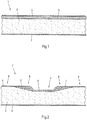
In der
Zwischen der Kernlage 2 und der inneren Decklage 4 ist eine Verbundschicht 5 vorgesehen, die aus Glasfaserhäckseln und einem Polyurethanmaterial besteht. Das Polyurethanmaterial ist, anders als bei der Kernlage 2, nicht geschäumt. In das Polyurethanmaterial sind stattdessen die Glasfaserhäcksel gleichmäßig eingearbeitet. Die Verbundschicht 5 weist zu etwa 60 Gew.-% bis 80 Gew.-% Polyurethanmaterial und zu etwa 20 Gew.-% bis 40 Gew.-% Glasfaserhäcksel auf. Vorzugsweise sind keine nennenswerten Anteile weiterer Komponenten in der Verbundschicht 5 vorhanden.Between the
Zur Herstellung der Verbundschicht 5 sind das Polyurethanmaterial und die Glasfaserhäcksel mit separaten Düsen auf die Innenseite der inneren Decklage 4 aufgesprüht worden. Durch das Aufsprühen wird eine gleichmäßige Verteilung der Glasfaserhäcksel als disperse Phase in der Matrix aus Polyurethanmaterial der Verbundschicht 5 als kontinuierliche Phase erreicht. Bevor das Polyurethanmaterial der Verbundschicht 5 ausgehärtet ist, wird der Hohlraum zwischen der so geschaffenen Verbundschicht 5 und der gegenüberliegenden äußeren Decklage 3 ausgeschäumt, und zwar mit dem Polyurethanmaterial der Kernschicht 2. Die beiden Polyurethanmaterialien reagieren dann zusammen und miteinander in Kontakt stehend aus. Auf diese Weise wird eine feste Verbindung zwischen der Kernlage 2 und der Verbundschicht 5 erreicht.For the production of the
In der
Die Schiene 6 ist beim dargestellten und insoweit bevorzugten Paneel 1' bündig in selbiges eingelassen. Dazu ist in die innere Decklage 4' eine Öffnung 7 eingebracht. Es könnte jedoch auch vorgesehen sein, dass in der inneren Decklage eine Vertiefung eingepresst ist, in der die Schiene 6 aufgenommen ist. Umlaufend zu der Schiene 6 ist in den angrenzenden Bereichen 8 der inneren Decklage 4' eine Verbundschicht 5' vorgesehen. In den übrigen Bereichen 9 des Paneels 1' ist jedoch auf eine Verbundschicht verzichtet worden.The
In der
In der
In der
Claims (15)
- Panel (1, 1', 1", 1''') of a box body of a commercial vehicle, in particular a truck, transporter, trailer and/or semitrailer,- having two covering layers (3, 4, 4', 4", 4''') and a core layer (2) which is arranged between the covering layers (3, 4, 4', 4", 4'''),- wherein at least one of the covering layers (3, 4, 4', 4", 4''') is formed from sheet metal, and- wherein the core layer (2) is formed from foamed plastics material,- wherein a composite layer (5, 5', 5", 5''') comprising an unfoamed plastics material and a fibre material is at least partially provided between the core layer (2) and a covering layer (3, 4, 4', 4", 4''') which is formed from sheet metal,characterised in that the fibre material is distributed as a disperse phase in a uniform manner in a matrix of the plastics material as a continuous phase and in that the composite layer (5, 5', 5", 5''') and the core layer (2) are connected to each other with an additional adhesive bonding being dispensed with.
- Panel according to claim 1,
characterised in that the unfoamed plastics material of the composite layer (5, 5', 5", 5''') is formed from a polyurethane material. - Panel according to claim 1 or 2,
characterised in that the core layer (2) is formed from foamed polyurethane material. - Panel according to any one of claims 1 to 3,
characterised in that
the composite layer (5, 5') and the foamed plastics material of the core layer (2) are applied to each other wet-on-wet and subsequently cured. - Panel according to any one of claims 1 to 3,
characterised in that
the plastics material of the core layer (2) which is intended to be foamed is applied to the already-cured composite layer (5", 5''') and is subsequently cured. - Panel according to any one of claims 1 to 5,
characterised in that
the fibre material of the composite layer (5, 5', 5", 5''') is a glass fibre material. - Panel according to claim 6,
characterised in that
the glass fibre material is shredded glass fibre. - Panel according to any one of claims 1 to 7,
characterised in that
the proportion of the unfoamed plastics material of the composite layer (5, 5', 5", 5''') is at least 50% by weight, preferably at least 60% by weight, in particular between 60% by weight and 80% by weight, with respect to the panel comprising the covering layers (3, 4, 4', 4", 4'''), the composite layer (5, 5', 5", 5''') and the core layer (2). - Panel according to any one of claims 1 to 8,
characterised in that
the composite layer (5', 5", 5''') is provided only in zones of increased mechanical loads, such as, for instance, in the region (8) of at least one load securing device, in particular a load securing rail (6), and/or in the region (8") of at least one double-deck rail (6). - Panel according to claim 9,
characterised in that
the composite layer (5''') is provided in the region (8') of a skirting board (14) and/or a supplementary skirting board. - Panel according to claim 9 or 10,
characterised in that
the edges (12, 13) of the composite layer (5', 5", 5''') which is provided only partially are constructed in a substantially undulating and/or curved manner. - Panel according to any one of claims 1 to 11,
characterised in that
the composite layer (5, 5'') is provided in multiple layers over the complete surface and/or only partially. - Panel according to any one of claims 1 to 12,
characterised in that
the metal sheet of the covering layer (4, 4", 4''') which is associated with the composite layer (5, 5', 5", 5''') is less than 0.7 mm, preferably less than 0.55 mm, thick. - Panel according to any one of claims 1 to 13,
characterised in that
a composite layer is at least partially provided between the core layer and both covering layers. - Panel according to claim 14,
characterised in that
the composite layers are constructed in an identical manner with respect to their composition.
Priority Applications (1)
| Application Number | Priority Date | Filing Date | Title |
|---|---|---|---|
| EP10164607.3A EP2392453B2 (en) | 2010-06-01 | 2010-06-01 | Panel of a vehicle load compartment |
Applications Claiming Priority (1)
| Application Number | Priority Date | Filing Date | Title |
|---|---|---|---|
| EP10164607.3A EP2392453B2 (en) | 2010-06-01 | 2010-06-01 | Panel of a vehicle load compartment |
Publications (3)
| Publication Number | Publication Date |
|---|---|
| EP2392453A1 EP2392453A1 (en) | 2011-12-07 |
| EP2392453B1 true EP2392453B1 (en) | 2017-11-29 |
| EP2392453B2 EP2392453B2 (en) | 2023-09-13 |
Family
ID=42664833
Family Applications (1)
| Application Number | Title | Priority Date | Filing Date |
|---|---|---|---|
| EP10164607.3A Active EP2392453B2 (en) | 2010-06-01 | 2010-06-01 | Panel of a vehicle load compartment |
Country Status (1)
| Country | Link |
|---|---|
| EP (1) | EP2392453B2 (en) |
Families Citing this family (5)
| Publication number | Priority date | Publication date | Assignee | Title |
|---|---|---|---|---|
| US9676549B2 (en) | 2014-12-02 | 2017-06-13 | Fontaine Commercial Trailer, Inc. | Floor assembly for transportable refrigerated container |
| DE102017100756A1 (en) | 2017-01-16 | 2018-07-19 | Logis AG | Power and commercial vehicle support device |
| EP3590799A1 (en) * | 2018-07-06 | 2020-01-08 | Schmitz Cargobull AG | Wall element of a box body with base board and box body |
| EP3726070B1 (en) | 2019-04-18 | 2021-10-06 | Schmitz Cargobull AG | Structure for a commercial vehicle and method for fixing a component |
| EP4086144A1 (en) * | 2021-05-07 | 2022-11-09 | Schmitz Cargobull AG | Commercial vehicle panel with fibre-reinforced plastic layer and commercial vehicle with corresponding commercial vehicle panel |
Citations (3)
| Publication number | Priority date | Publication date | Assignee | Title |
|---|---|---|---|---|
| GB2211780A (en) * | 1987-10-31 | 1989-07-12 | Btr Plc | Moulding a recess at an unreinforced location, of a G.R.P. panel incorporating reinforcing sheets |
| WO2000047401A1 (en) | 1999-02-10 | 2000-08-17 | Warrington Vehicle Centre Limited | Insulating material |
| DE102007051129A1 (en) * | 2007-10-24 | 2009-04-30 | Bayer Materialscience Ag | Apparatus and method for producing reinforced polyurethane composite materials |
Family Cites Families (2)
| Publication number | Priority date | Publication date | Assignee | Title |
|---|---|---|---|---|
| US4459334A (en) * | 1981-10-08 | 1984-07-10 | Rmax, Inc. | Composite building panel |
| US7025408B2 (en) * | 2003-08-20 | 2006-04-11 | Great Dane Limited Partnership | Liner panel having barrier layer |
-
2010
- 2010-06-01 EP EP10164607.3A patent/EP2392453B2/en active Active
Patent Citations (3)
| Publication number | Priority date | Publication date | Assignee | Title |
|---|---|---|---|---|
| GB2211780A (en) * | 1987-10-31 | 1989-07-12 | Btr Plc | Moulding a recess at an unreinforced location, of a G.R.P. panel incorporating reinforcing sheets |
| WO2000047401A1 (en) | 1999-02-10 | 2000-08-17 | Warrington Vehicle Centre Limited | Insulating material |
| DE102007051129A1 (en) * | 2007-10-24 | 2009-04-30 | Bayer Materialscience Ag | Apparatus and method for producing reinforced polyurethane composite materials |
Non-Patent Citations (5)
| Title |
|---|
| "A Cost-effective Hand-operated Polyurethane-Composite-Spray-Moulding Technology from Hennecke - SpecialChem - cost effective hand operated polyurethane composite spray moulding technology from hennecke", 1 July 2009 (2009-07-01), pages 1 - 1, XP055156438, Retrieved from the Internet <URL:http://polymer-additives.specialchem.com/news/industry-news/a-cost-effective-hand-operated-polyurethane-composite-spray-moulding-technology-from-hennecke> [retrieved on 20141203] * |
| A COST-EFFECTIVE HAND-OPERATED POLYURETHANE-COMPOSITE-SPRAY-MOULDING TECHNOLOGY FROM HENNECKE-SPECIALCHEM ... |
| F.C. CAMPBELL: "Manufacturing Processes for Advanced Composites", 1 January 2004 (2004-01-01), pages 17 - 25, XP055209137, ISBN: 978-1-85-617415-2, Retrieved from the Internet <URL:http://lib.myilibrary.com?ID=104809> [retrieved on 20150824] * |
| JIM RILEY ET AL: "NEW DEVELOPMENTS IN PUR COMPOSITE SPRAY MOLDING PUR-CSM TECHNOLOGY FOR MULTIPLE PROCESSES", 7 August 2006 (2006-08-07), XP055156451, Retrieved from the Internet <URL:http://speautomotive.com/SPEA_CD/SPEA2006/PDF/d/d3.pdf> [retrieved on 20141203] * |
| JIM RILEY, NEW DEVELOPMENTS IN PUR COMPOSITE SPRAY MOLDING PUR-CSM TECHNOLOGY FOR MULTIPLE PROCESSES |
Also Published As
| Publication number | Publication date |
|---|---|
| EP2392453B2 (en) | 2023-09-13 |
| EP2392453A1 (en) | 2011-12-07 |
Similar Documents
| Publication | Publication Date | Title |
|---|---|---|
| EP2392453B1 (en) | Panel of a vehicle load compartment | |
| EP2881310B1 (en) | Body for a utility vehicle with a multi-layer panel | |
| WO2008138626A1 (en) | Transport container | |
| EP0846069B1 (en) | Profile sections for plate-like composite elements | |
| EP3116806B1 (en) | Bottom plate for a freight pallet, method for producing a corresponding bottom plate, method for producing a bottom element | |
| EP2116456B1 (en) | Base element for a vehicle, such as a goods vehicle, semi-trailer or trailer | |
| EP0901939B1 (en) | Tipper floor | |
| EP3584145A1 (en) | Panel and assembly of a commercial vehicle for refrigerated transport | |
| EP3090926B1 (en) | Floor of a structure of a commercial vehicle | |
| EP2789501B1 (en) | Commercial vehicle floor with slip-resistant plastic film | |
| EP2116453B1 (en) | Cross member for a base element of a vehicle, such as a lorry trailer, semi-trailer or trailer, and base element with such a cross member | |
| WO2016091280A1 (en) | Insulating panel for a commercial vehicle structure, and commercial vehicle comprising a commercial vehicle structure | |
| EP2123542B1 (en) | Floor element for a vehicle, such as a lorry, semi-trailer or trailer | |
| EP2116452A1 (en) | Base element and connection between a base element and a side wall of a box body for an automobile | |
| EP3744617B1 (en) | Chassis of a commercial vehicle with longitudinal beams and cross beams | |
| EP3388317B1 (en) | Refrigeration vehicle structure | |
| EP2116462B9 (en) | Side wall element and connection between a side wall element and a base element of a box body for an automobile | |
| EP2116459B1 (en) | Method for producing a floor element for a vehicle, such as a heavy goods vehicle, semi-trailer or trailer | |
| DE102014113822A1 (en) | Utility vehicle with a support beam having soil structure | |
| EP3431280B1 (en) | Luggage structure for a commercial vehicle | |
| DE4331836C2 (en) | Base plate for air freight containers or pallets | |
| EP3590797A1 (en) | Box body with a wall connected to a floor structure | |
| DE19814275B4 (en) | fifth wheel | |
| DE102017115419A1 (en) | Vehicle body with sliding belt unit | |
| DE202008009748U1 (en) | sandwich panel |
Legal Events
| Date | Code | Title | Description |
|---|---|---|---|
| 17P | Request for examination filed |
Effective date: 20110831 |
|
| AK | Designated contracting states |
Kind code of ref document: A1 Designated state(s): AL AT BE BG CH CY CZ DE DK EE ES FI FR GB GR HR HU IE IS IT LI LT LU LV MC MK MT NL NO PL PT RO SE SI SK SM TR |
|
| AX | Request for extension of the european patent |
Extension state: BA ME RS |
|
| PUAI | Public reference made under article 153(3) epc to a published international application that has entered the european phase |
Free format text: ORIGINAL CODE: 0009012 |
|
| RIN1 | Information on inventor provided before grant (corrected) |
Inventor name: DAHLHAUS, ANDREAS Inventor name: BEELMANN, REINHARD |
|
| 17Q | First examination report despatched |
Effective date: 20120824 |
|
| REG | Reference to a national code |
Ref country code: DE Ref legal event code: R079 Ref document number: 502010014418 Country of ref document: DE Free format text: PREVIOUS MAIN CLASS: B32B0005180000 Ipc: B32B0005200000 |
|
| RIC1 | Information provided on ipc code assigned before grant |
Ipc: B32B 5/20 20060101AFI20170125BHEP Ipc: B62D 29/00 20060101ALI20170125BHEP Ipc: B32B 27/06 20060101ALI20170125BHEP Ipc: B32B 15/08 20060101ALI20170125BHEP Ipc: B62D 33/04 20060101ALI20170125BHEP Ipc: B32B 27/40 20060101ALI20170125BHEP |
|
| GRAJ | Information related to disapproval of communication of intention to grant by the applicant or resumption of examination proceedings by the epo deleted |
Free format text: ORIGINAL CODE: EPIDOSDIGR1 |
|
| STAA | Information on the status of an ep patent application or granted ep patent |
Free format text: STATUS: GRANT OF PATENT IS INTENDED |
|
| GRAP | Despatch of communication of intention to grant a patent |
Free format text: ORIGINAL CODE: EPIDOSNIGR1 |
|
| INTG | Intention to grant announced |
Effective date: 20170609 |
|
| GRAS | Grant fee paid |
Free format text: ORIGINAL CODE: EPIDOSNIGR3 |
|
| GRAA | (expected) grant |
Free format text: ORIGINAL CODE: 0009210 |
|
| STAA | Information on the status of an ep patent application or granted ep patent |
Free format text: STATUS: THE PATENT HAS BEEN GRANTED |
|
| AK | Designated contracting states |
Kind code of ref document: B1 Designated state(s): AL AT BE BG CH CY CZ DE DK EE ES FI FR GB GR HR HU IE IS IT LI LT LU LV MC MK MT NL NO PL PT RO SE SI SK SM TR |
|
| RIN1 | Information on inventor provided before grant (corrected) |
Inventor name: BEELMANN, REINHARD Inventor name: DAHLHAUS, ANDREAS |
|
| REG | Reference to a national code |
Ref country code: CH Ref legal event code: EP |
|
| REG | Reference to a national code |
Ref country code: AT Ref legal event code: REF Ref document number: 950007 Country of ref document: AT Kind code of ref document: T Effective date: 20171215 |
|
| REG | Reference to a national code |
Ref country code: IE Ref legal event code: FG4D Free format text: LANGUAGE OF EP DOCUMENT: GERMAN |
|
| REG | Reference to a national code |
Ref country code: DE Ref legal event code: R096 Ref document number: 502010014418 Country of ref document: DE |
|
| REG | Reference to a national code |
Ref country code: NL Ref legal event code: MP Effective date: 20171129 |
|
| REG | Reference to a national code |
Ref country code: LT Ref legal event code: MG4D |
|
| PG25 | Lapsed in a contracting state [announced via postgrant information from national office to epo] |
Ref country code: ES Free format text: LAPSE BECAUSE OF FAILURE TO SUBMIT A TRANSLATION OF THE DESCRIPTION OR TO PAY THE FEE WITHIN THE PRESCRIBED TIME-LIMIT Effective date: 20171129 Ref country code: FI Free format text: LAPSE BECAUSE OF FAILURE TO SUBMIT A TRANSLATION OF THE DESCRIPTION OR TO PAY THE FEE WITHIN THE PRESCRIBED TIME-LIMIT Effective date: 20171129 Ref country code: NO Free format text: LAPSE BECAUSE OF FAILURE TO SUBMIT A TRANSLATION OF THE DESCRIPTION OR TO PAY THE FEE WITHIN THE PRESCRIBED TIME-LIMIT Effective date: 20180228 Ref country code: LT Free format text: LAPSE BECAUSE OF FAILURE TO SUBMIT A TRANSLATION OF THE DESCRIPTION OR TO PAY THE FEE WITHIN THE PRESCRIBED TIME-LIMIT Effective date: 20171129 Ref country code: SE Free format text: LAPSE BECAUSE OF FAILURE TO SUBMIT A TRANSLATION OF THE DESCRIPTION OR TO PAY THE FEE WITHIN THE PRESCRIBED TIME-LIMIT Effective date: 20171129 |
|
| PG25 | Lapsed in a contracting state [announced via postgrant information from national office to epo] |
Ref country code: BG Free format text: LAPSE BECAUSE OF FAILURE TO SUBMIT A TRANSLATION OF THE DESCRIPTION OR TO PAY THE FEE WITHIN THE PRESCRIBED TIME-LIMIT Effective date: 20180228 Ref country code: LV Free format text: LAPSE BECAUSE OF FAILURE TO SUBMIT A TRANSLATION OF THE DESCRIPTION OR TO PAY THE FEE WITHIN THE PRESCRIBED TIME-LIMIT Effective date: 20171129 Ref country code: HR Free format text: LAPSE BECAUSE OF FAILURE TO SUBMIT A TRANSLATION OF THE DESCRIPTION OR TO PAY THE FEE WITHIN THE PRESCRIBED TIME-LIMIT Effective date: 20171129 Ref country code: GR Free format text: LAPSE BECAUSE OF FAILURE TO SUBMIT A TRANSLATION OF THE DESCRIPTION OR TO PAY THE FEE WITHIN THE PRESCRIBED TIME-LIMIT Effective date: 20180301 |
|
| REG | Reference to a national code |
Ref country code: FR Ref legal event code: PLFP Year of fee payment: 9 |
|
| PG25 | Lapsed in a contracting state [announced via postgrant information from national office to epo] |
Ref country code: NL Free format text: LAPSE BECAUSE OF FAILURE TO SUBMIT A TRANSLATION OF THE DESCRIPTION OR TO PAY THE FEE WITHIN THE PRESCRIBED TIME-LIMIT Effective date: 20171129 |
|
| PG25 | Lapsed in a contracting state [announced via postgrant information from national office to epo] |
Ref country code: EE Free format text: LAPSE BECAUSE OF FAILURE TO SUBMIT A TRANSLATION OF THE DESCRIPTION OR TO PAY THE FEE WITHIN THE PRESCRIBED TIME-LIMIT Effective date: 20171129 Ref country code: DK Free format text: LAPSE BECAUSE OF FAILURE TO SUBMIT A TRANSLATION OF THE DESCRIPTION OR TO PAY THE FEE WITHIN THE PRESCRIBED TIME-LIMIT Effective date: 20171129 Ref country code: SK Free format text: LAPSE BECAUSE OF FAILURE TO SUBMIT A TRANSLATION OF THE DESCRIPTION OR TO PAY THE FEE WITHIN THE PRESCRIBED TIME-LIMIT Effective date: 20171129 Ref country code: CZ Free format text: LAPSE BECAUSE OF FAILURE TO SUBMIT A TRANSLATION OF THE DESCRIPTION OR TO PAY THE FEE WITHIN THE PRESCRIBED TIME-LIMIT Effective date: 20171129 Ref country code: CY Free format text: LAPSE BECAUSE OF FAILURE TO SUBMIT A TRANSLATION OF THE DESCRIPTION OR TO PAY THE FEE WITHIN THE PRESCRIBED TIME-LIMIT Effective date: 20171129 |
|
| REG | Reference to a national code |
Ref country code: DE Ref legal event code: R026 Ref document number: 502010014418 Country of ref document: DE |
|
| PG25 | Lapsed in a contracting state [announced via postgrant information from national office to epo] |
Ref country code: PL Free format text: LAPSE BECAUSE OF FAILURE TO SUBMIT A TRANSLATION OF THE DESCRIPTION OR TO PAY THE FEE WITHIN THE PRESCRIBED TIME-LIMIT Effective date: 20171129 Ref country code: RO Free format text: LAPSE BECAUSE OF FAILURE TO SUBMIT A TRANSLATION OF THE DESCRIPTION OR TO PAY THE FEE WITHIN THE PRESCRIBED TIME-LIMIT Effective date: 20171129 Ref country code: SM Free format text: LAPSE BECAUSE OF FAILURE TO SUBMIT A TRANSLATION OF THE DESCRIPTION OR TO PAY THE FEE WITHIN THE PRESCRIBED TIME-LIMIT Effective date: 20171129 Ref country code: IT Free format text: LAPSE BECAUSE OF FAILURE TO SUBMIT A TRANSLATION OF THE DESCRIPTION OR TO PAY THE FEE WITHIN THE PRESCRIBED TIME-LIMIT Effective date: 20171129 |
|
| PLBI | Opposition filed |
Free format text: ORIGINAL CODE: 0009260 |
|
| PLAX | Notice of opposition and request to file observation + time limit sent |
Free format text: ORIGINAL CODE: EPIDOSNOBS2 |
|
| PG25 | Lapsed in a contracting state [announced via postgrant information from national office to epo] |
Ref country code: MT Free format text: LAPSE BECAUSE OF FAILURE TO SUBMIT A TRANSLATION OF THE DESCRIPTION OR TO PAY THE FEE WITHIN THE PRESCRIBED TIME-LIMIT Effective date: 20171129 |
|
| 26 | Opposition filed |
Opponent name: FAHRZEUGWERK BERNARD KRONE GMBH & CO. KG Effective date: 20180829 |
|
| PG25 | Lapsed in a contracting state [announced via postgrant information from national office to epo] |
Ref country code: SI Free format text: LAPSE BECAUSE OF FAILURE TO SUBMIT A TRANSLATION OF THE DESCRIPTION OR TO PAY THE FEE WITHIN THE PRESCRIBED TIME-LIMIT Effective date: 20171129 |
|
| PLBB | Reply of patent proprietor to notice(s) of opposition received |
Free format text: ORIGINAL CODE: EPIDOSNOBS3 |
|
| REG | Reference to a national code |
Ref country code: CH Ref legal event code: PL |
|
| GBPC | Gb: european patent ceased through non-payment of renewal fee |
Effective date: 20180601 |
|
| REG | Reference to a national code |
Ref country code: BE Ref legal event code: MM Effective date: 20180630 |
|
| REG | Reference to a national code |
Ref country code: IE Ref legal event code: MM4A |
|
| PG25 | Lapsed in a contracting state [announced via postgrant information from national office to epo] |
Ref country code: MC Free format text: LAPSE BECAUSE OF FAILURE TO SUBMIT A TRANSLATION OF THE DESCRIPTION OR TO PAY THE FEE WITHIN THE PRESCRIBED TIME-LIMIT Effective date: 20171129 Ref country code: LU Free format text: LAPSE BECAUSE OF NON-PAYMENT OF DUE FEES Effective date: 20180601 |
|
| PG25 | Lapsed in a contracting state [announced via postgrant information from national office to epo] |
Ref country code: GB Free format text: LAPSE BECAUSE OF NON-PAYMENT OF DUE FEES Effective date: 20180601 Ref country code: CH Free format text: LAPSE BECAUSE OF NON-PAYMENT OF DUE FEES Effective date: 20180630 Ref country code: LI Free format text: LAPSE BECAUSE OF NON-PAYMENT OF DUE FEES Effective date: 20180630 Ref country code: IE Free format text: LAPSE BECAUSE OF NON-PAYMENT OF DUE FEES Effective date: 20180601 |
|
| PG25 | Lapsed in a contracting state [announced via postgrant information from national office to epo] |
Ref country code: BE Free format text: LAPSE BECAUSE OF NON-PAYMENT OF DUE FEES Effective date: 20180630 |
|
| REG | Reference to a national code |
Ref country code: AT Ref legal event code: MM01 Ref document number: 950007 Country of ref document: AT Kind code of ref document: T Effective date: 20180601 |
|
| PG25 | Lapsed in a contracting state [announced via postgrant information from national office to epo] |
Ref country code: AT Free format text: LAPSE BECAUSE OF NON-PAYMENT OF DUE FEES Effective date: 20180601 |
|
| PG25 | Lapsed in a contracting state [announced via postgrant information from national office to epo] |
Ref country code: TR Free format text: LAPSE BECAUSE OF FAILURE TO SUBMIT A TRANSLATION OF THE DESCRIPTION OR TO PAY THE FEE WITHIN THE PRESCRIBED TIME-LIMIT Effective date: 20171129 |
|
| PG25 | Lapsed in a contracting state [announced via postgrant information from national office to epo] |
Ref country code: HU Free format text: LAPSE BECAUSE OF FAILURE TO SUBMIT A TRANSLATION OF THE DESCRIPTION OR TO PAY THE FEE WITHIN THE PRESCRIBED TIME-LIMIT; INVALID AB INITIO Effective date: 20100601 Ref country code: PT Free format text: LAPSE BECAUSE OF FAILURE TO SUBMIT A TRANSLATION OF THE DESCRIPTION OR TO PAY THE FEE WITHIN THE PRESCRIBED TIME-LIMIT Effective date: 20171129 |
|
| PG25 | Lapsed in a contracting state [announced via postgrant information from national office to epo] |
Ref country code: MK Free format text: LAPSE BECAUSE OF NON-PAYMENT OF DUE FEES Effective date: 20171129 |
|
| PG25 | Lapsed in a contracting state [announced via postgrant information from national office to epo] |
Ref country code: AL Free format text: LAPSE BECAUSE OF FAILURE TO SUBMIT A TRANSLATION OF THE DESCRIPTION OR TO PAY THE FEE WITHIN THE PRESCRIBED TIME-LIMIT Effective date: 20171129 Ref country code: IS Free format text: LAPSE BECAUSE OF FAILURE TO SUBMIT A TRANSLATION OF THE DESCRIPTION OR TO PAY THE FEE WITHIN THE PRESCRIBED TIME-LIMIT Effective date: 20180329 |
|
| PLAB | Opposition data, opponent's data or that of the opponent's representative modified |
Free format text: ORIGINAL CODE: 0009299OPPO |
|
| R26 | Opposition filed (corrected) |
Opponent name: FAHRZEUGWERK BERNARD KRONE GMBH & CO. KG Effective date: 20180829 |
|
| P01 | Opt-out of the competence of the unified patent court (upc) registered |
Effective date: 20230517 |
|
| PGFP | Annual fee paid to national office [announced via postgrant information from national office to epo] |
Ref country code: FR Payment date: 20230622 Year of fee payment: 14 Ref country code: DE Payment date: 20230622 Year of fee payment: 14 |
|
| PUAH | Patent maintained in amended form |
Free format text: ORIGINAL CODE: 0009272 |
|
| STAA | Information on the status of an ep patent application or granted ep patent |
Free format text: STATUS: PATENT MAINTAINED AS AMENDED |
|
| 27A | Patent maintained in amended form |
Effective date: 20230913 |
|
| AK | Designated contracting states |
Kind code of ref document: B2 Designated state(s): AL AT BE BG CH CY CZ DE DK EE ES FI FR GB GR HR HU IE IS IT LI LT LU LV MC MK MT NL NO PL PT RO SE SI SK SM TR |
|
| REG | Reference to a national code |
Ref country code: DE Ref legal event code: R102 Ref document number: 502010014418 Country of ref document: DE |