EP2391796B1 - Barrière annulaire et système à barrière annulaire - Google Patents
Barrière annulaire et système à barrière annulaire Download PDFInfo
- Publication number
- EP2391796B1 EP2391796B1 EP10700124.0A EP10700124A EP2391796B1 EP 2391796 B1 EP2391796 B1 EP 2391796B1 EP 10700124 A EP10700124 A EP 10700124A EP 2391796 B1 EP2391796 B1 EP 2391796B1
- Authority
- EP
- European Patent Office
- Prior art keywords
- annular barrier
- tubular structure
- fluid
- tool
- sleeve
- Prior art date
- Legal status (The legal status is an assumption and is not a legal conclusion. Google has not performed a legal analysis and makes no representation as to the accuracy of the status listed.)
- Not-in-force
Links
- 230000004888 barrier function Effects 0.000 title claims description 198
- 239000012530 fluid Substances 0.000 claims description 95
- 238000004519 manufacturing process Methods 0.000 claims description 41
- 238000007789 sealing Methods 0.000 claims description 22
- 238000002955 isolation Methods 0.000 claims description 15
- 239000000463 material Substances 0.000 claims description 7
- 238000000034 method Methods 0.000 claims description 6
- 239000004568 cement Substances 0.000 description 19
- 230000015572 biosynthetic process Effects 0.000 description 10
- 150000001875 compounds Chemical class 0.000 description 9
- 239000002184 metal Substances 0.000 description 7
- 229920000642 polymer Polymers 0.000 description 6
- XLYOFNOQVPJJNP-UHFFFAOYSA-N water Substances O XLYOFNOQVPJJNP-UHFFFAOYSA-N 0.000 description 6
- 239000000243 solution Substances 0.000 description 4
- 238000004891 communication Methods 0.000 description 3
- 229920001971 elastomer Polymers 0.000 description 3
- 239000013536 elastomeric material Substances 0.000 description 3
- 239000007789 gas Substances 0.000 description 3
- 238000005259 measurement Methods 0.000 description 3
- 229920001296 polysiloxane Polymers 0.000 description 3
- 238000004873 anchoring Methods 0.000 description 2
- 238000005452 bending Methods 0.000 description 2
- 238000007373 indentation Methods 0.000 description 2
- 238000003825 pressing Methods 0.000 description 2
- 238000003466 welding Methods 0.000 description 2
- 239000003795 chemical substances by application Substances 0.000 description 1
- 239000000356 contaminant Substances 0.000 description 1
- 230000003247 decreasing effect Effects 0.000 description 1
- 239000000835 fiber Substances 0.000 description 1
- 239000012634 fragment Substances 0.000 description 1
- 238000002347 injection Methods 0.000 description 1
- 239000007924 injection Substances 0.000 description 1
- 238000003780 insertion Methods 0.000 description 1
- 230000037431 insertion Effects 0.000 description 1
- 238000002156 mixing Methods 0.000 description 1
- 238000012986 modification Methods 0.000 description 1
- 230000004048 modification Effects 0.000 description 1
- 239000002245 particle Substances 0.000 description 1
- 239000000843 powder Substances 0.000 description 1
- 239000013535 sea water Substances 0.000 description 1
- 239000003566 sealing material Substances 0.000 description 1
- 238000012360 testing method Methods 0.000 description 1
- 210000002105 tongue Anatomy 0.000 description 1
- 230000007704 transition Effects 0.000 description 1
- 239000002349 well water Substances 0.000 description 1
Images


Classifications
-
- E—FIXED CONSTRUCTIONS
- E21—EARTH DRILLING; MINING
- E21B—EARTH DRILLING, e.g. DEEP DRILLING; OBTAINING OIL, GAS, WATER, SOLUBLE OR MELTABLE MATERIALS OR A SLURRY OF MINERALS FROM WELLS
- E21B33/00—Sealing or packing boreholes or wells
- E21B33/10—Sealing or packing boreholes or wells in the borehole
- E21B33/12—Packers; Plugs
- E21B33/127—Packers; Plugs with inflatable sleeve
- E21B33/1277—Packers; Plugs with inflatable sleeve characterised by the construction or fixation of the sleeve
-
- E—FIXED CONSTRUCTIONS
- E21—EARTH DRILLING; MINING
- E21B—EARTH DRILLING, e.g. DEEP DRILLING; OBTAINING OIL, GAS, WATER, SOLUBLE OR MELTABLE MATERIALS OR A SLURRY OF MINERALS FROM WELLS
- E21B33/00—Sealing or packing boreholes or wells
- E21B33/10—Sealing or packing boreholes or wells in the borehole
- E21B33/12—Packers; Plugs
- E21B33/1208—Packers; Plugs characterised by the construction of the sealing or packing means
-
- E—FIXED CONSTRUCTIONS
- E21—EARTH DRILLING; MINING
- E21B—EARTH DRILLING, e.g. DEEP DRILLING; OBTAINING OIL, GAS, WATER, SOLUBLE OR MELTABLE MATERIALS OR A SLURRY OF MINERALS FROM WELLS
- E21B33/00—Sealing or packing boreholes or wells
- E21B33/10—Sealing or packing boreholes or wells in the borehole
- E21B33/12—Packers; Plugs
- E21B33/128—Packers; Plugs with a member expanded radially by axial pressure
- E21B33/1285—Packers; Plugs with a member expanded radially by axial pressure by fluid pressure
-
- E—FIXED CONSTRUCTIONS
- E21—EARTH DRILLING; MINING
- E21B—EARTH DRILLING, e.g. DEEP DRILLING; OBTAINING OIL, GAS, WATER, SOLUBLE OR MELTABLE MATERIALS OR A SLURRY OF MINERALS FROM WELLS
- E21B34/00—Valve arrangements for boreholes or wells
- E21B34/06—Valve arrangements for boreholes or wells in wells
- E21B34/10—Valve arrangements for boreholes or wells in wells operated by control fluid supplied from outside the borehole
-
- E—FIXED CONSTRUCTIONS
- E21—EARTH DRILLING; MINING
- E21B—EARTH DRILLING, e.g. DEEP DRILLING; OBTAINING OIL, GAS, WATER, SOLUBLE OR MELTABLE MATERIALS OR A SLURRY OF MINERALS FROM WELLS
- E21B34/00—Valve arrangements for boreholes or wells
- E21B34/06—Valve arrangements for boreholes or wells in wells
- E21B34/14—Valve arrangements for boreholes or wells in wells operated by movement of tools, e.g. sleeve valves operated by pistons or wire line tools
-
- E—FIXED CONSTRUCTIONS
- E21—EARTH DRILLING; MINING
- E21B—EARTH DRILLING, e.g. DEEP DRILLING; OBTAINING OIL, GAS, WATER, SOLUBLE OR MELTABLE MATERIALS OR A SLURRY OF MINERALS FROM WELLS
- E21B43/00—Methods or apparatus for obtaining oil, gas, water, soluble or meltable materials or a slurry of minerals from wells
- E21B43/02—Subsoil filtering
- E21B43/10—Setting of casings, screens, liners or the like in wells
- E21B43/103—Setting of casings, screens, liners or the like in wells of expandable casings, screens, liners, or the like
- E21B43/105—Expanding tools specially adapted therefor
Definitions
- the present invention relates to an annular barrier system for expanding an annular barrier in an annulus between a well tubular structure and an inside wall of a borehole or a well downhole, e.g. to seal off the annulus.
- the annular barrier system comprises an annular barrier having a tubular part for mounting as part of the well tubular structure, the annular barrier further comprising an expandable sleeve surrounding the tubular part, at least one end of the expandable sleeve being fastened by various fastening means to the tubular part.
- annular barriers are used for different purposes, such as for providing a barrier to flow between an inner and an outer tubular structure or an inner tubular structure and the inner wall of the borehole.
- the annular barriers are mounted as part of the well tubular structure.
- An annular barrier has an inner wall surrounded by an annular expandable sleeve.
- the expandable sleeve is typically made of an elastomeric material, but may also be made of metal. The sleeve is fastened at its ends to the inner wall of the annular barrier.
- a second annular barrier In order to seal off a zone between an inner and an outer tubular structure or a well tubular structure and the borehole, a second annular barrier is used.
- the first annular barrier is expanded at one side of the zone to be sealed off and the second annular barrier is expanded at the other side of that zone.
- the zone is sealed off.
- An annular barrier is known from the closest prior art US 7,306,033 .
- annular barrier having an expandable metal sleeve is known from US 6,640,893 B1 .
- the inner wall of the annular barrier and the enclosing expandable sleeve form a chamber.
- the chamber is prefilled with hardening cement through openings in the inner wall of the annular barrier. This is performed in order to prevent fluid flowing inside the well tubular structure during production from entering the openings and thus the chamber.
- the sleeve is expanded by injecting a second cement compound into the chamber through the openings and thus expanding the sleeve by breaking the hardened cement.
- the second cement compound would be diluted and thus be unable to harden subsequently.
- the well tubular structure is closed off at the end most distant from the surface and the well tubular structure is filled with the second cement compound.
- annular barriers When mounting the well tubular structure string, annular barriers can be inserted at regular intervals. Some annular barriers may be used to fasten or centralise the well tubular structure string in the borehole, whereas others await a later use, such as sealing off a zone. Cement prefilled in the chambers may thus have to wait for expansion at the risk of losing its properties before use.
- first cement compound may close the opening so that the opening has to be cleaned before injecting the second cement compound.
- the opening may also be filled with contaminants or fragments comprised in the fluid running in the well tubular structure during production.
- annular barrier system for expanding an annular barrier in an annulus between a well tubular structure and an inside wall of a borehole downhole, comprising:
- the annular barrier may have a valve for controlling the passage of pressurised fluid into the space between the expandable sleeve and the tubular part.
- the sleeve may have two ends made of a different material than a centre part of the sleeve.
- the two ends may have an inclined surface corresponding to an inclined surface of the centre part of the sleeve.
- valve may be positioned in at least one of the connection parts.
- valve may be a three-way valve for, in a first position, letting fluid into the space between the expandable sleeve and the tubular part, in a second position letting fluid into the annulus between the well tubular structure and the borehole, and in a third position stopping the fluid from flowing.
- valve in a first position may let fluid into the space between the expandable sleeve and the tubular part, in a second position lets fluid into the annulus between the well tubular structure and the borehole, in a third position stops the fluid from flowing, and in a fourth position lets fluid flow between the annulus and the space.
- the tool may have means for adjusting the valve from one position to another.
- the tool may have packers for closing an annular area.
- the tool may have an isolation device for isolating a first section between an outside wall of the tool and an inside wall of the well tubular structure outside the passage of the tubular part.
- the isolation device of the tool may have at least one sealing means for sealing against the inside wall of the well tubular structure on each side of the valve in order to isolate the first section inside the well tubular structure.
- the tool may have means for connecting to a drill pipe.
- the present invention furthermore relates to an expansion method for expanding an annular barrier as described above inside a borehole comprising a well fluid having a pressure, the method comprising the steps of:
- the present invention relates to a production method for producing oil or the like fluid through a well tubular structure having a production zone in which the well tubular structure has perforations, a screen or the like and at least two annular barriers as described above, comprising the steps of:
- the metal sleeve is expandable from within the tubular structure by means of other fluids than cement as the valve is closed again subsequent to the filling of the space between the sleeve and the tubular structure. If the pressure increases outside the sleeve in the annulus surrounding the sleeve, the valve is reopened by means of a tool, and the pressure in the space increases correspondingly. The expansion of the sleeve is performed by building up a pressure opposite the valve by means of a tool or a drill pipe assembly, or by pressurising the well from above.
- the annular barrier system may further comprise a tool for expanding the expandable sleeve by letting a pressurised fluid through the valve in a passage in the tubular part into the space between the expandable sleeve and the tubular part.
- the tubular part may have a wall thickness
- the connection part may project outwardly from the tubular part, thereby increasing the wall thickness
- tubular part may have a wall thickness
- connection part may comprise a layer on its surface facing the sleeve, thereby increasing its wall thickness
- This layer may be made of a different material than the tubular part and/or the connection part.
- the annular barrier system may comprise at least two annular barriers positioned at a distance from each other along the well tubular structure.
- the at least two annular barriers may be fluidly connected via a fluid connection.
- the fluid connection may be a tube running along a longitudinal extension of the borehole.
- the fluid connection may be a bore within the well tubular structure.
- the pressure delivering means may be a stroker tool.
- the fluid surrounding the tool can be used for injection into the first section.
- the tool may have more than one isolation device.
- the advantage of having more than one isolation device is that it is possible to expand two sleeves at a time or measure at two positions at a time.
- Pressurised fluid delivery could also be facilitated by simply applying pressure to the well tubular structure from the surface via a drill pipe or coiled tubing.
- the tool may have means for connecting to the drill pipe or coiled tubing so that the tool uses the pressurised fluid from drill pipe or coiled tubing.
- the tool may have an anchor tool for anchoring the tool inside the well tubular structure.
- the tool may have means for measuring the flow, temperature, pressure, density, water hold-up, and/or expansion of the sleeve.
- the tool may further have a recording and/or transmitting device for recording and/or transmitting data from measurements performed by the tool.
- the tool may be connected to a downhole tractor in order to move the tool in the well tubular structure.
- the pressurised fluid may be fluid from the well tubular structure or surrounding the well tubular structure, cement, or a polymer, or a combination thereof.
- the tool may comprise a reservoir with the pressurised fluid.
- the invention also relates to an annular barrier comprising a tubular part for mounting as part of a well tubular structure in a borehole, the annular barrier comprising an expandable sleeve surrounding the tubular part, each end of the expandable sleeve being fastened in a fastening means of a connection part in the tubular part, wherein the annular barrier may comprise a valve for controlling a passage of pressurised fluid into a space between the expandable sleeve and the tubular part.
- the valve may be a one-way valve or a two-way valve.
- At least one of the fastening means may be slidable in relation to the connection part of the tubular part of the annular barrier.
- At least one sealing element such as an O-ring, may be arranged between the slidable fastening means and the connection part.
- more than one sealing element may be arranged between the slidable fastening means and the connection part.
- At least one of the fastening means may be fixedly fastened to the connection part or be part of the connection part.
- both of the fastening means may be fixedly fastened with its connection part or be part of its connection part.
- the fastening means may have a projecting edge part which projects outwards from the connecting part.
- Having a part of the fastening means bending outwards means that the fastening means does not have a sharp edge which may cause the sleeve to crack close to the fastening means when expanded.
- the expandable sleeve may be made of metal.
- the expandable sleeve may be made of polymers, such as an elastomeric material, silicone, or natural or syntactic rubber.
- the expandable sleeve may have a thickness of less than 10% of its length.
- the expandable sleeve may be capable of expanding to at least a 10% larger diameter, preferably at least a 15% larger diameter, more preferably at least a 30% larger diameter than that of an unexpanded sleeve.
- the expandable sleeve may have a wall thickness which is thinner than a length of the expandable sleeve, wherein the expandable sleeve may have a thickness of less than 25% of its length, preferably less than 15% of its length, more preferably less than 10% of its length
- the expandable sleeve may have a varying thickness.
- the invention also relates to use of the annular barrier as described above in a well tubular structure for insertion in a borehole.
- the invention relates to a tool as described above.
- the production method may comprise the step of opening a valve in each annular barrier, allowing pressurised fluid to flow from annulus zones adjacent to the production zone into the cavity of the annular barriers.
- the invention relates to a fracturing method for fracturing a formation surrounding a borehole for producing oil or the like fluid through a well tubular structure having a production zone and at least one annular barrier as described above, comprising the following steps:
- the invention relates to a testing method for measuring pressure in a production zone sealed off by two annular barriers as described above, comprising the following steps:
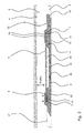
- Annular barriers 1 are typically mounted into the well tubular structure string before lowering the well tubular structure 3 into the borehole downhole.
- the well tubular structure 3 is constructed by well tubular structure parts put together as a long well tubular structure string. Often, the annular barriers 1 are mounted in between the well tubular structure parts when mounting the well tubular structure string.
- the annular barrier 1 is used for a variety of purposes, all of which require that an expandable sleeve 6 of the annular barrier 1 is expanded so that the sleeve abuts the inside wall 4 of the borehole.
- the annular barrier 1 comprises a tubular part 5 which is connected to the well tubular structure 3, as shown in Fig. 1 , e.g. by means of a thread connection 15.
- the tubular part 5 and the well tubular structure part 3 together form the inside wall 16 of the well tubular structure.
- the annular barrier 1 of Fig. 1 is shown in its unexpanded and relaxed position creating a cavity 12 between the expandable sleeve 6 and the tubular part 5 of the annular barrier 1.
- pressurised fluid is injected into the cavity 12 until the expandable sleeve abuts the inside wall 4 of the borehole.
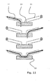
- the annular barrier 1 has a valve 13 which is shown in its closed position.
- This embodiment of the valve 13 has four positions, as shown in Fig. 11 .
- the valve 13 In position A, the valve 13 has an open passage 11 from the inside of the well tubular structure 3 to the space 12 between the expandable sleeve 6 and the tubular part 5 while having a closed passage 21 from the inside of the well tubular structure to the annulus 2 between the outside wall 17 of the well tubular structure and the inside wall 4 of the borehole or formation.
- the valve 13 In position D, the valve 13 has an open passage 11 from the inside of the well tubular structure 3 to the space 12 between the expandable sleeve 6 and the tubular part 5 while also having an open passage 21 from the inside of the well tubular structure to the annulus 2 between the outside wall 17 of the well tubular structure and the inside wall 4 of the borehole or formation.
- the position D results in a fluid connection from the annulus 2 to the space 12.
- valve 13 in the annular barrier 1 enables other fluids than cement, such as the fluid present in the well or sea water, to be used for expanding the expandable sleeve 6 of the annular barrier.
- the expandable sleeve 6 is fastened in a fastening means 8 of a connection part 9 of the annular barrier 1.
- the expandable sleeve 6 is fixedly fastened in the fastening means so that the ends 7 of the expandable sleeve do not move in relation to the fastening means 8.
- the fastening means 8 is a part of the connection part 9.
- the fastening means 8 is fixedly connected to the connection part 9.
- both of the fastening means 8 may be fixedly fastened to its connection part 9 or be a part of its connection part.
- the expandable sleeve 6 is a thin-walled tubular structure inserted into the fastening means 8. Subsequently, the fastening means 8 has been embossed, thereby changing the form of the fastening means and the ends 7 of the expandable sleeve, thus mechanically fastening them in relation to one another. In order to seal off the connection between the expandable sleeve 6 and the fastening means 8, a sealing element 14 is arranged between them.
- the tubular part 5 of the annular barrier 1 is mounted from two end parts 22 and an intermediate part 23 which have been joined by means of threads.
- the end parts 22 are the same as the connection parts 9.
- the ends parts 22 are fixedly connected to the connection parts 9.
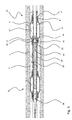
- FIG. 2 Another embodiment of the annular barrier 1 is shown in Fig. 2 .
- the fastening means 8 in which the sleeve 6 is fastened is slidably connected to the connection part 9 (illustrated by the arrows).
- the connection part 9 illustrated by the arrows.
- the sleeve 6 When the expandable sleeve 6 is expanded in a transverse direction, the sleeve will tend to shorten in its longitudinal direction - if possible.
- the sleeve 6 is allowed to reduce its longitudinal extension, resulting in a possibly larger expansion since the sleeve is not stretched as much as when the sleeve is fixedly connected to the connection part 9.
- sealing elements 14 are arranged between the sliding fastening means 8 and the connection part 9.
- the annular barrier 1 has one valve 13 arranged in the connection part 9 of the annular barrier in the transition between the cavity 12 and the annulus 3.
- the connection part 9 of the sliding connection may also be provided with a valve 13.
- the passages 11, 21 may have to be elongated in order to compensate for length necessitated by the sliding ability of the connection.
- An annular barrier 1 with a slidable connection between the sleeve 6 and the connection part 9 results in an increase of the expansion ability of the sleeve of up to 100% in relation to an annular barrier without any slidable connections.
- the annular barrier 1 has two slidable connections, increasing the expansion ability of the sleeve 6 even more.
- the annular barrier 1 of the invention has a valve 13 which is slidable between a position where the first passage 11 from the inside of the well tubular structure 3 and the cavity 12 is open and the second passage 21 from the inside of the well tubular structure and the annulus 2 is closed to a second position where the first passage is closed and the second is open.
- the valve 13 also has a third position in which both passages 11, 21 are closed.
- the expandable sleeve 6 is in its expanded condition and the unexpanded condition of the expandable sleeve is illustrated by a dotted line.
- the expandable sleeve 6 follows the surface of the tubular part 5 so that only a narrow space 12 is created between the two.
- the tubular part 5 thus does not have any indentation, and the cavity 12 is created solely by expansion of the sleeve 6.
- the annular barrier 1 may also have a valve 13 placed in the part between the two connection parts 9.
- a valve may be a one-way valve or a two-way valve.
- valve 13 of the annular barrier 1 may be a three-way valve which in a first position lets fluid into the space 12 between the expandable sleeve 6 and the tubular part 5, in a second position lets fluid into the annulus 2 between the well tubular structure 3 and the borehole, and in a third position stops the fluid from flowing.
- the expandable sleeve 6 of the annular barrier 1 has a length extending along the longitudinal extension of the well tubular structure 3.
- the expandable sleeve 6 has a wall thickness which is thinner than its length.
- the expandable sleeve 6 has a thickness of less than 25% of its length, preferably less than 15% of its length, more preferably less than 10% of its length.
- the diameter of the sleeve 6 of the annular barrier 1 is expanded from its initial unexpanded diameter to a larger diameter.
- the expandable sleeve 6 is capable of expanding to a diameter which is at least 10% larger than its initial diameter, preferably at least 15% larger, more preferably at least 30% larger.
- the fastening means 8 may have a projecting edge part which projects outwards from the connecting part 9.
- the projection edge part may also be in the form of tongues 32, as shown in Fig. 9 or 10 . Having a part of the fastening means 8 bending outwards means that the fastening means does not have a sharp edge which may cause the sleeve 6 to crack close to the fastening means when expanded.
- the expandable sleeve 6 of the annular barrier 1 may be made of metal or polymers, such as an elastomeric material, silicone, or natural or syntactic rubber.
- the expandable sleeve 6 When expanding the expandable sleeve 6, the expandable sleeve often expands in an uneven way, and it is therefore manufactured having a varying wall thickness in order to compensate for the uneven expansion.
- the expandable sleeve 6 is often made of metal, and in order to improve the sealing ability of the expandable sleeve towards the inside wall of the borehole, the expandable sleeve may be provided with sealing rings 33, such as rings of polymers, rubber, silicone, or the like sealing material.
- the expandable sleeve 6 may comprise a mesh, as shown in Fig. 10 , to protect the sleeve from damage when being run into the well along with the well tubular structure 3.
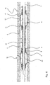
- a cross-sectional view of an annular barrier having a valve which is slidable so as to open and/or close the openings 11, 21.
- the sleeve of the annular barrier has two end parts welded on each end of a centre sleeve part.
- the two end parts have a surface inclining towards the centre part corresponding to an inclining surface on each end of the centre part. Due to the inclined surface, the welding area is increased, and due to a three part sleeve, the two ends may be made of a different material with higher ductility than the centre part, meaning that it stretches easily when the sleeve is expanded.
- the centre part of the expandable sleeve may be made of a material with a higher strength which is able to withstand a high hydraulic collapse pressure when the sleeve is expanded.
- the fastening means is a screw connection enabling the sleeve of the annular barrier to be screwed onto the connection part of the tubular part.
- the tubular part shown in Figs. 12-15 has an increased wall thickness in the connection part of the tubular part opposite the ends of the sleeve.
- the outer diameter is increased correspondingly.
- the surface can be machined to make the surface smoother and to make the outer diameter more exact without decreasing the resulting outer diameter of the tubular part.
- the sleeve is fastened in one end of the connection part of the tubular part, and in the other end, the sleeve is slidably connected to the other connection part of the tubular part.
- a sealing means is arranged so as to make a sealing connection between the sleeve and the connection parts.
- the fastening means is a welding seam since the sleeve is welded to the connection part of the tubular part forming part of the tubular structure.
- connection part projecting from the tubular part increasing the thickness of the tubular structure may be a layer welded onto the connection part or by other means applied as a layer onto the connection part, for instance sprayed onto the surface.
- connection is initially moulded with increased thickness.
- the layer applied onto the connection part may be made of a different material which is easier to machine into a precise diameter and a smoother surface than the material normally used for making tubular structures.
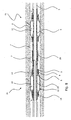
- annular barrier system 100 comprising the above-mentioned annular barrier 1.
- annular barrier system 100 is shown in Fig. 5 , where the annular barrier system comprises a tool 20 for expanding the expandable sleeve 6 of the annular barrier 1.
- the tool 20 expands the expandable sleeve 6 by applying a pressurised fluid through a passage 11 in the tubular part 5 into the space 12 between the expandable sleeve and the tubular part.
- the tool 20 comprises an isolation device 18 for isolating a first section 24 outside the passage 11, 21 between an outside wall 30 of the tool and the inside wall 16 of the well tubular structure.
- the pressurised fluid is created by increasing the pressure of the fluid in the isolation device 18.
- the tool 20 comprises at least one sealing means 25 for sealing against the inside wall of the well tubular structure 3 on each side of the valve 13 in order to isolate the first section 24 inside the well tubular structure.
- the sealing means 25 is shown as two separate sealing means, but may as well be just one means which is expandable in two positions.
- the sealing means 25 may be made of an expandable polymer which is inflated by the well fluid or a gas comprised in a reservoir in the tool 20. When the isolation device 18 is no longer needed, the sealing means 25 is deflated and the tool 20 may be retracted.
- this tool 20 can be used for injecting cement into the cavity in known annular barriers in order to expand the expandable sleeves of known annular barriers. In this case, no valve is needed due to the fact that the cement hardens, and the cavity thus does not have to be closed in order to keep the cement inside the cavity.
- the pressurised fluid is well fluid, i.e. the fluid present in the well tubular structure 3, and the tool 20 has a suction means for suction of fluid into the tool and out into the isolated section 24 or directly into the passage 11, 21.
- the passage 11 When the tool 20 has expanded the expandable sleeve 6 by pressing fluid into the space or cavity 12 between the expandable sleeve and the tubular part 5 of the annular barrier 1, the passage 11 has to be closed in order to stop the fluid from running back into the well tubular structure 3 when the tool is retracted.
- the passage 11 is controlled by means of a valve 13.
- the tool 20 has means for adjusting the valve from one position to another position, e.g. from an open position to a closed position.
- the means for adjusting the valve 13 is a key engaging indentations 34 in the valve in order to move the valve.
- Fig. 5 the tool 20 is shown having a stroker tool 27 for letting pressurised fluid into the first section.
- the annular barrier system 100 of Fig. 5 comprises two annular barriers 1 positioned at a distance from each other along a production zone 29 in the well tubular structure 3.
- One annular barrier 1, 31 has already been inflated, e.g. in order to centralise the well tubular structure 3 in the borehole or in a previous run to isolate the production zone together with the second annular barrier 1, 41.
- the valves 13 of the first annular barrier 31 are closed (illustrated by circles with a cross).
- the system 100 comprises a plurality of annular barriers 1 fluidly connected by means of a fluid connection, such as a tube running on the outside of the well tubular structure 3 so that, by expanding one annular barrier, a plurality of annular barriers can be expanded in turn.
- a fluid connection such as a tube running on the outside of the well tubular structure 3 so that, by expanding one annular barrier, a plurality of annular barriers can be expanded in turn.
- the tool 20 can expand all the subsequent barriers 1 by injecting a pressurised fluid into the first annular barrier.
- the tool 20 only has to be lowered into the top part of the well and not all the way into the well.
- the well tubular structure 3 When producing, the well tubular structure 3 is often perforated to allow the oil fluid to flow into the well tubular structure and further on to the surface of the well.
- the annular barriers 1 cannot be expanded by building up a pressure within the well tubular structure 3, such as by means of coiled tubing.
- annular barriers arranged below the perforations can be expanded without sealing off a zone around each annular barrier.
- the first annular barrier When linking annular barriers 1 together via a fluid communication as mentioned, the first annular barrier is expanded in order to expand also the subsequent barriers.
- the first barrier 1 can be expanded by a tool 20 by means of the isolation device 18 or by temporarily plugging the well beneath the first barrier and applying a pressure of fluid from the surface.
- the tool 20 may comprise a downhole tractor, such as a Well Tractor®.
- the tool 20 may have several stroker tools 27 in order to expand several expandable tubular sleeves 6 at a time.
- the tool 20 may have more than one isolation device 18 and thus be able to operate several annular barriers 1 at the same time, e.g. expanding several sleeves 6 or measuring the conditions of a production zone 29, the annulus 2, and/or the inside pressure of the expanded annular barrier.
- the tool may also be a drill pipe assembly arranged as part of the drill pipe, e.g. in the end of a drill pipe.
- the tool is in the same way arranged opposite the sleeve and thereby isolates a zone by means of a sealing means 25.
- the drill pipe is closed in the bottom by letting a ball into the drill pipe, closing the bottom when landing in the known ball catcher. Subsequently, the drill pipe, and thereby the zone, are pressurised in order to expand the sleeve.
- the tool connected to the drill pipe may also be is inserted into the tubular structure, and packers are expanded between the inside wall of the tubular structure and the outside wall of the drill pipe.
- the tool further comprises means for closing the top of the tubular structure or of the well. Subsequently, the annular area between the drill pipe and the tubular structure is pressurised in order to expend the sleeve.
- the drill pipe may also be called an inner wash down string.
- the tool has means for closing a zone on the inside of the tubular structure.
- the means closes the tubular structure in the top of the well and in a position on the other side of the sleeve to be expanded. Then, the zone inside the tubular structure is pressurised in order to expand the sleeve.
- the tool 20 may have means for measuring the flow, temperature, pressure, density, water hold-up, and/or expansion of the sleeve 6.
- the conditions of the production zone 29 can be evaluated.
- the tool 20 has a recording and/or transmitting device for recording and/or transmitting data from measurements performed by the tool.
- the pressure on one side of an expanded annular barrier 1 is larger than the pressure within the cavity 12 of the annular barrier.
- the fluid from the high-pressure zone HP may thus try to undermine the connection between the expandable sleeve 6 and the inside wall of the borehole in order to equalise the pressure difference.
- the tool 30 opens the valve 13 of the annular barrier 1, allowing fluid to flow from the high-pressure zone into the annular barrier as shown in Fig. 7 . In this way, it is ensured that the fluid from a high-pressure zone does not break the seal between the expanded annular barrier 1 and the inside wall of the borehole.
- the tool 20 of Fig. 6 uses coiled tubing for expanding the expandable sleeve 6 of two annular barriers 1 at the same time.
- a tool 20 with coiled tubing can pressurise the fluid in the well tubular structure 3 without having to isolate a section 24 of the well tubular structure; however, the tool may need to plug the well tubular structure further down the borehole from the two annular barriers 1 to be operated.
- the annular barrier system 100 of the present invention may also expand the sleeve 6 by means of a drill pipe or a wireline tool, such as the one shown in Fig. 5 .
- the annular barrier system 100 may comprise an anchor tool 26 for anchoring of the tool 20 inside the well tubular structure 3 when operating the annular barriers 1, as shown in Fig. 5 .
- the tool 20 comprises a reservoir containing the pressurised fluid, e.g. when the fluid used for expanding the sleeve 6 is cement, gas, or a two-component compound.
- annular barriers 1 are inflated simultaneously into having a pressure higher than that of the annulus 2.
- the flow of the pressurised fluid is illustrated by arrows.
- the annular barriers 1 during production are shown in Fig. 7 where the valves 13 of the annular barriers have been closed and the production valve 35 is in fluid communication with the production screen and thus the production zone 29 of the formation.
- the valves 13 controlling the passage from the non-production zone of the annulus 2 and the cavity 12 are opened so that the pressure of well fluid in the cavity is the same as the pressure of well fluid in the non-production zone.
- the arrow inside the well tubular structure 3 illustrates the flow of oil. This ensures that the highest pressure in relation to the formation pressure is maintained within the cavity 12, thereby reducing the differential pressure across the expandable sleeve 6.
- the annular barriers 1 of the present invention may also be used when fracturing the formation in order to enable oil to run out of the formation at a higher rate.
- An annular barrier 1 is expanded on each side of the future production zone 29. Pressurised well fluid or water is injected through the production valve 35 and thus through the production screen 29 in order to crack and penetrate the formation. While fracturing, one of the valves 13 in each annular barrier 1 is adjusted so that the pressurised fluid in the fracturing zone also flows into the cavity 12 of the annular barriers 1, reducing the risk of the fluid undermining the seal between the sleeve 6 and the inside wall of the borehole, and also reducing the risk of the expandable sleeve collapsing inwards. The other valve 13 in each annular barrier 1 is kept closed.
- An annular barrier 1 may also be called a packer or the like expandable means.
- the well tubular structure 3 can be the production tubing or casing or a similar kind of tubing downhole in a well or a borehole.
- the annular barrier 1 can be used both in between the inner production tubing and an outer tubing in the borehole or between a tubing and the inner wall of the borehole.
- a well may have several kinds of tubing and the annular barrier 1 of the present invention can be mounted for use in all of them.
- the valve 13 may be any kind of valve capable of controlling flow, such as a ball valve, butterfly valve, choke valve, check valve or non-return valve, diaphragm valve, expansion valve, gate valve, globe valve, knife valve, needle valve, piston valve, pinch valve, or plug valve.
- a ball valve such as a ball valve, butterfly valve, choke valve, check valve or non-return valve, diaphragm valve, expansion valve, gate valve, globe valve, knife valve, needle valve, piston valve, pinch valve, or plug valve.
- the expandable tubular metal sleeve 6 may be a cold-drawn or hot-drawn tubular structure.
- the fluid used for expanding the expandable sleeve 6 may be any kind of well fluid present in the borehole surrounding the tool 20 and/or the well tubular structure 3.
- the fluid may be cement, gas, water, polymers, or a two-component compound, such as powder or particles mixing or reacting with a binding or hardening agent.
- the means for measuring the flow, temperature, pressure, density, water hold-up, and/or expansion of the sleeve 6 may be any kind of sensors.
- the sensor for measuring the expansion of the sleeve 6 may be e.g. a strain gauge.
- the recording device may have a memory.
- the transmitting device may transmit data by means of wireless communication, fibre optic, wireline, or fluid telemetry.
Claims (13)
- Système de barrière annulaire (100) pour agrandir une barrière annulaire (1) dans un anneau (2) entre une structure tubulaire de puits (3) et une paroi intérieure (4) d'un trou de forage en fond de puits, comprenant:- une barrière annulaire (1) comprenant une partie tubulaire (5) destinée à être montée comme une partie de la structure tubulaire de puits, la barrière annulaire comprenant en outre un manchon extensible (6) entourant la partie tubulaire, au moins une extrémité (7) du manchon extensible étant fixée au moyen d'un moyen de fixation (8) de ou à une partie de connexion (9) dans la partie tubulaire, et- un outil (20) pour agrandir le manchon extensible en laissant un fluide sous pression passer à travers un passage (11, 21) dans la partie tubulaire dans un espace (12) entre le manchon extensible et la partie tubulaire,
caractérisé en ce que l'outil a un moyen de fourniture de pression (27) pour prélever dans le fluide depuis le trou de forage et pour fournir le fluide sous pression. - Système de barrière annulaire selon la revendication 1 où la barrière annulaire a une soupape (13) pour commander le passage de fluide sous pression dans l'espace entre le manchon extensible et la partie tubulaire.
- Système de barrière annulaire selon l'une quelconque des revendications précédentes où le manchon a deux extrémités faites d'un matériau différent d'une partie centrale du manchon.
- Système de barrière annulaire selon la revendication 2 où la soupape est positionnée dans au moins l'une des parties de connexion.
- Système de barrière annulaire selon la revendication 2 ou 4, où la soupape est une soupape à trois voies pour, dans une première position, laisser entrer du fluide dans l'espace entre le manchon extensible et la partie tubulaire, dans une seconde position laisser entrer du fluide dans l'anneau entre la structure tubulaire de puits et le trou de forage, et dans une troisième position empêcher l'écoulement du fluide.
- Système de barrière annulaire selon la revendication 2, 4 ou 5 où la soupape dans une première position laisse entrer du fluide dans l'espace entre le manchon extensible et la partie tubulaire, dans une seconde position laisse entrer du fluide dans l'anneau entre la structure tubulaire de puits et le trou de forage, dans une troisième position empêche l'écoulement du fluide, et dans une quatrième position laisse du fluide s'écouler entre l'anneau et l'espace.
- Système de barrière annulaire selon l'une quelconque des revendications 1-6 où l'outil a des moyens pour ajuster la soupape d'une position dans une autre.
- Système de barrière annulaire selon l'une quelconque des revendications précédentes où l'outil a des garnitures pour fermer une zone annulaire.
- Système de barrière annulaire selon l'une quelconque des revendications précédentes où l'outil comporte un dispositif d'isolation (18) pour isoler une première section (24) entre une paroi extérieure de l'outil (30) et une paroi intérieure de la structure tubulaire de puits (11) à l'extérieur du passage de la partie tubulaire.
- Système de barrière annulaire selon la revendication 9 où le dispositif d'isolation de l'outil comporte au moins des moyens d'étanchéisation (25) pour l'étanchéité contre la paroi intérieure de la structure tubulaire de puits sur chaque côté de la soupape afin d'isoler la première section à l'intérieur de la structure tubulaire de puits.
- Système de barrière annulaire selon l'une quelconque des revendications précédentes où l'outil comporte des moyens pour la connexion à une tige de sondage.
- Procédé d'extension pour agrandir une barrière annulaire selon la revendication 9 ou 10 à l'intérieur d'un trou de forage comprenant un fluide de puits ayant une certaine pression, le procédé comprenant les étapes de :placer un outil à l'extérieur du passage de la partie tubulaire de la barrière annulaire,isoler le passage au moyen du dispositif d'isolation de l'outil, etaugmenter la pression du fluide de puits à l'intérieur du dispositif d'isolation afin d'agrandir le manchon de la barrière annulaire,ou les étapes de :placer un outil à l'extérieur du passage de la partie tubulaire de la barrière annulaire, etouvrir la soupape dans la partie de connexion de la barrière annulaire de telle manière que le fluide sous pression dans un tubage spiralé, dans une chambre dans l'outil, ou dans une section isolée entre une paroi extérieure de l'outil et une paroi intérieure de la structure tubulaire de puits est laissé entrer dans l'espace entre la partie tubulaire et le manchon extensible de la barrière annulaire afin d'agrandir le manchon.
- Procédé de production pour produire du pétrole ou un fluide analogue à travers une structure tubulaire de puits comportant une zone de production (29) dans lequel la structure tubulaire de puits comporte des perforations, un écran, ou autre et au moins deux barrières annulaires selon les revendications 1-11, comprenant les étapes de :agrandir une première barrière annulaire (31) d'un côté de la zone de production de la structure tubulaire de puits,agrandir une seconde barrière annulaire (41) d'un autre côté de la zone de production de la structure tubulaire de puits, etlaisser du fluide entrer dans la structure tubulaire de puits à travers la zone de production.
Priority Applications (1)
| Application Number | Priority Date | Filing Date | Title |
|---|---|---|---|
| EP10700124.0A EP2391796B1 (fr) | 2009-01-12 | 2010-01-12 | Barrière annulaire et système à barrière annulaire |
Applications Claiming Priority (3)
| Application Number | Priority Date | Filing Date | Title |
|---|---|---|---|
| EP20090150385 EP2206879B1 (fr) | 2009-01-12 | 2009-01-12 | Barrière annulaire et système à barrière annulaire |
| EP10700124.0A EP2391796B1 (fr) | 2009-01-12 | 2010-01-12 | Barrière annulaire et système à barrière annulaire |
| PCT/EP2010/050298 WO2010079237A1 (fr) | 2009-01-12 | 2010-01-12 | Barrière annulaire et système de barrière annulaire |
Publications (2)
| Publication Number | Publication Date |
|---|---|
| EP2391796A1 EP2391796A1 (fr) | 2011-12-07 |
| EP2391796B1 true EP2391796B1 (fr) | 2015-02-25 |
Family
ID=40765793
Family Applications (2)
| Application Number | Title | Priority Date | Filing Date |
|---|---|---|---|
| EP20090150385 Revoked EP2206879B1 (fr) | 2009-01-12 | 2009-01-12 | Barrière annulaire et système à barrière annulaire |
| EP10700124.0A Not-in-force EP2391796B1 (fr) | 2009-01-12 | 2010-01-12 | Barrière annulaire et système à barrière annulaire |
Family Applications Before (1)
| Application Number | Title | Priority Date | Filing Date |
|---|---|---|---|
| EP20090150385 Revoked EP2206879B1 (fr) | 2009-01-12 | 2009-01-12 | Barrière annulaire et système à barrière annulaire |
Country Status (10)
| Country | Link |
|---|---|
| US (3) | US9080415B2 (fr) |
| EP (2) | EP2206879B1 (fr) |
| CN (2) | CN104100225B (fr) |
| AU (1) | AU2010204282B2 (fr) |
| BR (2) | BR122014014688B1 (fr) |
| CA (2) | CA2746015C (fr) |
| DK (2) | DK178851B1 (fr) |
| ES (1) | ES2464457T3 (fr) |
| MX (1) | MX2011006115A (fr) |
| WO (1) | WO2010079237A1 (fr) |
Families Citing this family (82)
| Publication number | Priority date | Publication date | Assignee | Title |
|---|---|---|---|---|
| EP2206879B1 (fr) | 2009-01-12 | 2014-02-26 | Welltec A/S | Barrière annulaire et système à barrière annulaire |
| GB0909086D0 (en) * | 2009-05-27 | 2009-07-01 | Read Well Services Ltd | An active external casing packer (ecp) for frac operations in oil and gas wells |
| DK2436874T3 (da) * | 2010-09-30 | 2013-10-07 | Welltec As | Borerør |
| WO2012045355A1 (fr) * | 2010-10-07 | 2012-04-12 | Welltec A/S | Barrière annulaire |
| EP3216976A1 (fr) * | 2010-10-07 | 2017-09-13 | Welltec A/S | Barrière annulaire |
| US8770305B2 (en) | 2010-11-22 | 2014-07-08 | Boise State University | Modular hydraulic packer-and-port system |
| AU2013100365C4 (en) * | 2010-12-17 | 2015-11-26 | Welltec Oilfield Solutions Ag | Well completion |
| EP2466065B1 (fr) * | 2010-12-17 | 2013-05-15 | Welltec A/S | Exécution de puits |
| CN102155251A (zh) * | 2011-02-28 | 2011-08-17 | 河南理工大学 | 一种水力封孔器 |
| EP2538018A1 (fr) * | 2011-06-23 | 2012-12-26 | Welltec A/S | Barrière annulaire dotée d'un joint externe |
| EP2565368A1 (fr) * | 2011-08-31 | 2013-03-06 | Welltec A/S | Barrière annulaire dotée d'amplification de la pression |
| EP3106604A1 (fr) * | 2011-08-31 | 2016-12-21 | Welltec A/S | Système de fond de trou et procédé de fixation de boîtiers supérieurs et inférieurs par l'intermédiaire d'un manchon métallique expansible |
| DK2570587T3 (da) | 2011-09-13 | 2013-11-11 | Welltec As | Ringformet barriere med sikkerhedsmetalrørstykke |
| EP2599956A1 (fr) * | 2011-11-30 | 2013-06-05 | Welltec A/S | Système de barrière annulaire avec circuits d'écoulement |
| DK2607614T3 (en) * | 2011-12-21 | 2015-02-02 | Welltec As | Annular barrier with an expansion detection device |
| EP2607613A1 (fr) | 2011-12-21 | 2013-06-26 | Welltec A/S | Barrière annulaire avec dispositif à actionnement automatique |
| US9010416B2 (en) * | 2012-01-25 | 2015-04-21 | Baker Hughes Incorporated | Tubular anchoring system and a seat for use in the same |
| CA3076393C (fr) * | 2012-03-07 | 2023-03-28 | Halliburton Manufacturing And Services Limited | Appareil de fond de trou |
| FR2988126B1 (fr) | 2012-03-16 | 2015-03-13 | Saltel Ind | Dispositif d'isolation d'une partie d'un puits |
| CN104285029B (zh) * | 2012-03-21 | 2017-05-10 | 沙特阿拉伯石油公司 | 用于移动连续管柱的井下方法和可膨胀箍 |
| BR112015004319B1 (pt) * | 2012-08-28 | 2021-03-09 | Halliburton Energy Services, Inc | método para completar um poço, e, conexão de tubulação de furo de poço |
| FR2996247B1 (fr) * | 2012-10-03 | 2015-03-13 | Saltel Ind | Procede de fracturation hydraulique et materiel correspondant |
| US20140262290A1 (en) * | 2013-03-14 | 2014-09-18 | Baker Hughes Incorpoarated | Method and system for treating a borehole |
| EP2789791A1 (fr) * | 2013-04-12 | 2014-10-15 | Welltec A/S | Élément tubulaire extensible de fond de trou |
| EP2789792A1 (fr) | 2013-04-12 | 2014-10-15 | Welltec A/S | Élément tubulaire extensible de fond de trou |
| GB2517202B (en) | 2013-08-16 | 2020-03-18 | Morphpackers Ltd | Improved filling mechanism for a morphable sleeve |
| EP2876251A1 (fr) * | 2013-11-21 | 2015-05-27 | Welltec A/S | Barrière annulaire avec compensation de pression passive |
| EP2878763A1 (fr) * | 2013-11-29 | 2015-06-03 | Welltec A/S | Colonne de tubage de fond de trou |
| FR3016389B1 (fr) | 2014-01-10 | 2016-01-08 | Saltel Ind | Dispositif d'isolation pour puits |
| USRE49437E1 (en) | 2014-09-30 | 2023-02-28 | Apple Inc. | Audio driver and power supply unit architecture |
| KR101973488B1 (ko) | 2014-09-30 | 2019-04-29 | 애플 인크. | 표면 반사에 의해 야기되는 오디오 칼라레이션이 감소된 라우드스피커 |
| GB201417671D0 (en) * | 2014-10-07 | 2014-11-19 | Meta Downhole Ltd | Improved isolation barrier |
| EP3073050A1 (fr) * | 2015-03-27 | 2016-09-28 | Welltec A/S | Une structure tubulaire de fond |
| US10156119B2 (en) | 2015-07-24 | 2018-12-18 | Innovex Downhole Solutions, Inc. | Downhole tool with an expandable sleeve |
| US10408012B2 (en) | 2015-07-24 | 2019-09-10 | Innovex Downhole Solutions, Inc. | Downhole tool with an expandable sleeve |
| EP3159478A1 (fr) * | 2015-10-23 | 2017-04-26 | Welltec A/S | Étanchéification d'un système d'achèvement de fond de trou par rapport à la couche de couverture |
| AU2016310072B2 (en) * | 2015-08-17 | 2019-08-08 | Welltec Oilfield Solutions Ag | Downhole completion system sealing against the cap layer |
| JP6620286B2 (ja) * | 2015-12-15 | 2019-12-18 | 帝石削井工業株式会社 | パッカー |
| CN108474242A (zh) * | 2016-01-26 | 2018-08-31 | 韦尔泰克有限公司 | 用于低压区域的环状屏障和井下系统 |
| EP3255240A1 (fr) * | 2016-06-10 | 2017-12-13 | Welltec A/S | Système de chevauchement de fond de trou |
| US10834497B2 (en) | 2016-09-23 | 2020-11-10 | Apple Inc. | User interface cooling using audio component |
| US10631071B2 (en) | 2016-09-23 | 2020-04-21 | Apple Inc. | Cantilevered foot for electronic device |
| DK3526440T3 (da) | 2016-10-12 | 2024-02-12 | Welltec Oilfield Solutions Ag | Ekspansionssamling |
| EP3327246A1 (fr) * | 2016-11-25 | 2018-05-30 | Welltec A/S | Barrière annulaire avec vérification d'expansion |
| US10227842B2 (en) | 2016-12-14 | 2019-03-12 | Innovex Downhole Solutions, Inc. | Friction-lock frac plug |
| US10316619B2 (en) | 2017-03-16 | 2019-06-11 | Saudi Arabian Oil Company | Systems and methods for stage cementing |
| DK3601718T3 (en) * | 2017-03-27 | 2021-09-20 | Saltel Ind | Expandable metal packer system and methodology with annulus pressure compensation |
| US10544648B2 (en) | 2017-04-12 | 2020-01-28 | Saudi Arabian Oil Company | Systems and methods for sealing a wellbore |
| US10557330B2 (en) | 2017-04-24 | 2020-02-11 | Saudi Arabian Oil Company | Interchangeable wellbore cleaning modules |
| EP3480421A1 (fr) * | 2017-11-06 | 2019-05-08 | Welltec Oilfield Solutions AG | Barrière annulaire de puits de faible diamètre |
| CN110892133A (zh) * | 2017-07-27 | 2020-03-17 | 韦尔泰克油田解决方案股份公司 | 用于小直径井的环状屏障 |
| US10487604B2 (en) | 2017-08-02 | 2019-11-26 | Saudi Arabian Oil Company | Vibration-induced installation of wellbore casing |
| US10378298B2 (en) | 2017-08-02 | 2019-08-13 | Saudi Arabian Oil Company | Vibration-induced installation of wellbore casing |
| US10597962B2 (en) | 2017-09-28 | 2020-03-24 | Saudi Arabian Oil Company | Drilling with a whipstock system |
| US10378339B2 (en) | 2017-11-08 | 2019-08-13 | Saudi Arabian Oil Company | Method and apparatus for controlling wellbore operations |
| EP3495602A1 (fr) * | 2017-12-07 | 2019-06-12 | Welltec Oilfield Solutions AG | Système de réparation de fond de trou |
| CN107916908A (zh) * | 2017-12-11 | 2018-04-17 | 中国石油天然气股份有限公司 | 一种管内复合密封机构 |
| CN110273652B (zh) * | 2018-03-14 | 2021-06-01 | 中国石油天然气股份有限公司 | 采油井酸洗管柱结构及采油井的酸洗方法 |
| US10689914B2 (en) | 2018-03-21 | 2020-06-23 | Saudi Arabian Oil Company | Opening a wellbore with a smart hole-opener |
| US10689913B2 (en) | 2018-03-21 | 2020-06-23 | Saudi Arabian Oil Company | Supporting a string within a wellbore with a smart stabilizer |
| GB2572449B (en) * | 2018-03-30 | 2020-09-16 | Morphpackers Ltd | Improved isolation barrier |
| US10794170B2 (en) | 2018-04-24 | 2020-10-06 | Saudi Arabian Oil Company | Smart system for selection of wellbore drilling fluid loss circulation material |
| US10612362B2 (en) | 2018-05-18 | 2020-04-07 | Saudi Arabian Oil Company | Coiled tubing multifunctional quad-axial visual monitoring and recording |
| CN109138933B (zh) * | 2018-07-27 | 2020-11-06 | 中国石油天然气股份有限公司 | 弹性筛管及防砂管柱 |
| US10989016B2 (en) | 2018-08-30 | 2021-04-27 | Innovex Downhole Solutions, Inc. | Downhole tool with an expandable sleeve, grit material, and button inserts |
| CN109138880B (zh) * | 2018-10-27 | 2023-10-20 | 长葛市金博机械化工有限公司 | 双向锚定器 |
| US11125039B2 (en) | 2018-11-09 | 2021-09-21 | Innovex Downhole Solutions, Inc. | Deformable downhole tool with dissolvable element and brittle protective layer |
| WO2020152260A1 (fr) * | 2019-01-23 | 2020-07-30 | Saltel Industries | Packer métallique extensible avec système d'ancrage |
| US11788365B2 (en) | 2019-01-23 | 2023-10-17 | Saltel Industries Sas | Expandable metal packer system with pressure control device |
| US11396787B2 (en) | 2019-02-11 | 2022-07-26 | Innovex Downhole Solutions, Inc. | Downhole tool with ball-in-place setting assembly and asymmetric sleeve |
| US11261683B2 (en) | 2019-03-01 | 2022-03-01 | Innovex Downhole Solutions, Inc. | Downhole tool with sleeve and slip |
| US11203913B2 (en) | 2019-03-15 | 2021-12-21 | Innovex Downhole Solutions, Inc. | Downhole tool and methods |
| WO2021010988A1 (fr) | 2019-07-16 | 2021-01-21 | Halliburton Energy Services, Inc. | Élément en caoutchouc gonflable qui crée également une garniture d'étanchéité de coupelle |
| US11572753B2 (en) | 2020-02-18 | 2023-02-07 | Innovex Downhole Solutions, Inc. | Downhole tool with an acid pill |
| US11299968B2 (en) | 2020-04-06 | 2022-04-12 | Saudi Arabian Oil Company | Reducing wellbore annular pressure with a release system |
| US11396789B2 (en) | 2020-07-28 | 2022-07-26 | Saudi Arabian Oil Company | Isolating a wellbore with a wellbore isolation system |
| US11414942B2 (en) | 2020-10-14 | 2022-08-16 | Saudi Arabian Oil Company | Packer installation systems and related methods |
| EP3992420A1 (fr) * | 2020-10-30 | 2022-05-04 | Welltec Oilfield Solutions AG | Ensemble de garniture d'étanchéité de fond de puits |
| CN112665473A (zh) * | 2020-12-10 | 2021-04-16 | 中煤科工开采研究院有限公司 | 一种爆破封孔方法 |
| US11624265B1 (en) | 2021-11-12 | 2023-04-11 | Saudi Arabian Oil Company | Cutting pipes in wellbores using downhole autonomous jet cutting tools |
| WO2023209442A1 (fr) | 2022-04-26 | 2023-11-02 | Downhole Products Limited | Collier d'arrêt d'affaissement comportant un joint pour empêcher une fuite de micro-espace annulaire |
| CN114934756B (zh) * | 2022-06-28 | 2024-01-05 | 中核通辽铀业有限责任公司 | 一种井内封堵结构、分层抽液量测量装置及其测量方法 |
Citations (2)
| Publication number | Priority date | Publication date | Assignee | Title |
|---|---|---|---|---|
| GB2398312A (en) * | 2003-02-13 | 2004-08-18 | Read Well Services Ltd | Downhole tubular sealing apparatus |
| US7306033B2 (en) * | 2004-08-04 | 2007-12-11 | Read Well Services Limited | Apparatus for isolating zones in a well |
Family Cites Families (21)
| Publication number | Priority date | Publication date | Assignee | Title |
|---|---|---|---|---|
| US4230180A (en) * | 1978-11-13 | 1980-10-28 | Westbay Instruments Ltd. | Isolating packer units in geological and geophysical measuring casings |
| US4260164A (en) | 1979-06-15 | 1981-04-07 | Halliburton Company | Inflatable packer assembly with control valve |
| US4349204A (en) * | 1981-04-29 | 1982-09-14 | Lynes, Inc. | Non-extruding inflatable packer assembly |
| US4499947A (en) * | 1983-12-12 | 1985-02-19 | Magyar Szenhidrogenipari Kutatofejleszto Intezet | Packer for separation of zones in a well bore |
| US4714117A (en) | 1987-04-20 | 1987-12-22 | Atlantic Richfield Company | Drainhole well completion |
| US5109925A (en) | 1991-01-17 | 1992-05-05 | Halliburton Company | Multiple stage inflation packer with secondary opening rupture disc |
| US5271469A (en) | 1992-04-08 | 1993-12-21 | Ctc International | Borehole stressed packer inflation system |
| CA2169382C (fr) | 1996-02-13 | 2003-08-05 | Marvin L. Holbert | Methode et appareil pour le gonflage de packer dans un puits de forage |
| US5711372A (en) | 1996-05-21 | 1998-01-27 | Tam International | Inflatable packer with port collar valving and method of setting |
| US6253857B1 (en) * | 1998-11-02 | 2001-07-03 | Halliburton Energy Services, Inc. | Downhole hydraulic power source |
| FR2791732B1 (fr) | 1999-03-29 | 2001-08-10 | Cooperation Miniere Et Ind Soc | Dispositif d'obturation d'un puits de forage |
| US6325144B1 (en) | 2000-06-09 | 2001-12-04 | Baker Hughes, Inc. | Inflatable packer with feed-thru conduits |
| US6854522B2 (en) * | 2002-09-23 | 2005-02-15 | Halliburton Energy Services, Inc. | Annular isolators for expandable tubulars in wellbores |
| US7347274B2 (en) * | 2004-01-27 | 2008-03-25 | Schlumberger Technology Corporation | Annular barrier tool |
| CN2707948Y (zh) * | 2004-06-10 | 2005-07-06 | 潘昌德 | 液压气动封隔器 |
| US20060042801A1 (en) | 2004-08-24 | 2006-03-02 | Hackworth Matthew R | Isolation device and method |
| US7284619B2 (en) | 2005-02-02 | 2007-10-23 | Tam International, Inc. | Packer with positionable collar |
| CN2779052Y (zh) * | 2005-04-14 | 2006-05-10 | 赵志诚 | 自动座封解封可验封式水井封隔器 |
| US7591321B2 (en) * | 2005-04-25 | 2009-09-22 | Schlumberger Technology Corporation | Zonal isolation tools and methods of use |
| US7757769B2 (en) * | 2007-10-04 | 2010-07-20 | Baker Hughes Incorporated | Wellbore and reservoir treatment device and method |
| EP2206879B1 (fr) | 2009-01-12 | 2014-02-26 | Welltec A/S | Barrière annulaire et système à barrière annulaire |
-
2009
- 2009-01-12 EP EP20090150385 patent/EP2206879B1/fr not_active Revoked
- 2009-01-12 ES ES09150385T patent/ES2464457T3/es active Active
-
2010
- 2010-01-12 CA CA2746015A patent/CA2746015C/fr not_active Expired - Fee Related
- 2010-01-12 CA CA2853370A patent/CA2853370C/fr not_active Expired - Fee Related
- 2010-01-12 BR BR122014014688-4A patent/BR122014014688B1/pt not_active IP Right Cessation
- 2010-01-12 US US13/138,139 patent/US9080415B2/en active Active
- 2010-01-12 CN CN201410244850.6A patent/CN104100225B/zh not_active Expired - Fee Related
- 2010-01-12 CN CN201080004299.8A patent/CN102272413B/zh not_active Expired - Fee Related
- 2010-01-12 WO PCT/EP2010/050298 patent/WO2010079237A1/fr active Application Filing
- 2010-01-12 AU AU2010204282A patent/AU2010204282B2/en not_active Ceased
- 2010-01-12 MX MX2011006115A patent/MX2011006115A/es active IP Right Grant
- 2010-01-12 EP EP10700124.0A patent/EP2391796B1/fr not_active Not-in-force
- 2010-01-12 BR BRPI1006151-7A patent/BRPI1006151B1/pt not_active IP Right Cessation
- 2010-09-13 DK DKPA201070395A patent/DK178851B1/en not_active IP Right Cessation
-
2014
- 2014-06-30 US US14/318,824 patent/US9745819B2/en active Active
-
2016
- 2016-12-09 DK DKPA201600758A patent/DK179865B1/en not_active IP Right Cessation
-
2017
- 2017-08-04 US US15/668,784 patent/US10202819B2/en active Active
Patent Citations (2)
| Publication number | Priority date | Publication date | Assignee | Title |
|---|---|---|---|---|
| GB2398312A (en) * | 2003-02-13 | 2004-08-18 | Read Well Services Ltd | Downhole tubular sealing apparatus |
| US7306033B2 (en) * | 2004-08-04 | 2007-12-11 | Read Well Services Limited | Apparatus for isolating zones in a well |
Also Published As
| Publication number | Publication date |
|---|---|
| EP2391796A1 (fr) | 2011-12-07 |
| US9080415B2 (en) | 2015-07-14 |
| DK178851B1 (en) | 2017-03-27 |
| EP2206879A1 (fr) | 2010-07-14 |
| CA2746015C (fr) | 2016-09-06 |
| US10202819B2 (en) | 2019-02-12 |
| US20140311751A1 (en) | 2014-10-23 |
| WO2010079237A1 (fr) | 2010-07-15 |
| BR122014014688B1 (pt) | 2021-01-12 |
| BRPI1006151A2 (pt) | 2016-02-23 |
| DK179865B1 (en) | 2019-08-05 |
| MX2011006115A (es) | 2011-06-24 |
| DK201070395A (en) | 2010-09-13 |
| BR122014014688A2 (pt) | 2016-03-22 |
| AU2010204282A1 (en) | 2011-06-23 |
| US20170328170A1 (en) | 2017-11-16 |
| CN104100225A (zh) | 2014-10-15 |
| DK201600758A1 (en) | 2017-02-13 |
| EP2206879B1 (fr) | 2014-02-26 |
| CA2853370A1 (fr) | 2010-07-15 |
| AU2010204282B2 (en) | 2013-07-04 |
| BRPI1006151B1 (pt) | 2020-11-17 |
| US20110266004A1 (en) | 2011-11-03 |
| ES2464457T3 (es) | 2014-06-02 |
| CN102272413B (zh) | 2014-07-02 |
| US9745819B2 (en) | 2017-08-29 |
| CN102272413A (zh) | 2011-12-07 |
| CA2853370C (fr) | 2017-06-20 |
| CN104100225B (zh) | 2017-03-29 |
| CA2746015A1 (fr) | 2010-07-15 |
Similar Documents
| Publication | Publication Date | Title |
|---|---|---|
| US10202819B2 (en) | Annular barrier and annular barrier system | |
| US8789581B2 (en) | Flow control devices on expandable tubing run through production tubing and into open hole | |
| US20080185144A1 (en) | Providing an expandable sealing element having a slot to receive a sensor array | |
| US20150034316A1 (en) | Annular barrier having expansion tubes | |
| CA2698712C (fr) | Equipement de chemisage geothermique avec packer | |
| EP1466072B1 (fr) | Element d'emballage gonflable |
Legal Events
| Date | Code | Title | Description |
|---|---|---|---|
| PUAI | Public reference made under article 153(3) epc to a published international application that has entered the european phase |
Free format text: ORIGINAL CODE: 0009012 |
|
| 17P | Request for examination filed |
Effective date: 20110811 |
|
| AK | Designated contracting states |
Kind code of ref document: A1 Designated state(s): AT BE BG CH CY CZ DE DK EE ES FI FR GB GR HR HU IE IS IT LI LT LU LV MC MK MT NL NO PL PT RO SE SI SK SM TR |
|
| DAX | Request for extension of the european patent (deleted) | ||
| 17Q | First examination report despatched |
Effective date: 20130523 |
|
| GRAP | Despatch of communication of intention to grant a patent |
Free format text: ORIGINAL CODE: EPIDOSNIGR1 |
|
| INTG | Intention to grant announced |
Effective date: 20140417 |
|
| GRAS | Grant fee paid |
Free format text: ORIGINAL CODE: EPIDOSNIGR3 |
|
| GRAP | Despatch of communication of intention to grant a patent |
Free format text: ORIGINAL CODE: EPIDOSNIGR1 |
|
| INTG | Intention to grant announced |
Effective date: 20140829 |
|
| GRAA | (expected) grant |
Free format text: ORIGINAL CODE: 0009210 |
|
| AK | Designated contracting states |
Kind code of ref document: B1 Designated state(s): AT BE BG CH CY CZ DE DK EE ES FI FR GB GR HR HU IE IS IT LI LT LU LV MC MK MT NL NO PL PT RO SE SI SK SM TR |
|
| REG | Reference to a national code |
Ref country code: GB Ref legal event code: FG4D |
|
| REG | Reference to a national code |
Ref country code: CH Ref legal event code: EP |
|
| REG | Reference to a national code |
Ref country code: IE Ref legal event code: FG4D |
|
| REG | Reference to a national code |
Ref country code: DE Ref legal event code: R096 Ref document number: 602010022484 Country of ref document: DE Effective date: 20150409 |
|
| REG | Reference to a national code |
Ref country code: AT Ref legal event code: REF Ref document number: 712167 Country of ref document: AT Kind code of ref document: T Effective date: 20150415 |
|
| REG | Reference to a national code |
Ref country code: NL Ref legal event code: T3 |
|
| REG | Reference to a national code |
Ref country code: AT Ref legal event code: MK05 Ref document number: 712167 Country of ref document: AT Kind code of ref document: T Effective date: 20150225 |
|
| REG | Reference to a national code |
Ref country code: NO Ref legal event code: T2 Effective date: 20150225 |
|
| REG | Reference to a national code |
Ref country code: LT Ref legal event code: MG4D |
|
| PG25 | Lapsed in a contracting state [announced via postgrant information from national office to epo] |
Ref country code: FI Free format text: LAPSE BECAUSE OF FAILURE TO SUBMIT A TRANSLATION OF THE DESCRIPTION OR TO PAY THE FEE WITHIN THE PRESCRIBED TIME-LIMIT Effective date: 20150225 Ref country code: SE Free format text: LAPSE BECAUSE OF FAILURE TO SUBMIT A TRANSLATION OF THE DESCRIPTION OR TO PAY THE FEE WITHIN THE PRESCRIBED TIME-LIMIT Effective date: 20150225 Ref country code: ES Free format text: LAPSE BECAUSE OF FAILURE TO SUBMIT A TRANSLATION OF THE DESCRIPTION OR TO PAY THE FEE WITHIN THE PRESCRIBED TIME-LIMIT Effective date: 20150225 Ref country code: HR Free format text: LAPSE BECAUSE OF FAILURE TO SUBMIT A TRANSLATION OF THE DESCRIPTION OR TO PAY THE FEE WITHIN THE PRESCRIBED TIME-LIMIT Effective date: 20150225 Ref country code: LT Free format text: LAPSE BECAUSE OF FAILURE TO SUBMIT A TRANSLATION OF THE DESCRIPTION OR TO PAY THE FEE WITHIN THE PRESCRIBED TIME-LIMIT Effective date: 20150225 |
|
| PG25 | Lapsed in a contracting state [announced via postgrant information from national office to epo] |
Ref country code: IS Free format text: LAPSE BECAUSE OF FAILURE TO SUBMIT A TRANSLATION OF THE DESCRIPTION OR TO PAY THE FEE WITHIN THE PRESCRIBED TIME-LIMIT Effective date: 20150625 Ref country code: AT Free format text: LAPSE BECAUSE OF FAILURE TO SUBMIT A TRANSLATION OF THE DESCRIPTION OR TO PAY THE FEE WITHIN THE PRESCRIBED TIME-LIMIT Effective date: 20150225 Ref country code: LV Free format text: LAPSE BECAUSE OF FAILURE TO SUBMIT A TRANSLATION OF THE DESCRIPTION OR TO PAY THE FEE WITHIN THE PRESCRIBED TIME-LIMIT Effective date: 20150225 Ref country code: GR Free format text: LAPSE BECAUSE OF FAILURE TO SUBMIT A TRANSLATION OF THE DESCRIPTION OR TO PAY THE FEE WITHIN THE PRESCRIBED TIME-LIMIT Effective date: 20150526 |
|
| PG25 | Lapsed in a contracting state [announced via postgrant information from national office to epo] |
Ref country code: EE Free format text: LAPSE BECAUSE OF FAILURE TO SUBMIT A TRANSLATION OF THE DESCRIPTION OR TO PAY THE FEE WITHIN THE PRESCRIBED TIME-LIMIT Effective date: 20150225 Ref country code: CZ Free format text: LAPSE BECAUSE OF FAILURE TO SUBMIT A TRANSLATION OF THE DESCRIPTION OR TO PAY THE FEE WITHIN THE PRESCRIBED TIME-LIMIT Effective date: 20150225 Ref country code: SK Free format text: LAPSE BECAUSE OF FAILURE TO SUBMIT A TRANSLATION OF THE DESCRIPTION OR TO PAY THE FEE WITHIN THE PRESCRIBED TIME-LIMIT Effective date: 20150225 Ref country code: RO Free format text: LAPSE BECAUSE OF FAILURE TO SUBMIT A TRANSLATION OF THE DESCRIPTION OR TO PAY THE FEE WITHIN THE PRESCRIBED TIME-LIMIT Effective date: 20150225 Ref country code: DK Free format text: LAPSE BECAUSE OF FAILURE TO SUBMIT A TRANSLATION OF THE DESCRIPTION OR TO PAY THE FEE WITHIN THE PRESCRIBED TIME-LIMIT Effective date: 20150225 |
|
| REG | Reference to a national code |
Ref country code: DE Ref legal event code: R097 Ref document number: 602010022484 Country of ref document: DE |
|
| PG25 | Lapsed in a contracting state [announced via postgrant information from national office to epo] |
Ref country code: PL Free format text: LAPSE BECAUSE OF FAILURE TO SUBMIT A TRANSLATION OF THE DESCRIPTION OR TO PAY THE FEE WITHIN THE PRESCRIBED TIME-LIMIT Effective date: 20150225 |
|
| PG25 | Lapsed in a contracting state [announced via postgrant information from national office to epo] |
Ref country code: IT Free format text: LAPSE BECAUSE OF FAILURE TO SUBMIT A TRANSLATION OF THE DESCRIPTION OR TO PAY THE FEE WITHIN THE PRESCRIBED TIME-LIMIT Effective date: 20150225 |
|
| PLBE | No opposition filed within time limit |
Free format text: ORIGINAL CODE: 0009261 |
|
| STAA | Information on the status of an ep patent application or granted ep patent |
Free format text: STATUS: NO OPPOSITION FILED WITHIN TIME LIMIT |
|
| REG | Reference to a national code |
Ref country code: FR Ref legal event code: PLFP Year of fee payment: 7 |
|
| 26N | No opposition filed |
Effective date: 20151126 |
|
| PG25 | Lapsed in a contracting state [announced via postgrant information from national office to epo] |
Ref country code: SI Free format text: LAPSE BECAUSE OF FAILURE TO SUBMIT A TRANSLATION OF THE DESCRIPTION OR TO PAY THE FEE WITHIN THE PRESCRIBED TIME-LIMIT Effective date: 20150225 |
|
| PG25 | Lapsed in a contracting state [announced via postgrant information from national office to epo] |
Ref country code: BE Free format text: LAPSE BECAUSE OF FAILURE TO SUBMIT A TRANSLATION OF THE DESCRIPTION OR TO PAY THE FEE WITHIN THE PRESCRIBED TIME-LIMIT Effective date: 20150225 |
|
| PG25 | Lapsed in a contracting state [announced via postgrant information from national office to epo] |
Ref country code: LU Free format text: LAPSE BECAUSE OF FAILURE TO SUBMIT A TRANSLATION OF THE DESCRIPTION OR TO PAY THE FEE WITHIN THE PRESCRIBED TIME-LIMIT Effective date: 20160112 |
|
| REG | Reference to a national code |
Ref country code: CH Ref legal event code: PL |
|
| PG25 | Lapsed in a contracting state [announced via postgrant information from national office to epo] |
Ref country code: MC Free format text: LAPSE BECAUSE OF FAILURE TO SUBMIT A TRANSLATION OF THE DESCRIPTION OR TO PAY THE FEE WITHIN THE PRESCRIBED TIME-LIMIT Effective date: 20150225 |
|
| PG25 | Lapsed in a contracting state [announced via postgrant information from national office to epo] |
Ref country code: CH Free format text: LAPSE BECAUSE OF NON-PAYMENT OF DUE FEES Effective date: 20160131 Ref country code: LI Free format text: LAPSE BECAUSE OF NON-PAYMENT OF DUE FEES Effective date: 20160131 |
|
| REG | Reference to a national code |
Ref country code: IE Ref legal event code: MM4A |
|
| REG | Reference to a national code |
Ref country code: FR Ref legal event code: PLFP Year of fee payment: 8 |
|
| PG25 | Lapsed in a contracting state [announced via postgrant information from national office to epo] |
Ref country code: IE Free format text: LAPSE BECAUSE OF NON-PAYMENT OF DUE FEES Effective date: 20160112 |
|
| PG25 | Lapsed in a contracting state [announced via postgrant information from national office to epo] |
Ref country code: MT Free format text: LAPSE BECAUSE OF FAILURE TO SUBMIT A TRANSLATION OF THE DESCRIPTION OR TO PAY THE FEE WITHIN THE PRESCRIBED TIME-LIMIT Effective date: 20150225 |
|
| REG | Reference to a national code |
Ref country code: NO Ref legal event code: CREP Representative=s name: ACAPO AS, POSTBOKS 1880 NORDNES, 5817 BERGEN, NORG |
|
| REG | Reference to a national code |
Ref country code: FR Ref legal event code: PLFP Year of fee payment: 9 |
|
| PG25 | Lapsed in a contracting state [announced via postgrant information from national office to epo] |
Ref country code: CY Free format text: LAPSE BECAUSE OF FAILURE TO SUBMIT A TRANSLATION OF THE DESCRIPTION OR TO PAY THE FEE WITHIN THE PRESCRIBED TIME-LIMIT Effective date: 20150225 Ref country code: HU Free format text: LAPSE BECAUSE OF FAILURE TO SUBMIT A TRANSLATION OF THE DESCRIPTION OR TO PAY THE FEE WITHIN THE PRESCRIBED TIME-LIMIT; INVALID AB INITIO Effective date: 20100112 Ref country code: SM Free format text: LAPSE BECAUSE OF FAILURE TO SUBMIT A TRANSLATION OF THE DESCRIPTION OR TO PAY THE FEE WITHIN THE PRESCRIBED TIME-LIMIT Effective date: 20150225 |
|
| PG25 | Lapsed in a contracting state [announced via postgrant information from national office to epo] |
Ref country code: PT Free format text: LAPSE BECAUSE OF FAILURE TO SUBMIT A TRANSLATION OF THE DESCRIPTION OR TO PAY THE FEE WITHIN THE PRESCRIBED TIME-LIMIT Effective date: 20150225 Ref country code: MK Free format text: LAPSE BECAUSE OF FAILURE TO SUBMIT A TRANSLATION OF THE DESCRIPTION OR TO PAY THE FEE WITHIN THE PRESCRIBED TIME-LIMIT Effective date: 20150225 Ref country code: TR Free format text: LAPSE BECAUSE OF FAILURE TO SUBMIT A TRANSLATION OF THE DESCRIPTION OR TO PAY THE FEE WITHIN THE PRESCRIBED TIME-LIMIT Effective date: 20150225 Ref country code: MT Free format text: LAPSE BECAUSE OF FAILURE TO SUBMIT A TRANSLATION OF THE DESCRIPTION OR TO PAY THE FEE WITHIN THE PRESCRIBED TIME-LIMIT Effective date: 20160131 |
|
| PG25 | Lapsed in a contracting state [announced via postgrant information from national office to epo] |
Ref country code: BG Free format text: LAPSE BECAUSE OF FAILURE TO SUBMIT A TRANSLATION OF THE DESCRIPTION OR TO PAY THE FEE WITHIN THE PRESCRIBED TIME-LIMIT Effective date: 20150225 |
|
| REG | Reference to a national code |
Ref country code: DE Ref legal event code: R082 Ref document number: 602010022484 Country of ref document: DE Representative=s name: SAMSON & PARTNER PATENTANWAELTE MBB, DE Ref country code: DE Ref legal event code: R081 Ref document number: 602010022484 Country of ref document: DE Owner name: WELLTEC OILFIELD SOLUTIONS AG, CH Free format text: FORMER OWNER: WELLTEC A/S, ALLEROED, DK |
|
| REG | Reference to a national code |
Ref country code: NO Ref legal event code: CHAD Owner name: WELLTEC OILFIELD SOLUTIONS AG, CH |
|
| REG | Reference to a national code |
Ref country code: GB Ref legal event code: 732E Free format text: REGISTERED BETWEEN 20190429 AND 20190502 |
|
| REG | Reference to a national code |
Ref country code: NL Ref legal event code: PD Owner name: WELLTEC OILFIELD SOLUTIONS AG; CH Free format text: DETAILS ASSIGNMENT: CHANGE OF OWNER(S), ASSIGNMENT; FORMER OWNER NAME: WELLTEC A/S Effective date: 20190607 |
|
| PGFP | Annual fee paid to national office [announced via postgrant information from national office to epo] |
Ref country code: NL Payment date: 20200120 Year of fee payment: 11 Ref country code: DE Payment date: 20200121 Year of fee payment: 11 |
|
| PGFP | Annual fee paid to national office [announced via postgrant information from national office to epo] |
Ref country code: FR Payment date: 20210118 Year of fee payment: 12 Ref country code: NO Payment date: 20210121 Year of fee payment: 12 |
|
| PGFP | Annual fee paid to national office [announced via postgrant information from national office to epo] |
Ref country code: GB Payment date: 20210120 Year of fee payment: 12 |
|
| REG | Reference to a national code |
Ref country code: DE Ref legal event code: R119 Ref document number: 602010022484 Country of ref document: DE |
|
| REG | Reference to a national code |
Ref country code: NL Ref legal event code: MM Effective date: 20210201 |
|
| PG25 | Lapsed in a contracting state [announced via postgrant information from national office to epo] |
Ref country code: NL Free format text: LAPSE BECAUSE OF NON-PAYMENT OF DUE FEES Effective date: 20210201 |
|
| PG25 | Lapsed in a contracting state [announced via postgrant information from national office to epo] |
Ref country code: DE Free format text: LAPSE BECAUSE OF NON-PAYMENT OF DUE FEES Effective date: 20210803 |
|
| REG | Reference to a national code |
Ref country code: NO Ref legal event code: MMEP |
|
| GBPC | Gb: european patent ceased through non-payment of renewal fee |
Effective date: 20220112 |
|
| PG25 | Lapsed in a contracting state [announced via postgrant information from national office to epo] |
Ref country code: NO Free format text: LAPSE BECAUSE OF NON-PAYMENT OF DUE FEES Effective date: 20220131 Ref country code: GB Free format text: LAPSE BECAUSE OF NON-PAYMENT OF DUE FEES Effective date: 20220112 |
|
| PG25 | Lapsed in a contracting state [announced via postgrant information from national office to epo] |
Ref country code: FR Free format text: LAPSE BECAUSE OF NON-PAYMENT OF DUE FEES Effective date: 20220131 |