EP2391414B1 - Insufflator - Google Patents
Insufflator Download PDFInfo
- Publication number
- EP2391414B1 EP2391414B1 EP10701387.2A EP10701387A EP2391414B1 EP 2391414 B1 EP2391414 B1 EP 2391414B1 EP 10701387 A EP10701387 A EP 10701387A EP 2391414 B1 EP2391414 B1 EP 2391414B1
- Authority
- EP
- European Patent Office
- Prior art keywords
- pressure
- insufflator
- flow
- flow channel
- circuit board
- Prior art date
- Legal status (The legal status is an assumption and is not a legal conclusion. Google has not performed a legal analysis and makes no representation as to the accuracy of the status listed.)
- Active
Links
Images

Classifications
-
- A—HUMAN NECESSITIES
- A61—MEDICAL OR VETERINARY SCIENCE; HYGIENE
- A61M—DEVICES FOR INTRODUCING MEDIA INTO, OR ONTO, THE BODY; DEVICES FOR TRANSDUCING BODY MEDIA OR FOR TAKING MEDIA FROM THE BODY; DEVICES FOR PRODUCING OR ENDING SLEEP OR STUPOR
- A61M13/00—Insufflators for therapeutic or disinfectant purposes, i.e. devices for blowing a gas, powder or vapour into the body
- A61M13/003—Blowing gases other than for carrying powders, e.g. for inflating, dilating or rinsing
-
- H—ELECTRICITY
- H05—ELECTRIC TECHNIQUES NOT OTHERWISE PROVIDED FOR
- H05K—PRINTED CIRCUITS; CASINGS OR CONSTRUCTIONAL DETAILS OF ELECTRIC APPARATUS; MANUFACTURE OF ASSEMBLAGES OF ELECTRICAL COMPONENTS
- H05K1/00—Printed circuits
- H05K1/02—Details
- H05K1/0272—Adaptations for fluid transport, e.g. channels, holes
-
- A—HUMAN NECESSITIES
- A61—MEDICAL OR VETERINARY SCIENCE; HYGIENE
- A61B—DIAGNOSIS; SURGERY; IDENTIFICATION
- A61B17/00—Surgical instruments, devices or methods
- A61B17/34—Trocars; Puncturing needles
- A61B17/3474—Insufflating needles, e.g. Veress needles
-
- H—ELECTRICITY
- H05—ELECTRIC TECHNIQUES NOT OTHERWISE PROVIDED FOR
- H05K—PRINTED CIRCUITS; CASINGS OR CONSTRUCTIONAL DETAILS OF ELECTRIC APPARATUS; MANUFACTURE OF ASSEMBLAGES OF ELECTRICAL COMPONENTS
- H05K1/00—Printed circuits
- H05K1/18—Printed circuits structurally associated with non-printed electric components
- H05K1/181—Printed circuits structurally associated with non-printed electric components associated with surface mounted components
-
- H—ELECTRICITY
- H05—ELECTRIC TECHNIQUES NOT OTHERWISE PROVIDED FOR
- H05K—PRINTED CIRCUITS; CASINGS OR CONSTRUCTIONAL DETAILS OF ELECTRIC APPARATUS; MANUFACTURE OF ASSEMBLAGES OF ELECTRICAL COMPONENTS
- H05K2201/00—Indexing scheme relating to printed circuits covered by H05K1/00
- H05K2201/10—Details of components or other objects attached to or integrated in a printed circuit board
- H05K2201/10007—Types of components
- H05K2201/10151—Sensor
Definitions
- the invention relates to an insufflator.
- Insufflators are used in laparoscopy (endoscopic abdominal surgery) and are used to give a surgeon an open view of an operating field in the abdomen through an endoscope by introducing carbon dioxide (CO 2 ) into the abdomen.
- CO 2 carbon dioxide
- a so-called Verres cannula or a trocar CO 2 gas is insufflated into the abdomen with a maximum pressure of 30 mm Hg . Due to the increasing internal pressure, the abdominal wall (peritunum) is raised and the abdomen creates the desired cavity, which allows endoscopic observation of the surgical field.
- CO 2 insufflators are known in principle.
- the pneumatic components are firmly screwed to the housing of the device.
- the connection between the pneumatic components is made by hose.
- the connection of the pneumatic components with the electronics is made by cable.
- the production costs are high.
- the hoses must be cut, attached and secured.
- the cables must be assembled. These activities can not be performed by machine. Due to the manual production and the monotonous process, the error rate is high.
- the pneumatic components are integrated on a block.
- this block all pneumatic connections are realized.
- the pneumatic components are screwed onto this block.
- a tubing is not or hardly necessary.
- the connection of the pneumatic components with the electronics is realized via cable.
- the second principle saves the tubing with all its possibilities for error.
- a laparoscopic insufflator which has a supply connection, a discharge connection and a pressure and flow measuring device arranged between these connections.
- the measuring device is used to determine the gas pressure and the gas volume flow at the discharge connection.
- the components are arranged as discrete parts within a housing ( US 6,299,592 B1 ).
- a device with fluidic and electrical properties which has a flow channel in a plate-like module of semiconductor material or glass material ( WO 2007 / 114,687 A1 ).
- the circuit boards are provided on their mutually facing in the cavities facing sides with conductor tracks ( DE 197 39722 A1 ).
- the plate is preferably made of aluminum (EP 1 596 455 A1 ).
- the aim of the invention is to provide an improved insufflator which, owing to its simple structure, can be manufactured economically, is reliable and also permits sufficiently high volume flows.
- the pressure and flow measuring device comprises a multilayer circuit board which has in its interior at least one flow channel which is connected at its input to the supply connection and at its output to the discharge connection.
- On the board are pressure measuring sensors as well as electronic components for wiring the pressure measuring sensors arranged.
- the pressure measuring sensors are each in direct communication with the flow channel through a corresponding opening with a circuit board which otherwise tightly covers the flow channel and is designed to supply an initial value representing static pressure prevailing at the location of the respective opening.
- An advantage of the invention is that the board, which includes the flow channel, otherwise corresponds to such circuit boards, as used in known devices for electronic components, so that the electronic components via the board with the otherwise separately realized fluidic elements of an insufflator combined into an assembly.
- all the boards are conventional glass-fiber-reinforced epoxy resin circuit boards, for example those with a material identification FR4.
- CO 2 insufflator which can also include the power supply, is manufactured on the basis of a multi-layer circuit board by automatic machines. It is then only the installation in a clinically suitable device, the calibration and the final inspection required.
- the supply connection and the discharge connection and the pressure sensors are each gas-tight in this way glued the multilayer board, that the supply port, the discharge port and the pressure sensors are connected to the flow channel formed by the cavity of the board and thus pneumatically interconnected.
- a suitable adhesive is, for example, the adhesive which is also used to fix the usual electronic components on the board prior to soldering these components. In this way, a particularly simple automatic production is possible, which leads simultaneously to a high-quality result.
- the supply port and the discharge port and the pressure sensors are each connected by screws or other fastening means with the multilayer board.
- the pressure sensors are preferably arranged on the multilayer board such that they are glued to the back of the board and in this way fluidly connected to the flow channel. As a consequence, the pressure sensors are backward pressurized during operation of the insufflator.
- the term "rearward” is to be understood here that the opening of a conventional differential pressure sensor, which is usually in direct communication with the ambient air in the preferred embodiment with the flow channel in communication while the other, usually the pressure to be measured facing opening of a conventional pressure sensor to the ambient pressure is open.
- the pressure sensors can also be arranged vice versa.
- the pressure sensors are also soldered with their electrical connections to the board.
- the board preferably has electrical conductor tracks. This is a further secure mechanical and electrical connection of these pressure sensors with the board and the other electronic components of the insufflator. These other components are also preferably soldered to the board and connected via interconnects on the multilayer board with each other and with the pressure sensors.
- valves are mounted on the circuit board so as to be fluidly connected to the flow channels and in operation of the insufflator Pressure and flow are applied.
- the valves have electrical connections, which are preferably soldered to printed conductors of the board.
- the flow channel is formed by a cavity in the multilayer circuit board, which is shaped such that it has a section which acts as a flow restrictor and permits a volumetric flow meter according to the principle of the pneumotachograph.
- the flow restrictor in a preferred embodiment, for example, the following dimensions: channel length of about 60 mm, channel height of about 1 mm and a channel width of about 6 mm.
- a pressure sensor which is respectively connected to electronic components, wherein the pressure sensors are formed, a difference between the static pressure at the entrance of the flow restrictor acting as a portion of the cavity and the static pressure at the exit of the flow restrictor acting portion of the cavity.
- the insufflator is therefore preferably designed to implement a flow control by a pressure control.
- the insufflator is designed in one embodiment to proceed according to a low-pressure principle, in which the insufflation pressure is equal to a desired pressure, which generally corresponds to a theoretical maximum pressure in the abdomen. Due to a pressure drop across an inlet and along a wall of a tube leading to the abdomen, the pressure in the abdomen is actually lower than the desired pressure. This process is usually a continuous process.
- the insufflator is designed to operate according to an overpressure principle in which the insufflation pressure is set stepwise higher than the target pressure, in which case an intraabdominal pressure is measured cyclically during pauses in which the insufflation pressure and the volume flow are reduced to an amount of each set to about zero.
- This overprinting process is usually an intermittent process.
- the insufflator is formed, the gas according to that from the publication of the European patent application EP 1 352 669 A1 initiate known quasi-continuous procedures in the body of the patient.
- EP 1 352 669 A1 initiate known quasi-continuous procedures in the body of the patient.
- the insufflator is preferably designed to carry out the insufflation of the gas as a function of a predefinable target pressure in the body and the volumetric flow, to insufflate the gas with overpressure greater than the target pressure at an actual pressure in the body of the patient smaller than the target pressure to insufflate the gas to determine a difference and a control between target pressure and actual pressure in the body to reduce the volume flow during insufflation with overpressure cyclically to the target pressure or a lower target pressure and to use the value of the measured volume flow at the target pressure or target pressure as a control variable between target pressure and actual pressure in the body for further insufflation
- the flow channel inside the multilayer board is preferably formed by a cavity having a clear height (in the thickness direction of the board) of 1 mm and a clear width of 1-8 mm.
- the insufflator is preferably designed for an outlet pressure (corresponding to the abdominal pressure) of up to 30 mm Hg . This corresponds approximately to a pressure of 4 kPa.
- a respirator, a monitoring or patient monitoring device, and a sphygmomanometer constitute further aspects of the invention.
- the respirator, monitoring or patient monitoring device and sphygmomanometer each have a feed connection and a discharge connection in the usual manner, and a pressure and flow measuring device arranged between these connections.
- the pressure and flow measuring device is designed for determining a gas pressure applied to the discharge connection and a gas volume flow applied to the discharge connection.
- the pressure and flow measuring device comprises a multilayer circuit board which has in its interior at least one flow channel which is connected at its input to the supply connection and at its output to the discharge connection.
- On the board pressure measuring sensors and electronic components for wiring the pressure measuring sensors are arranged.
- the pressure measuring sensors are each by a corresponding opening with a flow channel in the otherwise tightly covering circuit board with the flow channel in direct connection and designed to provide a prevailing at the location of the respective opening static pressure output value.
- the ventilator, the monitoring or patient monitoring device and the sphygmomanometer largely share the advantages of the insufflator according to the invention.
- the method step of loading the circuit board with fluidic components preferably comprises the application of adhesive by means of a dispenser.
- This adhesive application preferably takes place in the manner customary in the case of assembly of electronic components in SMD technology (SMD: Surface Mounted Device).
- Fig. 1 schematically a housing 10 of an insufflator is indicated, on which a CO 2 port 12 is provided for connection to a source of gaseous CO 2 and a discharge port 14 to which a hose for insertion into the abdomen of a patient is to be connected.
- the insufflator according to Fig. 1 an electrical power supply 16 and a control panel 18.
- a multi-layer board 20 to which a supply terminal 22 and the discharge port 14 are glued gas-tight.
- the supply port 22 is connected to the CO 2 port 12 via a corresponding hose 11.
- the board 20 is multi-layered and has in its interior cavities which form a multi-part flow channel 26.
- the supply port 22 and the discharge port 14 are fluidly connected to this flow channel 26.
- 20 electrical and electronic components of the insufflator are mounted on the outside of the board and valves 28 and 30 and pressure sensors 32 and 34.
- the valves 28 and 30 and the pressure sensors 32 and 34 are also gas-tightly glued to the board 20.
- the pressure sensors 32 and 34 are differential pressure sensors, which are glued gas-tight on the back of the board 20.
- the various sections of the flow channel 26 in the interior of the board 20 have a clear height of 1 mm and a clear width between 1 mm and 8 mm.
- the insufflator allows a gas flow rate of CO 2 of up to 44 l / min. It is designed for an intra-abdominal pressure of 1 to 30 mm Hg . Through the valves 28 and 30, an intermittent gas flow is possible.
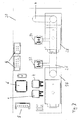
- Fig. 2 shows a schematic representation of the core of the insufflator Fig. 1 namely, the multilayer board 20 with the electronic and fluidic devices mounted thereon, which are required for the insufflator exemplified.
- the valves 28 and 30 power electronic components 4, which are connected to the valves 28 and 30 via interconnects 3, the pressure sensors 32 and 34, a connector 5 for connecting to the in Fig. 1 Power connection 16, not shown, a valve control, a sensor signal conditioning, a microcontroller 6, buttons and displays.
- the flow channels inside the multilayer board are in Fig. 2 not recognizable.
- the fluidic components provide the fluidic connection between the supply port 22 and the discharge port 14 and the valves 28 and 30th and pressure sensors 32 and 34 which are also mounted as pneumatic (fluidic) components on the circuit board 20.
- the fluidic components are arranged such that they have both fluidic contact with the flow channels arranged in the interior of the circuit board 20 and electrical contact with the electrical and electronic components 4 and 6 of the insufflator. This dual use of the board 20 allows a compact and inexpensive construction of an insufflator.
- FIG. 12 schematically shows the layout of the board 20 including the flow channel 26, the power electronic devices 4, the microcontroller 6, a plurality of connectors 5, the assembled valves 28 and 30, the pressure sensors 32 and 34, and a flow channel exit 8 which may be used in FIG Fig. 3 not shown discharge lead 14 leads.
- This multilayer board 20 represents an important innovation of the insufflator according to the invention. Crucial for this are the cavities in the interior of the board 20, which are produced by bonding individual circuit boards with a suitable layout over a large area and in a gas-tight manner. Such a multilayer board differs from known standard technologies for the production of multilayer printed circuit boards, since the individual circuit boards must first be completely coated with a suitable adhesive and then pressed.
Landscapes
- Health & Medical Sciences (AREA)
- Engineering & Computer Science (AREA)
- Hematology (AREA)
- Anesthesiology (AREA)
- Biomedical Technology (AREA)
- Heart & Thoracic Surgery (AREA)
- Microelectronics & Electronic Packaging (AREA)
- Life Sciences & Earth Sciences (AREA)
- Animal Behavior & Ethology (AREA)
- General Health & Medical Sciences (AREA)
- Public Health (AREA)
- Veterinary Medicine (AREA)
- Measuring Volume Flow (AREA)
Description
- Die Erfindung betrifft einen Insufflator.
- Insufflatoren werden in der Laparoskopie (der endoskopischen Abdominalchirurgie) eingesetzt und dienen dazu, einem Operateur durch ein Endoskop eine freie Sicht auf ein Operationsfeld im Abdomen zu verschaffen, indem in das Abdomen Kohlendioxid (CO2) eingeleitet wird. Hierzu wird über eine sog. Verres-Kanüle oder einen Trocar CO2-Gas mit einem maximalen Druck von 30 mmHg in das Abdomen insuffliert. Durch den steigenden Innendruck wird die Bauchdecke (Perituneum) angehoben und im Abdomen entsteht der gewünschte Hohlraum, der die endoskopische Betrachtung des Operationsfeldes erlaubt. Derartige CO2-Insufflatoren sind grundsätzlich bekannt.
- Aus dem Stand der Technik beim Bau von Insufflatoren sind zwei grundlegende Prinzipien bekannt.
- Gemäß dem ersten Prinzip sind die pneumatischen Bauteile am Gehäuse des Gerätes fest verschraubt. Die Verbindung zwischen den pneumatischen Bauteilen erfolgt per Schlauch. Die Verbindung der pneumatischen Bauteile mit der Elektronik (z.B. für Ventile und Drucksensoren) erfolgt per Kabel. Der Fertigungsaufwand ist hoch. Die Schläuche müssen zugeschnitten, aufgesteckt und gesichert werden. Die Kabel müssen konfektioniert werden. Diese Tätigkeiten können nicht maschinell durchgeführt werden. Durch die manuelle Fertigung und den monotonen Ablauf ist die Fehlerhäufigkeit hoch.
- Gemäß dem zweiten Prinzip werden die pneumatischen Bauteile auf einem Block integriert. In diesem Block sind alle pneumatischen Verbindungen realisiert. Die pneumatischen Bauteile werden auf diesen Block aufgeschraubt. Eine Verschlauchung ist nicht oder kaum erforderlich. Die Verbindung der pneumatischen Bauteile mit der Elektronik wird über Kabel realisiert. Durch das zweite Prinzip wird die Verschlauchung mit all ihren Fehlermöglichkeiten eingespart.
- Es ist bereits ein laparoskopischer Insufflator bekannt, der einen Zuleitungsanschluss, einen Ableitungsanschluss und eine zwischen diesen Anschlüssen angeordnete Druck- und Strömungsmesseinrichtung aufweist. Die Messeinrichtung dient zum Bestimmen des Gasdrucks und des Gasvolumenstroms am Ableitungsanschluss. Die Bauelemente sind als diskrete Teile innerhalb eines Gehäuses angeordnet (
US 6,299,592 B1 ). - Weiterhin ist ein Gerät mit fluidischen und elektrischen Eigenschaften bekannt, das einen Strömungskanal in einem plattenartigen Modul aus Halbleitermaterial oder Glasmaterial aufweist (
WO 2007/114.687 A1 ). - Ebenfalls bekannt sind fluidische Mikrosystem aus Leiterplatten, bei denen zwischen den Leiterplatten Hohlräume gebildet sind. Die Leiterplatten sind auf ihren einander zugewandten in die Hohlräume gerichteten Seiten mit Leiterbahnen versehen (
DE 197 39722 A1 ). - Darüber hinaus ist es bekannt, auf einer aus mehreren einzelnen Platten bestehenden Platte Bauelemente anzubringen, die durch innerhalb der Platte verlaufende Kanäle miteinander verbunden sind. Die Platte besteht vorzugsweise aus Aluminium (
EP 1 596 455 A1 ). - Ausgehend von bekannten Insufflatoren ist das Ziel der Erfindung, einen verbesserten Insufflator zu schaffen, der infolge einfachen Aufbaus wirtschaftlich gefertigt werden kann, zuverlässig ist und auch ausreichend hohe Volumenströme zulässt.
- Erfindungsgemäß wird diese Aufgabe durch einen Insufflator gelöst, der in üblicher Manier einen Zuleitungsanschluss und einen Ableitungsanschluss und eine zwischen diesen Anschlüssen angeordnete Druck- und Strömungsmesseinrichtung aufweist. Die Druck- und Strömungsmesseinrichtung ist zum Bestimmen von einem am Ableitungsanschluss anliegenden Gasdruck und eines am Ableitungsanschluss anliegenden Gasvolumenstroms ausgebildet. Erfindungsgemäß umfasst die Druck- und Strömungsmesseinrichtung eine mehrschichtige Platine, die in ihrem Inneren wenigstens einen Strömungskanal aufweist, der an seinem Eingang mit dem Zuleitungsanschluss und an seinem Ausgang mit dem Ableitungsanschluss verbunden ist. Auf der Platine sind Druckmesssensoren sowie elektronische Bauelemente zur Beschaltung der Druckmesssensoren angeordnet. Die Druckmesssensoren sind jeweils durch eine entsprechende Öffnung mit einer den Strömungskanal im Übrigen dicht abdeckenden Platinenschicht mit dem Strömungskanal in unmittelbarer Verbindung und ausgebildet, einen am Ort der jeweiligen Öffnung herrschenden statischen Druck repräsentierenden Ausgangswert zu liefern.
- Ein Vorteil der Erfindung besteht darin, dass die Platine, die den Strömungskanal einschließt, im Übrigen solchen Leiterplatten entspricht, wie sie in bekannten Geräten für elektronische Komponenten verwendet werden, so dass die elektronischen Komponenten über die Platine mit den ansonsten separat realisierten fluidischen Elementen eines Insufflators zu einer Baugruppe zusammengefasst werden. Dies führt in vorteilhafter Weise zu einer monolithischen Integration von Elektronik und Fluidik auf einer gemeinsamen Basis. Dadurch entfällt der sonst übliche Verschlauchungs- und Verdrahtungsaufwand. Dies wiederum vereinfacht die Herstellung und erhöht die Zuverlässigkeit. Die Herstellung kann auch einfach automatisiert werden. Schließlich kann der Insufflator - auch im Vergleich zu bekannten Insufflatoren - äußerst kompakt aufgebaut werden. Durch die Verwendung von Leiterplattenmaterial als Basis für die Platine des erfindungsgemäßen Insufflators können weiter Kosten reduziert werden. Leiterplatten und die dazugehörige Technologie sind weit verbreitet und sind sehr kostengünstig.
- In einer bevorzugten Ausführungsform des Insufflators sind bei der mehrschichtigen Platine demnach alle Platinen herkömmliche glasfaserverstärkte Epoxidharzleiterplatten, beispielsweise solche mit einer Materialkennung FR4.
- Allerdings ist die heute bekannte Standard-Leiterplattentechnologie nicht in der Lage, fluidische Funktionen zu übernehmen. Diese bisher geltende Beschränkung wird durch eine Platine überwunden, die in ihrem Inneren einen Strömungskanal aufweist und beispielsweise als mehrschichtige Platine aufgebaut sein kann.
- Dies erlaubt - wie bereits gesagt - einen monolithischen Aufbau durch automatisierte Fertigung. Der gesamte CO2-Insufflator, der auch das Netzteil einschließen kann, wird auf Basis einer mehrschichtigen Platine durch Automaten gefertigt. Es ist dann nur noch der Einbau in ein klinisch taugliches Gerät, die Kalibrierung und die Endkontrolle erforderlich.
- Die so erzielte Vereinfachung kann zu einer Einsparung in der Größenordnung bis 70 % der Fertigungskosten heutiger Insufflatoren führen. Vorzugsweise sind der Zuleitungsanschluss und der Ableitungsanschluss sowie die Drucksensoren jeweils derart gasdicht auf die mehrschichtige Platine aufgeklebt, dass der Zuleitungsanschluss, der Ableitungsanschluss und die Drucksensoren mit dem von dem Hohlraum der Platine gebildeten Strömungskanal verbunden und somit pneumatisch miteinander verbunden sind. Durch das Aufkleben der fluidischen Komponenten (Zuleitungsanschluss, Ableitungsanschluss und Drucksensoren) auf die Platine ist es möglich, diese Komponenten gasdicht und fest mit der Platine zu verbinden. Ein geeigneter Klebstoff ist beispielsweise der Klebstoff, der auch zum Fixieren der üblichen elektronischen Komponenten auf der Platine vor dem Verlöten dieser Komponenten verwendet wird. Auf diese Weise ist eine besonders einfache automatische Fertigung möglich, die gleichzeitig zu einem qualitativ hochwertigen Ergebnis führt.
- Alternativ sind der Zuleitungsanschluss und der Ableitungsanschluss sowie die Drucksensoren jeweils über Schrauben oder andere Befestigungsmittel mit der mehrschichtigen Platine verbunden.
- Die Drucksensoren sind auf der mehrschichtigen Platine vorzugsweise so angeordnet, dass sie rückwärtig auf der Platine aufgeklebt sind und auf diese Weise mit dem Strömungskanal fluidverbunden sind. Als eine Konsequenz sind die Drucksensoren im Betrieb des Insufflators rückwärtig mit Druck beaufschlagt. Der Begriff "rückwärtig" ist hier so zu verstehen, dass diejenige Öffnung eines üblichen Differenz-Drucksensors, die üblicherweise mit der Umgebungsluft in unmittelbarer Verbindung steht, bei der bevorzugten Ausführungsvariante mit dem Strömungskanal in Verbindung steht, während die andere, üblicherweise dem zu messenden Druck zugewandte Öffnung eines üblichen Drucksensors zum Umgebungsdruck hin offen ist. Alternativ können die Drucksensoren auch umgekehrt angeordnet sein.
- Vorzugsweise sind die Drucksensoren darüber hinaus mit ihren elektrischen Anschlüssen auf die Platine gelötet. Hierzu weist die Platine vorzugsweise elektrische Leiterbahnen auf. Damit ist eine weitere sichere mechanische und elektrische Verbindung dieser Drucksensoren mit der Platine und den übrigen elektronischen Komponenten des Insufflators gegeben. Diese übrigen Komponenten sind vorzugsweise ebenfalls auf die Platine gelötet und über Leiterbahnen auf der mehrschichtigen Platine miteinander und mit den Drucksensoren verbunden.
- Außerdem sind vorzugsweise ein oder mehrere Ventile auf der Platine derart angebracht, dass sie mit den Strömungskanälen fluidverbunden und im Betrieb des Insufflators mit Druck und Flow beaufschlagt werden. Die Ventile weisen elektrische Anschlüsse auf, die vorzugsweise mit Leiterbahnen der Platine verlötet sind.
- In einer bevorzugten Ausführungsform des Insufflators ist der Strömungskanal von einem Hohlraum in der mehrschichtigen Platine gebildet, der derart geformt ist, dass er einen Abschnitt aufweist, der als Strömungsdrossel wirkt und eine Volumenstrommessung nach dem Prinzip des Pneumotachographen erlaubt.
- Für eine Volumenstrommessung weist die Strömungsdrossel in einer bevorzugten Ausführungsform beispielsweise folgende Dimensionen auf: Kanallänge von etwa 60 mm, Kanalhöhe von etwa 1 mm und einen Kanalbreite von etwa 6 mm.
- Bevorzugt ist am Eingang und am Ausgang des als Strömungsdrossel wirkenden Abschnitts des Hohlraums jeweils ein Drucksensor angeordnet, der jeweils mit elektronischen Komponenten verbunden ist, wobei die Drucksensoren ausgebildet sind, eine Differenz zwischen dem statischen Druck am Eingang des als Strömungsdrossel wirkenden Abschnitts des Hohlraums und dem statischen Druck am Ausgang des als Strömungsdrossel wirkenden Abschnitts des Hohlraums zu bestimmen.
- Der Insufflator ist demnach bevorzugt dazu ausgebildet, eine Strömungsregelung durch eine Druckregelung zu implementieren. Dazu ist der Insufflator in einer Ausführungsform ausgebildet, nach einem Niederdruckprinzip zu verfahren, bei dem der Insufflationsdruck gleich einem Solldruck ist, der in der Regel einem theoretischen maximalen Druck im Abdomen entspricht. Aufgrund eines Druckabfalls über einen Einlass und entlang einer Wandung eines zum Abdomen führenden Schlauches herrscht im Abdomen tatsächlich ein niedriger Druck als der Solldruck. Dieses Verfahren stellt meistens ein kontinuierliches Verfahren dar.
- In einer anderen Ausführungsform ist der Insufflator ausgebildet, nach einem Überdruckprinzip zu arbeiten, bei dem der Insufflationsdruck stufenweise höher als der Solldruck eingestellt wird, wobei hier eine Messung eines intraabdominellen Drucks zyklisch in Pausen erfolgt, in denen der Insufflationsdruck und der Volumenstrom auf einen Betrag von jeweils etwa Null eingestellt werden. Dieses Überdruckverfahren stellt zumeist ein intermittierendes Verfahren dar.
- In einer bevorzugten Ausführungsform ist der Insufflator ausgebildet, das Gas gemäß dem aus der Veröffentlichung der europäischen Patentanmeldung
EP 1 352 669 A1 bekannten quasi-kontinuierlichen Verfahren in den Körper des Patienten einzuleiten. Auf diese Veröffentlichung, insbesondere auf die Ausführungsbeispiele gemäß den Figuren 4 und 5, wird hiermit explizit verwiesen. Demnach ist der Insufflator bevorzugt ausgebildet, die Insufflation des Gases in Abhängigkeit von einem vorgebbaren Zieldruck im Körper und dem Volumenstrom durchzuführen, bei einem Istdruck im Körper des Patienten kleiner als der Zieldruck das Gas mit Überdruck größer als der Zieldruck zu insufflieren, zum Ermitteln einer Differenz und einer Regelung zwischen Zieldruck und Istdruck im Körper den Volumenstrom während der Insufflation mit Überdruck zyklisch bis zum Zieldruck oder einem niedrigeren Solldruck zu reduzieren und den Wert des gemessenen Volumenstroms beim Zieldruck oder Solldruck als Regelgröße zwischen Zieldruck und Istdruck im Körper für die weitere Insufflation zu verwenden. Der Strömungskanal im Inneren der mehrschichtigen Platine wird vorzugsweise von einem Hohlraum gebildet, der eine lichte Höhe (in Dickenrichtung der Platine) von 1 mm und eine lichte Breite von 1 - 8 mm hat. Es hat sich herausgestellt, dass ein derartiger Strömungskanal zum einen leicht mit Hilfe einer mehrschichtigen Platine zu realisieren ist und im Übrigen einen Volumenstrom von mehr als 40 l/min gasförmigem CO2 zulässt. Entsprechend wird auch ein Insufflator bevorzugt, der für einen CO2-Gasvolumenstrom von mehr als 40 l/min ausgebildet ist. - Außerdem ist der Insufflator vorzugsweise für einen Ausgangsdruck (der dem Abdominaldruck entspricht) von bis zu 30 mmHg ausgebildet. Dies entspricht in etwa einem Druck von 4 kPa.
- Ein Beatmungsgerät, ein Überwachungs- oder Patientenmonitoring-Gerät und ein Blutdruckmessgerät bilden weitere Aspekte der Erfindung. Das Beatmungsgerät, Überwachungs- oder Patientenmonitoring-Gerät und Blutdruckmessgerät weisen jeweils in üblicher Manier einen Zuleitungsanschluss und einen Ableitungsanschluss und eine zwischen diesen Anschlüssen angeordnete Druck- und Strömungsmesseinrichtung auf. Die Druck- und Strömungsmesseinrichtung ist zum Bestimmen von einem am Ableitungsanschluss anliegenden Gasdruck und eines am Ableitungsanschluss anliegenden Gasvolumenstroms ausgebildet. Erfindungsgemäß umfasst die Druck- und Strömungsmesseinrichtung eine mehrschichtige Platine, die in ihrem Inneren wenigstens einen Strömungskanal aufweist, der an seinem Eingang mit dem Zuleitungsanschluss und an seinem Ausgang mit dem Ableitungsanschluss verbunden ist. Auf der Platine sind Druckmesssensoren sowie elektronische Bauelemente zur Beschaltung der Druckmesssensoren angeordnet. Die Druckmesssensoren sind jeweils durch eine entsprechende Öffnung mit einer den Strömungskanal im Übrigen dicht abdeckenden Platinenschicht mit dem Strömungskanal in unmittelbarer Verbindung und ausgebildet, einen am Ort der jeweiligen Öffnung herrschenden statischen Druck repräsentierenden Ausgangswert zu liefern.
- Das Beatmungsgerät, das Überwachungs- bzw. Patientenmonitoring-Gerät und das Blutdruckmessgerät teilen weitestgehend die Vorteile des erfindungsgemäßen Insufflators.
- Gegenstand der vorliegenden Erfindung ist auch ein Verfahren zum Herstellen eines Insufflators, welches die Schritte umfasst:
- Bereitstellen einer mehrschichtigen Platine mit integriertem Strömungskanal;
- Bestücken der Platine mit fluidischen Bauelementen durch Aufkleben der fluidischen Bauelemente;
- Bestücken der Platine mit elektrischen Bauelementen durch Auflöten der elektrischen Bauelemente.
- Vorzugsweise umfasst der Verfahrensschritt des Bestückens der Platine mit fluidischen Bauelementen das Auftragen von Klebstoff mittels eines Dispensers. Vorzugsweise erfolgt dieser Kleberauftrag in der bei einer Bestückung von elektronischen Bauelementen in SMD-Technik (SMD: Surface Mounted Device) üblichen Manier.
- Weitere vorteilhafte Ausgestaltungen des erfindungsgemäßen Insufflators ergeben sich aus der nachfolgenden Beschreibung eines Ausführungsbeispiels.
- Die Erfindung soll nun anhand eines Ausführungsbeispiels mit Bezug auf die Figuren näher erläutert werden. Von den Figuren zeigt:
- Fig. 1:
- Einen schematischen Querschnitt durch einen erfindungsgemäßen Insufflator;
- Fig. 2:
- eine schematische Darstellung einer Aufsicht auf eine bestimmte mehrschichtige Platine des erfindungsgemäßen Insufflators; und
- Fig. 3:
- in schematischer Darstellung das prinzipielle Layout der Platine aus
Fig. 2 . - In
Fig. 1 ist schematisch ein Gehäuse 10 eines Insufflators angedeutet, an welchem ein CO2-Anschluss 12 zum Anschluss an eine Quelle für gasförmiges CO2 vorgesehen ist sowie einen Ableitungsanschluss 14, an den ein Schlauch zum Einführen in das Abdomen eines Patienten anzuschließen ist. Außerdem weist der Insufflator gemäßFig. 1 einen elektrischen Netzanschluss 16 sowie ein Bedienpanel 18 auf. - Kernstück des Insufflators aus
Fig. 1 ist eine mehrschichtige Platine 20, auf die ein Zuleitungsanschluss 22 und der Ableitungsanschluss 14 gasdicht aufgeklebt sind. Der Zuleitungsanschluss 22 ist mit dem CO2-Anschluss 12 über einen entsprechenden Schlauch 11 verbunden. - Die Platine 20 ist mehrschichtig und weist in ihrem Inneren Hohlräume auf, die einen mehrteiligen Strömungskanal 26 bilden. Der Zuleitungsanschluss 22 und der Ableitungsanschluss 14 sind mit diesem Strömungskanal 26 fluidverbunden. Außerdem sind auf der Außenseite der Platine 20 elektrische und elektronische Bauteile des Insufflators montiert sowie Ventile 28 und 30 und Drucksensoren 32 und 34. Die Ventile 28 und 30 und die Drucksensoren 32 und 34 sind ebenfalls gasdicht auf die Platine 20 aufgeklebt. Die Drucksensoren 32 und 34 sind Differenzdrucksensoren, die rückwärtig auf die Platine 20 gasdicht aufgeklebt sind.
- Die verschiedenen Abschnitte des Strömungskanals 26 im Inneren der Platine 20 haben eine lichte Höhe von 1 mm und eine lichte Breite zwischen 1 mm und 8 mm.
- Der Insufflator erlaubt einen Gasvolumenstrom von CO2 von bis zu 44 l/min. Er ist für einen Intraabdominaldruck von 1 bis 30 mmHg ausgelegt. Durch die Ventile 28 und 30 ist ein intermittierender Gasfluss möglich.
-
Fig. 2 zeigt in schematischer Darstellung das Kernstück des Insufflators ausFig. 1 , nämlich die mehrschichtige Platine 20 mit den darauf montierten elektronischen und fluidischen Bauelementen, die für den beispielhaft dargestellten Insufflator erforderlich sind. Dies sind die Ventile 28 und 30, leistungselektronische Bauelemente 4, welche mit den Ventilen 28 bzw. 30 über Leiterbahnen 3 verbunden sind, die Drucksensoren 32 und 34, einen Steckverbinder 5 zum Verbinden mit dem inFig. 1 nicht dargestellten Netzanschluss 16, , eine Ventilansteuerung, eine Sensorsignalaufbereitung, ein Mikrocontroller 6, Tasten und Anzeigen. Die Strömungskanäle im Inneren der mehrschichtigen Platine sind inFig. 2 nicht zu erkennen. Sie stellen die fluidische Verbindung zwischen dem Zuleitungsanschluss 22 und dem Ableitungsanschluss 14 sowie den Ventilen 28 und 30 und Drucksensoren 32 und 34 dar, die als pneumatische (fluidische) Bauelemente ebenfalls auf der Platine 20 befestigt sind. Die fluidischen Bauelemente sind dabei so angeordnet, dass sie sowohl fluidischen Kontakt zu den im Inneren der Platine 20 angeordneten Strömungskanälen als auch elektrischen Kontakt zu den elektrischen und elektronischen Bauelementen 4 und 6 des Insufflators haben. Diese doppelte Nutzung der Platine 20 ermöglicht einen kompakten und preiswerten Aufbau eines Insufflators. - In
Fig. 3 zeigt in schematischer Darstellung das Layout der Platine 20 einschließlich des Strömungskanals 26, der leistungselektronischen Bauelemente 4, des Mikrocontrollers 6, einer Vielzahl Steckverbinder 5, der montierten Ventile 28 und 30, der Drucksensoren 32 und 34 und einem Strömungskanalausgangs 8, welcher zum inFig. 3 nicht dargestellten Ableitungsanschluss 14 führt. Diese mehrschichtige Platine 20 stellt eine wichtige Neuerung des erfindungsgemäßen Insufflators dar. Entscheidend hierfür sind die Hohlräume in Inneren der Platine 20, die dadurch erzeugt werden, dass einzelne Leiterplatten mit geeignetem Layout großflächig und gasdicht miteinander verklebt werden. Eine derartige mehrschichtige Platine weicht von bekannten Standardtechnologien für die Herstellung von Multilayer-Leiterplatten ab, da die einzelnen Leiterplatten zunächst vollständig mit einem geeigneten Klebstoff beschichtet und anschließend verpresst werden müssen. - Bekannte Verklebungstechniken von bekannten Multilayer-Leiterplatten unterscheiden sich von der erfindungsgemäßen mehrschichtigen Platine dadurch, dass sie üblicherweise nicht gasdicht miteinander verklebt sind, während dies bei der mehrschichtigen Platine 20 erfindungsgemäß der Fall ist.
-
- 3
- Leiterbahnen
- 4
- leistungselektronische Bauelemente
- 5
- Steckverbinder
- 6
- Mikrocontroller
- 8
- Ausgang des Strömungskanals 26
- 10
- Gehäuse eines Insufflators
- 11
- Schlauch
- 12
- CO2-Anschluss
- 14
- Ableitungsanschluss
- 16
- Netzanschluss
- 18
- Bedienpanel
- 20
- mehrschichtige Platine
- 22
- Zuleitungsanschluss
- 26
- Strömungskanal
- 28,30
- Ventile
- 32,34
- Drucksensoren
Claims (14)
- Insufflator mit einem Zuleitungsanschluss (22) und einem Ableitungsanschluss (14) und einer zwischen diesen Anschlüssen (22, 14) angeordneten Druck- und Strömungsmesseinrichtung zum Bestimmen von einen am Ableitungsanschluss (14) anliegenden Gasdruck und einen am Ableitungsanschluss (14) anliegenden Gasvolumenstrom charakterisierenden Messgrößen,
dadurch gekennzeichnet, dass die Druck- und Strömungsmesseinrichtung eine mehrschichtige Platine (20) umfasst, die in ihrem Inneren wenigstens einen Strömungskanal (26) umfasst, der an seinem Eingang mit dem Zuleitungsanschluss (22) und an seinem Ausgang (8) mit dem Ableitungsanschluss (14) verbunden ist,
wobei auf der Platine (20) Druckmesssensoren (32, 34) sowie elektronische Bauelemente (4, 6) zur Beschaltung der Druckmesssensoren (32, 34) angeordnet sind, von denen die Druckmesssensoren (32, 34) jeweils durch eine entsprechende Öffnung einer den Strömungskanal (26) im Übrigen dicht abdeckenden Platinenschicht mit dem Strömungskanal (26) in unmittelbarer Verbindung stehen und ausgebildet sind, einen den am Ort der jeweiligen Öffnung herrschenden statischen Druck repräsentierenden Ausgangswert zu liefern. - Insufflator nach Anspruch 1, dadurch gekennzeichnet, dass der Zuleitungsanschluss (22) und der Ableitungsanschluss (14) sowie die Drucksensoren (32, 34) jeweils derart gasdicht auf die den Strömungskanal (26) bedeckende Schicht der Platine (20) aufgeklebt sind, dass der Zuleitungsanschluss (22), der Ableitungsanschluss (14) und die Drucksensoren (32, 34) über den Strömungskanal (26) pneumatisch miteinander verbunden sind.
- Insufflator nach Anspruch 2, dadurch gekennzeichnet, dass die Drucksensoren (32, 34) rückwärtig mit dem Strömungskanal (26) fluidverbunden und im Betrieb des Insufflators rückwärtig mit Druck beaufschlagt sind.
- Insufflator nach einem der Ansprüche 1 bis 3, dadurch gekennzeichnet, dass die Drucksensoren (32, 34) mit ihren elektrischen Anschlüssen auf die Platine (20) gelötet sind.
- Insufflator nach einem der Ansprüche 1 bis 4, gekennzeichnet durch wenigstens ein Ventil (28, 30), das mit dem Strömungskanal (26) derart fluidverbunden ist, dass es im Betrieb des Insufflators mit Druck und einem Gasvolumenstrom beaufschlagt wird.
- Insufflator nach Anspruch 5, dadurch gekennzeichnet, dass das Ventile (28, 30) elektrische Anschlüsse aufweist, die auf die Platine (20) gelötet sind.
- Insufflator nach einem der Ansprüche 1 bis 5, dadurch gekennzeichnet, dass der Strömungskanal (26) von einem Hohlraum in der mehrschichtigen Platine (20) gebildet ist, der derart geformt ist, dass er einen Abschnitt aufweist, der als Strömungsdrossel wirkt und eine Volumenstrommessung nach dem Prinzip des Pneumotachographen erlaubt.
- Insufflator nach Anspruch 7, dadurch gekennzeichnet, dass am Eingang und am Ausgang (8) des als Strömungsdrossel wirkenden Abschnitts des Hohlraums jeweils ein Drucksensor (32, 34) angeordnet ist, die mit elektronischen Komponenten verbunden (4, 6) sind, die ausgebildet sind, eine Differenz zwischen dem statischen Druck am Eingang des als Strömungsdrossel wirkenden Abschnitts des Hohlraums und dem statischen Druck am Ausgang des als Strömungsdrossel wirkenden Abschnitts des Hohlraums zu bestimmen.
- Insufflator nach einem der Ansprüche 1 bis 8, dadurch gekennzeichnet, dass der Strömungskanal (26) eine lichte Höhe von 1 mm und eine lichte Breite von 1 mm bis 8 mm hat.
- Insufflator nach einem der Ansprüche 1 bis 9, dadurch gekennzeichnet, dass der Insufflator für einen CO2 Gasvolumenstrom von mehr als 40 l/min ausgebildet ist.
- Insufflator nach einem der Ansprüche 1 bis 10, dadurch gekennzeichnet, dass der Insufflator für einen Eingangsgasdruck (Abdominaldruck) von bis zu mindestens 30 mmHg ausgebildet ist.
- Verfahren zum Herstellen eines Insufflators nach einem der vorhergehenden Ansprüche, welches die Schritte umfasst:- Bereitstellen einer mehrschichtigen Platine (20) mit integriertem Strömungskanal (26);- Bestücken der Platine (20) mit fluidischen Bauelementen durch Aufkleben der fluidischen Bauelemente;- Bestücken der Platine (20) mit elektronischen Bauelementen (4, 6) durch Auflöten der elektronischen Bauelemente (4, 6).
- Verfahren nach Anspruch 12, bei dem der Verfahrensschritt des Bestückens der Platine (20) mit fluidischen Bauelementen das Auftragen von Klebstoff mittels eines Dispensers einschließt.
- Verfahren nach Anspruch 13, bei dem der Auftrag von Klebstoff in der bei einer Bestückung von elektronischen Bauelementen (4, 6) in SMD-Technik üblichen Manier erfolgt.
Applications Claiming Priority (2)
| Application Number | Priority Date | Filing Date | Title |
|---|---|---|---|
| DE200910007393 DE102009007393A1 (de) | 2009-01-29 | 2009-01-29 | Insufflator |
| PCT/EP2010/051095 WO2010086412A1 (de) | 2009-01-29 | 2010-01-29 | Insufflator |
Publications (2)
| Publication Number | Publication Date |
|---|---|
| EP2391414A1 EP2391414A1 (de) | 2011-12-07 |
| EP2391414B1 true EP2391414B1 (de) | 2019-04-10 |
Family
ID=42077039
Family Applications (1)
| Application Number | Title | Priority Date | Filing Date |
|---|---|---|---|
| EP10701387.2A Active EP2391414B1 (de) | 2009-01-29 | 2010-01-29 | Insufflator |
Country Status (4)
| Country | Link |
|---|---|
| US (1) | US9138549B2 (de) |
| EP (1) | EP2391414B1 (de) |
| DE (1) | DE102009007393A1 (de) |
| WO (1) | WO2010086412A1 (de) |
Families Citing this family (11)
| Publication number | Priority date | Publication date | Assignee | Title |
|---|---|---|---|---|
| DE102011003007A1 (de) * | 2011-01-21 | 2012-07-26 | Mgb Endoskopische Geräte Gmbh Berlin | Leiterplatte mit Überdruckventil, Insufflator |
| DE102012009078A1 (de) | 2012-05-09 | 2013-11-14 | Karl Storz Gmbh & Co. Kg | Insufflationsvorrichtung und Verfahren |
| DE202015000540U1 (de) * | 2015-01-27 | 2015-04-10 | Kendrion Kuhnke Automotive GmbH | Pneumatische Steuer- und Messvorrichtung sowie Sitzkomfortsystem |
| US10646667B2 (en) | 2017-05-31 | 2020-05-12 | Lexion Medical, Llc | Method and system for controlling pressurization of a patient cavity using a pressure sensor in a trocar |
| US10595897B2 (en) | 2016-08-30 | 2020-03-24 | Lexion Medical, Llc | Method and system for measuring pressure in a body cavity using a trocar |
| US11433190B2 (en) | 2017-05-31 | 2022-09-06 | Lexion Medical, Llc | Method and system for controlling pressurization of a patient cavity using a pressure sensor of a medical appliance |
| CN105571653B (zh) * | 2015-12-17 | 2019-02-15 | 广东电网有限责任公司电力科学研究院 | 磨煤机风量测量方法和系统 |
| US10835284B2 (en) | 2016-10-13 | 2020-11-17 | Lexion Medical, Llc | Method and system for controlling pressurization of a patient cavity using cavity distension measured by a pressure sensor of a trocar |
| US10357283B2 (en) | 2017-01-04 | 2019-07-23 | Lexion Medical, Inc. | Method and system for determining pressure and flow restrictions in a body cavity using a trocar |
| CN111388031B (zh) * | 2019-06-28 | 2021-08-10 | 深圳迈瑞生物医疗电子股份有限公司 | 一种气腹机及内窥镜设备 |
| DE102022200556A1 (de) | 2022-01-18 | 2023-07-20 | Psa Automobiles Sa | Steuerungsanordnung zur Ansteuerung von Funktionen eines Fahrzeugsitzes für ein Fahrzeug, Fahrzeugsitz mit der Steuerungsanordnung und Fahrzeug mit dem Fahrzeugsitz |
Family Cites Families (12)
| Publication number | Priority date | Publication date | Assignee | Title |
|---|---|---|---|---|
| WO1994001154A1 (en) | 1992-07-07 | 1994-01-20 | Andronic Devices, Ltd. | Apparatus and method for improved insufflation |
| US5423741A (en) * | 1993-05-28 | 1995-06-13 | Bei Medical Sytems, Inc. | Apparatus and method for the insufflation of gas into a body cavity |
| DE19739722A1 (de) * | 1997-09-10 | 1999-04-01 | Lienhard Prof Dr Pagel | Zwei- und Dreidimensionale fluidische Mikrosysteme aus Leiterplatten |
| US6299592B1 (en) * | 1998-03-31 | 2001-10-09 | Northgate Technologies Inc. | Laparoscopic insufflator |
| US7017792B2 (en) | 2001-02-02 | 2006-03-28 | Mitsubishi Heavy Industries, Ltd. | Integrated piping plate, machining method for same, machining apparatus for same, and machining equipment for same |
| DE10215955A1 (de) | 2002-04-11 | 2003-10-23 | Wisap Gmbh | Verfahren zur Insufflation von Gas |
| EP1556121B1 (de) * | 2002-10-28 | 2016-06-01 | Northgate Technologies Incorporated | Insufflationssystem mit einem Insufflatorschlauch mit mehrfacher Kapazität |
| US7641668B2 (en) * | 2003-05-16 | 2010-01-05 | Scimed Life Systems, Inc. | Fluid delivery system and related methods of use |
| JP4624707B2 (ja) * | 2004-03-31 | 2011-02-02 | オリンパス株式会社 | 内視鏡外科手術システム |
| DE102005052122A1 (de) * | 2005-10-28 | 2007-05-10 | W.O.M. World Of Medicine Ag | Schlauchset |
| NL1031465C2 (nl) | 2006-03-30 | 2007-10-03 | C2V B V | Werkwijze voor het opbouwen van een inrichting met fluïdische en elektrische functies. |
| US8269638B2 (en) * | 2008-01-23 | 2012-09-18 | Lexion Medical Llc | Hydration alert |
-
2009
- 2009-01-29 DE DE200910007393 patent/DE102009007393A1/de not_active Withdrawn
-
2010
- 2010-01-29 EP EP10701387.2A patent/EP2391414B1/de active Active
- 2010-01-29 US US13/146,500 patent/US9138549B2/en active Active
- 2010-01-29 WO PCT/EP2010/051095 patent/WO2010086412A1/de not_active Ceased
Non-Patent Citations (1)
| Title |
|---|
| None * |
Also Published As
| Publication number | Publication date |
|---|---|
| US9138549B2 (en) | 2015-09-22 |
| US20110308326A1 (en) | 2011-12-22 |
| WO2010086412A1 (de) | 2010-08-05 |
| DE102009007393A1 (de) | 2010-08-05 |
| EP2391414A1 (de) | 2011-12-07 |
Similar Documents
| Publication | Publication Date | Title |
|---|---|---|
| WO2010086412A1 (de) | Insufflator | |
| EP2561729B1 (de) | Leiterplatte mit hohlraum | |
| EP1887930B1 (de) | Implantierbare vorrichtung zur erfassung von intracraniellen drücken | |
| EP0372093B1 (de) | Einrichtung zur diagnostik und behandlung von nasenerkrankungen | |
| EP1248558A1 (de) | Blutdruckmessgerät und verfahren zur herstellung eines teileträgers eines blutdruckmessgeräts | |
| EP3206386A1 (de) | Baugruppe für ein videoendoskop | |
| EP2916120A1 (de) | Sensorblock, Rohr sowie Herstellungsverfahren | |
| EP1152231A2 (de) | Drucksensorvorrichtung | |
| DE102005009620A1 (de) | Ultraschallsensor | |
| EP2435810B1 (de) | Steuergerät mit drucksensor | |
| WO2014108119A1 (de) | Elektronische baugruppe mit einem gehäuse mit einem druckausgleichselement zwischen dem gehäuseinneren und der umgebung | |
| EP2893303A1 (de) | Ultraschallwandler und verfahren zur herstellung eines ultraschall-wandlers | |
| DE102006008752A1 (de) | Verfahren zum Herstellen einer Fluiddruckmesseinheit und Komponente zum Einsatz in einer Fluiddruckmesseinheit | |
| EP1605238B1 (de) | Elektronischer Heizkostenverteiler | |
| EP1858574A1 (de) | Beheizbares schlauchsystem | |
| DE19943367B4 (de) | Luftzufuhreinrichtung für ein Endoskop | |
| WO2015090766A1 (de) | Relativdrucksensor | |
| EP1339586A1 (de) | Sensoranordnung für einen unterdruck-bremskraftverstärker und damit ausgerüsteter unterdruck-bremskraftverstärker | |
| DE102006050351A1 (de) | Gehäuse für ein elektronisches Steuergerät | |
| EP2665954B1 (de) | Leiterplatte mit überdruckventil, insufflator | |
| EP2662106A1 (de) | Insufflationsvorrichtung | |
| DE102012213572A1 (de) | Kapazitiver Drucksensor | |
| DE102005055261B4 (de) | Ventilanordnung mit wenigstens einem Sensor | |
| WO2009100954A1 (de) | Instrument zum einführen in unzugängliche räume und verfahren zur herstellung eines endabschnitts eines solchen instruments | |
| EP3714822A1 (de) | Fluidsteueranordnung für ein medizinisches gerät |
Legal Events
| Date | Code | Title | Description |
|---|---|---|---|
| PUAI | Public reference made under article 153(3) epc to a published international application that has entered the european phase |
Free format text: ORIGINAL CODE: 0009012 |
|
| 17P | Request for examination filed |
Effective date: 20110829 |
|
| AK | Designated contracting states |
Kind code of ref document: A1 Designated state(s): AT BE BG CH CY CZ DE DK EE ES FI FR GB GR HR HU IE IS IT LI LT LU LV MC MK MT NL NO PL PT RO SE SI SK SM TR |
|
| DAX | Request for extension of the european patent (deleted) | ||
| STAA | Information on the status of an ep patent application or granted ep patent |
Free format text: STATUS: EXAMINATION IS IN PROGRESS |
|
| 17Q | First examination report despatched |
Effective date: 20161107 |
|
| GRAP | Despatch of communication of intention to grant a patent |
Free format text: ORIGINAL CODE: EPIDOSNIGR1 |
|
| STAA | Information on the status of an ep patent application or granted ep patent |
Free format text: STATUS: GRANT OF PATENT IS INTENDED |
|
| INTG | Intention to grant announced |
Effective date: 20180919 |
|
| GRAS | Grant fee paid |
Free format text: ORIGINAL CODE: EPIDOSNIGR3 |
|
| GRAJ | Information related to disapproval of communication of intention to grant by the applicant or resumption of examination proceedings by the epo deleted |
Free format text: ORIGINAL CODE: EPIDOSDIGR1 |
|
| GRAL | Information related to payment of fee for publishing/printing deleted |
Free format text: ORIGINAL CODE: EPIDOSDIGR3 |
|
| STAA | Information on the status of an ep patent application or granted ep patent |
Free format text: STATUS: EXAMINATION IS IN PROGRESS |
|
| GRAR | Information related to intention to grant a patent recorded |
Free format text: ORIGINAL CODE: EPIDOSNIGR71 |
|
| STAA | Information on the status of an ep patent application or granted ep patent |
Free format text: STATUS: GRANT OF PATENT IS INTENDED |
|
| INTC | Intention to grant announced (deleted) | ||
| GRAA | (expected) grant |
Free format text: ORIGINAL CODE: 0009210 |
|
| STAA | Information on the status of an ep patent application or granted ep patent |
Free format text: STATUS: THE PATENT HAS BEEN GRANTED |
|
| INTG | Intention to grant announced |
Effective date: 20190228 |
|
| AK | Designated contracting states |
Kind code of ref document: B1 Designated state(s): AT BE BG CH CY CZ DE DK EE ES FI FR GB GR HR HU IE IS IT LI LT LU LV MC MK MT NL NO PL PT RO SE SI SK SM TR |
|
| REG | Reference to a national code |
Ref country code: GB Ref legal event code: FG4D Free format text: NOT ENGLISH |
|
| REG | Reference to a national code |
Ref country code: CH Ref legal event code: EP Ref country code: AT Ref legal event code: REF Ref document number: 1117850 Country of ref document: AT Kind code of ref document: T Effective date: 20190415 |
|
| REG | Reference to a national code |
Ref country code: IE Ref legal event code: FG4D Free format text: LANGUAGE OF EP DOCUMENT: GERMAN |
|
| REG | Reference to a national code |
Ref country code: DE Ref legal event code: R096 Ref document number: 502010015923 Country of ref document: DE |
|
| REG | Reference to a national code |
Ref country code: NL Ref legal event code: MP Effective date: 20190410 |
|
| REG | Reference to a national code |
Ref country code: LT Ref legal event code: MG4D |
|
| PG25 | Lapsed in a contracting state [announced via postgrant information from national office to epo] |
Ref country code: NL Free format text: LAPSE BECAUSE OF FAILURE TO SUBMIT A TRANSLATION OF THE DESCRIPTION OR TO PAY THE FEE WITHIN THE PRESCRIBED TIME-LIMIT Effective date: 20190410 |
|
| PG25 | Lapsed in a contracting state [announced via postgrant information from national office to epo] |
Ref country code: ES Free format text: LAPSE BECAUSE OF FAILURE TO SUBMIT A TRANSLATION OF THE DESCRIPTION OR TO PAY THE FEE WITHIN THE PRESCRIBED TIME-LIMIT Effective date: 20190410 Ref country code: SE Free format text: LAPSE BECAUSE OF FAILURE TO SUBMIT A TRANSLATION OF THE DESCRIPTION OR TO PAY THE FEE WITHIN THE PRESCRIBED TIME-LIMIT Effective date: 20190410 Ref country code: NO Free format text: LAPSE BECAUSE OF FAILURE TO SUBMIT A TRANSLATION OF THE DESCRIPTION OR TO PAY THE FEE WITHIN THE PRESCRIBED TIME-LIMIT Effective date: 20190710 Ref country code: HR Free format text: LAPSE BECAUSE OF FAILURE TO SUBMIT A TRANSLATION OF THE DESCRIPTION OR TO PAY THE FEE WITHIN THE PRESCRIBED TIME-LIMIT Effective date: 20190410 Ref country code: PT Free format text: LAPSE BECAUSE OF FAILURE TO SUBMIT A TRANSLATION OF THE DESCRIPTION OR TO PAY THE FEE WITHIN THE PRESCRIBED TIME-LIMIT Effective date: 20190910 Ref country code: FI Free format text: LAPSE BECAUSE OF FAILURE TO SUBMIT A TRANSLATION OF THE DESCRIPTION OR TO PAY THE FEE WITHIN THE PRESCRIBED TIME-LIMIT Effective date: 20190410 Ref country code: LT Free format text: LAPSE BECAUSE OF FAILURE TO SUBMIT A TRANSLATION OF THE DESCRIPTION OR TO PAY THE FEE WITHIN THE PRESCRIBED TIME-LIMIT Effective date: 20190410 |
|
| PG25 | Lapsed in a contracting state [announced via postgrant information from national office to epo] |
Ref country code: LV Free format text: LAPSE BECAUSE OF FAILURE TO SUBMIT A TRANSLATION OF THE DESCRIPTION OR TO PAY THE FEE WITHIN THE PRESCRIBED TIME-LIMIT Effective date: 20190410 Ref country code: BG Free format text: LAPSE BECAUSE OF FAILURE TO SUBMIT A TRANSLATION OF THE DESCRIPTION OR TO PAY THE FEE WITHIN THE PRESCRIBED TIME-LIMIT Effective date: 20190710 Ref country code: GR Free format text: LAPSE BECAUSE OF FAILURE TO SUBMIT A TRANSLATION OF THE DESCRIPTION OR TO PAY THE FEE WITHIN THE PRESCRIBED TIME-LIMIT Effective date: 20190711 Ref country code: PL Free format text: LAPSE BECAUSE OF FAILURE TO SUBMIT A TRANSLATION OF THE DESCRIPTION OR TO PAY THE FEE WITHIN THE PRESCRIBED TIME-LIMIT Effective date: 20190410 |
|
| PG25 | Lapsed in a contracting state [announced via postgrant information from national office to epo] |
Ref country code: IS Free format text: LAPSE BECAUSE OF FAILURE TO SUBMIT A TRANSLATION OF THE DESCRIPTION OR TO PAY THE FEE WITHIN THE PRESCRIBED TIME-LIMIT Effective date: 20190810 |
|
| REG | Reference to a national code |
Ref country code: DE Ref legal event code: R097 Ref document number: 502010015923 Country of ref document: DE |
|
| PG25 | Lapsed in a contracting state [announced via postgrant information from national office to epo] |
Ref country code: DK Free format text: LAPSE BECAUSE OF FAILURE TO SUBMIT A TRANSLATION OF THE DESCRIPTION OR TO PAY THE FEE WITHIN THE PRESCRIBED TIME-LIMIT Effective date: 20190410 Ref country code: SK Free format text: LAPSE BECAUSE OF FAILURE TO SUBMIT A TRANSLATION OF THE DESCRIPTION OR TO PAY THE FEE WITHIN THE PRESCRIBED TIME-LIMIT Effective date: 20190410 Ref country code: EE Free format text: LAPSE BECAUSE OF FAILURE TO SUBMIT A TRANSLATION OF THE DESCRIPTION OR TO PAY THE FEE WITHIN THE PRESCRIBED TIME-LIMIT Effective date: 20190410 Ref country code: RO Free format text: LAPSE BECAUSE OF FAILURE TO SUBMIT A TRANSLATION OF THE DESCRIPTION OR TO PAY THE FEE WITHIN THE PRESCRIBED TIME-LIMIT Effective date: 20190410 Ref country code: CZ Free format text: LAPSE BECAUSE OF FAILURE TO SUBMIT A TRANSLATION OF THE DESCRIPTION OR TO PAY THE FEE WITHIN THE PRESCRIBED TIME-LIMIT Effective date: 20190410 |
|
| PLBE | No opposition filed within time limit |
Free format text: ORIGINAL CODE: 0009261 |
|
| STAA | Information on the status of an ep patent application or granted ep patent |
Free format text: STATUS: NO OPPOSITION FILED WITHIN TIME LIMIT |
|
| PG25 | Lapsed in a contracting state [announced via postgrant information from national office to epo] |
Ref country code: SM Free format text: LAPSE BECAUSE OF FAILURE TO SUBMIT A TRANSLATION OF THE DESCRIPTION OR TO PAY THE FEE WITHIN THE PRESCRIBED TIME-LIMIT Effective date: 20190410 Ref country code: IT Free format text: LAPSE BECAUSE OF FAILURE TO SUBMIT A TRANSLATION OF THE DESCRIPTION OR TO PAY THE FEE WITHIN THE PRESCRIBED TIME-LIMIT Effective date: 20190410 |
|
| 26N | No opposition filed |
Effective date: 20200113 |
|
| PG25 | Lapsed in a contracting state [announced via postgrant information from national office to epo] |
Ref country code: TR Free format text: LAPSE BECAUSE OF FAILURE TO SUBMIT A TRANSLATION OF THE DESCRIPTION OR TO PAY THE FEE WITHIN THE PRESCRIBED TIME-LIMIT Effective date: 20190410 |
|
| PG25 | Lapsed in a contracting state [announced via postgrant information from national office to epo] |
Ref country code: SI Free format text: LAPSE BECAUSE OF FAILURE TO SUBMIT A TRANSLATION OF THE DESCRIPTION OR TO PAY THE FEE WITHIN THE PRESCRIBED TIME-LIMIT Effective date: 20190410 |
|
| PG25 | Lapsed in a contracting state [announced via postgrant information from national office to epo] |
Ref country code: MC Free format text: LAPSE BECAUSE OF FAILURE TO SUBMIT A TRANSLATION OF THE DESCRIPTION OR TO PAY THE FEE WITHIN THE PRESCRIBED TIME-LIMIT Effective date: 20190410 |
|
| REG | Reference to a national code |
Ref country code: CH Ref legal event code: PL |
|
| REG | Reference to a national code |
Ref country code: BE Ref legal event code: MM Effective date: 20200131 |
|
| PG25 | Lapsed in a contracting state [announced via postgrant information from national office to epo] |
Ref country code: LU Free format text: LAPSE BECAUSE OF NON-PAYMENT OF DUE FEES Effective date: 20200129 |
|
| PG25 | Lapsed in a contracting state [announced via postgrant information from national office to epo] |
Ref country code: CH Free format text: LAPSE BECAUSE OF NON-PAYMENT OF DUE FEES Effective date: 20200131 Ref country code: BE Free format text: LAPSE BECAUSE OF NON-PAYMENT OF DUE FEES Effective date: 20200131 Ref country code: LI Free format text: LAPSE BECAUSE OF NON-PAYMENT OF DUE FEES Effective date: 20200131 |
|
| PG25 | Lapsed in a contracting state [announced via postgrant information from national office to epo] |
Ref country code: IE Free format text: LAPSE BECAUSE OF NON-PAYMENT OF DUE FEES Effective date: 20200129 |
|
| REG | Reference to a national code |
Ref country code: AT Ref legal event code: MM01 Ref document number: 1117850 Country of ref document: AT Kind code of ref document: T Effective date: 20200129 |
|
| PG25 | Lapsed in a contracting state [announced via postgrant information from national office to epo] |
Ref country code: AT Free format text: LAPSE BECAUSE OF NON-PAYMENT OF DUE FEES Effective date: 20200129 |
|
| PG25 | Lapsed in a contracting state [announced via postgrant information from national office to epo] |
Ref country code: MT Free format text: LAPSE BECAUSE OF FAILURE TO SUBMIT A TRANSLATION OF THE DESCRIPTION OR TO PAY THE FEE WITHIN THE PRESCRIBED TIME-LIMIT Effective date: 20190410 Ref country code: CY Free format text: LAPSE BECAUSE OF FAILURE TO SUBMIT A TRANSLATION OF THE DESCRIPTION OR TO PAY THE FEE WITHIN THE PRESCRIBED TIME-LIMIT Effective date: 20190410 |
|
| PG25 | Lapsed in a contracting state [announced via postgrant information from national office to epo] |
Ref country code: MK Free format text: LAPSE BECAUSE OF FAILURE TO SUBMIT A TRANSLATION OF THE DESCRIPTION OR TO PAY THE FEE WITHIN THE PRESCRIBED TIME-LIMIT Effective date: 20190410 |
|
| PGFP | Annual fee paid to national office [announced via postgrant information from national office to epo] |
Ref country code: FR Payment date: 20230123 Year of fee payment: 14 |
|
| PGFP | Annual fee paid to national office [announced via postgrant information from national office to epo] |
Ref country code: GB Payment date: 20230124 Year of fee payment: 14 Ref country code: DE Payment date: 20230102 Year of fee payment: 14 |
|
| REG | Reference to a national code |
Ref country code: DE Ref legal event code: R119 Ref document number: 502010015923 Country of ref document: DE |
|
| GBPC | Gb: european patent ceased through non-payment of renewal fee |
Effective date: 20240129 |
|
| PG25 | Lapsed in a contracting state [announced via postgrant information from national office to epo] |
Ref country code: DE Free format text: LAPSE BECAUSE OF NON-PAYMENT OF DUE FEES Effective date: 20240801 |
|
| PG25 | Lapsed in a contracting state [announced via postgrant information from national office to epo] |
Ref country code: GB Free format text: LAPSE BECAUSE OF NON-PAYMENT OF DUE FEES Effective date: 20240129 |
|
| PG25 | Lapsed in a contracting state [announced via postgrant information from national office to epo] |
Ref country code: FR Free format text: LAPSE BECAUSE OF NON-PAYMENT OF DUE FEES Effective date: 20240131 |
|
| PG25 | Lapsed in a contracting state [announced via postgrant information from national office to epo] |
Ref country code: GB Free format text: LAPSE BECAUSE OF NON-PAYMENT OF DUE FEES Effective date: 20240129 Ref country code: FR Free format text: LAPSE BECAUSE OF NON-PAYMENT OF DUE FEES Effective date: 20240131 Ref country code: DE Free format text: LAPSE BECAUSE OF NON-PAYMENT OF DUE FEES Effective date: 20240801 |