EP2391199A1 - Lightweight audio system for automotive applications and method - Google Patents
Lightweight audio system for automotive applications and method Download PDFInfo
- Publication number
- EP2391199A1 EP2391199A1 EP20110161742 EP11161742A EP2391199A1 EP 2391199 A1 EP2391199 A1 EP 2391199A1 EP 20110161742 EP20110161742 EP 20110161742 EP 11161742 A EP11161742 A EP 11161742A EP 2391199 A1 EP2391199 A1 EP 2391199A1
- Authority
- EP
- European Patent Office
- Prior art keywords
- case
- housing assembly
- sheet material
- assembly
- electronic component
- Prior art date
- Legal status (The legal status is an assumption and is not a legal conclusion. Google has not performed a legal analysis and makes no representation as to the accuracy of the status listed.)
- Withdrawn
Links
Images


Classifications
-
- H—ELECTRICITY
- H05—ELECTRIC TECHNIQUES NOT OTHERWISE PROVIDED FOR
- H05K—PRINTED CIRCUITS; CASINGS OR CONSTRUCTIONAL DETAILS OF ELECTRIC APPARATUS; MANUFACTURE OF ASSEMBLAGES OF ELECTRICAL COMPONENTS
- H05K9/00—Screening of apparatus or components against electric or magnetic fields
- H05K9/0007—Casings
- H05K9/0047—Casings being rigid plastic containers having conductive particles, fibres or mesh embedded therein
-
- B—PERFORMING OPERATIONS; TRANSPORTING
- B21—MECHANICAL METAL-WORKING WITHOUT ESSENTIALLY REMOVING MATERIAL; PUNCHING METAL
- B21D—WORKING OR PROCESSING OF SHEET METAL OR METAL TUBES, RODS OR PROFILES WITHOUT ESSENTIALLY REMOVING MATERIAL; PUNCHING METAL
- B21D26/00—Shaping without cutting otherwise than using rigid devices or tools or yieldable or resilient pads, i.e. applying fluid pressure or magnetic forces
- B21D26/02—Shaping without cutting otherwise than using rigid devices or tools or yieldable or resilient pads, i.e. applying fluid pressure or magnetic forces by applying fluid pressure
- B21D26/021—Deforming sheet bodies
- B21D26/027—Means for controlling fluid parameters, e.g. pressure or temperature
-
- B—PERFORMING OPERATIONS; TRANSPORTING
- B21—MECHANICAL METAL-WORKING WITHOUT ESSENTIALLY REMOVING MATERIAL; PUNCHING METAL
- B21D—WORKING OR PROCESSING OF SHEET METAL OR METAL TUBES, RODS OR PROFILES WITHOUT ESSENTIALLY REMOVING MATERIAL; PUNCHING METAL
- B21D26/00—Shaping without cutting otherwise than using rigid devices or tools or yieldable or resilient pads, i.e. applying fluid pressure or magnetic forces
- B21D26/02—Shaping without cutting otherwise than using rigid devices or tools or yieldable or resilient pads, i.e. applying fluid pressure or magnetic forces by applying fluid pressure
- B21D26/021—Deforming sheet bodies
- B21D26/031—Mould construction
-
- H—ELECTRICITY
- H04—ELECTRIC COMMUNICATION TECHNIQUE
- H04B—TRANSMISSION
- H04B1/00—Details of transmission systems, not covered by a single one of groups H04B3/00 - H04B13/00; Details of transmission systems not characterised by the medium used for transmission
- H04B1/06—Receivers
- H04B1/08—Constructional details, e.g. cabinet
- H04B1/082—Constructional details, e.g. cabinet to be used in vehicles
-
- H—ELECTRICITY
- H04—ELECTRIC COMMUNICATION TECHNIQUE
- H04B—TRANSMISSION
- H04B15/00—Suppression or limitation of noise or interference
- H04B15/02—Reducing interference from electric apparatus by means located at or near the interfering apparatus
-
- Y—GENERAL TAGGING OF NEW TECHNOLOGICAL DEVELOPMENTS; GENERAL TAGGING OF CROSS-SECTIONAL TECHNOLOGIES SPANNING OVER SEVERAL SECTIONS OF THE IPC; TECHNICAL SUBJECTS COVERED BY FORMER USPC CROSS-REFERENCE ART COLLECTIONS [XRACs] AND DIGESTS
- Y10—TECHNICAL SUBJECTS COVERED BY FORMER USPC
- Y10T—TECHNICAL SUBJECTS COVERED BY FORMER US CLASSIFICATION
- Y10T156/00—Adhesive bonding and miscellaneous chemical manufacture
- Y10T156/10—Methods of surface bonding and/or assembly therefor
- Y10T156/1002—Methods of surface bonding and/or assembly therefor with permanent bending or reshaping or surface deformation of self sustaining lamina
- Y10T156/1028—Methods of surface bonding and/or assembly therefor with permanent bending or reshaping or surface deformation of self sustaining lamina by bending, drawing or stretch forming sheet to assume shape of configured lamina while in contact therewith
-
- Y—GENERAL TAGGING OF NEW TECHNOLOGICAL DEVELOPMENTS; GENERAL TAGGING OF CROSS-SECTIONAL TECHNOLOGIES SPANNING OVER SEVERAL SECTIONS OF THE IPC; TECHNICAL SUBJECTS COVERED BY FORMER USPC CROSS-REFERENCE ART COLLECTIONS [XRACs] AND DIGESTS
- Y10—TECHNICAL SUBJECTS COVERED BY FORMER USPC
- Y10T—TECHNICAL SUBJECTS COVERED BY FORMER US CLASSIFICATION
- Y10T29/00—Metal working
- Y10T29/49—Method of mechanical manufacture
- Y10T29/4998—Combined manufacture including applying or shaping of fluent material
Definitions
- the present invention relates generally to apparatus for enclosing electrical subassemblies, and more specifically relates to apparatus for efficiently securing subassemblies to a chassis of an electrical assembly such as an automobile radio, compact disc playing mechanism, cassette tape playing mechanism, navigational aid, personal computer, personal and telematic communication devices or disk drive mechanism.
- an electrical assembly such as an automobile radio, compact disc playing mechanism, cassette tape playing mechanism, navigational aid, personal computer, personal and telematic communication devices or disk drive mechanism.
- Devices such as automobile radios or personal computers contain subassemblies such as cassette playing mechanisms or disk drives that are attached to the chassis using threaded fasteners.
- the chassis provides structural support for the subassemblies and also provides electromagnetic shielding to limit electromagnetic interference (EMI) experienced by, and/or created by the device.
- EMI electromagnetic interference
- the fasteners ensure that each subassembly within the chassis is properly located and securely retained within the chassis.
- fasteners can have numerous drawbacks, particularly in a high volume production setting.
- the process for applying or installing fasteners can vary, but there is usually some degree of automation required, ranging from manually loading a screw into a bit on a pneumatic driver to using self-feeding automated machines.
- the torque applied by the device used to drive the fasteners must be monitored regularly and adjusted in order to assure proper seating of the fasteners.
- sheet metal tolerances, as well as tolerances of the fasteners themselves have to be maintained at tight levels to allow for the minimization of stress in the assembly when aligning multiple fasteners with corresponding holes in the chassis and in the subassembly.
- the assembly cycle time can be very long especially in high volume production.
- An operator assembling the device must typically first obtain the threaded fastener, orient and position it in alignment with the driver bit, then manipulate or actuate the machine to drive the threaded fastener.
- threaded fasteners presents a risk of any one of the following upstream failures occurring: stripping of fastener threads; insufficient torque resulting in an unseated fastener; excessive torque resulting in distension/deformation of the fastener or adjacent electrical components; installation of the wrong fastener type or size; foreign object damage due to fasteners and/or metal shavings dropping onto the assembly and/or subassembly; and stripping of the head of the threaded fastener.
- a fastener installation tool such as a driver and bit can slip off the fastener and impact an electrical component resulting in a damaged assembly.
- the process of driving the self-tapping fasteners into sheet metal often causes shavings of sheet metal to disperse into the assembly. Such shavings have been known to cause electrical failures, such as shorts or corruption of magnetic components that can permanently damage the product. If self-tapping fasteners are not used, an extra production step is required to pre-form threads in the sheet metal of the chassis and/or the subassembly to be installed within the chassis.
- Fasteners further require an additional inventory burden on the production line in that the production line must be continuously stocked with part numbers (fasteners) other than the integral components that add value to the assembly. Also special tools specifically required for assembly, using fasteners, such as drivers and bits, must be continuously monitored and maintained for proper performance, wear and torque specifications. Typically, the top and/or bottom surface of the chassis must be secured in place after the subassembly is attached to the chassis.
- a radio/CD player 10 of ordinary complexity may require fifty or more threaded fasteners to complete the manufacturing process. Installation of that many fasteners may require that the in-process chassis be re-positioned/re-fixtured ten to fifteen times as it passes along an assembly line of eight to ten skilled workers/work stations.
- Vehicle entertainment systems usually include an audio component such as a radio to enable receiving signals from antennas, contain various forms of playback mechanisms, and have the capacity to accept data from user devices like MP3 players.
- the radio has a decorative assembly that provides man-machine interface as well as displaying pertinent data relative to the selected media and audio settings.
- the back-end or chassis is constructed of metal to provide various functions to ensure the performance of the radio in the vehicular environment.
- the structure to contain the mass from playbacks, the heat conductive properties, and the electrical shielding and grounding are just a few of the advantages to using the metal construction. Unfortunately, with the density of the metal, the disadvantage of added weight is a side effect of the typical construction.
- added weight impacts fuel economy, as well as other hidden costs during assembly that can affect the cost of the product, like sharp edges of metal can be a potential hazard for assemblers in the manufacturing plant as well as added weight can limit the packaging of multiple parts in containers for inter and outer plant distribution.
- a convector is often mounted to an outer surface of such a device to dissipate heat generated by components by transferring the heat away from the components and the device to the convector and then to the air through radiation. In order to accomplish this, it is preferable that the convector be physically in contact with the component. The components and the convector can be pressed together to allow even better heat conduction from the components to the convector. Sometimes an intermediary material such as a thermal pad or silicon grease is used between the component and the convector to assist in creating an adequate heat transfer junction.
- Convectors are made from aluminum due to the high heat conductivity of that material. Convectors often include a plurality of fins to increase the effective surface area of the convector and thereby increase the rate at which the convector can dissipate heat. Typically, aluminum, convectors are formed by an extruding process, during which the fins can also be formed integrally therewith.
- Convectors are usually assembled to the component or components during final assembly of the overall device in which they are used. At final assembly, components such as single inline package (SIP) amplifiers are already soldered into a printed circuit board.
- SIP single inline package
- the order of assembly can vary as to which component is assembled into the chassis first.
- the printed circuit board can be installed into the chassis before the convector is mounted to the printed circuit board and the chassis.
- the convector can be mounted to the chassis before the printed circuit board is mounted to the convector.
- the convector is assembled to the printed circuit board to form a subassembly before being assembled to the chassis.
- components are attached to the convector using a clip and one or more threaded fasteners that extend through a hole in the clip and into a hole in the convector.
- the clip, component and convector must all be simultaneously held in a fixture and then be fastened together with a threaded fastener. If the component includes a hole to accept a threaded fastener, it can be mounted directly to the convector using a threaded fastener that extends through that hole, without using a clip.
- each hole in the convector that receives a fastener must be separately drilled or punched. This is especially true for an extruded convector if the axis of the hole is not aligned with the direction in which the convector is extruded.
- the fastening process can vary, but there is usually some degree of automation required, ranging from manually loading a screw into a bit on a pneumatically or electrically powered driver to using self-feeding screw machines.
- the torque applied by the device must be monitored regularly and adjusted in order to assure proper seating of the fasteners.
- clamping force between the convector and the component should be at a proper level to ensure sufficient heat transfer to the convector.
- clamping force is a function of the type of fastener and its condition and degree of assembly (e.g. the level of torque applied during installation of the fastener).
- a threaded fastener that is not seated all the way will give less clamping force than one that is seated all the way.
- a stripped or improper type of fastener may provide an insufficient clamping force.
- fixturing is often required to hold a component in the proper location while it is mounted to the convector using one or more fasteners.
- fixturing can be very complex and use of such fixturing usually requires extra handling of both the component and of the resulting assembly, thereby adding to the production cycle time and potentially compromising quality of the final product.
- the assembly cycle time can be very long, especially in high volume production.
- the operator must specifically obtain the threaded fastener, bring it in contact with the driver bit, then drive the threaded fastened.
- self-tapping fasteners the process of driving the self-tapping fasteners into metal often causes metal shavings to disperse into the assembly. Such shavings have been known to cause electrical failures that can permanently damage the product. If self-tapping fasteners are not used, an extra production step is necessary to form threads in the metal of the convector.
- Vehicular radio chassis assemblies may typically contain a circuit board assembly and a playback mechanism that may have ground points from the circuit board to the enclosure. They also tend to have heat sinks added for conducting unwanted heat away from the radio circuit board power components to transfer the heat outside of the chassis.
- the enclosure has been constructed of a non-metallic material such as plastic
- the grounding and shielding has been provided by a variety of methods, including, but not limited to using a metal wire mesh that is insert molded with the structure of the plastic enclosure.
- Another method may include using localized shields that are assembled and soldered to the circuit board. However, this approach only provides a shield, not a ground.
- Static electricity is created when two objects having unbalanced charges touch one another, causing the unbalanced charge to transfer between the two objects.
- This phenomenon commonly occurs in homes, vehicles and other environments when the air is dry (i.e. has a characteristic relatively low level of humidity). For instance, when a person slides onto a car seat, electrons may transfer between the two, causing the surface of the person's body to store a charge. When the person, then, touches a vehicle component, the charge may travel (discharge) from the body to the component, thus creating static electricity.
- the object touched is an electronic device, such as a home stereo, home theatre system, computer, vehicle entertainment system or other electronic media system, this electrostatic discharge can be harmful to the sensitive electronic components of the device. For instance, when a person slides onto a vehicle seat and inserts a disc into the car stereo, a charge may travel from the body through the disc to the sensitive electronic components in the vehicle stereo. Similar problems may occur when using DVD and other magnetic media and disc players.
- the present invention provides numerous product and process advantages which collectively result in substantial cost and labor savings.
- the preferred design optimizes the assembly process. It minimizes the required handling of major components and subassemblies during the assembly cycle. Final assembly is optimized, wherein only three major components and subassemblies are involved. This minimizes the number of work stations and fixtures, in-process transfers between work stations and total assembly cycle time.
- the inventive design permits selection of the optimal mechanical product configuration for a given receiver family. Furthermore, it permits idealized electrical and mechanical building block partitioning for common and unique elements.
- the preferred embodiment of the invention contemplates screwless final assembly without the use of tools, fixtures and assembly machines. This greatly enhances in-process product flow in the factory, improves scheduling of final assembly, and allows labor intensive processes such as stick lead assembly to be largely moved off-line. This greatly reduces both direct and indirect labor requirements. Furthermore, inventory control is simplified inasmuch as position part proliferation is deferred to or near the end of process.
- the preferred embodiment of the invention provides an electronic system housing assembly and method which includes a compression molded three-dimensional case configured to define a substantially closed cavity, either in its own right, or in combination with a front closure member.
- the case is formed of layered coalesced composite of one or more layers of relatively rigid polymer sheet material and a layer of electrically conductive sheet material operative to shield an electronic component within the cavity and to mount the housing assembly within a host vehicle.
- the automotive electronic system housing assembly comprises a compression molded three-dimensional case configured to define a substantially closed cavity.
- Said case is formed of a layered coalesced composite of relatively rigid polymer sheet material and electrically conductive sheet material.
- the case is operative to shield an electronic component carried within said cavity from electrical anomalies.
- the case defines integral engagement features operative to mount said electronic component within said cavity and to mount said housing assembly within a host automobile.
- the case may include upper and lower cooperating case halves integrally interconnected along a common edge thereof by a living hinge.
- the case is formed of a layered coalesced composite of relatively rigid continuous polymer sheet material and electrically conductive sheet material. The material is operative to shield an electronic component carried within a closed cavity formed thereby from electrical anomalies.
- the case defines integral engagement features operative to mount said electronic component within the cavity and to mount the housing assembly within a host automobile.
- the electrically conductive material comprises a wire screen.
- the coalescence is affected by polymer material from the polymer sheet material flowing under compression loading within interstices of the wire screen.
- the living hinge comprises a continuous portion of the layer of electrically conductive material integrally bridging the adjacent case half edges.
- the living hinge comprises a segment of said layer of polymer material integrally bridging said adjacent case half edges.
- the case is formed of a layered coalesced composite of inner and outer layers of continuous polymer sheet material and an intermediate layer of electrically conductive sheet material.
- the electrically conductive material comprises a wire screen and wherein the inner and outer layers of polymer sheet material flow under compressive loading within the interstices of the wire screen to form a knit line substantially collocated on a center line of said wire screen.
- a localized portion of the conductive material is exposed within the cavity to affect an electrical ground path to the electronic component.
- a localized portion of said conductive material is exposed on an external surface of said case to affect an electrical ground path to the host automobile.
- the housing further comprises a discrete closure member cooperating with the case to enclose the electronic component.
- the closure member forms of rigid electrically conductive material or a layered coalesced composite of relatively rigid continuous polymer sheet material and electrically conductive sheet material.
- the closure member comprises a trim panel integrating operator controls and displays carried adjacent an outer surface of said closure member.
- the trim panel conductive sheet material is in circuit with said case conductive sheet material.
- the trim panel defines integral features configured to cooperatively engage mating case engagement features to affect fastenerless interconnection of said housing assembly and said trim panel.
- the housing assembly further comprises a convector for dissipating heat generated by a power device incorporated with the electronic component.
- the convector is mounted externally on the case and it defines integral engagement features to affect fastenerless interconnection of the housing assembly and the convector.
- the upper case half defines a top wall, left and right partial upper side walls.An upper partial rear wall, and wherein said lower case half defines a bottom wall, left and right partial lower side walls, and a lower partial rear wall.
- the case defines a front opening when said upper and lower case halves are in a folded orientation.
- the invention is also about a method of fabricating an automotive electronic system housing assembly including a contoured case and at least one discrete closure member cooperatively enclosing at least one electronic component.
- the method comprises the steps of:
- the compression mold apparatus comprises a hydroform mold that includes means to controllably the position of the die form adjacent one surface of the preform blank, and flexible, fluid-filled bladder means operable to apply opposed surface pressure against an opposite surface of the preform blank to affect the distension as a function of fluid pressure within the bladder and displacement of the die form.
- the case is formed into upper and lower case halves integrally joined by an elongated living hinge.
- the step of forming the composite preform blank consists of forming a blank consisting of upper and lower layers of relatively rigid polymer sheet material and an intermediate layer of electrically conductive sheet material capable of shielding said electronic component from electrical anomalies.
- the method further comprises the steps of:
- an electronic system housing assembly 2200 embodied in one application as an automotive audio system, is illustrated in assembly within a central opening 2202 formed in an instrument panel 2204 of a host automobile.
- the housing assembly 2200 includes a three-dimensional case 2206 cooperating with an operator accessible trim panel 2208.
- the case 2206 and trim panel 2208 and/or a discrete closure member cooperate to define a substantially closed cavity for carrying at least one electronic component such as a radio circuit assembly.
- the present invention can also be employed in packaging navigation, object detection, telematics, system controllers, power supplies and other systems including electronic devices requiring shielding from electronic anomalies.
- the instrument panel opening 2202 is located conveniently adjacent a designated operator seating position whereby input/output devices and displays of the audio system 2200 installed therein are easily accessible.
- the case 2206 includes left and right longitudinally extending guides 2210 and 2212, respectively, integrally formed therewith.
- the instrument panel opening 2202 is configured to nestingly receive the audio assembly 2200 which is front-loaded therein.
- the instrument panel opening 2202 defines left and right sidewalls 2214 which include opposed, cooperating longitudinally extending guideways 2216 configured to slidingly receive the audio system guides 2212 and 2214.
- Each case guide 2210 and 2212 forms a laterally inwardly directed notch 2218 therein including a rearwardly facing stop surface 2220.
- case 2206 is illustrated in its "as formed" configuration illustrating the internal details thereof.
- case 2206 is compression molded by hydroforming process forming a layered coalesced composite of inner and outer discrete layers of relatively rigid polymer sheet material enclosing an intermediate discrete layer of electrically conductive sheet material, preferably wire screen.
- the sheets of polymer and conductive material are continuously fed in parallel alignment into the hydroforming press which serially forms three-dimensional case blanks, which are trimmed and punched to final net form either during the hydroforming process or thereafter as a separate process step.
- case 2206 is formed in a unitary clamshell configuration including a first or upper case half 2224 and a second or lower case half 2226 integrally interconnected along a common edge by a living hinge 2228.
- the case halves 2224 and 2226 are substantially mirror-images of one another and configured to be manually folded about common edge axis X - X from the initial open position of Figure 2 to the closed orientation of Figure 4 during the final assembly process. Details of the case 2206 are described herein below as if the case 2206 is in the folded orientation as illustrated in Figure 4 .
- the upper case half 2224 defines a top wall 2230, left and right upper partial side walls 2232 and 2234, respectively, and an upper partial rear wall 2236.
- the lowermost edges of the left and right upper partial side walls 2232 and 2234 transition into laterally outwardly extending integral flanges 2238 and 2240, respectively, and the lowermost edge of the upper partial rear wall 2236 transitions into a rearwardly extending integral flange 2242.
- Flanges 2238, 2242 and 2240 extend substantially continuously about the lower edge of the upper case half 2224 to provide a seat surface with the lower case half 2226 and to rigidify the overall structure of the housing assembly 2200.
- a laterally inwardly transiting notch edge 2244 terminating in a stop surface 2246 is formed in the outer portion of the flange 2238.
- a laterally inwardly transiting notch edge 2248 terminating in a stop surface 2250 is formed in the outer portion of the flange 2240.
- the top wall 2230 of the upper case half 2224 integrally forms two resilient, bifurcated engagement tabs 2252 extending forwardly from the leading edge 2253 thereof for mounting the case 2206 to the trim panel 2208.
- a first, generally rectangular opening 2254 extends through a portion of the upper partial rear wall 2236 and the adjacent flange 2242.
- a second, semi-circular opening 2256 extends through a portion of the upper partial rear wall 2236 and the adjacent flange 2242.
- a pair of spaced-apart pedestals 2258 is integrally formed in the top wall 2230 and extend downwardly, terminating on a mounting surface 2260.
- the lower case half 2226 defines a bottom wall 2262, left and right lower partial side walls 2264 and 2266, respectively, and an lower partial rear wall 2268.
- the uppermost edges of the left and right upper partial side walls 2264 and 2266 transition into laterally outwardly extending integral flanges 2270 and 2272, respectively, and the uppermost most edge of the lower partial rear wall 2268 transitions into a rearwardly extending integral flange 2274.
- Flanges 2270, 2274 and 2272 extend substantially continuously about the upper edge of the lower case half 2226 to provide a seat surface with the upper case half 2224 and to rigidify the overall structure of the housing assembly 2200.
- a laterally inwardly transiting notch edge 2276 terminating in a stop surface 2278 is formed in the outer portion of the flange 2270.
- a laterally inwardly transiting notch edge 2280 terminating in a stop surface 2282 is formed in the outer portion of the flange 2272.
- the bottom wall 2262 of the lower case half 2226 integrally forms two resilient, bifurcated engagement tabs 2284 extending forwardly from the leading edge 2285 thereof for mounting the case 2206 to the trim panel 2208.
- a first, generally rectangular opening 2286 extends through a portion of the lower partial rear wall 2268 and the adjacent flange 2274.
- a second, semi-circular opening 2288 extends through a portion of the lower partial rear wall 2268 and the adjacent flange 2274.
- Rectangular openings 2254 and 2286 are in lateral register to cooperatively form a rectangular opening in the rear wall of the case 2206.
- semi-circular openings 2256 and 2288 are in lateral register to cooperatively form a round opening in the rear wall of the case 2206.
- a pair of spaced-apart pedestals 2294 are integrally formed in the bottom wall 2262 and extend upwardly, terminating in a mounting surface 2296.
- a short locating boss 2298 extends above the mounting surface 2296.
- a patch of wire screen 2300 is exposed on one or more of the mounting surfaces 2260 and 2296 to affect electrical interconnection with an electronic device subsequently mounted within the case 2206.
- An electronic component configured to be carried within a cavity defined by the case 2206.
- An electronic circuit assembly 2302 consists of a generally planer substrate or circuit board 2304 configured to carry processors 2306, integrated circuits 2307, discrete components 2308, a heat sink 2309 and interconnecting circuit traces.
- circuit components can be mounted on both sides of the circuit board 2304.
- a multi-circuit connector 2310 is mounted on a leading edge 2312 of the circuit board 2304 for interfacing with the trim panel 2208.
- a multi-circuit power and output connector 2312 and an antenna feed connector 2314 are mounted on a trailing edge 2316 of the circuit board 2304 for interfacing with the host vehicle wire harness and antenna cable.
- the circuit board 2304 has a pair of spaced-apart mounting holes 2318 positioned to register with their respective mounting pedestals 2294. Ground pads 2320 are formed on one or both sides of the circuit board 2304 concentric with their respective mounting holes 2318.
- the case 2206 is assembled by placing it on a generally flat work surface with the internal surfaces of the case halves 2224 and 2226 facing upwards.
- the electronic circuit assembly 2302 is installed by manually aligning it within one of the case halves 2224/2226.
- the power/input connector 2312 is nestingly received within the rectangular opening 2286 and the antenna feed connector 2314 is nestingly received within the semi-circular opening 2288 of the lower case half 2226.
- the pedestals 2294 register with their respective mounting holes 2318 with the locating boss 2298 extending there through.
- the mounting surface 2296 of each pedestal 2294 retains the electronic circuit assembly 2302 in a spaced relation above the inner surface of the lower case half 2226 and the exposed wire screen patch electrically contacts the adjacent ground pad 2320.
- the upper case half 2224 is manually folded about 180° counterclockwise from the position illustrated in Figure 3 about living hinge 2228 axis X - X to assume its assembled (closed) position illustrated in Figure 4 .
- the subassembly of the case 2206 with the electronic circuit assembly 2302 is completed by the installation of fasteners such as screws 2322 through holes 2261 in upper pedestals 2258, and through mounting holes 2318 in the circuit board 2304, threadably into corresponding holes 2299 in pedestals 2294.
- openings 2254 and 2256 engage and capture the power/output connector 2312 and antenna feed connector 2314 in their installed positions.
- notched edge 2276 and stop surface 2278 of flange 2270 register with notched edge 2244 and stop surface 2246 of flange 2238 to define left-hand notch 2218 and stop surface 2220 of Figure 1 .
- notched edge 2280 and stop surface 2282 of flange 2272 register with notched edge 2248 and stop surface 2250 of flange 2240 to define right-hand notch 2218 and stop surface 2220 of Figure 1 .
- the clamshell-type case 2206 forms a three-dimensional configuration defining a substantially closed cavity 2324 which, in application shields the electronic circuit assembly 2302 from electrical anomalies as described herein above. It is contemplated that the case can be configured to fully enclose the electronic circuit assembly 2302 by the addition of integral front wall portions, or alternatively, to enclose the electronic circuit assembly 2302 in combination with a discrete metal or composite front closure member or, preferably, by mounting the case 2206 directly to the read surface of the trim panel 2208 as illustrated in Figure 5 .
- final assembly of the electronic system housing assembly 2200 is affected by manual mating engagement of the case 2200 - electronic circuit 2302 subassembly with the operator accessible trim panel 2208.
- the trim panel 2208 is constructed substantially as described herein above, with the exception that a rear surface closure member 2326 protectively encloses internal components of the trim panel 2208.
- the closure member 2326 has an array of slot openings 2328 arranged to register with engagement tabs 2252 extending forwardly from the case 2206.
- a multi-circuit plug 2330 extends through the closure member 2326 to matingly engage the circuit board connector assembly 2310 to complete the electrical interface between the electronic circuit assembly 2302 and the trim panel circuitry.
- each engagement tab 2252 registers with and engages an associated slot opening 2328. Accordingly, no separate fasteners are required.
- the screws 2322 of Figure 4 can be replaced by appropriate self-engaging features formed with the case halves 2224 and 2226.
- the electronic circuit assembly 2302 When fully assembled, the electronic circuit assembly 2302 is supported at two locations between cooperating pedestals 2258 and 2294, as well as at two locations along the rear case wall 2236 and 2268 via (1.) power output/connector 2314 extending through rectangular opening 2254 and 2286 and (2.) antenna feed connector 2314 extending through circular opening 2256 and 2288.
- the electronic circuit assembly 2302 is generally centered vertically within the cavity 3324 formed by the case 2206 with components carried on both the upper and lower surfaces of the circuit board 2304.
- a heat sink can be mounted externally of the case via integral retention features such as described earlier herein with the addition of a window in the case 2206 for routing a thermal interconnection with a power device disposed within the case 2206.
- a hydroforming process for producing composite material including drawing polymeric sheet material off upper and lower continuous rolls 2332 and 2334 to enclose an intermediate layer of wire screen from a third roll 2336.
- the three discrete sheets are heated at station 2338, rolled together at station 2340, hydroformed at station 2342, cut-off or die cut, scribed, punched and treated at a station 2344, and, finally, assembled at a workstation 2346.
- the hydroform station 2342 includes an upper die portion 2346 and a lower die portion 2348.
- the upper die portion 2346 includes a top wall 2350 and downwardly extending peripheral side walls 2352 defining a downwardly opening cavity 2354 and which serves as a draw ring and an upper blank holder 2356.
- a closed flexible bladder 2358 occupies the entire volume of the cavity 2354.
- the bladder 2358 is entirely filled with a substantially incompressible liquid such as hydraulic fluid 2360.
- the exposed, lower wall 2362 of the bladder 2358 acts upon the upper surface of a work piece blank 2364 disposed immediately there below.
- the hydraulic fluid 2360 in the bladder 2358 is selectively pressurized/de-pressurized from a reservoir 2366 fluidly coupled with the bladder 2358 via a sealed feed line 2368.
- a piston 2370 is displaceable within the reservoir 2366 to effect the controlled pressurization/de-pressurization of the bladder 2358 in response to a control valve 2374 fed by a pressure source 2372.
- a pressure sensor 2376 communicating with the bladder 2358 operates to sense and display the instantaneous pressure therein and provide a feedback signal to the control valve.
- the lower die portion 2348 includes a bottom wall 2378 and upwardly extending peripheral side walls 2380 defining an upwardly opening cavity 2382 and serves as a lower blank holder 2384.
- a male punch 2386 is disposed within said walls 2380 and is displaceable upwardly/downwardly.
- the upper surface 2388 of the male punch 2386 forms fixed contours and concavities which substantially mimic the basic "as molded" shape of the case 2206 of Figures 1 - 7 .
- the male punch 2386 In the released position illustrated in Figure 10 , the male punch 2386 is in its fully-retracted, downward most position, with the bottom surface 2390 of the male punch 2386 in close proximity with bottom wall 2378.
- variable volume extending between the bottom surface 2390 of the male punch 2386 and the inner bottom wall 2378 of the lower die portion 2348 defines a sealed cavity 2392.
- Cavity 2392 is filled with an incompressible liquid such as hydraulic fluid which is selectively pressurized/de-pressurized from a pressurized reservoir feed 2394 through a control valve 2396 interconnected with cavity 2392 through a sealed feed line 2398.
- Suitable controllers 2400 and 2402 provide control signals to activate, cycle and deactivate the hydroforming station 2342.
- feedstock for the hydroform station 2342 consists of a continuous upper sheet 2404 of relatively rigid polymer material from upper roll 2332, a continuous lower sheet 2406 of relatively rigid polymer material from lower roll 2334, and a continuous intermediate sheet 2408 of conductive material (preferably perforated sheet or wire screen) from middle roll 2336.
- the three sheets are heated and rolled together at station 2340, forming a continuous sheet of at least partially coalesced composite, which enters the hydroforming station 2342 either as a continuous sheet or as work piece blank 2364.
- cutting, punching and trimming process steps are illustrated as taking place in a subsequent process step at station 2344, they can be implemented within the hydroforming station 2342 whereby, the continuous composite sheet material can be formed to net or final shape in the hydroform station 2342.
- the hydroforming station 2342 is illustrated at the beginning or first step of a cycle of operation.
- the fluid in both the upper and lower die portions 2346 and 2348, respectively have their hydraulic fluids de-pressurized, whereby the bladder 2358 is fully drawn upwardly into the cavity 2354 of the upper die portion 2346 and the male punch 2386 is fully drawn downwardly into the cavity 2382 of the lower die portion 2348.
- the upper and lower die portions 2346 and 2348, respectively are vertically separated sufficiently to enable horizontal insertion of the work piece blank 2364 in register with the upper and lower blank holders 2356 and 2384, respectively.
- the hydroforming station 2342 is illustrated at the second step of a cycle of operation.
- the work piece blank 2364 has been registered with the upper and lower blank holders 2356 and 2384, respectively, and the upper and lower die portions 2346 and 2348, respectively, have been closed to clampingly engage the peripheral edge of work piece blank 2364.
- the fluid in the bladder 2358 in the upper die portion 2346 has been pressurized; whereby the lower bladder wall 2362 is distended downwardly at least partially into the cavity 2382 of the lower die portion 3248. In so doing, the lower bladder wall 2362 displaces the exposed portion of the work piece 2364 downwardly into at least partial engagement and conformance with the upper surface 2388 of the male punch 2386.
- valve 2374 This is accomplished by opening valve 2374 to drive piston 2370 to its downward most limit of travel, thereby injecting additional fluid into the bladder 2358. As indicated by the pressure sensor 2376, the pressure within the bladder 2358 has increased sufficiently to at least partially deform the work piece 2364.
- the hydroforming station 2342 is illustrated at the third step of a cycle of operation.
- the bladder 2358 remains fully charged with fluid and, simultaneously, control valve 2396 is opened by controller 2402, diverting pressurized fluid into sealed cavity 2392 through feed line 2398.
- the male punch 2386 is forcefully displaced upwardly against the exposed lower surface of the work piece blank 2364 until the offsetting downward force applied by the fluid-filled bladder applies an offsetting force.
- the lower bladder wall 2362 displaces the exposed portion of the work piece 2364 downwardly into complete engagement and conformance with the upper surface 2388 of the male punch 2386.
- the pressure within the bladder 2358 has increased sufficiently to fully deform the work piece 2364 into its final net shape.
- the hydroforming station 2342 is illustrated at the fourth step of a cycle of operation.
- the sealed cavity 2392 in the lower die portion 2348 has been drained, lowering the male punch 2386 back to its retracted position illustrated in Figure 10 .
- the bladder 2358 has been partially drained with the fluid flowing back into the reservoir 2366, driving the piston 2370 back to its original position illustrated in Figure 10 .
- the pressure within the bladder 2358 has returned to its initial released value.
- the upper and lower die portions 2346 and 2348, respectively have been opened to release the peripheral edge of work piece blank 2364 which has been transformed into a fully coalesced composite case 2412.
- the compression molded hydroformed case 2412 is horizontally removed from the hydroforming station 2342 and transferred to the trim-punch station 2344 (if required), and ultimately to the final assembly station 2346.
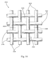
- Figure 14 illustrates a representative broken segment of wire screen 2414 consisting of a number of substantially horizontal, spaced filaments 2416 and a number of substantially vertical, spaced filaments 2418 configured in a basket weave to form an array of openings or interstices 2420 there between. It is contemplated that other weave types or, alternatively, an array of perforations formed in a sheet of conductive material can be employed in practicing the present invention.
- FIG. 15 a representative arrangement of an upper polymer sheet 2422, a lower polymer sheet 2424 and an intermediate sheet of wire screen 2426 juxtaposed as fed into the roller station 2340 of Figure 9 is illustrated.
- the upper and lower polymer sheets 2422 and 2424, respectively are not yet deformed, but may be adhered or bonded to one another by adhesive, welding, plating, coating or the like.
- the roller station 2340 presses the three sheets 2422, 2424 and 2426 together in intimate surface contact as a "sandwich".
- the sheets 2422, 2424 and 2426 may be partially deformed in this step, but retain their distinctive discrete appearance.
- the bladder 2358 applies high downward pressure to the entire exposed surface of the composite as indicated by an arrow 2428.
- the male punch 2386 applies a high, substantially offsetting upward pressure to the entire exposed lower surface of the composite as indicated by an arrow 2430.
- the process affected by the hydroforming station 2342 wherein the substantially discrete layers of the composite feed stock or work piece blank are compressed and reduced into a coalesced composite, is illustrated.
- An important aspect of the hydroforming process is that the individual filaments of the wire screen are reshaped during hydroforming from their original serpentine configuration to their final net form simultaneously as adjacent polymer material flows inwardly, encasing the elements in a unified structure. Because of this phenomena, the individual filaments are supported along their entire length, and are not unduly stressed and do not tend to undesirable localized necking, thinning or rupturing.
- Figure 16 illustrates, in cartoon form, localized flow regions 4232 which extend inwardly from both polymer sheets through adjacent interstices and around the individual strands or filaments composing the wire mesh.
- the discrete generally planer constituent sheets of polymer and conductive materials are locally selectively deformed by the hydroforming process in conformance with the concavities defined by the male punch while avoiding localized thinning or rupturing.
- the flow of the polymer material during the hydroforming process will result in the wire mesh being oriented substantially centrally in the resultant composite structure, with a knit line 2434 between the two polymer sheets being centered with the nominal center plane A - A of the wire mesh 2426.
- material from each of the two sheets of polymer material fully encases at least segments of the individual wire filaments, resulting in an extremely robust composite structure, which in not prone to delaminating.
- the flow of the polymer material during the hydroforming process will result in the wire mesh being oriented closer to the outer surface of the composite structure associated with the thinner polymer sheet. This can position the wire mesh, or a selected portion thereof adjacent a surface of the composite structure or actually exposed through.
Abstract
A housing assembly for a lightweight electronic device for vehicular application is virtually "fastenerless" and includes a one-piece case formed of a layered composite structure including polymer based, electrically insulating sheet material and electrically conductive sheet material that is compression molded or hydroformed to provide three-dimensional case details to accept one or more electronic devices such as circuit boards required for electrical control and display of vehicle based systems. The conductive sheet material is preferably a wire mesh which provides shielding from electrical anomalies and grounding of the circuit boards via exposed wire mesh pads and adjacent ground clips. Major components and subassemblies are self-fixturing during the final assembly process, eliminating the need for dedicated tools, fixtures and assembly equipment.
Description
- The present invention relates generally to apparatus for enclosing electrical subassemblies, and more specifically relates to apparatus for efficiently securing subassemblies to a chassis of an electrical assembly such as an automobile radio, compact disc playing mechanism, cassette tape playing mechanism, navigational aid, personal computer, personal and telematic communication devices or disk drive mechanism.
- Devices such as automobile radios or personal computers contain subassemblies such as cassette playing mechanisms or disk drives that are attached to the chassis using threaded fasteners. The chassis provides structural support for the subassemblies and also provides electromagnetic shielding to limit electromagnetic interference (EMI) experienced by, and/or created by the device. The fasteners ensure that each subassembly within the chassis is properly located and securely retained within the chassis.
- The use of such fasteners can have numerous drawbacks, particularly in a high volume production setting. The process for applying or installing fasteners can vary, but there is usually some degree of automation required, ranging from manually loading a screw into a bit on a pneumatic driver to using self-feeding automated machines. Typically, the torque applied by the device used to drive the fasteners must be monitored regularly and adjusted in order to assure proper seating of the fasteners. When fasteners are used, sheet metal tolerances, as well as tolerances of the fasteners themselves, have to be maintained at tight levels to allow for the minimization of stress in the assembly when aligning multiple fasteners with corresponding holes in the chassis and in the subassembly.
- When threaded fasteners are used to assemble an electrical device, the assembly cycle time can be very long especially in high volume production. An operator assembling the device must typically first obtain the threaded fastener, orient and position it in alignment with the driver bit, then manipulate or actuate the machine to drive the threaded fastener. Furthermore, using threaded fasteners presents a risk of any one of the following upstream failures occurring: stripping of fastener threads; insufficient torque resulting in an unseated fastener; excessive torque resulting in distension/deformation of the fastener or adjacent electrical components; installation of the wrong fastener type or size; foreign object damage due to fasteners and/or metal shavings dropping onto the assembly and/or subassembly; and stripping of the head of the threaded fastener. Also, a fastener installation tool such as a driver and bit can slip off the fastener and impact an electrical component resulting in a damaged assembly.
- If self-tapping fasteners are used, the process of driving the self-tapping fasteners into sheet metal often causes shavings of sheet metal to disperse into the assembly. Such shavings have been known to cause electrical failures, such as shorts or corruption of magnetic components that can permanently damage the product. If self-tapping fasteners are not used, an extra production step is required to pre-form threads in the sheet metal of the chassis and/or the subassembly to be installed within the chassis.
- Fasteners further require an additional inventory burden on the production line in that the production line must be continuously stocked with part numbers (fasteners) other than the integral components that add value to the assembly. Also special tools specifically required for assembly, using fasteners, such as drivers and bits, must be continuously monitored and maintained for proper performance, wear and torque specifications. Typically, the top and/or bottom surface of the chassis must be secured in place after the subassembly is attached to the chassis.
- Special fixtures are often required on the production line to secure a subassembly in a proper location and orientation while it is mounted within the chassis with fasteners. Such fixtures can be very complex, and the use of such fixtures usually requires extra handling of both the subassembly and of the resulting assembly thereby adding to the production cycle time and potentially compromising quality of the final product.
- A radio/CD player 10 of ordinary complexity may require fifty or more threaded fasteners to complete the manufacturing process. Installation of that many fasteners may require that the in-process chassis be re-positioned/re-fixtured ten to fifteen times as it passes along an assembly line of eight to ten skilled workers/work stations.
- Vehicle entertainment systems usually include an audio component such as a radio to enable receiving signals from antennas, contain various forms of playback mechanisms, and have the capacity to accept data from user devices like MP3 players. Typically, the radio has a decorative assembly that provides man-machine interface as well as displaying pertinent data relative to the selected media and audio settings. Also, the back-end or chassis is constructed of metal to provide various functions to ensure the performance of the radio in the vehicular environment. The structure to contain the mass from playbacks, the heat conductive properties, and the electrical shielding and grounding are just a few of the advantages to using the metal construction. Unfortunately, with the density of the metal, the disadvantage of added weight is a side effect of the typical construction. In a vehicle, added weight impacts fuel economy, as well as other hidden costs during assembly that can affect the cost of the product, like sharp edges of metal can be a potential hazard for assemblers in the manufacturing plant as well as added weight can limit the packaging of multiple parts in containers for inter and outer plant distribution.
- Electrical components generate heat in use. The heat must be dissipated away from the electrical components to avoid damage that can be caused by excessive temperatures in the electrical components. For example, excessive temperatures can cause delicate electrical leads to fail or insulating materials to melt, thereby causing a short circuit resulting in damage to, or even failure of, the entire electrical device.
- A convector is often mounted to an outer surface of such a device to dissipate heat generated by components by transferring the heat away from the components and the device to the convector and then to the air through radiation. In order to accomplish this, it is preferable that the convector be physically in contact with the component. The components and the convector can be pressed together to allow even better heat conduction from the components to the convector. Sometimes an intermediary material such as a thermal pad or silicon grease is used between the component and the convector to assist in creating an adequate heat transfer junction.
- Many convectors are made from aluminum due to the high heat conductivity of that material. Convectors often include a plurality of fins to increase the effective surface area of the convector and thereby increase the rate at which the convector can dissipate heat. Typically, aluminum, convectors are formed by an extruding process, during which the fins can also be formed integrally therewith.
- Convectors are usually assembled to the component or components during final assembly of the overall device in which they are used. At final assembly, components such as single inline package (SIP) amplifiers are already soldered into a printed circuit board. The order of assembly can vary as to which component is assembled into the chassis first. The printed circuit board can be installed into the chassis before the convector is mounted to the printed circuit board and the chassis. Alternatively, the convector can be mounted to the chassis before the printed circuit board is mounted to the convector. Sometimes, the convector is assembled to the printed circuit board to form a subassembly before being assembled to the chassis.
- Typically, components are attached to the convector using a clip and one or more threaded fasteners that extend through a hole in the clip and into a hole in the convector. The clip, component and convector must all be simultaneously held in a fixture and then be fastened together with a threaded fastener. If the component includes a hole to accept a threaded fastener, it can be mounted directly to the convector using a threaded fastener that extends through that hole, without using a clip.
- The use of such fasteners can have numerous drawbacks, particularly in a high volume production setting. Often, each hole in the convector that receives a fastener must be separately drilled or punched. This is especially true for an extruded convector if the axis of the hole is not aligned with the direction in which the convector is extruded. The fastening process can vary, but there is usually some degree of automation required, ranging from manually loading a screw into a bit on a pneumatically or electrically powered driver to using self-feeding screw machines. Typically, the torque applied by the device must be monitored regularly and adjusted in order to assure proper seating of the fasteners.
- The clamping force between the convector and the component should be at a proper level to ensure sufficient heat transfer to the convector. When fasteners are used to attach the convector to the component, clamping force is a function of the type of fastener and its condition and degree of assembly (e.g. the level of torque applied during installation of the fastener). Thus, a threaded fastener that is not seated all the way will give less clamping force than one that is seated all the way. Or, a stripped or improper type of fastener may provide an insufficient clamping force.
- Special fixturing is often required to hold a component in the proper location while it is mounted to the convector using one or more fasteners. Such fixturing can be very complex and use of such fixturing usually requires extra handling of both the component and of the resulting assembly, thereby adding to the production cycle time and potentially compromising quality of the final product.
- When threaded fasteners are used, the assembly cycle time can be very long, especially in high volume production. The operator must specifically obtain the threaded fastener, bring it in contact with the driver bit, then drive the threaded fastened. If self-tapping fasteners are used, the process of driving the self-tapping fasteners into metal often causes metal shavings to disperse into the assembly. Such shavings have been known to cause electrical failures that can permanently damage the product. If self-tapping fasteners are not used, an extra production step is necessary to form threads in the metal of the convector.
- Accordingly, there is a need for electrical assemblies that do not require fasteners or tooling for securing a component to a convector.
- Vehicular radio chassis assemblies may typically contain a circuit board assembly and a playback mechanism that may have ground points from the circuit board to the enclosure. They also tend to have heat sinks added for conducting unwanted heat away from the radio circuit board power components to transfer the heat outside of the chassis. When the enclosure has been constructed of a non-metallic material such as plastic, the grounding and shielding has been provided by a variety of methods, including, but not limited to using a metal wire mesh that is insert molded with the structure of the plastic enclosure. Another method may include using localized shields that are assembled and soldered to the circuit board. However, this approach only provides a shield, not a ground. While plastic enclosures are desirable for manufacturing assembly simplification through the elimination of fasteners as well as weight reductions from the metal enclosures, the capitalization to provide a wire mesh insert to a plastic part has been a drawback, especially in low volume applications. Also, the manufacturing process flow has typically coupled the wire mesh insert fabrication cell directly with the plastic molding press, which may not be desired is the molding process utilization is not at a high enough percentage of the available molding press time.
- Static electricity (electrostatics) is created when two objects having unbalanced charges touch one another, causing the unbalanced charge to transfer between the two objects. This phenomenon commonly occurs in homes, vehicles and other environments when the air is dry (i.e. has a characteristic relatively low level of humidity). For instance, when a person slides onto a car seat, electrons may transfer between the two, causing the surface of the person's body to store a charge. When the person, then, touches a vehicle component, the charge may travel (discharge) from the body to the component, thus creating static electricity. If the object touched is an electronic device, such as a home stereo, home theatre system, computer, vehicle entertainment system or other electronic media system, this electrostatic discharge can be harmful to the sensitive electronic components of the device. For instance, when a person slides onto a vehicle seat and inserts a disc into the car stereo, a charge may travel from the body through the disc to the sensitive electronic components in the vehicle stereo. Similar problems may occur when using DVD and other magnetic media and disc players.
- Accordingly, problems with the drainage of a static electric charge impacting sensitive electronic components continue to persist.
- The present invention provides numerous product and process advantages which collectively result in substantial cost and labor savings. By way of example, the preferred design optimizes the assembly process. It minimizes the required handling of major components and subassemblies during the assembly cycle. Final assembly is optimized, wherein only three major components and subassemblies are involved. This minimizes the number of work stations and fixtures, in-process transfers between work stations and total assembly cycle time. The inventive design permits selection of the optimal mechanical product configuration for a given receiver family. Furthermore, it permits idealized electrical and mechanical building block partitioning for common and unique elements.
- The preferred embodiment of the invention contemplates screwless final assembly without the use of tools, fixtures and assembly machines. This greatly enhances in-process product flow in the factory, improves scheduling of final assembly, and allows labor intensive processes such as stick lead assembly to be largely moved off-line. This greatly reduces both direct and indirect labor requirements. Furthermore, inventory control is simplified inasmuch as position part proliferation is deferred to or near the end of process.
- The preferred embodiment of the invention provides an electronic system housing assembly and method which includes a compression molded three-dimensional case configured to define a substantially closed cavity, either in its own right, or in combination with a front closure member. The case is formed of layered coalesced composite of one or more layers of relatively rigid polymer sheet material and a layer of electrically conductive sheet material operative to shield an electronic component within the cavity and to mount the housing assembly within a host vehicle.
- The automotive electronic system housing assembly comprises a compression molded three-dimensional case configured to define a substantially closed cavity. Said case is formed of a layered coalesced composite of relatively rigid polymer sheet material and electrically conductive sheet material. The case is operative to shield an electronic component carried within said cavity from electrical anomalies. The case defines integral engagement features operative to mount said electronic component within said cavity and to mount said housing assembly within a host automobile.
- The case may include upper and lower cooperating case halves integrally interconnected along a common edge thereof by a living hinge. The case is formed of a layered coalesced composite of relatively rigid continuous polymer sheet material and electrically conductive sheet material. The material is operative to shield an electronic component carried within a closed cavity formed thereby from electrical anomalies. The case defines integral engagement features operative to mount said electronic component within the cavity and to mount the housing assembly within a host automobile.
- Also, the electrically conductive material comprises a wire screen. The coalescence is affected by polymer material from the polymer sheet material flowing under compression loading within interstices of the wire screen.
- The living hinge comprises a continuous portion of the layer of electrically conductive material integrally bridging the adjacent case half edges.
- The living hinge comprises a segment of said layer of polymer material integrally bridging said adjacent case half edges.
- The case is formed of a layered coalesced composite of inner and outer layers of continuous polymer sheet material and an intermediate layer of electrically conductive sheet material.
- The electrically conductive material comprises a wire screen and wherein the inner and outer layers of polymer sheet material flow under compressive loading within the interstices of the wire screen to form a knit line substantially collocated on a center line of said wire screen.
- A localized portion of the conductive material is exposed within the cavity to affect an electrical ground path to the electronic component.
- Also, a localized portion of said conductive material is exposed on an external surface of said case to affect an electrical ground path to the host automobile.
- The housing further comprises a discrete closure member cooperating with the case to enclose the electronic component. The closure member forms of rigid electrically conductive material or a layered coalesced composite of relatively rigid continuous polymer sheet material and electrically conductive sheet material.
- The closure member comprises a trim panel integrating operator controls and displays carried adjacent an outer surface of said closure member. The trim panel conductive sheet material is in circuit with said case conductive sheet material. The trim panel defines integral features configured to cooperatively engage mating case engagement features to affect fastenerless interconnection of said housing assembly and said trim panel.
- The housing assembly further comprises a convector for dissipating heat generated by a power device incorporated with the electronic component. The convector is mounted externally on the case and it defines integral engagement features to affect fastenerless interconnection of the housing assembly and the convector.
- The upper case half defines a top wall, left and right partial upper side walls.An upper partial rear wall, and wherein said lower case half defines a bottom wall, left and right partial lower side walls, and a lower partial rear wall. The case defines a front opening when said upper and lower case halves are in a folded orientation.
- The invention is also about a method of fabricating an automotive electronic system housing assembly including a contoured case and at least one discrete closure member cooperatively enclosing at least one electronic component. The method comprises the steps of:
- forming a generally planer composite preform blank consisting of at least one layer of relatively rigid polymer sheet material and at least one layer of electrically conductive sheet material capable of shielding said electronic component from electrical anomalies;
- positioning said preform blank within a compression mold apparatus wherein said blank registers with a contoured die form within said apparatus;
- actuating said compression mold apparatus, whereby areas of said preform blank are selectively distended to substantially conform to said contoured die to form said case to net shape; and
- releasing and removing said case from said apparatus, trimming and/or punching said case to final net shape.
- pre-heating said perform blank prior to positioning it within said compression mold apparatus,
- providing said polymer sheet material and said electrically conductive sheet material from a continuous source of feed stock.
- The compression mold apparatus comprises a hydroform mold that includes means to controllably the position of the die form adjacent one surface of the preform blank, and flexible, fluid-filled bladder means operable to apply opposed surface pressure against an opposite surface of the preform blank to affect the distension as a function of fluid pressure within the bladder and displacement of the die form.
- The case is formed into upper and lower case halves integrally joined by an elongated living hinge.
- The step of forming the composite preform blank consists of forming a blank consisting of upper and lower layers of relatively rigid polymer sheet material and an intermediate layer of electrically conductive sheet material capable of shielding said electronic component from electrical anomalies.
- The method further comprises the steps of:
- affixing the electrical component to one of the case halves;
- folding the preform wall case halves about the living hinge until the electrical component is substantially enclosed by the case halves; and;
- affixing respective pairs of cooperating engagement features integrally formed on the case halves to retain said case in a three-dimensional configuration,
- affixing the closure member to the case to effect substantially complete enclosure of the electronic device.
- The present invention will now be described, by way of example, with reference to the accompanying drawings, in which:
-
FIG. 1 , is an exploded, perspective view of the cockpit area of an automobile, illustrating an instrument panel mounted electronic system embodying the present invention; -
FIG. 2 , is a perspective view of the inside details of a compression molded clamshell-shaped case of the electronic system ofFigure 1 , including upper and lower case halves joined by a living hinge in an as-molded configuration; -
FIG. 3 , is an exploded, perspective view of the clamshell case ofFigure 2 aligned for assembly with an electronic circuit assembly; -
FIG. 4 , is a perspective view of the exploded assembly ofFigure 3 with the upper and lower case halves folded about the living hinge to define a cavity enclosing the electronic circuit assembly; -
FIG 5 is an exploded, perspective view of the folded case assembly ofFigure 4 aligned for assembly with a vehicle operator accessible trim panel; -
FIG. 6 , is a top plan view of the electronic system ofFigure 4 ; -
FIG. 7 , is a cross-sectional view of the electronic system taken along lines 7-7 ofFigure 6 ; -
FIG. 8 is a broken segment of a portion of the cross-sectional view ofFigure 7 on an enlarged scale, illustrating details of the mounting of the electronic circuit assembly within the housing case between two opposed locating pedestals; -
FIG. 9 , is a schematic representation of manufacturing process equipment for producing a continuous strip of composite/laminate (plastic/screen/plastic) material for subsequent compression molding via hydorform technique for formation of a case structure of the electronic system ofFigure 1 ; -
FIG. 10 , is a cross-sectional view of a hydroform die employed in the manufacturing process ofFigure 9 , including an upper portion including a draw ring and a fluid filled flexible bladder, a lower portion guiding a displaceable male punch die, and an intermediate work piece; -
FIG. 11 , is a cross-sectional view of the hydroform die ofFigure 10 , wherein the upper and lower portions have been closed to clampingly engage the work piece and the flexible bladder has been pressurized to press the work piece against the male punch die to partially deform the work piece against the male punch die; -
FIG. 12 , is a cross-sectional view of the hydroform die ofFigure 10 , wherein the upper and lower portions remain in the closed position and the male punch die is hydraulically displaced upwardly to fully deform the work piece to mimic the contours of the male punch die; -
FIG. 13 , is a cross-sectional view of the hydroform die wherein the fluid pressure in the bladder has been released, the male punch die is retracted to its released position, and the upper and lower portions are spaced to release the fully shaped work piece; -
FIG. 14 , is a broken segment of sheet wire mesh, on an enlarged scale, of the type continuously deployed from a center feed roller offigure 9 ; -
FIG. 15 , is a broken segment of feed material including the wire mesh ofFigure 14 arranged with upper and lower layers of polymer sheet material prior to hydroforming; and -
FIG. 16 , is a broken segment of post-hydroforming coalesced composite material wherein localized portions of the upper and lower polymer sheet material flows inwardly within wire mesh interstices to mechanically couple therewith, forming a knit line nominally coincident the center line of the adjacent wire mesh. - Although the drawings represent varied embodiments and features of the present invention, the drawings are not necessarily to scale and certain features may be exaggerated in order to illustrate and explain the present invention. The exemplification set forth herein illustrates several aspects of the invention, in one form, and such exemplification is not to be construed as limiting the scope of the invention in any manner.
- Referring to
Figure 1 , an electronicsystem housing assembly 2200, embodied in one application as an automotive audio system, is illustrated in assembly within acentral opening 2202 formed in aninstrument panel 2204 of a host automobile. Thehousing assembly 2200 includes a three-dimensional case 2206 cooperating with an operatoraccessible trim panel 2208. As will be described in greater detail herein, thecase 2206 andtrim panel 2208 and/or a discrete closure member cooperate to define a substantially closed cavity for carrying at least one electronic component such as a radio circuit assembly. - Although primarily intended for application in automotive audio systems, the present invention can also be employed in packaging navigation, object detection, telematics, system controllers, power supplies and other systems including electronic devices requiring shielding from electronic anomalies.
- In the illustrative embodiment of the invention, the
instrument panel opening 2202 is located conveniently adjacent a designated operator seating position whereby input/output devices and displays of theaudio system 2200 installed therein are easily accessible. Thecase 2206 includes left and right longitudinally extendingguides instrument panel opening 2202 is configured to nestingly receive theaudio assembly 2200 which is front-loaded therein. Theinstrument panel opening 2202 defines left andright sidewalls 2214 which include opposed, cooperating longitudinally extendingguideways 2216 configured to slidingly receive the audio system guides 2212 and 2214. Eachcase guide notch 2218 therein including a rearwardly facingstop surface 2220.Guideways 2216 form anintegral catch 2222 which, upon installation of theaudio system 2200, self-engages acorresponding stop surface 2220 to secure the front surface of thetrim panel 2208 with the adjacent portion of theinstrument panel 2204 without the need for separate fasteners. Referring toFigure 2 ,case 2206 is illustrated in its "as formed" configuration illustrating the internal details thereof. As described herein,case 2206 is compression molded by hydroforming process forming a layered coalesced composite of inner and outer discrete layers of relatively rigid polymer sheet material enclosing an intermediate discrete layer of electrically conductive sheet material, preferably wire screen. The sheets of polymer and conductive material are continuously fed in parallel alignment into the hydroforming press which serially forms three-dimensional case blanks, which are trimmed and punched to final net form either during the hydroforming process or thereafter as a separate process step. - In the preferred embodiment,
case 2206 is formed in a unitary clamshell configuration including a first orupper case half 2224 and a second orlower case half 2226 integrally interconnected along a common edge by aliving hinge 2228. The case halves 2224 and 2226 are substantially mirror-images of one another and configured to be manually folded about common edge axis X - X from the initial open position ofFigure 2 to the closed orientation ofFigure 4 during the final assembly process. Details of thecase 2206 are described herein below as if thecase 2206 is in the folded orientation as illustrated inFigure 4 . - The
upper case half 2224 defines atop wall 2230, left and right upperpartial side walls rear wall 2236. The lowermost edges of the left and right upperpartial side walls integral flanges rear wall 2236 transitions into a rearwardly extendingintegral flange 2242.Flanges upper case half 2224 to provide a seat surface with thelower case half 2226 and to rigidify the overall structure of thehousing assembly 2200. A laterally inwardly transitingnotch edge 2244 terminating in astop surface 2246 is formed in the outer portion of theflange 2238. Likewise, a laterally inwardly transitingnotch edge 2248 terminating in astop surface 2250 is formed in the outer portion of theflange 2240. - The
top wall 2230 of theupper case half 2224 integrally forms two resilient,bifurcated engagement tabs 2252 extending forwardly from theleading edge 2253 thereof for mounting thecase 2206 to thetrim panel 2208. A first, generallyrectangular opening 2254 extends through a portion of the upper partialrear wall 2236 and theadjacent flange 2242. A second,semi-circular opening 2256 extends through a portion of the upper partialrear wall 2236 and theadjacent flange 2242. A pair of spaced-apartpedestals 2258 is integrally formed in thetop wall 2230 and extend downwardly, terminating on a mountingsurface 2260. - The
lower case half 2226 defines abottom wall 2262, left and right lowerpartial side walls partial side walls integral flanges 2270 and 2272, respectively, and the uppermost most edge of the lower partial rear wall 2268 transitions into a rearwardly extendingintegral flange 2274.Flanges lower case half 2226 to provide a seat surface with theupper case half 2224 and to rigidify the overall structure of thehousing assembly 2200. A laterally inwardly transitingnotch edge 2276 terminating in astop surface 2278 is formed in the outer portion of the flange 2270. Likewise, a laterally inwardly transitingnotch edge 2280 terminating in astop surface 2282 is formed in the outer portion of theflange 2272. - The
bottom wall 2262 of thelower case half 2226 integrally forms two resilient,bifurcated engagement tabs 2284 extending forwardly from theleading edge 2285 thereof for mounting thecase 2206 to thetrim panel 2208. A first, generallyrectangular opening 2286 extends through a portion of the lower partial rear wall 2268 and theadjacent flange 2274. A second,semi-circular opening 2288 extends through a portion of the lower partial rear wall 2268 and theadjacent flange 2274.Rectangular openings case 2206. Likewise,semi-circular openings case 2206. A pair of spaced-apartpedestals 2294 are integrally formed in thebottom wall 2262 and extend upwardly, terminating in a mountingsurface 2296. Ashort locating boss 2298 extends above the mountingsurface 2296. A patch ofwire screen 2300 is exposed on one or more of the mountingsurfaces case 2206. - Referring to
Figure 3 , an electronic component configured to be carried within a cavity defined by thecase 2206. Anelectronic circuit assembly 2302 consists of a generally planer substrate orcircuit board 2304 configured to carryprocessors 2306,integrated circuits 2307,discrete components 2308, aheat sink 2309 and interconnecting circuit traces. As best seen inFigure 7 , circuit components can be mounted on both sides of thecircuit board 2304. Amulti-circuit connector 2310 is mounted on aleading edge 2312 of thecircuit board 2304 for interfacing with thetrim panel 2208. A multi-circuit power andoutput connector 2312 and anantenna feed connector 2314 are mounted on atrailing edge 2316 of thecircuit board 2304 for interfacing with the host vehicle wire harness and antenna cable. Thecircuit board 2304 has a pair of spaced-apart mountingholes 2318 positioned to register with their respective mounting pedestals 2294.Ground pads 2320 are formed on one or both sides of thecircuit board 2304 concentric with their respective mounting holes 2318. - The
case 2206 is assembled by placing it on a generally flat work surface with the internal surfaces of the case halves 2224 and 2226 facing upwards. Theelectronic circuit assembly 2302 is installed by manually aligning it within one of the case halves 2224/2226. In so doing, the power/input connector 2312 is nestingly received within therectangular opening 2286 and theantenna feed connector 2314 is nestingly received within thesemi-circular opening 2288 of thelower case half 2226. Simultaneously, thepedestals 2294 register with their respective mountingholes 2318 with the locatingboss 2298 extending there through. When placed in the assembled position, the mountingsurface 2296 of eachpedestal 2294 retains theelectronic circuit assembly 2302 in a spaced relation above the inner surface of thelower case half 2226 and the exposed wire screen patch electrically contacts theadjacent ground pad 2320. - Referring to
Figure 4 , after installation of theelectronic circuit assembly 2302 on thelower case half 2226, theupper case half 2224 is manually folded about 180° counterclockwise from the position illustrated inFigure 3 about livinghinge 2228 axis X - X to assume its assembled (closed) position illustrated inFigure 4 . The subassembly of thecase 2206 with theelectronic circuit assembly 2302 is completed by the installation of fasteners such asscrews 2322 throughholes 2261 inupper pedestals 2258, and through mountingholes 2318 in thecircuit board 2304, threadably into correspondingholes 2299 inpedestals 2294. - When in the closed position, the
flanges upper case half 2224abut flanges lower case half 2226 to assure a rigid structure ofcase 2206. In so doing,openings output connector 2312 andantenna feed connector 2314 in their installed positions. Furthermore, when in the closed position, notchededge 2276 and stopsurface 2278 of flange 2270 register with notchededge 2244 and stopsurface 2246 offlange 2238 to define left-hand notch 2218 and stopsurface 2220 ofFigure 1 . Similarly, when in the closed position, notchededge 2280 and stopsurface 2282 offlange 2272 register with notchededge 2248 and stopsurface 2250 offlange 2240 to define right-hand notch 2218 and stopsurface 2220 ofFigure 1 . - As illustrated in
Figure 4 , the clamshell-type case 2206 forms a three-dimensional configuration defining a substantially closedcavity 2324 which, in application shields theelectronic circuit assembly 2302 from electrical anomalies as described herein above. It is contemplated that the case can be configured to fully enclose theelectronic circuit assembly 2302 by the addition of integral front wall portions, or alternatively, to enclose theelectronic circuit assembly 2302 in combination with a discrete metal or composite front closure member or, preferably, by mounting thecase 2206 directly to the read surface of thetrim panel 2208 as illustrated inFigure 5 . - Referring to
Figure 5 , final assembly of the electronicsystem housing assembly 2200 is affected by manual mating engagement of the case 2200 -electronic circuit 2302 subassembly with the operatoraccessible trim panel 2208. Thetrim panel 2208 is constructed substantially as described herein above, with the exception that a rearsurface closure member 2326 protectively encloses internal components of thetrim panel 2208. Theclosure member 2326 has an array ofslot openings 2328 arranged to register withengagement tabs 2252 extending forwardly from thecase 2206. Amulti-circuit plug 2330 extends through theclosure member 2326 to matingly engage the circuitboard connector assembly 2310 to complete the electrical interface between theelectronic circuit assembly 2302 and the trim panel circuitry. During final assembly, eachengagement tab 2252 registers with and engages an associatedslot opening 2328. Accordingly, no separate fasteners are required. If desired, thescrews 2322 ofFigure 4 can be replaced by appropriate self-engaging features formed with the case halves 2224 and 2226. - Referring to
Figures 6 ,7 and 8 , details of the fully assembled electronicsystem housing assembly 2200 are illustrated. When fully assembled, theelectronic circuit assembly 2302 is supported at two locations between cooperatingpedestals rear case wall 2236 and 2268 via (1.) power output/connector 2314 extending throughrectangular opening antenna feed connector 2314 extending throughcircular opening electronic circuit assembly 2302 is generally centered vertically within thecavity 3324 formed by thecase 2206 with components carried on both the upper and lower surfaces of thecircuit board 2304. It is contemplated that other features for positioning, locating, spacing, and/or isolating theelectronic circuit assembly 2302 as well as other components disposed within thecase 2206 or externally thereof can be integrally formed in as part of the hydroforming process. For example, a heat sink can be mounted externally of the case via integral retention features such as described earlier herein with the addition of a window in thecase 2206 for routing a thermal interconnection with a power device disposed within thecase 2206. - Referring to
Figure 9 , a hydroforming process for producing composite material is illustrated, including drawing polymeric sheet material off upper and lowercontinuous rolls third roll 2336. The three discrete sheets are heated atstation 2338, rolled together atstation 2340, hydroformed atstation 2342, cut-off or die cut, scribed, punched and treated at astation 2344, and, finally, assembled at aworkstation 2346. - Referring to
Figures 10 - 13 , details and operation of thehydroform station 2342 are illustrated. Thehydroform station 2342 includes anupper die portion 2346 and alower die portion 2348. Theupper die portion 2346 includes atop wall 2350 and downwardly extendingperipheral side walls 2352 defining adownwardly opening cavity 2354 and which serves as a draw ring and an upperblank holder 2356. A closedflexible bladder 2358 occupies the entire volume of thecavity 2354. Thebladder 2358 is entirely filled with a substantially incompressible liquid such ashydraulic fluid 2360. In operation, the exposed,lower wall 2362 of thebladder 2358 acts upon the upper surface of a work piece blank 2364 disposed immediately there below. - The
hydraulic fluid 2360 in thebladder 2358 is selectively pressurized/de-pressurized from areservoir 2366 fluidly coupled with thebladder 2358 via a sealedfeed line 2368. Apiston 2370 is displaceable within thereservoir 2366 to effect the controlled pressurization/de-pressurization of thebladder 2358 in response to acontrol valve 2374 fed by apressure source 2372. Apressure sensor 2376 communicating with thebladder 2358 operates to sense and display the instantaneous pressure therein and provide a feedback signal to the control valve. - The
lower die portion 2348 includes abottom wall 2378 and upwardly extendingperipheral side walls 2380 defining anupwardly opening cavity 2382 and serves as a lowerblank holder 2384. Amale punch 2386 is disposed within saidwalls 2380 and is displaceable upwardly/downwardly. Theupper surface 2388 of themale punch 2386 forms fixed contours and concavities which substantially mimic the basic "as molded" shape of thecase 2206 ofFigures 1 - 7 . In the released position illustrated inFigure 10 , themale punch 2386 is in its fully-retracted, downward most position, with thebottom surface 2390 of themale punch 2386 in close proximity withbottom wall 2378. The variable volume extending between thebottom surface 2390 of themale punch 2386 and theinner bottom wall 2378 of thelower die portion 2348 defines a sealedcavity 2392.Cavity 2392 is filled with an incompressible liquid such as hydraulic fluid which is selectively pressurized/de-pressurized from apressurized reservoir feed 2394 through acontrol valve 2396 interconnected withcavity 2392 through a sealedfeed line 2398.Suitable controllers hydroforming station 2342. - Referring to
Figures 9 and10 , feedstock for thehydroform station 2342 consists of a continuousupper sheet 2404 of relatively rigid polymer material fromupper roll 2332, a continuouslower sheet 2406 of relatively rigid polymer material fromlower roll 2334, and a continuousintermediate sheet 2408 of conductive material (preferably perforated sheet or wire screen) frommiddle roll 2336. The three sheets are heated and rolled together atstation 2340, forming a continuous sheet of at least partially coalesced composite, which enters thehydroforming station 2342 either as a continuous sheet or as work piece blank 2364. Although cutting, punching and trimming process steps are illustrated as taking place in a subsequent process step atstation 2344, they can be implemented within thehydroforming station 2342 whereby, the continuous composite sheet material can be formed to net or final shape in thehydroform station 2342. - Referring to
Figure 10 , thehydroforming station 2342 is illustrated at the beginning or first step of a cycle of operation. As illustrated, the fluid in both the upper and lower dieportions bladder 2358 is fully drawn upwardly into thecavity 2354 of theupper die portion 2346 and themale punch 2386 is fully drawn downwardly into thecavity 2382 of thelower die portion 2348. As indicated byarrow 2410, the upper and lower dieportions blank holders - Referring to
Figure 11 , thehydroforming station 2342 is illustrated at the second step of a cycle of operation. As illustrated, the work piece blank 2364 has been registered with the upper and lowerblank holders portions bladder 2358 in theupper die portion 2346 has been pressurized; whereby thelower bladder wall 2362 is distended downwardly at least partially into thecavity 2382 of the lower die portion 3248. In so doing, thelower bladder wall 2362 displaces the exposed portion of thework piece 2364 downwardly into at least partial engagement and conformance with theupper surface 2388 of themale punch 2386. This is accomplished by openingvalve 2374 to drivepiston 2370 to its downward most limit of travel, thereby injecting additional fluid into thebladder 2358. As indicated by thepressure sensor 2376, the pressure within thebladder 2358 has increased sufficiently to at least partially deform thework piece 2364. - Referring to
Figure 12 , thehydroforming station 2342 is illustrated at the third step of a cycle of operation. As illustrated, thebladder 2358 remains fully charged with fluid and, simultaneously,control valve 2396 is opened bycontroller 2402, diverting pressurized fluid into sealedcavity 2392 throughfeed line 2398. Ascavity 2392 fills, themale punch 2386 is forcefully displaced upwardly against the exposed lower surface of the work piece blank 2364 until the offsetting downward force applied by the fluid-filled bladder applies an offsetting force. Insodoing, thelower bladder wall 2362 displaces the exposed portion of thework piece 2364 downwardly into complete engagement and conformance with theupper surface 2388 of themale punch 2386. As indicated by thepressure sensor 2376, the pressure within thebladder 2358 has increased sufficiently to fully deform thework piece 2364 into its final net shape. - Referring to
Figure 13 , thehydroforming station 2342 is illustrated at the fourth step of a cycle of operation. As illustrated, the sealedcavity 2392 in thelower die portion 2348 has been drained, lowering themale punch 2386 back to its retracted position illustrated inFigure 10 . Simultaneously, thebladder 2358 has been partially drained with the fluid flowing back into thereservoir 2366, driving thepiston 2370 back to its original position illustrated inFigure 10 . As indicated by thepressure sensor 2376, the pressure within thebladder 2358 has returned to its initial released value. Finally, the upper and lower dieportions composite case 2412. Subsequently, the compression moldedhydroformed case 2412 is horizontally removed from thehydroforming station 2342 and transferred to the trim-punch station 2344 (if required), and ultimately to thefinal assembly station 2346. - Referring to
Figures 14 - 16 , the coalescence process that takes place in the work piece blank 2346 during the process steps ofFigures 10 - 13 is illustrated.Figure 14 illustrates a representative broken segment ofwire screen 2414 consisting of a number of substantially horizontal, spacedfilaments 2416 and a number of substantially vertical, spacedfilaments 2418 configured in a basket weave to form an array of openings orinterstices 2420 there between. It is contemplated that other weave types or, alternatively, an array of perforations formed in a sheet of conductive material can be employed in practicing the present invention. - Referring to
Figure 15 , a representative arrangement of anupper polymer sheet 2422, alower polymer sheet 2424 and an intermediate sheet ofwire screen 2426 juxtaposed as fed into theroller station 2340 ofFigure 9 is illustrated. As illustrated, the upper andlower polymer sheets roller station 2340 presses the threesheets sheets Figures 11 and12 ) thebladder 2358 applies high downward pressure to the entire exposed surface of the composite as indicated by anarrow 2428. Simultaneously or subsequently, themale punch 2386 applies a high, substantially offsetting upward pressure to the entire exposed lower surface of the composite as indicated by anarrow 2430. - Referring to
Figure 16 , the process affected by thehydroforming station 2342, wherein the substantially discrete layers of the composite feed stock or work piece blank are compressed and reduced into a coalesced composite, is illustrated. An important aspect of the hydroforming process is that the individual filaments of the wire screen are reshaped during hydroforming from their original serpentine configuration to their final net form simultaneously as adjacent polymer material flows inwardly, encasing the elements in a unified structure. Because of this phenomena, the individual filaments are supported along their entire length, and are not unduly stressed and do not tend to undesirable localized necking, thinning or rupturing.Figure 16 illustrates, in cartoon form, localized flow regions 4232 which extend inwardly from both polymer sheets through adjacent interstices and around the individual strands or filaments composing the wire mesh. Taking a macroscopic view, the discrete generally planer constituent sheets of polymer and conductive materials are locally selectively deformed by the hydroforming process in conformance with the concavities defined by the male punch while avoiding localized thinning or rupturing. - When inner and outer polymer sheets of nearly equal thickness are employed, the flow of the polymer material during the hydroforming process will result in the wire mesh being oriented substantially centrally in the resultant composite structure, with a
knit line 2434 between the two polymer sheets being centered with the nominal center plane A - A of thewire mesh 2426. In this condition, material from each of the two sheets of polymer material fully encases at least segments of the individual wire filaments, resulting in an extremely robust composite structure, which in not prone to delaminating. Alternatively, with inner and outer polymer sheets of differing thickness, the flow of the polymer material during the hydroforming process will result in the wire mesh being oriented closer to the outer surface of the composite structure associated with the thinner polymer sheet. This can position the wire mesh, or a selected portion thereof adjacent a surface of the composite structure or actually exposed through. - It is to be understood that the invention has been described with reference to specific embodiments and variations to provide the features and advantages previously described and that the embodiments are susceptible of modification as will be apparent to those skilled in the art.
Claims (15)
- An automotive electronic system housing assembly (2200 comprising:a compression molded three-dimensional case (2206) configured to define a substantially closed cavity (2324), said case (2206) formed of a layered coalesced composite of polymer sheet material and electrically conductive sheet material operative to shield an electronic component (2302) carried within said cavity (2324) from electrical anomalies, said case (2206) defining integral engagement features (2294, 2298, 2216) operative to mount said electronic component (2302) within said cavity (2324) and to mount said housing assembly (2200) within a host automobile.
- An automotive electronic system housing assembly (2200) as set in claim 1 wherein the case (2206) is
a clamshell-shaped case (2206) including upper (2224) and lower (2226) cooperating case halves integrally interconnected along a common edge thereof by a living hinge (2228). - The housing assembly (2200) as set in any of the preceding claim, wherein said electrically conductive material comprises a wire screen (2300).
- The housing assembly (2200) of claim 3, wherein said coalescence is affected by polymer material from said polymer sheet material flowing under compression loading within interstices of said wire screen (2300).
- The housing assembly (2200) of claim 2, wherein said living hinge (2228) comprises a continuous portion of said layer of electrically conductive material integrally bridging said adjacent case half edges (2224, 2226).
- The housing assembly (2200) of claim 2, wherein said living hinge (2228) comprises a segment of said layer of polymer material integrally bridging said adjacent case half edges (2224, 2226).
- The housing assembly (2200) as set in any of the preceding claim, wherein a localized portion of said conductive material is exposed within said cavity to affect an electrical ground path (2320) to said electronic component (2302).
- The housing assembly (2200) as set in any of the preceding claim, wherein a localized portion of said conductive material is exposed on an external surface of said case (2206) to affect an electrical ground path to said host automobile.
- The housing assembly (2200) as set in any of the preceding claim, further comprising a discrete closure member (2326) cooperating with said case (2206) to enclose said electronic component (2306), said closure member formed of rigid electrically conductive material or a layered coalesced composite of continuous polymer sheet material and electrically conductive sheet material.
- The housing assembly (2200) of claim 9, wherein said closure member (2326) comprises a trim panel (2208) integrating operator controls and displays carried adjacent an outer surface of said closure member (2326), wherein said trim panel (2208) conductive sheet material is in circuit with said case conductive sheet material.
- The housing assembly (2200) of claim 10, wherein said trim panel (2208) defines integral features (2328) configured to cooperatively engage mating case engagement features (2252) to affect fastenerless interconnection of said housing assembly (2200) and said trim panel (2208).
- The housing assembly (2200) of claim 2, further comprising a convector for dissipating heat generated by a power device incorporated with said electronic component (2302), said convector mounted externally on said case and defining integral engagement features to affect fastenerless interconnection of said housing assembly and convector.
- The housing assembly (2200) of claim 2, wherein upper case half (2224) defines a top wall, left and right partial upper side walls, and an upper partial rear wall, and wherein said lower case half (2226) defines a bottom wall, left and right partial lower side walls, and a lower partial rear wall, and wherein said case (2206) defines a front opening when said upper (2224) and lower (2226) case halves are in a folded orientation.
- A method of fabricating an automotive electronic system housing assembly (2200) including a contoured case and at least one discrete closure member cooperatively enclosing at least one electronic component (2306), said method comprising the steps of:forming a generally planer composite preform blank (2364) consisting of at least one layer of polymer sheet material and at least one layer of electrically conductive sheet material capable of shielding said electronic component (2306) from electrical anomalies;positioning said preform blank (2364) within a compression mold apparatus (2342) wherein said blank r(2364) egisters with a contoured die form within said apparatus;actuating said compression mold apparatus (2342), whereby areas of said preform blank (2364) are selectively distended to substantially conform to said contoured die to form said case (2206) to net shape; andreleasing and removing said case (2206) from said apparatus (2342).
- The method of claim 16, wherein said compression mold apparatus (2342) comprises a hydroform mold including means to controllably position said die form adjacent one surface of said preform blank (2364), and flexible, fluid-filled bladder means operable to apply opposed surface pressure against an opposite surface of said preform blank (2364) to affect said distension as a function of fluid pressure within said bladder and displacement of said die form.
Applications Claiming Priority (1)
| Application Number | Priority Date | Filing Date | Title |
|---|---|---|---|
| US12/787,452 US8305773B2 (en) | 2006-08-18 | 2010-05-26 | Lightweight audio system for automotive applications and method |
Publications (1)
| Publication Number | Publication Date |
|---|---|
| EP2391199A1 true EP2391199A1 (en) | 2011-11-30 |
Family
ID=44117453
Family Applications (1)
| Application Number | Title | Priority Date | Filing Date |
|---|---|---|---|
| EP20110161742 Withdrawn EP2391199A1 (en) | 2010-05-26 | 2011-04-08 | Lightweight audio system for automotive applications and method |
Country Status (3)
| Country | Link |
|---|---|
| US (2) | US8305773B2 (en) |
| EP (1) | EP2391199A1 (en) |
| CN (1) | CN102355612A (en) |
Families Citing this family (23)
| Publication number | Priority date | Publication date | Assignee | Title |
|---|---|---|---|---|
| US7044546B2 (en) | 2002-08-14 | 2006-05-16 | Johnson Safety, Inc. | Headrest-mounted monitor |
| US7762627B2 (en) | 2005-11-02 | 2010-07-27 | Chung Lung Chang | Headrest-mounted entertainment systems |
| US20070101372A1 (en) * | 2005-11-02 | 2007-05-03 | Chang Chung L | Headrest mounted entertainment system |
| US8388060B2 (en) | 2007-04-16 | 2013-03-05 | Chung Lung Chang | Headrest-mounted entertainment systems |
| US8162368B2 (en) * | 2008-10-10 | 2012-04-24 | Carnevali Jeffrey D | Vehicle console having molded end parts |
| US20100282802A1 (en) * | 2009-05-07 | 2010-11-11 | Carnevali Jeffrey D | Flashlight holder mounted in a vehicle console |
| US20100284199A1 (en) * | 2009-05-07 | 2010-11-11 | Carnevali Jeffrey D | Flashlight holder mountable in a vehicle |
| US8111510B2 (en) * | 2010-04-19 | 2012-02-07 | Yuemin Dong | Flip-out multimedia car stereo |
| US8287285B2 (en) * | 2010-10-22 | 2012-10-16 | Johnson Controls Technology Company | System and method for reducing electromagnetic interference from a conductive interior trim component |
| WO2012125436A1 (en) | 2011-03-11 | 2012-09-20 | Delphi Technologies, Inc. | Flexible electronic circuit enclosure assembly |
| DE102012207599B4 (en) * | 2012-05-08 | 2022-03-17 | Vitesco Technologies GmbH | Control unit, in particular for a motor vehicle |
| US9456535B2 (en) | 2012-12-27 | 2016-09-27 | Steven L. Harrington | Retrofit automobile radio |
| US10201105B2 (en) | 2015-06-22 | 2019-02-05 | Apple Inc. | Combination injection molding and hydroforming |
| FR3050967B1 (en) * | 2016-05-04 | 2018-04-27 | Peugeot Citroen Automobiles Sa | INSERT FOR DASHBOARD OF MOTOR VEHICLE |
| CN107135627B (en) * | 2017-06-20 | 2020-01-17 | 惠州华阳通用电子有限公司 | Automobile sound equipment navigation host and automatic assembly method thereof |
| CN107295438A (en) * | 2017-07-04 | 2017-10-24 | 惠州市其正科技有限公司 | A kind of legerity type Multifunctional portable stereo system |
| CN107685697A (en) * | 2017-07-26 | 2018-02-13 | 东莞市天逸电子有限公司 | A kind of modified form vehicle speaker and assembly method |
| CN109638539B (en) * | 2018-12-10 | 2024-03-26 | 深圳市搏鑫科技有限公司 | Electric connecting device |
| DE112020004352T5 (en) * | 2019-09-12 | 2022-06-09 | Denso Corporation | In-vehicle electronic device |
| US11372458B2 (en) * | 2020-03-12 | 2022-06-28 | Adlink Technology Inc. | Structure of case assembly |
| CN111736656B (en) * | 2020-06-11 | 2022-03-15 | 张善龙 | Electronic resident identity card |
| EP3962243A1 (en) * | 2020-09-01 | 2022-03-02 | Rohde & Schwarz GmbH & Co. KG | Circuit board, control unit, electronic device, and method of assembling an electronic device |
| CN117440617A (en) | 2022-07-12 | 2024-01-23 | 通用汽车环球科技运作有限责任公司 | Enhanced integration of power inverter using polymer composite encapsulation |
Citations (4)
| Publication number | Priority date | Publication date | Assignee | Title |
|---|---|---|---|---|
| US5566055A (en) * | 1995-03-03 | 1996-10-15 | Parker-Hannifin Corporation | Shieled enclosure for electronics |
| DE10027079A1 (en) * | 2000-05-31 | 2001-12-06 | Konrad Schnupp | Re-shaping a plate-shaped workpiece involves applying pneumatic pressure to pre-deform one side of workpiece, then re-shaping workpiece mechanically and/or hydro-mechanically |
| US20080049949A1 (en) * | 2006-08-18 | 2008-02-28 | Snider Chris R | Lightweight audio system for automotive applications and method |
| US20080083547A1 (en) * | 2006-10-05 | 2008-04-10 | Lear Corporation | Junction box assembly |
Family Cites Families (26)
| Publication number | Priority date | Publication date | Assignee | Title |
|---|---|---|---|---|
| JPH0627995Y2 (en) | 1986-03-20 | 1994-07-27 | 株式会社東芝 | Shield structure |
| US4739543A (en) * | 1987-06-08 | 1988-04-26 | Ford Motor Company | Push pin retainer |
| JP2713059B2 (en) * | 1992-10-07 | 1998-02-16 | 三菱電機株式会社 | A method for manufacturing a housing comprising a box or a lid for storing electronic components or electronic devices. |
| US5354195A (en) * | 1992-12-23 | 1994-10-11 | United Technologies Corporation | Composite molding apparatus for high pressure co-cure molding of lightweight honeycomb core composite articles having ramped surfaces utilizing low density, stabilized ramped honeycomb cores |
| US5609940A (en) * | 1993-06-28 | 1997-03-11 | General Electric Company | Polymer panel with a sealing membrane for mechanical and electrical connections |
| US5503903A (en) * | 1993-09-16 | 1996-04-02 | Indiana Acoustical Components | Automotive headliner panel and method of making same |
| US5486256A (en) * | 1994-05-17 | 1996-01-23 | Process Bonding, Inc. | Method of making a headliner and the like |
| US5560572A (en) * | 1994-09-26 | 1996-10-01 | General Motors Corporation | Instrument panel dovetail slide mounting assembly |
| US5594200A (en) * | 1995-06-09 | 1997-01-14 | Ramsey Electronics, Inc. | Electromagnetic isolation chamber |
| US5591289A (en) * | 1995-06-29 | 1997-01-07 | Davidson Textron Inc. | Method of making a fibrous headliner by compression molding |
| US5683796A (en) * | 1995-10-05 | 1997-11-04 | Atoma International Inc. | Spray urethane method of making a headliner assembly |
| US5950973A (en) * | 1997-04-21 | 1999-09-14 | Delco Electronics | Housing mounting system |
| US6146578A (en) * | 1997-10-09 | 2000-11-14 | Lear Corporation | Method for molding headliners |
| JPH11277582A (en) | 1998-02-12 | 1999-10-12 | Natl Standard Co | Method and apparatus for molding electromagnetic shielding housing |
| US6090728A (en) * | 1998-05-01 | 2000-07-18 | 3M Innovative Properties Company | EMI shielding enclosures |
| US6506334B1 (en) * | 2000-09-22 | 2003-01-14 | The University Of Massachusetts | Process and apparatus for preparing a molded article |
| US20020180108A1 (en) * | 2001-04-16 | 2002-12-05 | Kiyofumi Koshiba | Electromagnetic shielding box and method of manufacturing the same |
| US6446476B1 (en) * | 2001-11-30 | 2002-09-10 | General Motors Corporation | Hydroforming method and apparatus |
| US6939155B2 (en) * | 2002-12-24 | 2005-09-06 | Richard Postrel | Modular electronic systems for vehicles |
| US7005573B2 (en) * | 2003-02-13 | 2006-02-28 | Parker-Hannifin Corporation | Composite EMI shield |
| EP1597052A4 (en) * | 2003-02-27 | 2007-08-08 | Tredegar Film Prod Corp | Improved soft film |
| US7129422B2 (en) * | 2003-06-19 | 2006-10-31 | Wavezero, Inc. | EMI absorbing shielding for a printed circuit board |
| KR20070027492A (en) * | 2003-11-17 | 2007-03-09 | 마그나 인터내셔널 인코포레이티드 | Hydroforming using high pressure pulsation during fluid intensification cycle |
| US20070023975A1 (en) * | 2005-08-01 | 2007-02-01 | Buckley Daniel T | Method for making three-dimensional preforms using anaerobic binders |
| US7492610B2 (en) * | 2006-06-23 | 2009-02-17 | International Business Machines Corporation | Apparatus for improving server electromagnetic shielding |
| ATE419078T1 (en) * | 2007-05-15 | 2009-01-15 | Fiat Ricerche | DEVICE AND METHOD FOR INTERNAL HIGH PRESSURE FORMING OF METAL PARTS |
-
2010
- 2010-05-26 US US12/787,452 patent/US8305773B2/en not_active Expired - Fee Related
-
2011
- 2011-04-08 EP EP20110161742 patent/EP2391199A1/en not_active Withdrawn
- 2011-05-25 CN CN2011101507965A patent/CN102355612A/en active Pending
-
2012
- 2012-07-17 US US13/550,856 patent/US9125293B2/en not_active Expired - Fee Related
Patent Citations (4)
| Publication number | Priority date | Publication date | Assignee | Title |
|---|---|---|---|---|
| US5566055A (en) * | 1995-03-03 | 1996-10-15 | Parker-Hannifin Corporation | Shieled enclosure for electronics |
| DE10027079A1 (en) * | 2000-05-31 | 2001-12-06 | Konrad Schnupp | Re-shaping a plate-shaped workpiece involves applying pneumatic pressure to pre-deform one side of workpiece, then re-shaping workpiece mechanically and/or hydro-mechanically |
| US20080049949A1 (en) * | 2006-08-18 | 2008-02-28 | Snider Chris R | Lightweight audio system for automotive applications and method |
| US20080083547A1 (en) * | 2006-10-05 | 2008-04-10 | Lear Corporation | Junction box assembly |
Also Published As
| Publication number | Publication date |
|---|---|
| US20120281385A1 (en) | 2012-11-08 |
| US9125293B2 (en) | 2015-09-01 |
| US20100246155A1 (en) | 2010-09-30 |
| CN102355612A (en) | 2012-02-15 |
| US8305773B2 (en) | 2012-11-06 |
Similar Documents
| Publication | Publication Date | Title |
|---|---|---|
| EP2391199A1 (en) | Lightweight audio system for automotive applications and method | |
| US9271430B2 (en) | Flexible electronic circuit enclosure assembly | |
| EP3068207B1 (en) | Lightweight electrical assembly with enhanced electromagnetic shielding | |
| US8375575B2 (en) | Method of fabricating a lightweight audio system housing assembly | |
| US20110292769A1 (en) | Lightweight audio system for automotive applications and method |
Legal Events
| Date | Code | Title | Description |
|---|---|---|---|
| AK | Designated contracting states |
Kind code of ref document: A1 Designated state(s): AL AT BE BG CH CY CZ DE DK EE ES FI FR GB GR HR HU IE IS IT LI LT LU LV MC MK MT NL NO PL PT RO RS SE SI SK SM TR |
|
| AX | Request for extension of the european patent |
Extension state: BA ME |
|
| PUAI | Public reference made under article 153(3) epc to a published international application that has entered the european phase |
Free format text: ORIGINAL CODE: 0009012 |
|
| STAA | Information on the status of an ep patent application or granted ep patent |
Free format text: STATUS: THE APPLICATION IS DEEMED TO BE WITHDRAWN |
|
| 18D | Application deemed to be withdrawn |
Effective date: 20120531 |