EP2390901A2 - Compact fluorescent lamp with a safety shield - Google Patents
Compact fluorescent lamp with a safety shield Download PDFInfo
- Publication number
- EP2390901A2 EP2390901A2 EP11166984A EP11166984A EP2390901A2 EP 2390901 A2 EP2390901 A2 EP 2390901A2 EP 11166984 A EP11166984 A EP 11166984A EP 11166984 A EP11166984 A EP 11166984A EP 2390901 A2 EP2390901 A2 EP 2390901A2
- Authority
- EP
- European Patent Office
- Prior art keywords
- ballast
- light source
- protective shield
- lamp assembly
- elastic protective
- Prior art date
- Legal status (The legal status is an assumption and is not a legal conclusion. Google has not performed a legal analysis and makes no representation as to the accuracy of the status listed.)
- Withdrawn
Links
Images
Classifications
-
- H—ELECTRICITY
- H01—ELECTRIC ELEMENTS
- H01J—ELECTRIC DISCHARGE TUBES OR DISCHARGE LAMPS
- H01J61/00—Gas-discharge or vapour-discharge lamps
- H01J61/02—Details
- H01J61/30—Vessels; Containers
- H01J61/32—Special longitudinal shape, e.g. for advertising purposes
- H01J61/327—"Compact"-lamps, i.e. lamps having a folded discharge path
-
- H—ELECTRICITY
- H01—ELECTRIC ELEMENTS
- H01J—ELECTRIC DISCHARGE TUBES OR DISCHARGE LAMPS
- H01J5/00—Details relating to vessels or to leading-in conductors common to two or more basic types of discharge tubes or lamps
- H01J5/50—Means forming part of the tube or lamps for the purpose of providing electrical connection to it
-
- Y—GENERAL TAGGING OF NEW TECHNOLOGICAL DEVELOPMENTS; GENERAL TAGGING OF CROSS-SECTIONAL TECHNOLOGIES SPANNING OVER SEVERAL SECTIONS OF THE IPC; TECHNICAL SUBJECTS COVERED BY FORMER USPC CROSS-REFERENCE ART COLLECTIONS [XRACs] AND DIGESTS
- Y02—TECHNOLOGIES OR APPLICATIONS FOR MITIGATION OR ADAPTATION AGAINST CLIMATE CHANGE
- Y02B—CLIMATE CHANGE MITIGATION TECHNOLOGIES RELATED TO BUILDINGS, e.g. HOUSING, HOUSE APPLIANCES OR RELATED END-USER APPLICATIONS
- Y02B20/00—Energy efficient lighting technologies, e.g. halogen lamps or gas discharge lamps
Definitions
- the present disclosure relates generally to a lamp assembly, and more particularly to a compact fluorescent lamp (CFL) assembly of the type having an outer envelope or bulb and a ballast circuit within the outer envelope. Even more specifically, the present disclosure relates to CFLs that include an elastic protective shield surrounding the ballast circuit within the outer envelope. It is to be appreciated, though, that the present disclosure is also amenable to other like applications.
- CFL compact fluorescent lamp
- CFL compact fluorescent lamps
- an electric lamp in particular a compact fluorescent lamp
- an outer envelope and a ballast circuit within the outer envelope with a safe solution for the prevention of electric shocks when the compact fluorescent lamp enclosure (plastic or glass) is compromised.
- the present disclosure relates to a compact fluorescent lamp (CFL) that includes a compact fluorescent light source and a ballast operatively connected to and controlling operation of the light source.
- the lamp further includes an outer light transmissive envelope surrounding the light source and an elastic protective shield surrounding the ballast.
- the present disclosure relates to a method of forming a compact fluorescent lamp assembly which includes providing a compact fluorescent light source, a ballast for operating the light source, an outer envelope for enclosing the light source and at least a portion of the ballast. The method further includes providing an elastic shield surrounding the ballast.
- a primary benefit of various aspects of the present disclosure is the prevention of electric shocks when accessing broken compact fluorescent lamps.
- Another benefit of various aspects of the present disclosure is a decrease the thickness of the glass wall of the outer envelope or bulb without a corresponding decrease in lamp performance.
- Still another benefit of various aspects of the present disclosure resides in the lower cost of manufacture as a result of the decrease in the glass envelope.
- a lamp assembly 100 that includes an inner assembly 102 having a light source 104 and electronics member or printed circuit board, often referred to as a ballast circuit 106.
- the ballast circuit 106 is oftentimes incorporated into a lamp housing or support member 108 that supports the ballast circuit, the light source, and provides mechanical and electrical connection of the various lamp components.
- Enclosing the inner assembly is an outer envelope or bulb 120 which is preferably a light transmissive material, such as glass, that encloses an inner cavity dimensioned to receive the inner assembly therein.
- the outer envelope adopts the general conformation of an A-line lamp having an enlarged generally spherical first portion 122 surrounding the light source 104 at one end and transitioning into a reduced dimensioned neck 124 at the other end interconnected with the spherical portion 122 through a tapered region.
- the outer envelope typically has a generally constant wall thickness that terminates in an opening at a first end 128 disposed adjacent a conventional electrically conductive base 138, shown here as a threaded Edison base or shell 140.
- the threaded shell 140 is separated from an end contact 142 by an insulating material 144.
- the base 138, and particularly the contact 142 and threaded region 140 thereof, are received in an associated lamp socket (not shown) to establish electrical and mechanical connection of the lamp assembly.
- lamp bases such as conventional plug-in type connections that establish mechanical and electrical connection between the lamp assembly and an associated electrical socket can be used without departing from the scope and intent of the present disclosure.
- the light source 104 is a compact fluorescent lamp (CFL) (shown here as a spiral CFL) that includes first and second ends or legs 152, 154 (not shown) that extend generally parallel to one another and in a longitudinal direction that is generally parallel to a central lamp axis of the lamp assembly 100. These legs receive electrodes at opposite ends of an elongated discharge path that includes each leg and an intermediate discharge path which in this embodiment is the helical or spiral lamp arrangement.
- CFL compact fluorescent lamp
- the light source 104 and the ballast circuit 106 are held within the outer envelope 120 and relative to each other by the support 108 and further by an elastic protective shield 200.
- the elastic protective shield 200 prevents electric shocks and adds protection against mechanical vibrations.
- the elastic protective shield 200 is dimensioned to surround at least a portion of the light source 104 and preferably surrounds an interconnection of the ballast circuit 106 with the light source.
- the elastic protective shield 200 has a contour that substantially conforms to a contour of the outer envelope 120. Particularly, the shield has an open first or lower end 252 having a diameter D 1 that accommodates a lower portion of the printed circuit board/support 108.
- the shield 200 extends in surrounding relation over at least terminal ends portions of the first and second legs 152, 154 (not shown).
- the base 138 is configured to receive a terminal end of the outer envelope 120 and the elastic protective shield 200 has a first portion 250 surrounding the ballast circuit 106 and is received within the base 138.
- the elastic protective shield 200 has a contour that substantially conforms to a contour of the envelope 120.
- the elastic protective shield 200 has a transition portion 256 that expands radially outwardly in substantially the same contour as the envelope in this region of the lamp.
- the transition portion 256 of the shield interconnects the narrower first end with a sidewall 258.
- the sidewall 258 in turn extends along the neck 124 and thus the shield continues to be interposed between the glass of the outer envelope (which can potentially break) and the ballast.
- the sidewall 258 also steadily increases in dimension as they sidewall terminates at an open upper end 254 that extends to or beyond a height of the ballast.
- the upper end 254 has a radial lip that extends outwardly into abutting engagement with an inner surface of the outer envelope 120 along the interface between the generally spherical portion 122 and the neck 124.
- the second end 254 has an open diameter D 2 that is substantially greater than the opening D 1 at the first end and is dimensioned to accommodate the ballast 106 and associated support 108 therein, as well as the legs 152 of the CFL.
- the elastic protective shield 200 is formed from an electrically insulating material.
- the elastic protective shield 200 is a silicone or other electrically insulating material. Silicone is desired because of the elastic nature of the material and the thermal stability of the material over a wide range of temperatures that may be encountered with a lamp.
- incorpororation of the generally annular, elastic, electrically insulating, protective shield 200 that is radially interposed between (i) the CFL legs and the outer envelope (ii) the ballast and the outer envelope, and (iii) the electrical/mechanical connection of the leads, ballast, and CFL legs, and the outer envelope. In this manner, consumers obtain additional protection from possible electrical shock if the outer envelope is inadvertently broken. Likewise, the glass wall (outer envelope) thickness may be minimized since the protection shield adds further mechanical protection.
Landscapes
- Non-Portable Lighting Devices Or Systems Thereof (AREA)
- Vessels And Coating Films For Discharge Lamps (AREA)
Abstract
Description
- The present disclosure relates generally to a lamp assembly, and more particularly to a compact fluorescent lamp (CFL) assembly of the type having an outer envelope or bulb and a ballast circuit within the outer envelope. Even more specifically, the present disclosure relates to CFLs that include an elastic protective shield surrounding the ballast circuit within the outer envelope. It is to be appreciated, though, that the present disclosure is also amenable to other like applications.
- Many commercially available low-pressure discharge lamps are so-called compact fluorescent lamps (CFL). These lamps are intended to replace incandescent lamps used in a wide field of industry and home applications. The main advantages of these lamps are low-power consumption and a long lifetime. Disadvantageous is the potential of electric shocks to the consumer when handling broken CFL lamps.
- Accordingly, there is a need for an electric lamp, in particular a compact fluorescent lamp, with an outer envelope and a ballast circuit within the outer envelope with a safe solution for the prevention of electric shocks when the compact fluorescent lamp enclosure (plastic or glass) is compromised.
- In one aspect, the present disclosure relates to a compact fluorescent lamp (CFL) that includes a compact fluorescent light source and a ballast operatively connected to and controlling operation of the light source. The lamp further includes an outer light transmissive envelope surrounding the light source and an elastic protective shield surrounding the ballast.
- In another aspect, the present disclosure relates to a method of forming a compact fluorescent lamp assembly which includes providing a compact fluorescent light source, a ballast for operating the light source, an outer envelope for enclosing the light source and at least a portion of the ballast. The method further includes providing an elastic shield surrounding the ballast.
- A primary benefit of various aspects of the present disclosure is the prevention of electric shocks when accessing broken compact fluorescent lamps.
- Another benefit of various aspects of the present disclosure is a decrease the thickness of the glass wall of the outer envelope or bulb without a corresponding decrease in lamp performance.
- Still another benefit of various aspects of the present disclosure resides in the lower cost of manufacture as a result of the decrease in the glass envelope.
- Yet another benefit is associated with the elastic property of the protective shield which offers additional stability to the lamp against mechanical vibrations.
- Still further advantages will become apparent to those of ordinary skill in the art upon reading and understanding the following detailed description of the preferred embodiment.
- Various aspects and embodiments of the present invention will now be described in connection with the accompanying drawings, in which:
-
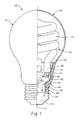
FIGURE 1 is an elevational view, partly in cross-section, of a lamp assembly that includes an outer envelope and a ballast circuit within the outer envelope illustrating a protective shield surrounding the ballast circuit according to an exemplary embodiment of the present disclosure. -
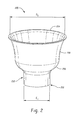
FIGURE 2 is a perspective view of a protective shield according to an exemplary embodiment of the present disclosure. - Shown in
Figure 1 is alamp assembly 100 that includes aninner assembly 102 having alight source 104 and electronics member or printed circuit board, often referred to as aballast circuit 106. Theballast circuit 106 is oftentimes incorporated into a lamp housing orsupport member 108 that supports the ballast circuit, the light source, and provides mechanical and electrical connection of the various lamp components. Enclosing the inner assembly is an outer envelope orbulb 120 which is preferably a light transmissive material, such as glass, that encloses an inner cavity dimensioned to receive the inner assembly therein. More particularly, the outer envelope adopts the general conformation of an A-line lamp having an enlarged generally sphericalfirst portion 122 surrounding thelight source 104 at one end and transitioning into a reduceddimensioned neck 124 at the other end interconnected with thespherical portion 122 through a tapered region. The outer envelope typically has a generally constant wall thickness that terminates in an opening at afirst end 128 disposed adjacent a conventional electrically conductive base 138, shown here as a threaded Edison base orshell 140. The threadedshell 140 is separated from anend contact 142 by aninsulating material 144. The base 138, and particularly thecontact 142 and threadedregion 140 thereof, are received in an associated lamp socket (not shown) to establish electrical and mechanical connection of the lamp assembly. Of course, other lamp bases such as conventional plug-in type connections that establish mechanical and electrical connection between the lamp assembly and an associated electrical socket can be used without departing from the scope and intent of the present disclosure. - The
light source 104 is a compact fluorescent lamp (CFL) (shown here as a spiral CFL) that includes first and second ends orlegs 152, 154 (not shown) that extend generally parallel to one another and in a longitudinal direction that is generally parallel to a central lamp axis of thelamp assembly 100. These legs receive electrodes at opposite ends of an elongated discharge path that includes each leg and an intermediate discharge path which in this embodiment is the helical or spiral lamp arrangement. - The
light source 104 and theballast circuit 106 are held within theouter envelope 120 and relative to each other by thesupport 108 and further by an elasticprotective shield 200. The elasticprotective shield 200 prevents electric shocks and adds protection against mechanical vibrations. The elasticprotective shield 200 is dimensioned to surround at least a portion of thelight source 104 and preferably surrounds an interconnection of theballast circuit 106 with the light source. As further illustrated inFIGURE 2 , the elasticprotective shield 200 has a contour that substantially conforms to a contour of theouter envelope 120. Particularly, the shield has an open first orlower end 252 having a diameter D1 that accommodates a lower portion of the printed circuit board/support 108. An outer surface of the first and is dimensioned for receipt in the Edison base, although as exemplified inFigure 2 , the shield need not extend along he full length of the base 138. Rather, the shieldfirst end 252 substantially covers the printedcircuit board 108. Theopening 252 is dimensioned at D1 to receive electrical leads (unnumbered) that extend from mechanical and electrical connection with theshell 140 andcontact 142, and also mechanically and electrically connect with the printed circuit board/ballast circuit. The elasticprotective shield 200 extends in surrounding relation over at least terminal ends portions of the first andsecond legs 152, 154 (not shown). The base 138 is configured to receive a terminal end of theouter envelope 120 and the elasticprotective shield 200 has afirst portion 250 surrounding theballast circuit 106 and is received within the base 138. In an exemplary embodiment, the elasticprotective shield 200 has a contour that substantially conforms to a contour of theenvelope 120. - The elastic
protective shield 200 has atransition portion 256 that expands radially outwardly in substantially the same contour as the envelope in this region of the lamp. Thetransition portion 256 of the shield interconnects the narrower first end with asidewall 258. Thesidewall 258 in turn extends along theneck 124 and thus the shield continues to be interposed between the glass of the outer envelope (which can potentially break) and the ballast. Thesidewall 258 also steadily increases in dimension as they sidewall terminates at an openupper end 254 that extends to or beyond a height of the ballast. Preferably, theupper end 254 has a radial lip that extends outwardly into abutting engagement with an inner surface of theouter envelope 120 along the interface between the generallyspherical portion 122 and theneck 124. Thesecond end 254 has an open diameter D2 that is substantially greater than the opening D1 at the first end and is dimensioned to accommodate theballast 106 and associatedsupport 108 therein, as well as thelegs 152 of the CFL. - The elastic
protective shield 200 is formed from an electrically insulating material. In an exemplary embodiment, the elasticprotective shield 200 is a silicone or other electrically insulating material. Silicone is desired because of the elastic nature of the material and the thermal stability of the material over a wide range of temperatures that may be encountered with a lamp. Incorporation of the generally annular, elastic, electrically insulating,protective shield 200 that is radially interposed between (i) the CFL legs and the outer envelope (ii) the ballast and the outer envelope, and (iii) the electrical/mechanical connection of the leads, ballast, and CFL legs, and the outer envelope. In this manner, consumers obtain additional protection from possible electrical shock if the outer envelope is inadvertently broken. Likewise, the glass wall (outer envelope) thickness may be minimized since the protection shield adds further mechanical protection. - The disclosure has been described with reference to the preferred embodiments. Clearly, modifications, variations and alterations will occur to others upon reading and understanding the preceding detailed description. It is intended that the disclosure be construed as including all such modifications, variations and alterations.
- 1. A compact fluorescent lamp assembly comprising:
- a compact fluorescent light source;
- a ballast operatively connected to and controlling operation of the light source;
- an outer light transmissive envelope surrounding the light source; and
- an elastic protective shield surrounding the ballast.
- 2. The lamp assembly of clause 1 wherein the elastic protective shield is dimensioned to surround at least a portion of the light source.
- 3. The lamp assembly of any preceding clause wherein the elastic protective shield surrounds an interconnection of the ballast with the light source.
- 4. The lamp assembly of any preceding clause wherein the light source includes first and second legs having cathodes therein and the elastic protective shield extends in surrounding relation over at least terminal end portions of the first and second legs.
- 5. The lamp assembly of any preceding clause further comprising a base that receives a terminal end of the envelope therein and wherein the elastic protective shield has a first portion surrounding the ballast and received within the base.
- 6. The lamp assembly of any preceding clause wherein the elastic protective shield has a contour that substantially conforms to a contour of the envelope.
- 7. The lamp assembly of any preceding clause wherein the elastic protective shield is formed from an electrically insulating material.
- 8. The lamp assembly of any preceding clause wherein the elastic protective shield is formed from a silicone.
- 9. The lamp assembly of any preceding clause wherein the elastic protective shield has a contour that substantially conforms to a contour of the envelope.
- 10. The lamp assembly of any preceding clause wherein the elastic protective shield has an open first end having a diameter D1 and an open second end having a diameter D2 that is greater than D1.
- 11. The lamp assembly of any preceding clause wherein the elastic protective shield has a general cup-shape in which a base wall portion has a small opening that receives electrical leads therethrough for connection with the ballast, a sidewall that encloses a perimeter of the ballast, and an open end that extends beyond a height of the ballast.
- 12. A method of forming a compact fluorescent lamp assembly comprising:
- providing a compact fluorescent light source and a ballast for operating the light source;
- providing an outer envelope for enclosing the light source and at least a portion of the ballast; and
- providing an elastic shield that surrounds the ballast.
- 13. The method of any preceding clause wherein the elastic shield providing step includes interposing the elastic shield between the ballast and that portion of the outer envelope enclosing the ballast.
- 14. The method of any preceding clause wherein the elastic shield providing step includes forming the elastic shield from an electrically insulative material.
- 15. The method of any preceding clause wherein the elastic shield providing step includes forming the elastic shield from a silicone.
- 16. The method of any preceding clause wherein the elastic shield providing step includes contouring the elastic shield to conform to a contour of the outer envelope.
- 17. The method of any preceding clause wherein the outer envelope providing step includes forming the outer envelope to have a generally spherical first portion that surrounds the light source and transitions into a reduced dimensioned neck that at least partially encloses the ballast.
- 18. The method of any preceding clause wherein the elastic shield providing step includes dimensioning the elastic shield for receipt in the neck.
- 19. The method of any preceding clause wherein the elastic shield providing step includes forming the shield into a generally cup-shaped member having a base with an opening for closely receiving lead wires therethrough for connection with the ballast, and a continuous sidewall extending outwardly from the base in surrounding relation with the ballast.
- 20. The method of any preceding clause wherein the elastic shield includes an open end axially spaced from the base that tapers outwardly.
Claims (10)
- A compact fluorescent lamp assembly (100) comprising:a compact fluorescent light source (104);a ballast (106) operatively connected to and controlling operation of the light source (104);an outer light transmissive envelope (120) surrounding the light source (104); andan elastic protective shield (200) surrounding the ballast (106).
- The lamp assembly (100) of claim 1 wherein the elastic protective shield (200) is dimensioned to surround at least a portion of the light source (104).
- The lamp assembly (100) of any preceding claim wherein the elastic protective shield (200) surrounds an interconnection of the ballast (106) with the light source (104).
- The lamp assembly (100) of any preceding claim further comprising a base that receives a terminal end of the envelope (120) therein and wherein the elastic protective shield (200) has a first portion surrounding the ballast (106) and received within the base.
- The lamp assembly (100) of any preceding claim wherein the elastic protective shield (200) has a contour that substantially conforms to a contour of the envelope (120).
- The lamp assembly (100) of any preceding claim wherein the elastic protective shield (200) is formed from an electrically insulating material.
- The lamp assembly (100) of any preceding claim wherein the elastic protective shield (200) has a contour that substantially conforms to a contour of the envelope (120).
- The lamp assembly (100) of any preceding claim wherein the elastic protective shield (200) has an open first end having a diameter D1 and an open second end having a diameter D2 that is greater than D1.
- The lamp assembly (100) of any preceding claim wherein the elastic protective shield (200) has a general cup-shape in which a base wall portion has a small opening that receives electrical leads therethrough for connection with the ballast (106), a sidewall that encloses a perimeter of the ballast (106), and an open end that extends beyond a height of the ballast (106).
- A method of forming a compact fluorescent lamp assembly (100) comprising:providing a compact fluorescent light source (104) and a ballast (106) for operating the light source (104);providing an outer envelope (120) for enclosing the light source (104) and at least a portion of the ballast (106); andproviding an elastic shield (200) that surrounds the ballast (106).
Applications Claiming Priority (1)
| Application Number | Priority Date | Filing Date | Title |
|---|---|---|---|
| US12/787,817 US8264130B2 (en) | 2010-05-26 | 2010-05-26 | Safety protection solution for compact fluorescent lamps |
Publications (2)
| Publication Number | Publication Date |
|---|---|
| EP2390901A2 true EP2390901A2 (en) | 2011-11-30 |
| EP2390901A3 EP2390901A3 (en) | 2014-04-23 |
Family
ID=44359697
Family Applications (1)
| Application Number | Title | Priority Date | Filing Date |
|---|---|---|---|
| EP11166984.2A Withdrawn EP2390901A3 (en) | 2010-05-26 | 2011-05-20 | Compact fluorescent lamp with a safety shield |
Country Status (3)
| Country | Link |
|---|---|
| US (1) | US8264130B2 (en) |
| EP (1) | EP2390901A3 (en) |
| CN (1) | CN102315082A (en) |
Families Citing this family (1)
| Publication number | Priority date | Publication date | Assignee | Title |
|---|---|---|---|---|
| US20130201696A1 (en) * | 2010-09-27 | 2013-08-08 | Toshiba Lighting & Technology Corporation | Bulb-shaped lamp and lighting device |
Family Cites Families (12)
| Publication number | Priority date | Publication date | Assignee | Title |
|---|---|---|---|---|
| JPS5763764A (en) * | 1980-10-02 | 1982-04-17 | Matsushita Electric Ind Co Ltd | Single base type fluorescent lamp device |
| US4527089A (en) | 1983-04-01 | 1985-07-02 | Gte Products Corporation | Compact fluorescent lamp |
| US4739222A (en) * | 1985-05-07 | 1988-04-19 | Hitachi, Ltd. | Compact fluorescent lamp with a screw base |
| GB8604117D0 (en) * | 1986-02-19 | 1986-03-26 | Mclauchlan R A | Light tube protector |
| US5691598A (en) | 1995-12-07 | 1997-11-25 | General Electric Company | Fluorescent lamp with thermal heat shield between lamp tube and ballast circuitry |
| US6064155A (en) | 1998-05-04 | 2000-05-16 | Matsushita Electric Works Research And Development Labratory Inc | Compact fluorescent lamp as a retrofit for an incandescent lamp |
| US6204602B1 (en) * | 1999-05-17 | 2001-03-20 | Magnetek, Inc. | Compact fluorescent lamp and ballast assembly with an air gap for thermal isolation |
| US6614039B2 (en) * | 1999-06-23 | 2003-09-02 | Brad C. Hollander | Hermetically sealed ultraviolet light source |
| US6794801B2 (en) * | 2001-10-31 | 2004-09-21 | Toshiba Lighting & Technology Corporation | Compact selfballasted fluorescent lamp and luminaire |
| USD581580S1 (en) | 2007-03-28 | 2008-11-25 | International Growers Supply Incorporated | Ballast cover |
| HU0700331D0 (en) * | 2007-05-10 | 2007-07-30 | Ge Hungary Zrt | Compact fluorescent lamp with outer envelope and method for manufacturing |
| JP2009199885A (en) * | 2008-02-21 | 2009-09-03 | Seiki Uchiyama | Electric bulb and method of protecting the same |
-
2010
- 2010-05-26 US US12/787,817 patent/US8264130B2/en not_active Expired - Fee Related
-
2011
- 2011-05-20 EP EP11166984.2A patent/EP2390901A3/en not_active Withdrawn
- 2011-05-26 CN CN2011101537439A patent/CN102315082A/en active Pending
Non-Patent Citations (1)
| Title |
|---|
| None |
Also Published As
| Publication number | Publication date |
|---|---|
| EP2390901A3 (en) | 2014-04-23 |
| US20110291563A1 (en) | 2011-12-01 |
| US8264130B2 (en) | 2012-09-11 |
| CN102315082A (en) | 2012-01-11 |
Similar Documents
| Publication | Publication Date | Title |
|---|---|---|
| EP2156463B1 (en) | Compact fluorescent lamp with outer envelope and method for manufacturing such lamp | |
| EP2171743B1 (en) | Ignition aid and fitting shroud for discharge lamp | |
| EP2227820B1 (en) | Compact fluorescent lamp with mechanical support means and starting aid | |
| EP1175131A2 (en) | Compact fluorescent lamp | |
| US8264130B2 (en) | Safety protection solution for compact fluorescent lamps | |
| EP0389937A2 (en) | Means for converting a lamp with a screw-type base into a lamp with a bi-pin base | |
| US7101229B2 (en) | Adapter for mogul base open fixture lamps | |
| US8330370B2 (en) | Compact fluorescent lamp with improved thermal management | |
| JP2004265640A (en) | Discharge lamp, discharge lamp socket, discharge lamp device, and discharge lamp lighting device | |
| CA2147517C (en) | Lampholder with mogul base | |
| US7025612B1 (en) | Base for a mogul-based lamp | |
| US8604682B2 (en) | Built-in lamp with cable, in particular for aerodrome lighting | |
| CA2442941C (en) | End-of-life protection for compact fluorescent lamps | |
| US20080224614A1 (en) | Looped Frame Arc Tube Mounting Assembly for Metal Halide Lamp | |
| JP2002298608A (en) | Bulb-shaped fluorescent lamp | |
| US5550722A (en) | Electric lamp | |
| JP2005108699A (en) | Bulb type fluorescent lamp and lighting fixture | |
| EP0583034A1 (en) | Electric lamp | |
| US5834884A (en) | Systematic configuration of compact fluorescent lamps for operation in a single-type ballast | |
| JP2999459B1 (en) | Incandescent lamp and socket with base and incandescent lamp device | |
| EP2439765B1 (en) | Shrouded discharge lamp with reduced arcing | |
| JP2007323940A (en) | Discharge lamp | |
| JP2009129569A (en) | Discharge lamp and its manufacturing method | |
| JP2015504585A (en) | High pressure gas discharge lamp |
Legal Events
| Date | Code | Title | Description |
|---|---|---|---|
| AK | Designated contracting states |
Kind code of ref document: A2 Designated state(s): AL AT BE BG CH CY CZ DE DK EE ES FI FR GB GR HR HU IE IS IT LI LT LU LV MC MK MT NL NO PL PT RO RS SE SI SK SM TR |
|
| AX | Request for extension of the european patent |
Extension state: BA ME |
|
| PUAI | Public reference made under article 153(3) epc to a published international application that has entered the european phase |
Free format text: ORIGINAL CODE: 0009012 |
|
| PUAL | Search report despatched |
Free format text: ORIGINAL CODE: 0009013 |
|
| AK | Designated contracting states |
Kind code of ref document: A3 Designated state(s): AL AT BE BG CH CY CZ DE DK EE ES FI FR GB GR HR HU IE IS IT LI LT LU LV MC MK MT NL NO PL PT RO RS SE SI SK SM TR |
|
| AX | Request for extension of the european patent |
Extension state: BA ME |
|
| RIC1 | Information provided on ipc code assigned before grant |
Ipc: H01J 61/32 20060101AFI20140318BHEP Ipc: H01J 5/50 20060101ALI20140318BHEP Ipc: F21V 15/00 20060101ALI20140318BHEP |
|
| STAA | Information on the status of an ep patent application or granted ep patent |
Free format text: STATUS: THE APPLICATION IS DEEMED TO BE WITHDRAWN |
|
| 18D | Application deemed to be withdrawn |
Effective date: 20141024 |