EP2390636B1 - Bedingungsbasiertes Überwachungssystem basierend auf einem Radarsensor - Google Patents
Bedingungsbasiertes Überwachungssystem basierend auf einem Radarsensor Download PDFInfo
- Publication number
- EP2390636B1 EP2390636B1 EP11166288.8A EP11166288A EP2390636B1 EP 2390636 B1 EP2390636 B1 EP 2390636B1 EP 11166288 A EP11166288 A EP 11166288A EP 2390636 B1 EP2390636 B1 EP 2390636B1
- Authority
- EP
- European Patent Office
- Prior art keywords
- radar
- vibration
- machine
- sensor
- sensors
- Prior art date
- Legal status (The legal status is an assumption and is not a legal conclusion. Google has not performed a legal analysis and makes no representation as to the accuracy of the status listed.)
- Active
Links
- 238000012544 monitoring process Methods 0.000 title description 17
- 238000006073 displacement reaction Methods 0.000 claims description 25
- 238000012545 processing Methods 0.000 claims description 18
- 238000000034 method Methods 0.000 claims description 17
- 238000012423 maintenance Methods 0.000 claims description 14
- 238000005259 measurement Methods 0.000 claims description 14
- 230000033001 locomotion Effects 0.000 claims description 11
- 230000036541 health Effects 0.000 claims description 9
- 230000009471 action Effects 0.000 claims description 7
- 230000003595 spectral effect Effects 0.000 claims description 7
- 230000002123 temporal effect Effects 0.000 claims description 5
- 238000007405 data analysis Methods 0.000 description 5
- 238000004458 analytical method Methods 0.000 description 4
- 238000004891 communication Methods 0.000 description 4
- 230000003287 optical effect Effects 0.000 description 4
- 230000008569 process Effects 0.000 description 4
- 238000013459 approach Methods 0.000 description 3
- 230000008859 change Effects 0.000 description 3
- 230000006870 function Effects 0.000 description 3
- 230000035945 sensitivity Effects 0.000 description 3
- 230000005540 biological transmission Effects 0.000 description 2
- 230000007423 decrease Effects 0.000 description 2
- 238000010586 diagram Methods 0.000 description 2
- 238000005516 engineering process Methods 0.000 description 2
- 230000000007 visual effect Effects 0.000 description 2
- 230000002159 abnormal effect Effects 0.000 description 1
- 238000005452 bending Methods 0.000 description 1
- 230000002596 correlated effect Effects 0.000 description 1
- 230000000875 corresponding effect Effects 0.000 description 1
- 230000003247 decreasing effect Effects 0.000 description 1
- 238000013461 design Methods 0.000 description 1
- 238000007689 inspection Methods 0.000 description 1
- 238000009434 installation Methods 0.000 description 1
- 230000007257 malfunction Effects 0.000 description 1
- 238000004519 manufacturing process Methods 0.000 description 1
- 239000002184 metal Substances 0.000 description 1
- 238000012986 modification Methods 0.000 description 1
- 230000004048 modification Effects 0.000 description 1
- 238000012806 monitoring device Methods 0.000 description 1
- 230000006855 networking Effects 0.000 description 1
- 230000000737 periodic effect Effects 0.000 description 1
- 230000000246 remedial effect Effects 0.000 description 1
- 238000001228 spectrum Methods 0.000 description 1
- 230000000153 supplemental effect Effects 0.000 description 1
Images

Classifications
-
- G—PHYSICS
- G01—MEASURING; TESTING
- G01H—MEASUREMENT OF MECHANICAL VIBRATIONS OR ULTRASONIC, SONIC OR INFRASONIC WAVES
- G01H9/00—Measuring mechanical vibrations or ultrasonic, sonic or infrasonic waves by using radiation-sensitive means, e.g. optical means
Definitions
- CBM Condition Based Maintenance
- Vibration sensing using accelerometers is the standard measurement for machine monitoring. These sensors measure vibration at the location where they are attached to the machine.
- accelerometers come in various forms, their basic principles remains the same-make physical contact with the machine being monitored and generate a signal that is proportional to the harmonic motion experienced at the point of contact. Permanently installed accelerometers are often attached to the machine with screws and wired connections. Besides their intrusive nature (designed while the machine is assembled), such sensors cannot be mounted on many moving parts, making it impossible to monitor "locations" that may be critical from a vibration standpoint.
- Permanently mounted accelerometers are often complemented with handheld vibration monitoring equipment. However, signals generated from sensors mounted "far away” from a machine pick up background noises such as those generated by a helicopter body. This can obscure important signatures of failing gears or bearings. Further, it may not be safe to approach the machine with an attachable handheld sensor and try to make the sensor head reach the remote location of interest.
- the present invention provides a sensing system and a method as defined in the independent claims 1 and 7, respectively.
- the sensing system comprises a radar-based vibration sensor and processing unit.
- the radar-based vibration sensor is configured to obtain vibration data from mechanical operation of a component or series of components in a machine of interest.
- the processing unit is configured to analyze the data obtained by the at least one radar-based vibration sensor, and provide indications related to a status of the mechanical operation of the one or more components in the machine of interest.
- data from multiple vibration sensors may be fused and factored in the processing system, such as data collected from a plurality of radar-based vibration sensors, and a plurality of machine-mounted vibration sensors (i.e., accelerometers).
- a steering system is configured to direct and steer the radar-based vibration sensor to collect the vibration data from different locations of mechanical operation for the machine of interest. From the indications calculated from the processing unit, various machine health indicators and potential maintenance actions may be suggested.
- the functions or algorithms described herein may be implemented in software or a combination of software and human or enterprise implemented procedures in one embodiment.
- the software may consist of computer executable instructions stored on computer readable media such as memory or other type of storage devices. Further, such functions correspond to modules, which are software, hardware, firmware, or any combination thereof. Multiple functions may be performed in one or more modules as desired, and the embodiments described are merely examples.
- the software may be executed on a digital signal processor, ASIC, microprocessor, or other type of processor operating on a computer system, such as a personal computer, server or other computer system.
- one or more radar-based displacement sensors may be used to gather vibration information from an operating machine.
- the radar-based displacement sensor is steered or directed toward multiple regions of interest on the operating machine to gather vibration information from the multiple regions of interest.
- the data produced from the one or more radar based displacement sensors may be processed in a condition monitoring system or other sensing system that allows monitoring of the entire machine and a plurality of sensing locations.
- a condition monitoring system or other sensing system that allows monitoring of the entire machine and a plurality of sensing locations.
- maintenance information and other monitoring data may be extracted from the sensing system and provided to a user for remedial action.
- accelerometers Despite an accelerometer's ability to monitor instrumented parts of the machine, relying on the use of accelerometers in a condition monitoring system or like sensing system may result in a number of location and design limitations (particularly for permanent sensor installation). Further, economic reasons may limit the locations where accelerometers can be installed and deployed.
- Tethered accelerometer heads suffer the same limitations as its permanently installed counterpart. That is, tethered sensors need to make mechanical contact with the machine and often require supplemental measurements such as an optical tachometer. Handheld accelerometers can provide a wider range, but their accuracy depends on the skill level of the technician. Further, it may not be safe to approach the machine with an attachable handheld sensor and try to make the sensor head reach the remote location of interest.
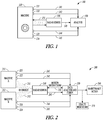
- a sensing system such as the example system illustrated in FIG. 1 may be used to monitor an entire machine with moving parts, using a scanning radar-based displacement sensor, permanently mounted sensors, and back-end software to enable maintenance related decision making.
- Structural problems can develop anywhere in the machine and are not restricted to the location where embedded sensors may be located. Collecting data with the use of scanning radar-based vibration sensors provides the ability to monitor large areas of the "entire" machine, while also analyzing well-known weak spots in the machine as necessary for rapid, accurate assessment of machine health.
- the presently disclosed sensing system may be deployed to monitor a wide variety of rotating machinery and mechanical components within a machine.
- This rotating machinery may include one or more of an electric motor, pulleys, gearboxes, shafts, bearings, drivelines, and like mechanical parts.
- abnormal harmonic readings may indicate rotational misbalance as a result from a failing or misbalanced component.
- the sensing system may process these harmonic readings and other temporal and spectral data to detect the status of various operational components.
- the sensing system may specifically generate health indicators to alert users to warnings and failures such as stator breaks, rotor bending, wiring, shaft misalignment, gear tooth breaks, and bearing spalls.
- Use of the displacement vibration sensor within the sensing system provides a non-intrusive, non-contact approach to detect failures without adding conventional accelerometers. This not only makes it easy to retrofit legacy machines, but also allows the same apparatus to monitor more than one machine at the same time.
- An example sensing system includes several components used to provide sensing measurements and direct operation of sensors as necessary.
- the system includes a stand-off sensor that observes the machine for vibration induced displacements, one or more of permanently mounted sensors that provide measurement of machine condition at point locations, a steering system that steers the stand-off sensor to observe specific regions of interest within the machine, a software module that analyzes the data from various sensors, and a decision support module that calculates the machine health indicators and potential maintenance actions.
- the stand-off sensor is a radar based displacement sensor.
- the stand-off sensor may use Doppler-based radar techniques to transmit and measure signals aimed at a specific object of interest.
- the stand-off sensor may be electronically or mechanically steered towards the specific object for monitoring.
- the steering may be either periodic or trigger-based, and driven by an automated control.
- the steering subsystem may be used to position an electromechanically operated phased-array radar antenna within the stand-off sensor.
- a non-contact, radar-based sensor may be configured to sense vibration from a considerable distance (e.g., 4 feet), and provide a wide field of view that could be adjusted to monitor the entire machine or specific parts of the machine. Further, the sensor may be tuned to detect only the motion of the machinery and reject background vibration, providing vibration data from under-instrumented parts of the machine without incurring additional costs. This makes acquiring vibration data from previously un-instrumented parts not only cost-effective, but also safe.
- the radar antenna of the sensor may also be configured to have a tunable or narrow field of view, such as providing no more than a 10-degree field of view and therefore could be deployed as a handheld or spot sensor.
- a radar-based displacement sensor used in the presently disclosed sensing system transmits RF energy toward a target area to be monitored.
- the RF energy reflects from metal surfaces and edges within the target area and returns to the sensor.
- the sensor may be calibrated to reject any movement that is common to the target and the antenna.
- the sensing system may process and analyze data from a plurality of displacement sensors or in combination with a plurality of fixed accelerometers to identify and reject invalid data.
- the data produced by the radar-based displacement sensor may be therefore refined or processed at the sensor or within a processing module separate to the sensor.
- Machine 110 may contain a plurality of moving parts or components that are intended to be monitored to ensure proper mechanical operation.
- a series of accelerometers 121, 122, 123, 124 may be attached to or otherwise directly proximate to various moving components of the machine 110.
- a radar sensor 130 may be positioned auxiliary to accelerometers 121, 122, 123, 124, or may be positioned as a portable stand alone sensor. For example, an operator may bring the radar sensor 130 to a factory floor and position it on a tripod at a distance (such as less than four feet) from the machine 110 when suspecting performance issues, or when the machine operation is in need of a period checkup.
- the sensor 130 may be configured to collect vibration or displacement data for a period of time, such as over a few days, allowing the data collected over this period of time to be analyzed for indicators of possible problems such as motor damage or wear.
- the radar sensor 130 transmits and receives radar energy 131 to and from the machine 110, collecting vibration data from the whole or a large part of the machine.
- the vibration data including temporal or spectral data collected from the combination of accelerometers 121, 122, 123, 124 and the radar sensor 130 is then transmitted to an analysis component 150 as represented by lines 141, 142, 144, 145, and 143 respectively.
- the lines may represent hardwired communication lines, or wireless connections.
- a certain measured threshold of change e.g., an amplitude of velocity or frequency shift/new frequency
- a certain measured threshold of change may be configured to create or otherwise initiate a request for maintenance within the analysis component 150.
- information from the radar sensor 130 may be collected as a time sampled data or Fast Fourier Transform (FFT) of the data or frequencies and amplitudes of the spectrum peaks.
- FFT Fast Fourier Transform
- Information from different peaks can be combined, for example, to enable the velocity at the moving parts of the machine to be correlated with the load.
- the loading condition may be used for the interpretation of the spectral peaks corresponding to vibrations which may shift or broaden for different loads, such as may be measured from bearing vibrations.
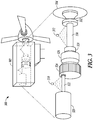
- FIG. 2 illustrates an embodiment of the invention providing a configuration of a sensor system 200 configured to monitor operation of multiple machines or components with use of a radar-based sensor.
- machine A 211 and machine B 212 are monitored with a series of permanently mounted sensors, such as accelerometers 221, 222, and 223, 224 respectively.
- the radar-based sensor 230 may configured to direct RF energy towards one or both of machine A 211 and machine B 212 as shown in 231 and 232.
- a steering motion is applied to the radar-based sensor 230 to aim the sensor and direct a single source of RF energy towards one of the machines at a single point in time. This steering motion is communicated to the radar sensor through use of motion instructions 233.
- the radar sensor 230 provides multiple sources of energy to achieve simultaneous monitoring of multiple machines at a single point in time.
- the temporal or spectral data from the sensor 230 is then transmitted as represented at 243 to a data analysis component 240.
- data from the mounted accelerometers 221, 222, 223, 224 is communicated as represented by lines 241, 242, 244, and 245.
- the data analysis component 250 may then fuse in the data from the variety of the permanently mounted sensors 221, 222, 223, 224 and the radar-based sensor 230 to determine the status of larger machine operations as a whole, or the status of specific machine subsystems and processes, based on the comparison of data from a plurality of sensors. This may result in the generation of user indications, such as one or more recommended maintenance actions 260, the generation of health indicators 270, or other useful machine-related information.
- the radar-based sensor may be configured to detect machine vibration and misbalance (such that occurring from bearing damage) at a distance without making any contact with the machine.
- the data produced from these remote measurements may even exceed the performance of a high-quality screw accelerometer mounted directly on the bearing enclosure.
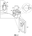
- FIG. 3 provides an illustration of an example monitoring system using a combination of radar-based and permanently mounted sensors to monitor a mechanical system, specifically a horizontal axis wind turbine 300. As depicted, a number of sensors are depicted as being used to monitor the operation of the electrical generating components of the turbine 300 within its nacelle 302.
- two radar-based vibration sensors 310, 312 are placed within the nacelle 302 and adjacent to the mechanical drive used to ultimately rotate generator 320.
- the first radar-based vibration sensor 310 is configured to monitor the high-speed shaft 322 located between generator 320 and gear box 324.
- the second radar-based vibration sensor 312 is configured to monitor the main shaft 330 located between transmission 326 and hub 334, specifically the portion of the main shaft extending between bearings 328 and 332.
- the data from multiple sensors such as radar-based vibration sensors 310, 312 may be compared with each other in the sensing system to compare relative vibration or other harmonics that are constant in operation of the system.
- the data collected from the radar-based vibration sensors 310, 312 may then be transmitted from the sensors to an off-set processing system, using any of a number of wired or wireless networking data connections.
- FIG. 4 provides another illustration of use of the sensor-based system with a portable vibrometer not forming part of the present invention, specifically in conjunction with a handheld inspection device.
- operator 400 aims a radar-based sensor 410 towards a mechanical system; illustrated here as a high-pressure pump 420 such as may be used in a large pump farm.
- the sensor 410 transmits and receives the RF radio signal 430 from one or more moving parts within the high pressure pump 420.
- the operator uses some type of a readout display unit to assist with focusing the radar sensor and to obtain feedback.
- the radio frequency data obtained at the radar sensor 410 may be transmitted to a computing device, here a portable handheld measurement device 440 having a display screen interface 450.
- the handheld measurement device 440 is able to process the RF signals obtained from sensor 410 and provide immediate feedback and measurements related to the sensor readings.
- the data may be transmitted from the radar sensor to another computing system, such as being transmitted from the handheld measurement device 440 using a network connection to an off-site computing system (not illustrated) for analysis and processing.
- the handheld measurement device 440 may be configured to provide a visual indication 450 of the status of the sensor measurements to the operator 400.
- This visual indication may be presented as a graph rendered on a display screen, a textual indicator of measurements, or another illustration or indication rendered on the display screen.
- a variety of other graphical, textual, audio, or tactile indications may be provided to the user through the device 440 to indicate warnings, failures, and other malfunctions of the monitored equipment.
- the radar-based displacement sensor generates RF frequency at 24 GHz, an unregulated frequency band.
- the reflection phase changes proportionally to the displacement of the reflective surface relative to the radar divided by the RF frequency signal wavelength.
- the wavelength of the signal is short (e.g., 1.25 cm) for high sensitivity of the sensor.
- the reflected signal is modulated by the target vibration magnitude, such that any movement that is common to the target and the antenna is rejected.
- the return signals are mixed (beat against each other) with transmitted signals.
- the output signal phase of the sensor follows the radial displacement (in a direction perpendicular to the antenna) of the target in the time domain.
- the output signal is converted in the frequency domain by Fast Fourier Transform (FFT). If the reflecting surfaces in the radar antenna's field of view move at different frequencies or amplitudes, they will contribute different spectral peaks in the sensor signal. Thus, one sensor with a wide field of view is capable of monitoring many moving parts at the same time.
- FFT Fast Fourier Transform
- the sensor may provide high sensitivity that decreases for longer distances, and may also provide an output signal that is decreasing with increased distance.
- a sensor may be configured to detect displacement as small as 0.1 nm at a distance of 50 cm and 0.5 nm at a distance of 133.5 cm.
- the very high sensitivity is due to the very short round-trip time for the return signal (e.g., 3 nsec for 50 cm). Therefore, the local oscillator does not drift much and the phase noise of the sensor is very low. The round-trip time and thus the phase noise are larger for longer distances.
- the amplitude of the sensor decreases proportionally to the distance because the other half of the mixing energy comes from the local oscillator in the sensor and does not change with the distance. Therefore, large sensing distances are feasible for comparatively low transmission power (e.g., 50 mW).
- the radar-based sensor may be used to detect higher harmonic sidebands and higher harmonics than that detected by an accelerometer. Moreover the signal-to-noise ratio (energy in the sidebands divided by the noise energy around the sidebands) may be higher for a radar-based sensor than in an accelerometer.
- a radar-based sensor can be tuned to wide angles or otherwise tuned to a specific field of view to monitor the entire machine or specific parts of the machine, while detecting the motion of the machinery and rejecting background vibration. Therefore, use of a radar-based sensor may have a higher probability of detecting misbalance faults than an accelerometer.
- the cost for the sensing components may be an order of magnitude lower.
- Some embodiments may be capable of wide field sensing with no moving parts. Further embodiments may penetrate nonconductive protection layers, and various embodiments may be made without the need for delicate optical components and connections.
- the radar-based sensor and sensing system may be configured to reject the common mode vibration that may be obstructing the fault signature in machines as well as its insensitivity to surface fouling. For example, this limits optical sensors in weakly supported platforms such as a helicopter body or the gearbox in a wind turbine nacelle.
- warnings and other usable information can be generated and transmitted in a rapid fashion with significant advantages over existing sensing techniques.
- FIG. 5 A block diagram of an example computer system that performs data analysis from the various sensors, and includes a decision support module that calculates the machine health indicators and potential maintenance actions and executes other necessary analysis and programming is shown in FIG. 5 .
- a general computing device in the form of a computer 510 may include a processing unit 502, memory 504, removable storage 512, and non-removable storage 514.
- Memory 504 may include volatile memory 506 and non-volatile memory 508.
- Computer 510 may include - or have access to a computing environment that includes - a variety of computer-readable media, such as volatile memory 506 and non-volatile memory 508, removable storage 512 and non-removable storage 514.
- Computer storage includes random access memory (RAM), read only memory (ROM), erasable programmable read-only memory (EPROM) & electrically erasable programmable read-only memory (EEPROM), flash memory or other memory technologies, compact disc read-only memory (CD ROM), Digital Versatile Disks (DVD) or other optical disk storage, magnetic cassettes, magnetic tape, magnetic disk storage or other magnetic storage devices, or any other medium capable of storing computer-readable instructions.
- Computer 510 may include or have access to a computing environment that includes input 516, output 518, and a communication connection 520.
- the computer may operate in a networked environment using a communication connection to connect to one or more remote computers.
- the remote computer may include a personal computer (PC), server, router, network PC, mobile device, a peer device or other common network node, or the like.
- the communication connection may include a Local Area Network (LAN), a Wide Area Network (WAN) or other networks.
- LAN Local Area Network
- WAN Wide Area Network
- Computer-readable instructions to execute methods and algorithms described above may be stored on a computer-readable medium such as illustrated at a program storage device 525 are executable by the processing unit 502 of the computer 510.
- a hard drive, CD-ROM, and RAM are some examples of articles including a computer-readable medium.
- a user interface is provided in connection with the computer system, such as a touch screen device for providing both input 516 and output 518.
- the presently described sensing system and radar-based sensors may be implemented in a variety of settings, including but not limited to industrial and aerospace applications. Those skilled in the art would recognize that variations to the presently described embodiments may be used to apply the presently disclosed techniques to a variety of other mechanical and electromechanical applications and fields of use.
Landscapes
- Physics & Mathematics (AREA)
- General Physics & Mathematics (AREA)
- Testing Of Devices, Machine Parts, Or Other Structures Thereof (AREA)
- Measurement Of Mechanical Vibrations Or Ultrasonic Waves (AREA)
Claims (10)
- Sensorsystem (100; 200), umfassend:einen radargestützten Vibrationssensor (130; 230), wobei der radargestützte Vibrationssensor (130; 230) konfiguriert ist zum Bereitstellen von Vibrationsdaten (143; 243) von einem mechanischen Betrieb einer interessierenden Maschine (110; 211, 212);ein Lenksystem, das konfiguriert ist zum Ausrichten des radargestützten Vibrationssensors (230) mithilfe von Bewegungsbefehlen (233), um den radargestützten Vibrationssensor (230) so auszurichten, dass er die Radarenergie (231, 232) auf bestimmte Orte des mechanischen Betriebs der interessierenden Maschine (110; 211, 212) entweder regelmäßig oder aufgrund von erfassten Vibrationen fokussiert, die innerhalb einer Verarbeitungseinheit (250) ermittelt werden, und zum Sammeln der Vibrationsdaten von den bestimmten Orten; undeine Verarbeitungseinheit (150; 250), die konfiguriert ist zum Analysieren der Vibrationsdaten (143; 243), die von dem radargestützten Vibrationssensor (130; 230) bereitgestellt werden, und zum Bereitstellen von Anweisungen, die sich auf einen Zustand des mechanischen Betriebs der Orte des mechanischen Betriebs der interessierenden Maschine (110; 211, 212) beziehen.
- System nach Anspruch 1, wobei der radargestützte Vibrationssensor (130; 230) ein Wegsensor zum Übertragen von Radarsignalen (131; 231, 232) ist, der Doppler-Radartechniken verwendet, und wobei die Vibrationsdaten (143; 243) Zeit- und Spektraldaten aufweisen, die sich auf den mechanischen Betrieb der interessierenden Maschine (110; 211, 212) beziehen.
- System nach Anspruch 1, wobei der radargestützte Vibrationssensor (130; 230) ein abstimmbares Blickfeld bereitstellt, um sich auf einen bestimmten Bereich (211, 212) des mechanischen Betriebs für die interessierenden Maschine zu fokussieren.
- System nach Anspruch 1, wobei die Verarbeitungseinheit (150; 250) außerdem mit einem Entscheidungsunterstützungsmodul funktionsfähig verbunden ist, das konfiguriert ist zum Berechnen mindestens eines von Maschinenzustandsindikatoren (270) und potenziellen Wartungsarbeiten (260) in Verbindung mit den Anweisungen, die sich auf den Zustand des mechanischen Betriebs der interessierenden Maschine (110; 211, 212) beziehen.
- System nach Anspruch 1, das außerdem umfasst:eine Vielzahl von Vibrationssensoren (221, 222, 223, 224), die an die interessierenden Maschine (110; 211, 212) montiert sind, wobei die an der Maschine montierten Vibrationssensoren (221, 222, 223, 224) konfiguriert sind zum Erhalten von Vibrationsdaten von dem mechanischen Betrieb von Komponenten in der Nähe von Montageorten; undwobei die Verarbeitungseinheit (250) außerdem konfiguriert ist zum Analysieren von Daten, die von den an der Maschine montierten Vibrationssensoren (221, 222, 223, 224) bereitgestellt werden, und zum Vereinigen der Daten der an der Maschine montierten Vibrationssensoren (221, 222, 223, 224) mit den Informationen von dem radargestützten Vibrationssensor (230).
- System nach Anspruch 5, das außerdem umfasst:einen oder mehrere radargestützte Vibrationssensoren (312) zusätzlich zu dem radargestützten Vibrationssensor (230; 310), die konfiguriert sind zum Erhalten von Vibrationsdaten von dem mechanischen Betrieb von mehreren Komponentenorten (322, 330) in der interessierenden Maschine (300);wobei die Verarbeitungseinheit (250) außerdem konfiguriert ist zum Analysieren der Daten, die von dem einen oder den mehreren zusätzlichen radargestützten Vibrationssensoren (312) bereitgestellt werden, und zum Vereinigen der Daten, die von dem einen oder den mehreren zusätzlichen radargestützten Vibrationssensoren (312) bereitgestellt werden, mit den Informationen von den an der Maschine montierten Vibrationssensoren (221, 222, 223, 224) und von dem radargestützten Vibrationssensor (230; 310); undwobei mindestens einer der an der Maschine montierten Vibrationssensoren (221, 222, 223, 224) ein Beschleunigungsmesser ist.
- Verfahren, das durch ein Sensorsystem (100; 200) ausgeführt wird, umfassend:Sammeln von Vibrationsdaten (143; 243) von einem radargestützten Wegsensor (130; 230), wobei der radargestützte Wegsensor (130; 230) von einem Lenksystem ausgerichtet wird, das konfiguriert ist zum Ausrichten des radargestützten Vibrationssensors (230) mithilfe von Bewegungsbefehlen (233), um die Radarenergie (231, 232) auf bestimmte Orte des mechanischen Betriebs der interessierenden Maschine (110; 211, 212) entweder regelmäßig oder aufgrund von erfassten Vibrationen zu fokussieren, die innerhalb einer Verarbeitungseinheit (250) ermittelt werden, und zum Sammeln der Vibrationsdaten von den bestimmten Orten, um Vibrationen von der interessierenden Maschine (110; 211, 212) zu messen, und wobei die Vibrationsdaten Zeit- und/oder Spektraldaten aufweisen;Verarbeiten der Vibrationsdaten (143; 243), um die Vibrationsmessungen von dem radargestützten Wegsensor (130; 230) zu analysieren, und Ableiten eines Zustands des mechanischen Betriebs für die interessierende Maschine (110; 211, 212); undBereitstellen von Benutzeranweisungen (260, 270), die sich auf den Zustand des mechanischen Betriebs der interessierenden Maschine (110; 211, 212) beziehen.
- Verfahren nach Anspruch 7, das außerdem umfasst:Bewerten des Zustands des mechanischen Betriebs für die der im Betrieb befindliche Maschine (110; 211, 212), um die vorgeschlagenen Wartungsarbeiten (260) und/oder Maschinenzustandsindikatoren (270) zu erzeugen; undBereitstellen der vorgeschlagenen Wartungsarbeiten (260) und/oder Maschinenzustandsindikatoren (270) in Verbindung mit den Benutzeranweisungen.
- Verfahren nach Anspruch 7, das außerdem umfasst:Sammeln von Vibrationsdaten von montierten Vibrationssensoren (121, 122, 123, 124; 221, 222, 223, 224), die konfiguriert sind zum Messen von Vibrationen aus einem interessierenden Bereich in der Nähe der montierten Vibrationssensoren (121, 122, 123, 124; 221, 222, 223, 224) an der im Betrieb befindlichen Maschine (110; 211; 212); undVerarbeiten der Vibrationsdaten, die von den montierten Vibrationssensoren (121, 122, 123, 124; 221, 222, 223, 224) gesammelt werden, und Kombinieren der Vibrationsdaten, die von den montierten Vibrationssensoren (121, 122, 123, 124; 221, 222, 223, 224) gesammelt werden, mit den Vibrationsdaten, die von dem radargestützten Wegsensor (130; 230) gesammelt werden.
- Verfahren nach Anspruch 9, das außerdem umfasst:Sammeln von Vibrationsdaten von dem einen oder den mehreren zusätzlichen radargestützten Vibrationssensoren (312) zusätzlich zu dem radargestützten Wegsensor (130; 230; 310);Verarbeiten der Vibrationsdaten, die von dem einen oder den mehreren zusätzlichen radargestützten Vibrationssensoren (312) gesammelt werden, wobei das Verarbeiten ein Kombinieren der Vibrationsdaten, die von dem einen oder den mehreren zusätzlichen radargestützten Vibrationssensoren (312) gesammelt werden, mit den Vibrationsdaten, die von den montierten Vibrationssensoren (121, 122, 123, 124; 221, 222, 223, 224) und von dem radargestützten Wegsensor (130; 230; 310) gesammelt werden; undwobei die montierten Vibrationssensoren (121, 122, 123, 124; 221, 222, 223, 224) eine Vielzahl von Beschleunigungsmessern umfassen.
Applications Claiming Priority (2)
| Application Number | Priority Date | Filing Date | Title |
|---|---|---|---|
| US34776210P | 2010-05-24 | 2010-05-24 | |
| US13/096,253 US9482573B2 (en) | 2010-05-24 | 2011-04-28 | Condition based monitoring system based on radar sensor |
Publications (3)
| Publication Number | Publication Date |
|---|---|
| EP2390636A2 EP2390636A2 (de) | 2011-11-30 |
| EP2390636A3 EP2390636A3 (de) | 2017-03-29 |
| EP2390636B1 true EP2390636B1 (de) | 2019-08-07 |
Family
ID=44117789
Family Applications (1)
| Application Number | Title | Priority Date | Filing Date |
|---|---|---|---|
| EP11166288.8A Active EP2390636B1 (de) | 2010-05-24 | 2011-05-16 | Bedingungsbasiertes Überwachungssystem basierend auf einem Radarsensor |
Country Status (2)
| Country | Link |
|---|---|
| US (1) | US9482573B2 (de) |
| EP (1) | EP2390636B1 (de) |
Families Citing this family (24)
| Publication number | Priority date | Publication date | Assignee | Title |
|---|---|---|---|---|
| US8746035B2 (en) * | 2010-05-24 | 2014-06-10 | Honeywell International Inc. | Self-calibrating vibration sensor |
| US20140095114A1 (en) * | 2012-09-28 | 2014-04-03 | Hubertus V. Thomeer | System And Method For Tracking And Displaying Equipment Operations Data |
| US9739685B2 (en) | 2014-04-15 | 2017-08-22 | International Business Machines Corporation | Integrated, predictive vibration analysis of rotational machine within electronics rack |
| JP6468353B2 (ja) * | 2015-05-14 | 2019-02-13 | 富士通株式会社 | 空調機、センサユニット、並びに、空調機の制御システム及び制御方法 |
| US12276420B2 (en) | 2016-02-03 | 2025-04-15 | Strong Force Iot Portfolio 2016, Llc | Industrial internet of things smart heating systems and methods that produce and use hydrogen fuel |
| US20180284758A1 (en) | 2016-05-09 | 2018-10-04 | StrongForce IoT Portfolio 2016, LLC | Methods and systems for industrial internet of things data collection for equipment analysis in an upstream oil and gas environment |
| US10983507B2 (en) | 2016-05-09 | 2021-04-20 | Strong Force Iot Portfolio 2016, Llc | Method for data collection and frequency analysis with self-organization functionality |
| US11774944B2 (en) | 2016-05-09 | 2023-10-03 | Strong Force Iot Portfolio 2016, Llc | Methods and systems for the industrial internet of things |
| US11327475B2 (en) | 2016-05-09 | 2022-05-10 | Strong Force Iot Portfolio 2016, Llc | Methods and systems for intelligent collection and analysis of vehicle data |
| US11237546B2 (en) | 2016-06-15 | 2022-02-01 | Strong Force loT Portfolio 2016, LLC | Method and system of modifying a data collection trajectory for vehicles |
| US11016003B2 (en) | 2016-11-17 | 2021-05-25 | Ez Pulley Llc | Systems and methods for detection and analysis of faulty components in a rotating pulley system |
| WO2018094273A1 (en) * | 2016-11-17 | 2018-05-24 | Ez Pulley Llc | Systems and methods for detection and analysis of faulty components in a rotating pulley system |
| US10921801B2 (en) | 2017-08-02 | 2021-02-16 | Strong Force loT Portfolio 2016, LLC | Data collection systems and methods for updating sensed parameter groups based on pattern recognition |
| KR102830583B1 (ko) | 2017-08-02 | 2025-07-07 | 스트롱 포스 아이오티 포트폴리오 2016, 엘엘씨 | 대규모 데이터 세트들을 갖는 산업 사물 인터넷 데이터 수집 환경에서의 검출을 위한 방법들 및 시스템들 |
| US10607470B2 (en) * | 2018-01-23 | 2020-03-31 | Computational Systems, Inc. | Vibrational analysis systems and methods |
| US12353203B2 (en) | 2018-05-07 | 2025-07-08 | Strong Force Iot Portfolio 2016, Llc | Methods and systems for data collection, learning, and streaming of machine signals for analytics and maintenance using the industrial Internet of Things |
| US10914819B2 (en) * | 2018-08-02 | 2021-02-09 | GM Global Technology Operations LLC | Mitigating vibration in a radar system on a moving platform |
| WO2020126051A1 (en) * | 2018-12-21 | 2020-06-25 | Telefonaktiebolaget Lm Ericsson (Publ) | Method for improving radar measurements in a handheld device |
| CA3126601A1 (en) | 2019-01-13 | 2020-07-16 | Strong Force Iot Portfolio 2016, Llc | Methods, systems, kits and apparatuses for monitoring and managing industrial settings |
| CN110726978A (zh) * | 2019-11-29 | 2020-01-24 | 北京无线电测量研究所 | 一种雷达健康状态维护方法、系统、介质及设备 |
| CN111323112A (zh) * | 2020-04-03 | 2020-06-23 | 宜春学院 | 一种旋转机械振动无线监测装置 |
| CN111609920B (zh) * | 2020-05-13 | 2021-06-11 | 上海交通大学 | 手持式微波测振系统 |
| EP4290196A1 (de) | 2022-06-09 | 2023-12-13 | Rosemount Tank Radar AB | Vibrationsüberwachungssystem und -verfahren |
| CN115754941B (zh) * | 2022-11-14 | 2023-08-29 | 扬州宇安电子科技有限公司 | 基于人工智能的分布式雷达运行状态监测系统及方法 |
Family Cites Families (12)
| Publication number | Priority date | Publication date | Assignee | Title |
|---|---|---|---|---|
| US5159406A (en) | 1964-09-28 | 1992-10-27 | Zenith Electronics Corporation | Light-operated accelerometer-type techniques |
| GB2116803A (en) * | 1982-03-16 | 1983-09-28 | Micro Control Tech Ltd | Detecting irregularities in rotating masses |
| US7630802B2 (en) * | 1995-06-07 | 2009-12-08 | Automotive Technologies International, Inc. | Information management and monitoring system and method |
| US5760731A (en) | 1995-12-19 | 1998-06-02 | Fisher Controls International, Inc. | Sensors and methods for sensing displacement using radar |
| US6621561B2 (en) | 2000-09-22 | 2003-09-16 | Virginia Tech Intellectual Properties | Doppler rotational velocity sensor |
| US6489917B2 (en) | 2000-11-30 | 2002-12-03 | Georgia Tech Research Corporation | Phase-based sensing system |
| US6672167B2 (en) * | 2001-04-23 | 2004-01-06 | The Aerospace Corporation | Method and system for processing laser vibrometry data employing bayesian statistical processing techniques |
| US20030014199A1 (en) * | 2001-07-12 | 2003-01-16 | Patrick Toomey | System and methods for detecting fault in structure |
| US6750621B2 (en) * | 2001-09-10 | 2004-06-15 | Sauer-Danfoss Inc. | Method and system for non-contact sensing of motion of a roller drum |
| US6972846B2 (en) * | 2003-03-31 | 2005-12-06 | Metrolaser, Inc. | Multi-beam heterodyne laser doppler vibrometer |
| US7533572B2 (en) * | 2006-08-15 | 2009-05-19 | Siemens Energy, Inc. | High bandwidth fiber optic vibration sensor |
| US7405814B2 (en) * | 2006-12-19 | 2008-07-29 | The Boeing Company | Frequency multiplexed, multiple channel heterodyne interferometer |
-
2011
- 2011-04-28 US US13/096,253 patent/US9482573B2/en not_active Expired - Fee Related
- 2011-05-16 EP EP11166288.8A patent/EP2390636B1/de active Active
Non-Patent Citations (1)
| Title |
|---|
| None * |
Also Published As
| Publication number | Publication date |
|---|---|
| EP2390636A3 (de) | 2017-03-29 |
| EP2390636A2 (de) | 2011-11-30 |
| US20110288796A1 (en) | 2011-11-24 |
| US9482573B2 (en) | 2016-11-01 |
Similar Documents
| Publication | Publication Date | Title |
|---|---|---|
| US9482573B2 (en) | Condition based monitoring system based on radar sensor | |
| Simm et al. | Laser based measurement for the monitoring of shaft misalignment | |
| JP6122237B2 (ja) | ロータダイナミックシステムの横振動、角振動およびねじり振動監視 | |
| US7987725B2 (en) | Method of matching sensors in a multi-probe turbine blade vibration monitor | |
| Arebi et al. | A comparative study of misalignment detection using a novel Wireless Sensor with conventional Wired Sensors | |
| CN104011515A (zh) | 用于监控传动系的方法、计算单元和装置 | |
| CN102087138A (zh) | 利用转速计数据的动态统计平均来精确计算转速的振动波振动分析和相位分析系统与方法 | |
| US8136405B2 (en) | Method and device for monitoring the dynamic behavior of a rotating shaft, in particular of a gas or steam turbine | |
| Oberholster et al. | Online condition monitoring of axial-flow turbomachinery blades using rotor-axial Eulerian laser Doppler vibrometry | |
| CN120086665A (zh) | 一种基于振动数据的旋转机械设备故障识别方法和装置 | |
| JP2009128103A (ja) | 異常振動検知装置 | |
| JP2012112943A (ja) | センサ組立体およびセンサに対する機械構成部品の近接度を測定する方法 | |
| US20130253850A1 (en) | Health monitoring method and system for drives | |
| Das et al. | Calibrated non‐contact vibrational harmonics measurement based on self‐vibration compensated 2D‐PSD with MEMS accelerometer using FFT analysis | |
| US8854052B2 (en) | Sensor assembly and method of measuring the proximity of a machine component to a sensor | |
| JP6846953B2 (ja) | 翼監視装置及び回転機械システム | |
| JP2013024771A (ja) | 振動計及び振動計測装置 | |
| Peczalski et al. | Advanced vibration sensing with radar-adviser | |
| JP2010185838A (ja) | 回転機軸振動検出装置 | |
| TWI747689B (zh) | 智慧型振動/溫度感應裝置 | |
| EP3662144A1 (de) | Turbinen- und verdichterschaufelverformung und überwachung der axialverschiebung durch musterentfaltung und -verfolgung bei schaufeltaschen | |
| Patrizio et al. | A Novel Approach for Diagnostic of Aeroderivative GT Roller Bearings Through Ultrasonic Reflectometry Combined With Acoustic Emissions | |
| Soua et al. | Online monitoring of a power slip-ring on the shaft of a wind power generator | |
| Khablov | Mobile Diagnostics of Gearbox Failures Using Microwave Doppler Sensors | |
| KR100767340B1 (ko) | 회전기기 진단시스템 |
Legal Events
| Date | Code | Title | Description |
|---|---|---|---|
| 17P | Request for examination filed |
Effective date: 20110516 |
|
| AK | Designated contracting states |
Kind code of ref document: A2 Designated state(s): AL AT BE BG CH CY CZ DE DK EE ES FI FR GB GR HR HU IE IS IT LI LT LU LV MC MK MT NL NO PL PT RO RS SE SI SK SM TR |
|
| AX | Request for extension of the european patent |
Extension state: BA ME |
|
| PUAI | Public reference made under article 153(3) epc to a published international application that has entered the european phase |
Free format text: ORIGINAL CODE: 0009012 |
|
| RAP1 | Party data changed (applicant data changed or rights of an application transferred) |
Owner name: HONEYWELL INTERNATIONAL INC. |
|
| REG | Reference to a national code |
Ref country code: DE Ref legal event code: R079 Ref document number: 602011060996 Country of ref document: DE Free format text: PREVIOUS MAIN CLASS: G01H0001000000 Ipc: G01H0009000000 |
|
| PUAL | Search report despatched |
Free format text: ORIGINAL CODE: 0009013 |
|
| STAA | Information on the status of an ep patent application or granted ep patent |
Free format text: STATUS: EXAMINATION IS IN PROGRESS |
|
| AK | Designated contracting states |
Kind code of ref document: A3 Designated state(s): AL AT BE BG CH CY CZ DE DK EE ES FI FR GB GR HR HU IE IS IT LI LT LU LV MC MK MT NL NO PL PT RO RS SE SI SK SM TR |
|
| AX | Request for extension of the european patent |
Extension state: BA ME |
|
| RIC1 | Information provided on ipc code assigned before grant |
Ipc: G01H 9/00 20060101AFI20170223BHEP |
|
| 17Q | First examination report despatched |
Effective date: 20170316 |
|
| GRAP | Despatch of communication of intention to grant a patent |
Free format text: ORIGINAL CODE: EPIDOSNIGR1 |
|
| STAA | Information on the status of an ep patent application or granted ep patent |
Free format text: STATUS: GRANT OF PATENT IS INTENDED |
|
| INTG | Intention to grant announced |
Effective date: 20190322 |
|
| GRAS | Grant fee paid |
Free format text: ORIGINAL CODE: EPIDOSNIGR3 |
|
| GRAA | (expected) grant |
Free format text: ORIGINAL CODE: 0009210 |
|
| STAA | Information on the status of an ep patent application or granted ep patent |
Free format text: STATUS: THE PATENT HAS BEEN GRANTED |
|
| AK | Designated contracting states |
Kind code of ref document: B1 Designated state(s): AL AT BE BG CH CY CZ DE DK EE ES FI FR GB GR HR HU IE IS IT LI LT LU LV MC MK MT NL NO PL PT RO RS SE SI SK SM TR |
|
| REG | Reference to a national code |
Ref country code: GB Ref legal event code: FG4D |
|
| REG | Reference to a national code |
Ref country code: CH Ref legal event code: EP Ref country code: AT Ref legal event code: REF Ref document number: 1164586 Country of ref document: AT Kind code of ref document: T Effective date: 20190815 |
|
| REG | Reference to a national code |
Ref country code: DE Ref legal event code: R096 Ref document number: 602011060996 Country of ref document: DE |
|
| REG | Reference to a national code |
Ref country code: IE Ref legal event code: FG4D |
|
| REG | Reference to a national code |
Ref country code: NL Ref legal event code: MP Effective date: 20190807 |
|
| REG | Reference to a national code |
Ref country code: LT Ref legal event code: MG4D |
|
| PG25 | Lapsed in a contracting state [announced via postgrant information from national office to epo] |
Ref country code: PT Free format text: LAPSE BECAUSE OF FAILURE TO SUBMIT A TRANSLATION OF THE DESCRIPTION OR TO PAY THE FEE WITHIN THE PRESCRIBED TIME-LIMIT Effective date: 20191209 Ref country code: NO Free format text: LAPSE BECAUSE OF FAILURE TO SUBMIT A TRANSLATION OF THE DESCRIPTION OR TO PAY THE FEE WITHIN THE PRESCRIBED TIME-LIMIT Effective date: 20191107 Ref country code: HR Free format text: LAPSE BECAUSE OF FAILURE TO SUBMIT A TRANSLATION OF THE DESCRIPTION OR TO PAY THE FEE WITHIN THE PRESCRIBED TIME-LIMIT Effective date: 20190807 Ref country code: SE Free format text: LAPSE BECAUSE OF FAILURE TO SUBMIT A TRANSLATION OF THE DESCRIPTION OR TO PAY THE FEE WITHIN THE PRESCRIBED TIME-LIMIT Effective date: 20190807 Ref country code: FI Free format text: LAPSE BECAUSE OF FAILURE TO SUBMIT A TRANSLATION OF THE DESCRIPTION OR TO PAY THE FEE WITHIN THE PRESCRIBED TIME-LIMIT Effective date: 20190807 Ref country code: LT Free format text: LAPSE BECAUSE OF FAILURE TO SUBMIT A TRANSLATION OF THE DESCRIPTION OR TO PAY THE FEE WITHIN THE PRESCRIBED TIME-LIMIT Effective date: 20190807 Ref country code: NL Free format text: LAPSE BECAUSE OF FAILURE TO SUBMIT A TRANSLATION OF THE DESCRIPTION OR TO PAY THE FEE WITHIN THE PRESCRIBED TIME-LIMIT Effective date: 20190807 Ref country code: BG Free format text: LAPSE BECAUSE OF FAILURE TO SUBMIT A TRANSLATION OF THE DESCRIPTION OR TO PAY THE FEE WITHIN THE PRESCRIBED TIME-LIMIT Effective date: 20191107 |
|
| REG | Reference to a national code |
Ref country code: AT Ref legal event code: MK05 Ref document number: 1164586 Country of ref document: AT Kind code of ref document: T Effective date: 20190807 |
|
| PG25 | Lapsed in a contracting state [announced via postgrant information from national office to epo] |
Ref country code: GR Free format text: LAPSE BECAUSE OF FAILURE TO SUBMIT A TRANSLATION OF THE DESCRIPTION OR TO PAY THE FEE WITHIN THE PRESCRIBED TIME-LIMIT Effective date: 20191108 Ref country code: ES Free format text: LAPSE BECAUSE OF FAILURE TO SUBMIT A TRANSLATION OF THE DESCRIPTION OR TO PAY THE FEE WITHIN THE PRESCRIBED TIME-LIMIT Effective date: 20190807 Ref country code: LV Free format text: LAPSE BECAUSE OF FAILURE TO SUBMIT A TRANSLATION OF THE DESCRIPTION OR TO PAY THE FEE WITHIN THE PRESCRIBED TIME-LIMIT Effective date: 20190807 Ref country code: AL Free format text: LAPSE BECAUSE OF FAILURE TO SUBMIT A TRANSLATION OF THE DESCRIPTION OR TO PAY THE FEE WITHIN THE PRESCRIBED TIME-LIMIT Effective date: 20190807 Ref country code: RS Free format text: LAPSE BECAUSE OF FAILURE TO SUBMIT A TRANSLATION OF THE DESCRIPTION OR TO PAY THE FEE WITHIN THE PRESCRIBED TIME-LIMIT Effective date: 20190807 Ref country code: IS Free format text: LAPSE BECAUSE OF FAILURE TO SUBMIT A TRANSLATION OF THE DESCRIPTION OR TO PAY THE FEE WITHIN THE PRESCRIBED TIME-LIMIT Effective date: 20191207 |
|
| PG25 | Lapsed in a contracting state [announced via postgrant information from national office to epo] |
Ref country code: TR Free format text: LAPSE BECAUSE OF FAILURE TO SUBMIT A TRANSLATION OF THE DESCRIPTION OR TO PAY THE FEE WITHIN THE PRESCRIBED TIME-LIMIT Effective date: 20190807 |
|
| PG25 | Lapsed in a contracting state [announced via postgrant information from national office to epo] |
Ref country code: RO Free format text: LAPSE BECAUSE OF FAILURE TO SUBMIT A TRANSLATION OF THE DESCRIPTION OR TO PAY THE FEE WITHIN THE PRESCRIBED TIME-LIMIT Effective date: 20190807 Ref country code: PL Free format text: LAPSE BECAUSE OF FAILURE TO SUBMIT A TRANSLATION OF THE DESCRIPTION OR TO PAY THE FEE WITHIN THE PRESCRIBED TIME-LIMIT Effective date: 20190807 Ref country code: EE Free format text: LAPSE BECAUSE OF FAILURE TO SUBMIT A TRANSLATION OF THE DESCRIPTION OR TO PAY THE FEE WITHIN THE PRESCRIBED TIME-LIMIT Effective date: 20190807 Ref country code: AT Free format text: LAPSE BECAUSE OF FAILURE TO SUBMIT A TRANSLATION OF THE DESCRIPTION OR TO PAY THE FEE WITHIN THE PRESCRIBED TIME-LIMIT Effective date: 20190807 Ref country code: IT Free format text: LAPSE BECAUSE OF FAILURE TO SUBMIT A TRANSLATION OF THE DESCRIPTION OR TO PAY THE FEE WITHIN THE PRESCRIBED TIME-LIMIT Effective date: 20190807 Ref country code: DK Free format text: LAPSE BECAUSE OF FAILURE TO SUBMIT A TRANSLATION OF THE DESCRIPTION OR TO PAY THE FEE WITHIN THE PRESCRIBED TIME-LIMIT Effective date: 20190807 |
|
| PG25 | Lapsed in a contracting state [announced via postgrant information from national office to epo] |
Ref country code: IS Free format text: LAPSE BECAUSE OF FAILURE TO SUBMIT A TRANSLATION OF THE DESCRIPTION OR TO PAY THE FEE WITHIN THE PRESCRIBED TIME-LIMIT Effective date: 20200224 Ref country code: SM Free format text: LAPSE BECAUSE OF FAILURE TO SUBMIT A TRANSLATION OF THE DESCRIPTION OR TO PAY THE FEE WITHIN THE PRESCRIBED TIME-LIMIT Effective date: 20190807 Ref country code: SK Free format text: LAPSE BECAUSE OF FAILURE TO SUBMIT A TRANSLATION OF THE DESCRIPTION OR TO PAY THE FEE WITHIN THE PRESCRIBED TIME-LIMIT Effective date: 20190807 Ref country code: CZ Free format text: LAPSE BECAUSE OF FAILURE TO SUBMIT A TRANSLATION OF THE DESCRIPTION OR TO PAY THE FEE WITHIN THE PRESCRIBED TIME-LIMIT Effective date: 20190807 |
|
| REG | Reference to a national code |
Ref country code: DE Ref legal event code: R097 Ref document number: 602011060996 Country of ref document: DE |
|
| PLBE | No opposition filed within time limit |
Free format text: ORIGINAL CODE: 0009261 |
|
| STAA | Information on the status of an ep patent application or granted ep patent |
Free format text: STATUS: NO OPPOSITION FILED WITHIN TIME LIMIT |
|
| PG2D | Information on lapse in contracting state deleted |
Ref country code: IS |
|
| 26N | No opposition filed |
Effective date: 20200603 |
|
| PG25 | Lapsed in a contracting state [announced via postgrant information from national office to epo] |
Ref country code: SI Free format text: LAPSE BECAUSE OF FAILURE TO SUBMIT A TRANSLATION OF THE DESCRIPTION OR TO PAY THE FEE WITHIN THE PRESCRIBED TIME-LIMIT Effective date: 20190807 |
|
| PG25 | Lapsed in a contracting state [announced via postgrant information from national office to epo] |
Ref country code: MC Free format text: LAPSE BECAUSE OF FAILURE TO SUBMIT A TRANSLATION OF THE DESCRIPTION OR TO PAY THE FEE WITHIN THE PRESCRIBED TIME-LIMIT Effective date: 20190807 Ref country code: CH Free format text: LAPSE BECAUSE OF NON-PAYMENT OF DUE FEES Effective date: 20200531 Ref country code: LI Free format text: LAPSE BECAUSE OF NON-PAYMENT OF DUE FEES Effective date: 20200531 |
|
| REG | Reference to a national code |
Ref country code: BE Ref legal event code: MM Effective date: 20200531 |
|
| PG25 | Lapsed in a contracting state [announced via postgrant information from national office to epo] |
Ref country code: LU Free format text: LAPSE BECAUSE OF NON-PAYMENT OF DUE FEES Effective date: 20200516 |
|
| PG25 | Lapsed in a contracting state [announced via postgrant information from national office to epo] |
Ref country code: IE Free format text: LAPSE BECAUSE OF NON-PAYMENT OF DUE FEES Effective date: 20200516 |
|
| PG25 | Lapsed in a contracting state [announced via postgrant information from national office to epo] |
Ref country code: BE Free format text: LAPSE BECAUSE OF NON-PAYMENT OF DUE FEES Effective date: 20200531 |
|
| PG25 | Lapsed in a contracting state [announced via postgrant information from national office to epo] |
Ref country code: MT Free format text: LAPSE BECAUSE OF FAILURE TO SUBMIT A TRANSLATION OF THE DESCRIPTION OR TO PAY THE FEE WITHIN THE PRESCRIBED TIME-LIMIT Effective date: 20190807 Ref country code: CY Free format text: LAPSE BECAUSE OF FAILURE TO SUBMIT A TRANSLATION OF THE DESCRIPTION OR TO PAY THE FEE WITHIN THE PRESCRIBED TIME-LIMIT Effective date: 20190807 |
|
| PG25 | Lapsed in a contracting state [announced via postgrant information from national office to epo] |
Ref country code: MK Free format text: LAPSE BECAUSE OF FAILURE TO SUBMIT A TRANSLATION OF THE DESCRIPTION OR TO PAY THE FEE WITHIN THE PRESCRIBED TIME-LIMIT Effective date: 20190807 |
|
| PGFP | Annual fee paid to national office [announced via postgrant information from national office to epo] |
Ref country code: FR Payment date: 20220526 Year of fee payment: 12 |
|
| P01 | Opt-out of the competence of the unified patent court (upc) registered |
Effective date: 20230523 |
|
| PGFP | Annual fee paid to national office [announced via postgrant information from national office to epo] |
Ref country code: DE Payment date: 20230530 Year of fee payment: 13 |
|
| PGFP | Annual fee paid to national office [announced via postgrant information from national office to epo] |
Ref country code: GB Payment date: 20230523 Year of fee payment: 13 |
|
| PG25 | Lapsed in a contracting state [announced via postgrant information from national office to epo] |
Ref country code: FR Free format text: LAPSE BECAUSE OF NON-PAYMENT OF DUE FEES Effective date: 20230531 |
|
| REG | Reference to a national code |
Ref country code: DE Ref legal event code: R119 Ref document number: 602011060996 Country of ref document: DE |
|
| GBPC | Gb: european patent ceased through non-payment of renewal fee |
Effective date: 20240516 |
|
| PG25 | Lapsed in a contracting state [announced via postgrant information from national office to epo] |
Ref country code: DE Free format text: LAPSE BECAUSE OF NON-PAYMENT OF DUE FEES Effective date: 20241203 |
|
| PG25 | Lapsed in a contracting state [announced via postgrant information from national office to epo] |
Ref country code: GB Free format text: LAPSE BECAUSE OF NON-PAYMENT OF DUE FEES Effective date: 20240516 |