EP2390635A1 - Device for measuring the weight of a sheet-like article, sheet processing device including this weight measuring device and method for measuring the weight of a sheet-like article - Google Patents
Device for measuring the weight of a sheet-like article, sheet processing device including this weight measuring device and method for measuring the weight of a sheet-like article Download PDFInfo
- Publication number
- EP2390635A1 EP2390635A1 EP11155629A EP11155629A EP2390635A1 EP 2390635 A1 EP2390635 A1 EP 2390635A1 EP 11155629 A EP11155629 A EP 11155629A EP 11155629 A EP11155629 A EP 11155629A EP 2390635 A1 EP2390635 A1 EP 2390635A1
- Authority
- EP
- European Patent Office
- Prior art keywords
- conveying
- weight
- conveying unit
- sheet
- article
- Prior art date
- Legal status (The legal status is an assumption and is not a legal conclusion. Google has not performed a legal analysis and makes no representation as to the accuracy of the status listed.)
- Withdrawn
Links
- 238000000034 method Methods 0.000 title claims description 12
- 238000012545 processing Methods 0.000 title claims description 10
- 230000032258 transport Effects 0.000 claims abstract description 9
- 239000012530 fluid Substances 0.000 claims description 3
- 230000007246 mechanism Effects 0.000 description 54
- 238000003825 pressing Methods 0.000 description 54
- 238000005259 measurement Methods 0.000 description 28
- 238000011144 upstream manufacturing Methods 0.000 description 26
- 230000005540 biological transmission Effects 0.000 description 17
- 238000010586 diagram Methods 0.000 description 12
- 230000004048 modification Effects 0.000 description 12
- 238000012986 modification Methods 0.000 description 12
- 238000001514 detection method Methods 0.000 description 9
- 230000007423 decrease Effects 0.000 description 6
- 230000002411 adverse Effects 0.000 description 5
- XEEYBQQBJWHFJM-UHFFFAOYSA-N Iron Chemical compound [Fe] XEEYBQQBJWHFJM-UHFFFAOYSA-N 0.000 description 4
- 230000000694 effects Effects 0.000 description 4
- 229910052751 metal Inorganic materials 0.000 description 3
- 239000002184 metal Substances 0.000 description 3
- 230000004044 response Effects 0.000 description 3
- RYGMFSIKBFXOCR-UHFFFAOYSA-N Copper Chemical compound [Cu] RYGMFSIKBFXOCR-UHFFFAOYSA-N 0.000 description 2
- 229910052802 copper Inorganic materials 0.000 description 2
- 239000010949 copper Substances 0.000 description 2
- 238000011143 downstream manufacturing Methods 0.000 description 2
- 229910001385 heavy metal Inorganic materials 0.000 description 2
- 229910052742 iron Inorganic materials 0.000 description 2
- 238000004519 manufacturing process Methods 0.000 description 2
- 238000006467 substitution reaction Methods 0.000 description 2
- 230000002459 sustained effect Effects 0.000 description 2
- 230000002159 abnormal effect Effects 0.000 description 1
- 238000013459 approach Methods 0.000 description 1
- 230000002238 attenuated effect Effects 0.000 description 1
- 230000008901 benefit Effects 0.000 description 1
- 230000008859 change Effects 0.000 description 1
- 230000005484 gravity Effects 0.000 description 1
- 230000002441 reversible effect Effects 0.000 description 1
- XLYOFNOQVPJJNP-UHFFFAOYSA-N water Substances O XLYOFNOQVPJJNP-UHFFFAOYSA-N 0.000 description 1
Images








Classifications
-
- G—PHYSICS
- G01—MEASURING; TESTING
- G01G—WEIGHING
- G01G19/00—Weighing apparatus or methods adapted for special purposes not provided for in the preceding groups
- G01G19/002—Weighing apparatus or methods adapted for special purposes not provided for in the preceding groups for postal parcels and letters
- G01G19/005—Weighing apparatus or methods adapted for special purposes not provided for in the preceding groups for postal parcels and letters with electric or electronic computing means
-
- G—PHYSICS
- G01—MEASURING; TESTING
- G01G—WEIGHING
- G01G19/00—Weighing apparatus or methods adapted for special purposes not provided for in the preceding groups
- G01G19/002—Weighing apparatus or methods adapted for special purposes not provided for in the preceding groups for postal parcels and letters
-
- B—PERFORMING OPERATIONS; TRANSPORTING
- B07—SEPARATING SOLIDS FROM SOLIDS; SORTING
- B07C—POSTAL SORTING; SORTING INDIVIDUAL ARTICLES, OR BULK MATERIAL FIT TO BE SORTED PIECE-MEAL, e.g. BY PICKING
- B07C1/00—Measures preceding sorting according to destination
- B07C1/02—Forming articles into a stream; Arranging articles in a stream, e.g. spacing, orientating
-
- G—PHYSICS
- G01—MEASURING; TESTING
- G01G—WEIGHING
- G01G19/00—Weighing apparatus or methods adapted for special purposes not provided for in the preceding groups
- G01G19/40—Weighing apparatus or methods adapted for special purposes not provided for in the preceding groups with provisions for indicating, recording, or computing price or other quantities dependent on the weight
- G01G19/413—Weighing apparatus or methods adapted for special purposes not provided for in the preceding groups with provisions for indicating, recording, or computing price or other quantities dependent on the weight using electromechanical or electronic computing means
- G01G19/414—Weighing apparatus or methods adapted for special purposes not provided for in the preceding groups with provisions for indicating, recording, or computing price or other quantities dependent on the weight using electromechanical or electronic computing means using electronic computing means only
- G01G19/4148—Weighing apparatus or methods adapted for special purposes not provided for in the preceding groups with provisions for indicating, recording, or computing price or other quantities dependent on the weight using electromechanical or electronic computing means using electronic computing means only for controlling postal rate in articles to be mailed
Definitions
- Embodiments of a present specification are generally related with devices for measuring the weight of a sheet-like article, such as a mail item, a sheet processing device including such a weight measuring device, and a method for measuring the weight of a sheet-like article.
- the weight of a mail item is measured while the mail item is being conveyed, in order to judge whether charge imprints, such as postage stamps, attached to the mail item correspond to the proper postage.
- charge imprints such as postage stamps
- Patent Document 1 JP 2002-263583A
- the conveying device is provided with a mechanism for conveying the mail item, that is, conveying rollers and a motor, so that the weight of the conveying device is very heavy compared to the weight of the mail item.
- a conveying force is applied to the conveying device to the mail item, so that the application of this conveying force may have an adverse influence on the weight measurement result. That is to say, by applying a conveying force on the mail item, the entire conveying device may be subject to vibrations or stress, so that the measurement result is not stable. In particular if the weight of the mail item is measured while the mail item is being conveyed at high speed, it is very difficult to eliminate vibrations and stress transmitted to the conveying device from the driving source, such as a motor.
- a weight measuring device in accordance with one embodiment of the present invention includes a conveying unit that is arranged at (or along) a conveying route to convey the sheet-like article to be measured, the conveying unit being adapted to rotate while contacting the sheet-like article without being subjected to a driving force from outside after receiving the sheet-like article from the conveying route, and transporting the sheet-like article in its rotation direction while supporting the weight of the sheet-like article; and a scale to measure the weight of the conveying unit in a state in which the conveying unit supports the weight of the sheet-like article and transports the sheet-like article.
- Fig. 1 shows a diagrammatic block diagram of a mail item sorting / aligning / stamping apparatus 100 (referred to in the following simply as “stamping apparatus 100"), which serves as an example of a sheet processing apparatus in accordance with the present invention.
- the stamping apparatus 100 includes a supply portion 101, a mechanical detection portion 102, an OCR scanner portion 103, a twisting portion 104, a switchback portion 105, a stamping portion 106, and a sorting / stacking portion 107, arranged in the conveying direction of the mail item M (sheet-like article). Furthermore, the stamping apparatus 100 includes a conveying portion 108, which conveys a mail item M through these units.
- the stamping apparatus 100 also includes an operation panel not shown in the drawings, with which commands for various operations can be given to the apparatus, with which the operation mode can be switched and which displays warnings messages and the like.
- the supply portion 101 receives for example a batch of standardized mail items M whose thickness, length in conveying direction, width in a direction perpendicular to the conveying direction and weight lie within a predetermined range, takes out these mail items one by one and supplies them to the downstream processing units.
- the conveying portion 108 includes a conveying route 1 which conveys the mail items M supplied to it through the following processing units 102 to 107.
- the mechanical detection portion 102 detects metal, foreign items and hard items contained in the mail items M that are conveyed by the conveying portion 108 along the conveying route 1, detects double take-outs (that is, overlapped feeding) of mail items M as well as short gaps, and rejects mail items M that are judged to be not processable by the downstream processing units 103 to 107 to a rejection sheet stacker, which is not shown in the drawings.
- the mechanical detection portion 102 includes a weight measuring device 10, described later, which measures the weight of the conveyed mail items M.
- the mechanical detection portion 102 furthermore detects in advance the length in conveying direction or the width of a mail item M before it reaches the weight measuring device 10, detects the passing of the front edge and the passing of the rear edge of the mail item M with a timing sensor 62 explained later, and obtains, in advance, information relating to the conveying position of this mail item M.
- the mechanical detection portion 102 measures the weight of the mail item M by letting the weight measuring device 10 operate as described below, based on the length, width and conveying position of the mail item M, and rejects any mail item M that is judged to have an abnormal weight by the weight measuring device 10 to a rejection sheet stacker not shown in the drawings.
- the OCR scanner portion 103 optically reads the surface of the mail item M, converting it into an electric signal, and obtains sorting information, such as the postal code or the address written on the mail item M, as an image. Moreover, the OCR scanner portion 103 detects the presence and the position of any postage stamps (this also includes any charge imprints including fee indicators or the like) attached to the mail item M. Since the orientation (front/rear, top/bottom) of the mail item M supplied through the supply portion 101 is not the same for all mail items M, the OCR scanner portion 103 includes at least two scanner units to read both sides of the mail items M.
- the twisting portion 104 includes a twisting path (not shown in the drawings) that conveys the mail items M while twisting them by 180° around their central axis, which extends along the conveying direction of the mail items M. That is to say, the twisting portion 104 flips over the mail items M without changing their conveying direction.
- the twisting portion 104 also includes a detour diverting path (straight path) (not shown in the drawings) for diverting mail items M transported into it without transporting them to the twisting path.
- the switchback portion 105 includes two switchback mechanisms (not shown in the drawings) that reverse the conveying direction of the mail items M by receiving conveyed mail items M and outputting them in the opposite direction. Like the twisting portion 104 described above, also the switchback portion 105 includes a diverting path (straight path) for circumventing the two switchback mechanisms.
- the stamping portion 106 includes a stamping hub not shown in the drawing, which rotates while contacting one surface of the conveyed mail item M.
- the stamping portion 106 stamps a cancellation mark while rotating this stamping hub in contact with the position of the postage stamp.
- all mail items M conveyed to the stamping portion 106 are aligned with respect to front/rear and top/bottom by passing through the twisting portion 104 and the switchback portion 105, so that the stamping hub is provided only on one side of the conveying route 1.
- the sorting / stacking portion 107 sorts and stacks mail items M to a predetermined sorting position in accordance with the sorting information detected with the OCR scanner portion 103. Moreover, the sorting / stacking portion 107 includes a rejection sheet stacker not shown in the drawings, which prohibits the stamping with the stamping portion 106, of mail items M that are temporarily held in the switchback portion 105 and then transported forward, and to which rejected mail items are sent.
- the stamping apparatus 100 judges whether the postage mark, such as a stamp, read from the mail item M with the OCR scanner portion 103 corresponds to the proper postage in view of the weight of the mail item M as measured with the above-noted weight measuring device 10, and rejects mail items M that are judged to have insufficient postage, without stamping a cancellation mark on them with the stamping portion 106.
- the postage mark such as a stamp
- Fig. 2 is a diagrammatic top view of the principal parts of a weight measuring device 10 in accordance with a first embodiment of the present invention, which measures the weight of a mail item M passing by the mechanical detection portion 102 on the conveying route 1.
- Fig. 3 is a side view of the weight measuring device 10 in Fig. 2 , seen from the arrow direction III.
- Fig. 4 is a sectional view of upper rollers 2H, 3H of an upstream conveying roller pair 2, 3 in Fig. 3 , taken along the line IV-IV.
- Fig. 5 is a sectional view of the drive roller 2 in Fig. 4 , taken at the line V-V along its rotation shaft 2a.
- the weight measuring device 10 of this embodiment can successively measure the weight of a plurality of mail items M that are conveyed continuously at comparatively high speed on the conveying route 1, without stopping or decelerating the conveyance of the mail items M.
- the mail items M passing the mechanical detection portion 102 that is, the weight measuring device 10
- the conveying plane of the mail items M passing the weight measuring device 10 extends in the vertical direction.
- the weight measuring device 10 includes two sets of conveying roller pairs 2, 3, 4, and 5 that forward mail items M transported in an upright position from the supply portion 101 on the conveying route 1 in the arrow direction T shown in the drawing. As described later, immediately prior to measuring the mail items M, a driving force is applied to these two sets of conveying roller pairs 2, 3, 4, and 5, rotating them at the same circumferential speed as the conveying speed V of the mail items M.
- the two sets of conveying roller pairs 2, 3, 4, and 5 contact the mail items M, which are conveyed in the arrow direction T at a predetermined speed V, so that their rotation follows the mail items M, and they do not exert a conveying force on the mail items M.
- the weight measuring device 10 is not forced by a driving force from outside after the mail items M is received.
- the mail items M transported at the predetermined speed pass through the weight measuring device 10 by being forwarded by the conveying roller pairs 2, 3, 4, 5 rotating at the same circumferential speed as well as due to their own inertia, so that after the mail items M have passed through the weight measuring device 10, the conveying speed V of the mail items M is substantially sustained.
- an upstream conveying portion 12 On the upstream side of the weight measuring device 10 in the conveying direction T of the mail items M, an upstream conveying portion 12 is provided, which transports the mail items M conveyed from the supply portion 101 at the conveying speed V into the weight measuring device 10. Moreover, on the downstream side of the weight measuring device 10 in the conveying direction T of the mail items M, a downstream conveying portion 14 is provided, which receives the mail items M that have passed through the weight measuring device 10 and conveys them at the conveying speed V.
- the weight measuring device 10 does not apply a conveying force to the mail items M while they pass through it, so that the mail items M passing through the weight measuring device 10 are basically conveyed in a free (unconstrained) state.
- the downstream conveying portion 14 conveys the mail items M at the same conveying speed V as the upstream conveying portion 12, so that even if the conveying speed of the mail items M has been slightly slowed down when passing through the weight measuring apparatus 10, the conveying speed of the mail items M is returned to the original speed V by the downstream conveying portion 14.
- a predetermined gap is provided between the weight measuring device 10 and the upstream conveying portion 12, as well as between the weight measuring device 10 and the downstream conveying portion 14.
- These upstream and downstream gaps of the weight measuring apparatus 10 are provided in order to attain a state in which the mail items M are held only by the two sets of conveying roller pairs 2, 3, 4, 5, as shown in Fig. 2 .
- the gaps on both sides have a predetermined length, so that mail items M can be handled whose length in the conveying direction T is longer than the length of the mail item M shown in the drawing.
- the conveying roller pair 2, 3 arranged upstream in the transport direction T of the mail items M includes a drive roller 2 to which a driving force can be selectively applied by a driving unit explained later, and a driven roller 3 whose rotation follows that of the drive roller 2, the conveying route 1 being arranged between the drive roller 2 and the driven roller 3.
- the conveying roller pair 4, 5 arranged downstream in the transport direction T of the mail items M includes a drive roller 4 to which a driving force can be selectively applied by a driving unit explained later, and a driven roller 5 whose rotation follows that of the drive roller 4, the conveying route 1 being arranged between the drive roller 4 and the driven roller 5.
- the two drive rollers 2 and 4 are placed on the left side of the conveying route 1 in the drawing, spaced apart from one another in the transport direction T, whereas the driven rollers 3 and 5 are arranged on the right side of the conveying route 1 in the drawing in opposition to and contacting the drive rollers 2 and 4 with the conveying route 1 arranged between them.
- the drive rollers 2, 4 and the driven rollers 3, 5 respectively include upper rollers 2H, 3H, 4H, 5H and lower rollers 2L, 3L, 4L, 5L, spaced apart vertically along their respective rotation shafts 2a, 3a, 4a, 5a.
- the two driven rollers 3 and 5 are shown as representative rollers.
- the upper rollers 2H, 3H, 4H, 5H and the lower rollers 2L, 3L, 4L, 5L of this embodiment are rotatably attached to the rotation shafts 2a, 3a, 4a, 5a through bearings 6 (see Figs. 4 and 5 ).
- the bottom ends of the rotation shafts 2a, 3a, 4a, 5a of the rollers 2, 3, 4, 5 is fixed to a base 7 and they are each supported by the base 7 at least in a canterlever-like manner.
- the upper rollers 2H, 3H, 4H, 5H and the lower rollers 2L, 3L, 4L, 5L can each freely rotate with respect to the rotation shafts 2a, 3a, 4a, 5a.
- the base 7 extends substantially horizontally, and the four rotation shafts 2a, 3a, 4a, 5a extend substantially vertically along the conveying plane of the mail items M.
- the distance between the rotation shafts 2a, 3a of the upstream conveying roller pair 2, 3 is set such that the outer circumferential surface of the upper roller 2H and the outer circumferential surface of the upper roller 3H contact each other on the conveying route 1, and the outer circumferential surface of the lower roller 2L and the outer circumferential surface of the lower roller 3L contact each other on the conveying route 1.
- the distance between the rotation shafts 4a, 5a of the downstream conveying roller pair 4, 5 is set such that the outer circumferential surface of the upper roller 4H and the outer circumferential surface of the upper roller 5H contact each other on the conveying route 1, and the outer circumferential surface of the lower roller 4L and the outer circumferential surface of the lower roller 5L contact each other on the conveying route 1.
- the lower roller 2L of the upstream drive roller 2 and the upper and lower rollers 4H and 4L of the downstream drive roller 4 have the same structure as the upper roller 2H of the upstream drive roller 2, which is explained here.
- the lower roller 3L of the upstream driven roller 3 and the upper and lower rollers 5H, 5L of the downstream driven roller 5 have the same structure as the upper roller 3H of the upstream driven roller 3, which is explained here.
- a detailed explanation of these upper and lower rollers 2L, 4H, 4L, 3L, 5H, 5L has been omitted.
- the upper roller 2H of the drive roller 2 is rotatably attached via the bearing 6 to the rotation shaft 2a.
- the upper roller 2H includes a flywheel 22, which is provided on the outside of the bearing 6, and a rubber layer 24, which is provided on the outside of the flywheel 22.
- the rubber layer 24 of this upper roller 2H is slightly deformable, but is hardly deformed at all when a mail item M collides with it. It is preferable that the flywheel 22 is made of a relatively heavy metal, such as copper or iron, in order to make the moment of inertia of the upper roller 2H relatively high.
- the upper roller 3H of the driven roller 3 is attached rotatably to the rotation shaft 3a via the bearing 6, as shown in Fig. 4 .
- This upper roller 3H includes a core metal 32 that is provided on the outside of the bearing 6, a sponge layer 34 that is provided on the outside of the core metal 32, and a rubber layer 36 that is provided on the outside of the sponge layer 34.
- the sponge layer 34 of this upper roller 3H is highly deformable, so that it can be considerably deformed when colliding with a mail item M.
- the flywheels 22 are built into the upper and lower rollers 2H and 2L of the drive roller 2.
- Each flywheel 22 is formed in such a shape that its volume is concentrated near its outer circumferential portion 22a, and is made of a comparatively heavy metal (for example copper or iron), whereas it is made thinner at a position near its rotation center.
- a mail item M contacts the upper and lower rollers 2H and 2L of the drive roller 2 including the flywheels 22
- the inertial force causing it to keep rotating is large, so that the rotation speed decreases only little.
- the weight measuring device 10 includes a weight sensor 40 that is attached to the lower side of the base 7.
- the weight sensor 40 of this embodiment is a six-axis force sensor. It is also possible to use a force sensor that is sensitive on three axes as the weight sensor. It should be noted that a force sensor as disclosed in JP 2010-230631A , the contents of which are hereby incorporated by reference, can be used.
- the weight sensor 40 is arranged at the center of gravity of the base 7, which supports the rotation shafts 2a, 3a, 4a, 5a of the two sets of conveying roller pairs 2, 3, 4, 5, as noted above. That is to say, the weight sensor 40 measures the weight of an overall conveying unit 42 including the two sets of conveying roller pairs 2, 3, 4, 5 and the base 7.
- the weight sensor 40 measures the weight of the overall conveying unit 42 in a state after the conveyed mail item M leaves the upstream conveying portion 12 and before it is transported to the downstream conveying portion 14.
- the weight sensor 40 measures the weight of the mail item M while it is being conveyed. That is to say, the weight of the mail item M can be calculated by subtracting the weight of the conveying unit 42 when it does not convey a mail item M.
- the conveying unit 42 with which the weight sensor 40 measures the weight has a simple structure in which the upstream conveying roller pair 2, 3 and the downstream conveying roller pair 4, 5 are attached to the base 7, so that the apparatus can be made lighter than conventional conveying apparatuses. That is to say, there is no driving source, such as a motor, for applying a conveying force to the mail items M mounted to this conveying unit 42. Therefore, the ratio of the weight of the mail item M to the weight of the conveying unit 42 can be made large, and the precision with which the weight of the mail item M is measured can be increased.
- the weight measuring device 10 includes a driving mechanism 50 for applying a driving force to the drive rollers 2, 4 of the two sets of conveying roller pairs 2, 3, 4, 5.
- the driving mechanism 50 includes a conveyor belt 54 of a separate system, which is driven at a predetermined speed by two rollers 52, and two pressing mechanisms 56 that press this conveyor belt 54 as a driving source against the two sets of drive rollers 2 and 4.
- the pressing mechanisms 56 each include a pressing roller 57, an arm 58 to the front end of which the pressing roller 57 is rotatively attached, and a motor 59 for turning this arm 58.
- the drive rollers 2, 4 are provided such that their upper rollers 2H, 4H and their lower rollers 2L, 4L, which are spaced apart in vertical direction, can rotate independently, so that a driving force needs to be applied to these rotatable upper and lower rollers independently.
- two pressing mechanisms 56 are provided for the drive rollers 2, 4, and there are also two conveyor belts 54, corresponding to the upper and lower rollers 2H, 2L, 4H, 4L.
- only the pressing mechanism 56 shown in the drawings is explained in the following.
- Fig. 6 is a block diagram of a control system controlling the operation of the weight measuring device 10 having the above structure.
- a timing sensor 62, a weight sensor 40, an arithmetic portion 64 and the motors 59 of the pressing mechanisms 56 are connected to a controller 60 of the weight measuring device 10.
- the timing sensor 62 is arranged further to the upstream side in conveying direction of the mail items M than the weight measuring device 10, and detects the passage of a front edge and a rear edge of a mail item M at a predetermined position.
- This timing sensor 62 includes a light-emitting portion and a light-receiving portion, not shown in the drawings, that oppose each other across the conveying route 1.
- the arithmetic portion 64 calculates the weight of the mail item M that passes the conveying unit 42. That is to say, the arithmetic portion 64 calculates the weight of the mail item M by subtracting the empty weight of the conveying unit 42, which has been measured in advance, from the weight of the conveying unit 42 while it is conveying the mail item M.
- Figs. 7(a) to 7(c) are operation diagrams to illustrate the operation of the weight measuring device 10.
- Fig. 8 is a flowchart to illustrate the operation of the weight measuring device 10 in conjunction with Fig. 7 .
- the controller 60 of the weight measuring device 10 Before the mail item M is transported into the weight measuring device 10, the controller 60 of the weight measuring device 10 is first in a stand-by state, in which it operates the driving mechanism 50 as shown in Fig. 7(a) , applies a driving force to the two drive rollers 2, 4 from outside the conveying unit 42, and causes the two sets of conveying roller pairs 2, 3, 4, 5 to rotate at the predetermined circumferential speed V (see Fig. 8 , Step 1). That is to say, the controller 60 starts up the motor 59 of each of the pressing mechanisms 56 of the driving mechanism 50, puts the pressing rollers 57 into the position of Fig. 7(a) , and presses the conveyor belt 54 of the separate system against the outer circumferential surface of the two drive rollers 2, 4.
- the conveyor belt 54 is a conveyor belt of a separate system that runs within the mechanical detection portion 102, and runs at the same speed V as the conveyor belt of the upstream conveying portion 12 and the downstream conveying portion 14. Therefore, at Step 1 in Fig. 8 , the drive rollers 2, 4 pressed against the outer circumferential surface of the conveyor belt 54 running at the speed V also rotate at the same circumferential speed V. It should be noted that when the two drive rollers 2, 4 rotate at a predetermined circumferential speed V in this manner, also the two driven rollers 3, 5, which contact the outer circumferential surfaces of the respective drive rollers, rotate at the same circumferential speed V.
- the controller 60 monitors the output of the timing sensor 62, and detects the passage of the front edge and the passage of the rear edge in conveying direction of the mail item M that is transported next into the weight measuring device 10. At this time, the controller 60 detects the length in the conveying direction of the mail item M based on the time period from the dark state to the light state of the timing sensor 62 and the conveying speed V of the mail item M, and detects the passage of the rear edge of the mail item M based on the fact that the timing sensor 62 has gone from its dark state to the light state (Step 2).
- Step 2 After the controller 60 has detected the passage of the rear edge in conveying direction of the mail item M in Step 2 (Step 2: YES), a timer not shown in the drawings is set, and the timing at which the rear edge in conveying direction of the mail item M leaves the upstream conveying portion 12 is obtained. Then, after the rear edge in conveying direction of the mail item M has left the upstream conveying portion 12, the controller 60 stops the transmission of the driving force to the drive rollers 2, 4, so that the weight measurement of the mail item M can be started at a suitable timing (Step 3). That is to say, at this time, the controller 60 starts up the motor 59 of each of the pressing mechanisms 56 of the driving mechanism 50, and puts the pressing rollers 57 into the position of Fig. 7(b) .
- suitable timing means a timing after the transmission of the driving force to the drive rollers 2, 4 has been stopped and after a time has passed such that undesired vibrations and stress concentrations in the conveying unit 42 have attenuated and are substantially gone, so that a more accurate weight measurement becomes possible. It should be noted that in this case, the timing at which the transmission of the driving force in Step 3 is stopped may also be a timing prior to when the rear edge in the conveying direction of the mail item M has left the upstream conveying portion 12.
- the mail item M passes the conveying unit 42 in a state in which it is free, due to its own inertial force. At this time, no conveying force is applied by the conveying unit 42 to the mail item M, so that until the front edge in conveying direction of the mail item M is passed on to the downstream conveying portion 14, the conveying speed of the mail item M is gradually decelerated.
- the two sets of conveying roller pairs 2, 3, 4, 5 rotate at a predetermined speed V due their own inertial force, so that there is no risk that a force is exerted that might impede the conveying of the mail item M at least with regard to the conveying roller pairs.
- the two drive rollers 2, 4 are provided with flywheels 22, so that it is conceivable that the proportion of the speed decrease becomes lower for the upper and lower rollers 2H, 2L, 4H, 4L of the drive rollers 2, 4.
- the conveying speed V of the mail item M can be substantially sustained by applying a very small conveying force from the drive rollers 2, 4 to the mail item M whose conveying speed is about to decrease.
- the controller 60 begins the weight measurement of the conveying unit 42 at the above-described suitable timing (Step 4). In this situation, the controller 60 detects the weight of the conveying unit 42 while it is conveying the mail item M with the arithmetic portion with the weight sensor 40, and calculates, with the arithmetic portion 64, the weight of the mail item M by subtracting from this the weight of the conveying unit 42 that has been detected in advance.
- Step 5 When the weight measurement of the mail item M has finished (Step 5: YES), the controller 60 restarts the transmission of the driving force to the two drive rollers 2, 4 for the next mail item M (Step 6). That is to say, in this situation, like in Step 1, the controller 60 starts up the motor 59 of each of the pressing mechanisms 56 of the driving mechanism 50, puts the pressing rollers 57 into the situation shown in Fig. 7(c) , and presses the conveyor belt 54 against the outer circumference of the two sets of drive rollers 2, 4.
- the timing when the transmission of the driving force to the drive rollers 2, 4 is restarted in Step 6 does not necessarily have to be a timing after the mail item M has been completely handed over to the downstream conveying portion 14, but may also be a timing that is slightly before that, as long as the weight measurement of the mail item M has been completed. That is to say, in the present embodiment, the object is to measure the weight of the mail item M with high precision while it is being conveyed, so that as long as the weight measurement has finished, there is no problem in applying an external force to the mail item M.
- the controller 60 continues the processing of Step 1 to Step 6 as described above until there are no more mail items M to be processed, and at the time when there are no more mail items M to be processed (Step 7: NO), the measurement operation is finished.
- the conveying unit 42 since there is no driving source, such as a motor, mounted to the conveying unit 42, the conveying unit 42 can be made correspondingly lighter. Furthermore, with the present embodiment, the rotation shafts 2a, 3a, 4a, 5a of the conveying roller pairs 2, 3, 4, 5 of the conveying unit 42 are fixed to the base 7, and the upper and lower rollers 3H, 3L, 5H, 5L of the driven rollers 3 and 5 are rubber rollers including a sponge layer, so that there is no need for a spring or the like to press the driven rollers against the drive rollers, so that the conveying unit 42 can be made correspondingly lighter.
- the rotation shafts 2a, 3a, 4a, 5a of the conveying roller pairs 2, 3, 4, 5 are fixed to the base 7 in a cantilever state, so that a frame for holding both ends of the rotation axes is not necessary, and the conveying unit 42 can be made correspondingly lighter.
- the driven rollers 3 and 5 of the conveying roller pairs 2, 3, 4, 5 are rollers having a sponge layer, so that the weight of the rollers themselves can be reduced, and the conveying unit 42 can be made correspondingly lighter.
- the ratio of the weight of the mail item M to that of the conveying unit 42 can be made relatively large, so that the weight of the mail item M can be measured with greater precision.
- the frequency response can be made faster, and weight measurements with a high response speed and high resolution become possible.
- the pressing rollers 57 are retracted to the position shown in Fig. 7(b) , so that no driving force is transmitted to the conveying roller pairs 2, 3, 4, 5. Therefore, no external force is applied to the conveying unit 42 during the weight measurement, so that it can be prevented that undesired vibrations are transmitted to the conveying unit 42 and have an adverse influence on the weight measurement.
- the mail item M passes the conveying unit 42 while being supported by the conveying roller pairs 2, 3, 4, 5 that are rotated in advance at the predetermined circumferential speed V.
- the drive rollers 2, 4 each include a flywheel, when the conveying speed of the mail item M passing through the conveying unit 42 with its own inertial force is about to decrease, it can be expected that they assist the conveyance, so that the speed decrease can be mitigated.
- a conveyor belt 54 of a separate system that was there to begin with is used as the driving source for rotating the conveying roller pairs 2, 3, 4, 5 of the conveying unit 42. Therefore, there is no need to provide a dedicated driving source for the conveying unit 42, and the manufacturing costs of the apparatus can be reduced correspondingly.
- the conveyor belt 54 is elastically pressed against the upper and lower rollers 2H, 2L, 4H, 4L. Therefore, the structure for the drive transmission can be made an elastically contacting structure, and there are no large vibrations in the conveying unit 42 when contacting or removing the driving mechanism 50 to or from the drive rollers 2, 4. That is to say, with the present embodiment, it is possible to suppress the problem that the conveying unit 42 vibrates during the weight measurement of the mail items M, the weight of the mail items M can be measured correspondingly more accurately, and it is possible to increase the measurement precision.
- this inward force can be measured using a six-axis force sensor as the weight sensor as in the present embodiment, and does not prevent an accurate weight measurement of the mail items M.
- a six-axis force sensor is not used as the weight sensor, then it is possible that such an inward force has an adverse influence on the weight measurement.
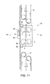
- the weight measuring device 10 of this embodiment has substantially the same structure as the weight measuring device 10 according to the above-described first embodiment, except that the driving mechanism 50 for transmitting a driving force for the conveyor belt 54 to the two drive rollers 2, 4 includes a single pressing mechanism 56.
- the driving mechanism 50 for transmitting a driving force for the conveyor belt 54 to the two drive rollers 2, 4 includes a single pressing mechanism 56.
- the weight measuring device 10 includes a single pressing mechanism 56, which transmits a driving force simultaneously to the two sets of drive rollers 2, 4.
- a single pressing mechanism 56 which transmits a driving force simultaneously to the two sets of drive rollers 2, 4.
- This pressing mechanism 56 is similar to the ones of the first embodiment, and includes a pressing roller 57 pressing the conveyor belt 54 against the outer circumferential surface of the upper and lower rollers 2H, 2L, 4H, 4L of the drive rollers 2, 4, an arm 58 including this pressing roller 57 at its front end, and a motor 59 that lets this arm 58 swing.
- This weight measuring device 10 operates as shown in Fig. 12 . That is to say, in the stand-by state before the mail item M is transported into the conveying unit 42, the pressing mechanism 56 operates in the position shown in Fig. 12(a) , and the conveyor belt 54 is pressed at the same time against the two drive rollers 2, 4. Thus, the drive rollers 2, 4 are rotated at the circumferential speed V, and also the driven rollers 3, 5 rotate at the same circumferential speed.
- the pressing mechanism 56 is operated to the state shown in Fig. 12(b) , and the transmission of the driving force to the drive rollers 2, 4 is stopped. After this, the conveying roller pairs 2, 3, 4, 5 continue to rotate due to their inertial force. In this situation, the mail item M is conveyed by its own inertial force, and its weight is measured together with that of the conveying unit 42.
- the pressing mechanism 56 is set to the state shown in Fig. 12(c) , and the driving force of the conveyor belt 54 is again transmitted to the two drive rollers 2, 4. This operation is continued until there are no more mail items M to be processed.
- the present embodiment it is possible to transmit a driving force from the outside of the conveying unit 42, and the same result as in the above-noted first embodiment can be attained. Moreover, compared to the above-noted first embodiment, since the number of pressing mechanisms 56 is reduced, the configuration of the device can be simplified, and the manufacturing costs of the device can be reduced.
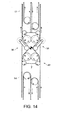
- a pressing roller 57 for transmitting the driving force from one side of the conveying unit 42 is pressed against it from one side, so that the inward force indicated by the arrow F in Fig. 13 acts on the conveying unit 42. That is to say, to cancel this inward force, a method is conceivable, in which a separate pressing mechanism 56 is arranged also on the side of the driven rollers 3, 5, as shown in Fig. 14 .
- a weight measuring device 10 according to a third embodiment of the present invention.
- pressing rollers 57 are pressed directly against the two drive rollers 2, 4, to rotate them.
- the remaining structure is substantially the same as that of the weight measuring device 10 according to the first embodiment.
- like reference numerals are assigned to structural elements having the same functions as in the weight measuring device 10 according to the first embodiment, and their detailed explanation is omitted.
- the weight measuring device 10 includes two driving mechanisms 70 transmitting a driving force to each of the two driving rollers 2, 4.
- These driving mechanisms 70 press the pressing rollers 57 against the outer circumferential surface of the upper and lower rollers 2H, 2L, 4H, 4L of the drive rollers 2, 4, and rotate the pressing rollers 57.
- a driving force is transmitted to the drive rollers 2, 4, the drive rollers 2, 4 are rotated at the circumferential speed V, and also the driven rollers 3, 5 are rotated at the circumferential speed V.
- each of the driving mechanisms 70 includes an arm 58 having a pressing roller 57 at its front end, and a motor 59 for swinging that arm 58.
- the driving mechanisms 70 each include a motor 72 for rotating the pressing roller 57 in the direction of the arrow in the drawing, and a timing belt 74 for transmitting the rotation of the motor 72 to the pressing roller 57.
- This weight measuring device 10 operates as shown in Fig. 16 . That is to say, in the stand-by state before the mail item M is transported into the conveying unit 42, the driving mechanisms 70 are set into the position shown in Fig. 16(a) , and the two pressing rollers 57 are pressed against the corresponding two drive rollers 2, 4. The two pressing rollers 57 are rotated in advance to the predetermined circumferential speed V, before they are pressed against the drive rollers 2, 4.
- the conveying roller pairs 2, 3, 4, 5 continue to rotate due to their inertial force.
- the mail item M is conveyed by its own inertial force, and its weight is measured together with that of the conveying unit 42.
- the arms 58 are swung again to set the driving mechanisms 70 to the state shown in Fig. 16(c) , the pressing rollers 57 contact the drive rollers 2, 4, and the driving force is again transmitted to the two sets of drive rollers 2, 4. This operation is continued until there are no more mail items M left to be processed.
- the present embodiment it is possible to transmit a driving force from the outside of the conveying unit 42, and to achieve the same effects as with the above-described first embodiment.
- a device configuration is adopted in which the pressing rollers 57 are directly pressed against the drive rollers 2, 4, so that it is possible to achieve a higher response speed for switching between transmission and non-transmission of the driving force, and to accommodate high-speed processing of the mail items M.
- a conveyor belt 54 of a separate system is not necessary as a driving force, so that the degree of freedom in the device layout can be increased, and it is possible to freely decide the location where the weight measuring device 10 is set up.
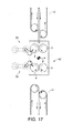
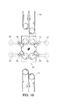
- pressing rollers 57 for transmitting the driving force from one side of the conveying unit 42 are pressed against it from one side, so that the inward force indicated by the arrow F in Fig. 17 acts on the conveying unit 42. That is to say, to cancel this inward force, a method is conceivable, in which a separate driving mechanism 70 is arranged also on the side of the driven rollers 3, 5, as shown in Fig. 18 .
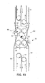
- Fig. 19 shows a modification of the weight measuring device 10 according to the above-noted second embodiment.
- This weight measuring device 10 includes a structure in which a conveying roller pair 4, 5 on the downstream side in the conveying direction of the mail item M is transposed. That is to say, in this modification, the driven roller 5 is arranged on the left of the conveying route 1 in the drawing, and the drive roller 4 is arranged on the right of the conveying route 1 in the drawing.
- this weight measuring device 10 includes a separate pressing mechanism 56 for pressing a conveyor belt 54 of a separate system against the drive roller 4 on the downstream side in conveying direction. Also this pressing mechanism 56 functions like the pressing mechanism 56 corresponding to the drive roller 2, and presses the separate conveyor belt 54 against the drive roller 4.
- Fig. 20 shows a modification of the weight measuring device 10 according to the above-described third embodiment.
- this weight measuring device 10 includes a mechanism, in which the conveying roller pairs 4, 5 on the downstream side in conveying direction of the mail item M are transposed. That is to say, also in this modification, the driven roller 5 is arranged on the left of the conveying route 1 in the drawing, and the drive roller 4 is arranged on the right of the conveying route 1 in the drawing.
- the driving mechanism 70 for transmitting a driving force to the drive roller 4 of the downstream conveying roller pair is arranged on the right side of the conveying unit 42 in the drawing. Also this driving mechanism 70 functions similarly to the driving mechanism 70 for the drive roller 2, and transmits a driving force to the drive roller 4.
- a weight measuring device 10 according to a fourth embodiment of the present invention. Also in the following explanations, like reference numerals are assigned to structural elements having the same functions as the above embodiments, and their detailed explanation is omitted.
- Fig. 21 is a top view of a weight measuring device 10 according to this embodiment.
- Fig. 22 is a cross-sectional view of principal part of the weight measuring device 10 of this embodiment.
- Fig. 23 is a diagram illustrating the drive source of the drive rollers built into the weight measuring device 10 of this embodiment.
- Fig. 24 shows operation diagrams to illustrate the operation of the weight measuring device 10 of the present embodiment.
- the weight measuring device 10 of the present embodiment includes an upstream conveying roller pair 2, 3 arranged upstream in conveying direction of the mail item M, a downstream conveying roller pair 4, 5 arranged downstream in conveying direction, and a base 7 rotatably supporting one end of rotation shafts 2a, 3a, 4a, 5a of the two conveying roller pairs 2, 3, 4, 5.
- the driven roller 3 is arranged on the left side of the conveying route 1 in the drawing and the drive roller 2 is arranged on the right side of the conveying route 1 in the drawing.
- the drive roller 4 is arranged on the left side of the conveying route 1 in the drawing and the driven roller 5 is arranged on the right side of the conveying route 1 in the drawing.
- the two drive rollers 2, 4 each include upper rollers 2H, 4H, and lower rollers 2L, 4L.
- the upper and lower rollers 2H, 2L, 4H, 4L are fixed non-rotatably to the rotation shafts 2a, 4a. That is to say, in the present embodiment, no bearings 6 are provided between the upper and lower rollers 2H, 2L, 4H, 4L and the rotation shafts 2a, 4a. In other words, the two drive rollers 2, 4 rotate by rotating the rotation shafts 2a, 4a.
- the base ends of the rotation shafts 2a, 4a of the drive rollers 2, 4 pass through the base 7 and extend downward from it.
- a driving source 80 for rotating the drive rollers 2, 4 is provided at the base end of the rotation shafts 2a, 4a for each of the drive rollers 2, 4.
- a bearing 82 is provided between each of the rotation shafts 2a, 4a and the base 7. These bearings 82 are thrust bearings that support the weight of the drive rollers 2, 4 and rotatably support the drive rollers 2, 4.
- a driving source 80 of the present embodiment include a plurality of impeller blades 84 subjected to an air stream, for example, and rotating the rotation shaft 2a, a chamber 86 in which the plurality of impeller blades 84 are accommodated rotatably and in a non-contacting manner and in which an airstream is generated in a circumferential direction, and an airstream generating device 88, such as a pump not shown in the drawing.
- the plurality of impeller blades 84 may be rectangular plates protruding radially from the rotation shaft 2a. Since the chamber 86 accommodates the plurality of impeller blades 84 in a non-contacting manner, it is separate from the conveying unit 42.
- the airflow generating device 88 is connected to the controller 60, and the rotation speed of the drive roller 2 is controlled by controlling the amount of air fed into the chamber 86. It should be noted that only the driving source 80 of the drive roller 2 is shown in the drawing, but the same driving source 80 is also attached to the drive roller 4.
- the fluid rotating the impeller blades 84 is not limited to air and may also be water or oil.
- the weight measuring device 10 having this structure operates as shown in Fig. 24 .
- the controller 60 operates the airstream generating device 88, and the two drive rollers 2, 4 are rotated at the circumferential speed V.
- the driving source 80 of the present embodiment rotates the rotation shafts 2a, 4a by pressing against the impeller blades 84 with air, so that also when a driving force is applied to the drive rollers 2, 4, hardly any vibration is transmitted to the rotation shafts 2a, 4a.
- the controller 60 obtains the timing at which the rear edge in conveying direction of the next mail item M that is transported into the weight measuring device 10 leaves the upstream conveying portion 12, and stops the transmission of driving force to the drive rollers 2, 4 at the above-described suitable timing. In this situation, the drive rollers 2, 4 rotate freely. It should be noted that the upper and lower rollers 2H, 2L, 4H, 4L of the drive rollers 2, 4 each have a flywheel 22, so that the drive rollers 2, 4 continue to rotate, even when the transmission of the driving force is stopped.
- the controller 60 measures the weight of the conveying unit 42 with the weight sensor 40, and calculates the weight of the mail item M that is passing through the conveying unit 42 with the arithmetic portion 64. This state is shown in Fig. 24(b) .
- the controller 60 again applies a driving force to the two drive rollers 2, 4, as shown in Fig. 24(c) , and rotates the drive rollers 2, 4 at the circumferential speed V.
- a driving force to measure the weight of the mail item M, so that there is no problem in transmitting a driving force as long as the measurement of the weight of the mail item M has been finished.
- an airflow acts on the impeller blades 84 attached to the rotation shafts 2a, 4 of the drive rollers 2, 4, to transmit the driving force, so that hardly any vibrations are transmitted to the drive rollers 2, 4, even in a state in which the driving force is applied.
- the transmission of the driving force is stopped when the weight of the mail item M is measured, but it is no problem to perform the weight measurement while the driving force is still being applied.
- Fig. 25 is a diagrammatic view of a driving source 90 of a drive roller 2 built into a weight measuring device 10 according to a fifth embodiment of the present invention.
- This driving source 90 is provided for each of the rotation shafts 2a, 4a of the drive rollers 2, 4, but here, only the drive source 90 provided for the drive roller 2 is explained as a representative example. Also in the following explanations, like reference numerals are assigned to structural elements having the same functions as in the fourth embodiment, and their detailed explanation is omitted.
- the driving source 90 of the present embodiment includes a magnet 92 fixed to a base portion of the rotation shaft 2a extending through the base 7, a coil 94 arranged around this magnet in a non-contacting manner, and a current supplying device 96 for letting a current flow through this coil 94.
- a coil it is also possible to attach a coil to the rotation shaft 2a and provide a magnet outside it.
- the controller 60 controls the current supplying device 96 to control the current amount flowing through the coil 94, and thus controls the rotation speed of the rotation shaft 2a, that is, the circumferential speed of the drive roller 2. That is to say, the controller 60 controls the current flowing through the coil 94 to rotate the drive roller 2 at the circumferential speed V
- a bearing 98 as shown in Fig. 22 is provided on the rotation shaft 2a of the drive roller 2.
- This bearing 98 has such a structure that, when a weight acts on the rotation shaft 2a from above in the drawing, it yields without supporting this weight. More specifically, the upper side in the drawing of a groove that is formed on the outer circumference of a cylindrical body 98a on the side of the rotation shaft 2a is open, and when this cylindrical body 98a moves downward in the drawing, the groove does not constrain the spheres 98b. Conversely, when the cylindrical body 98a is moved upward in the drawing, the groove of the cylindrical body 98a is engaged by the spheres, and the movement of the rotation shaft 2a is stopped.
- the weight measuring device 10 with this configuration operates as shown in Fig. 24 .
- the controller 60 controls the current supplying device 96 to let a current flow through the coil 94, rotating the two drive rollers 2, 4 at the circumferential speed V.
- the driving source 90 of the present embodiment rotates the rotation shafts 2a, 4a by electromagnetic force, so that also when a driving force is applied to the drive rollers 2, 4, there is hardly any vibration transmitted to the rotation shafts 2a, 4a.
- the controller 60 After this, based on an output signal from the timing sensor 62, the controller 60 obtains the timing at which the rear edge in conveying direction of the next mail item M that is transported into the weight measuring device 10 leaves the upstream conveying portion 12, and stops the transmission of driving force to the drive rollers 2, 4 at the above-described suitable timing. That is to say, in this situation, the controller 60 controls the current supply device 96 to stop the supply of current to the coil 94.
- the drive rollers 2, 4 rotate freely.
- the upper and lower rollers 2H, 2L, 4H, 4L of the drive rollers 2, 4 each have a flywheel 22, so that the drive rollers 2, 4 continue to rotate due to their own inertial force, even when the transmission of the driving force is stopped.
- the controller 60 measures the weight of the conveying unit 42 with the weight sensor 40, and calculates the weight of the mail item M that is passing through the conveying unit 42 with the arithmetic portion 64. This state is shown in Fig. 24(b) .
- the controller 60 again applies a driving force to the two drive rollers 2, 4, as shown in Fig. 24(c) , and rotates the drive rollers 2, 4 at the circumferential speed V.
- a driving force to measure the weight of the mail item M, so that there is no problem in transmitting a driving force as long as the measurement of the weight of the mail item M has been finished.
- the driving force is transmitted by applying an electromagnetic force to the magnets 92 attached to the rotation shafts 2a, 4a of the drive rollers 2, 4, so that vibrations are hardly transmitted to the drive rollers 2, 4, even in a state in which the driving force is applied.
- flywheel 22 is built into each of the drive rollers 2, 4, but there is no limitation to this, and it is also possible to build flywheels 22 only into the driven rollers 3, 5, or to build flywheels 22 into all rollers. Furthermore, configurations in which the driving source for applying a driving force is provided separately from the conveying unit, and configurations in which a portion of the driving source remains in the conveying unit are possible, as long as the effect of the present working example is attained.
- the weight of a mail item M serving as a sheet-like article is measured, but the sheet-like articles whose weight is to be measured are not limited to mail items.
Landscapes
- Physics & Mathematics (AREA)
- Mathematical Physics (AREA)
- Engineering & Computer Science (AREA)
- Theoretical Computer Science (AREA)
- General Physics & Mathematics (AREA)
- Sorting Of Articles (AREA)
- Delivering By Means Of Belts And Rollers (AREA)
Abstract
A weight measuring device for measuring the weight of a sheet-like article, comprising: a conveying unit that is arranged at a conveying route to convey the sheet-like article to be measured, the conveying unit being adapted to rotate while contacting the sheet-like article without being subjected to a driving force from outside after receiving the sheet-like article from the conveying route, and transporting the sheet-like article in its rotation direction while supporting the weight of the sheet-like article; and a scale to measure the weight of the conveying unit in a state in which the conveying unit supports the weight of the sheet-like article and transports the sheet-like article.
Description
- This application is based upon and claims the benefit of priority from Japanese Patent Application No.
P2010-119758, filed on May 25th, 2010 - Embodiments of a present specification are generally related with devices for measuring the weight of a sheet-like article, such as a mail item, a sheet processing device including such a weight measuring device, and a method for measuring the weight of a sheet-like article.
- Ordinarily, in mail processing machines, the weight of a mail item is measured while the mail item is being conveyed, in order to judge whether charge imprints, such as postage stamps, attached to the mail item correspond to the proper postage. As a method to measure the weight of the mail item while it is being conveyed, it is known to measure the weight of an entire conveying device arranged along a conveying route, while the mail item passes through the conveying device, for example.
-
Patent Document 1JP 2002-263583A - However, if the weight of the mail item is measured by measuring the weight of the conveying device while the mail item passes through it, and the ratio of the weight of the mail item to the weight of the conveying device alone is small, then the weight of the mail item cannot be measured accurately. That is to say, if the conveying device is heavy, then the precision of the weight measurement of the mail item decreases accordingly. Ordinarily, the conveying device is provided with a mechanism for conveying the mail item, that is, conveying rollers and a motor, so that the weight of the conveying device is very heavy compared to the weight of the mail item.
- Also, during the conveying of the mail item, a conveying force is applied to the conveying device to the mail item, so that the application of this conveying force may have an adverse influence on the weight measurement result. That is to say, by applying a conveying force on the mail item, the entire conveying device may be subject to vibrations or stress, so that the measurement result is not stable. In particular if the weight of the mail item is measured while the mail item is being conveyed at high speed, it is very difficult to eliminate vibrations and stress transmitted to the conveying device from the driving source, such as a motor.
- It is an object of the present invention to provide a weight measuring device, a sheet processing apparatus including such a weight measuring device, and a weight measuring method, with which the weight of a sheet-like article can be accurately measured.
- To attain this object, a weight measuring device in accordance with one embodiment of the present invention includes a conveying unit that is arranged at (or along) a conveying route to convey the sheet-like article to be measured, the conveying unit being adapted to rotate while contacting the sheet-like article without being subjected to a driving force from outside after receiving the sheet-like article from the conveying route, and transporting the sheet-like article in its rotation direction while supporting the weight of the sheet-like article; and a scale to measure the weight of the conveying unit in a state in which the conveying unit supports the weight of the sheet-like article and transports the sheet-like article.
-
-
Fig. 1 is a block diagram showing the configuration of a mail item sorting / aligning / stamping apparatus, which serves as an example of a sheet processing apparatus in accordance with an embodiment of the present invention; -
Fig. 2 is a diagrammatic top view of the principal parts of a weight measuring device in accordance with a first embodiment of the present invention, which is built into a mechanical detection portion of the stamping apparatus inFig. 1 ; -
Fig. 3 is a side view of the weight measuring device inFig. 2 , taken from the arrow direction III; -
Fig. 4 is a sectional view of a conveying roller pair inFig. 3 , taken along the line IV-IV; -
Fig. 5 is a sectional view of a drive roller inFig. 4 , taken along the line V-V; -
Fig. 6 is a block diagram of a control system controlling the operation of the weight measuring device inFig. 2 ; -
Fig. 7 shows operation diagrams to illustrate the operation of the weight measuring device inFig. 2 ; -
Fig. 8 is a flowchart illustrating the operation of the weight measuring device inFig. 2 in conjunction withFig. 7 ; -
Fig. 9 is a diagrammatic top view illustrating the inward force acting on the weight measuring device inFig. 2 ; -
Fig. 10 is a diagrammatic top view showing an example of a configuration for cancelling the inward force illustrated inFig. 9 ; -
Fig. 11 is a diagrammatic top view showing the principal parts of a weight measuring device according to a second embodiment of the present invention; -
Fig. 12 shows operation diagrams illustrating the operation of the weight measuring device inFig. 11 ; -
Fig. 13 is a diagrammatic top view illustrating the inward force acting on the weight measuring device inFig. 11 ; -
Fig. 14 is a diagrammatic top view showing an example of a configuration for cancelling the inward force illustrated inFig. 13 ; -
Fig. 15 is a diagrammatic top view showing the principal parts of a weight measuring device according to a third embodiment of the present invention; -
Fig. 16 shows operation diagrams illustrating the operation of the weight measuring device inFig. 15 ; -
Fig. 17 is a diagrammatic top view illustrating the inward force acting on the weight measuring device inFig. 15 ; -
Fig. 18 is a diagrammatic top view showing an example of a configuration for cancelling the inward force illustrated inFig. 17 ; -
Fig. 19 is a diagrammatic top view showing a modification of the weight measuring device inFig. 11 ; -
Fig. 20 is a diagrammatic top view showing a modification of the weight measuring device inFig. 15 ; -
Fig. 21 is a diagrammatic top view of a weight measuring device according to a fourth embodiment of the present invention; -
Fig. 22 is a cross-sectional view of the weight measuring device inFig. 21 , taken along line XXII-XXII; -
Fig. 23 is a diagram illustrating the driving portion of a drive roller of the weight measuring device inFig. 21 ; -
Fig. 24 shows operation diagrams illustrating the operation of the weight measuring device inFig. 21 ; and -
Fig. 25 is a diagrammatic view of a driving source of a drive roller built into a weight measuring device according to a fifth embodiment of the present invention. - Referring to the accompanying drawings, the following is a detailed description of embodiments of the present invention.
Fig. 1 shows a diagrammatic block diagram of a mail item sorting / aligning / stamping apparatus 100 (referred to in the following simply as "stamping apparatus 100"), which serves as an example of a sheet processing apparatus in accordance with the present invention. - The
stamping apparatus 100 includes asupply portion 101, amechanical detection portion 102, anOCR scanner portion 103, atwisting portion 104, aswitchback portion 105, astamping portion 106, and a sorting /stacking portion 107, arranged in the conveying direction of the mail item M (sheet-like article). Furthermore, thestamping apparatus 100 includes aconveying portion 108, which conveys a mail item M through these units. Thestamping apparatus 100 also includes an operation panel not shown in the drawings, with which commands for various operations can be given to the apparatus, with which the operation mode can be switched and which displays warnings messages and the like. - The
supply portion 101 receives for example a batch of standardized mail items M whose thickness, length in conveying direction, width in a direction perpendicular to the conveying direction and weight lie within a predetermined range, takes out these mail items one by one and supplies them to the downstream processing units. Theconveying portion 108 includes aconveying route 1 which conveys the mail items M supplied to it through the followingprocessing units 102 to 107. - The
mechanical detection portion 102 detects metal, foreign items and hard items contained in the mail items M that are conveyed by theconveying portion 108 along the conveyingroute 1, detects double take-outs (that is, overlapped feeding) of mail items M as well as short gaps, and rejects mail items M that are judged to be not processable by thedownstream processing units 103 to 107 to a rejection sheet stacker, which is not shown in the drawings. It should be noted that themechanical detection portion 102 includes aweight measuring device 10, described later, which measures the weight of the conveyed mail items M. - The
mechanical detection portion 102 furthermore detects in advance the length in conveying direction or the width of a mail item M before it reaches theweight measuring device 10, detects the passing of the front edge and the passing of the rear edge of the mail item M with atiming sensor 62 explained later, and obtains, in advance, information relating to the conveying position of this mail item M. - Moreover, the
mechanical detection portion 102 measures the weight of the mail item M by letting theweight measuring device 10 operate as described below, based on the length, width and conveying position of the mail item M, and rejects any mail item M that is judged to have an abnormal weight by theweight measuring device 10 to a rejection sheet stacker not shown in the drawings. - The
OCR scanner portion 103 optically reads the surface of the mail item M, converting it into an electric signal, and obtains sorting information, such as the postal code or the address written on the mail item M, as an image. Moreover, theOCR scanner portion 103 detects the presence and the position of any postage stamps (this also includes any charge imprints including fee indicators or the like) attached to the mail item M. Since the orientation (front/rear, top/bottom) of the mail item M supplied through thesupply portion 101 is not the same for all mail items M, theOCR scanner portion 103 includes at least two scanner units to read both sides of the mail items M. - The
twisting portion 104 includes a twisting path (not shown in the drawings) that conveys the mail items M while twisting them by 180° around their central axis, which extends along the conveying direction of the mail items M. That is to say, thetwisting portion 104 flips over the mail items M without changing their conveying direction. Thetwisting portion 104 also includes a detour diverting path (straight path) (not shown in the drawings) for diverting mail items M transported into it without transporting them to the twisting path. - The
switchback portion 105 includes two switchback mechanisms (not shown in the drawings) that reverse the conveying direction of the mail items M by receiving conveyed mail items M and outputting them in the opposite direction. Like thetwisting portion 104 described above, also theswitchback portion 105 includes a diverting path (straight path) for circumventing the two switchback mechanisms. - The
stamping portion 106 includes a stamping hub not shown in the drawing, which rotates while contacting one surface of the conveyed mail item M. Thestamping portion 106 stamps a cancellation mark while rotating this stamping hub in contact with the position of the postage stamp. In the present embodiment, all mail items M conveyed to thestamping portion 106 are aligned with respect to front/rear and top/bottom by passing through thetwisting portion 104 and theswitchback portion 105, so that the stamping hub is provided only on one side of the conveyingroute 1. - The sorting /
stacking portion 107 sorts and stacks mail items M to a predetermined sorting position in accordance with the sorting information detected with theOCR scanner portion 103. Moreover, the sorting / stackingportion 107 includes a rejection sheet stacker not shown in the drawings, which prohibits the stamping with the stampingportion 106, of mail items M that are temporarily held in theswitchback portion 105 and then transported forward, and to which rejected mail items are sent. - The
stamping apparatus 100 with this configuration judges whether the postage mark, such as a stamp, read from the mail item M with theOCR scanner portion 103 corresponds to the proper postage in view of the weight of the mail item M as measured with the above-notedweight measuring device 10, and rejects mail items M that are judged to have insufficient postage, without stamping a cancellation mark on them with the stampingportion 106. -
Fig. 2 is a diagrammatic top view of the principal parts of aweight measuring device 10 in accordance with a first embodiment of the present invention, which measures the weight of a mail item M passing by themechanical detection portion 102 on the conveyingroute 1.Fig. 3 is a side view of theweight measuring device 10 inFig. 2 , seen from the arrow direction III.Fig. 4 is a sectional view ofupper rollers roller pair Fig. 3 , taken along the line IV-IV.Fig. 5 is a sectional view of thedrive roller 2 inFig. 4 , taken at the line V-V along itsrotation shaft 2a. - Referring to these
Figs. 2 to 5 , the following is an explanation of the configuration of theweight measuring device 10 according to the first embodiment of the present invention.
Theweight measuring device 10 of this embodiment can successively measure the weight of a plurality of mail items M that are conveyed continuously at comparatively high speed on the conveyingroute 1, without stopping or decelerating the conveyance of the mail items M. It should be noted that in the present embodiment, the mail items M passing the mechanical detection portion 102 (that is, the weight measuring device 10) are conveyed in an upright orientation on the conveyingroute 1. That is to say, the conveying plane of the mail items M passing theweight measuring device 10 extends in the vertical direction. - As shown in
Fig. 2 , theweight measuring device 10 includes two sets of conveying roller pairs 2, 3, 4, and 5 that forward mail items M transported in an upright position from thesupply portion 101 on the conveyingroute 1 in the arrow direction T shown in the drawing. As described later, immediately prior to measuring the mail items M, a driving force is applied to these two sets of conveying roller pairs 2, 3, 4, and 5, rotating them at the same circumferential speed as the conveying speed V of the mail items M. It should be noted that, when measuring the weight of the mail items M, the two sets of conveying roller pairs 2, 3, 4, and 5 contact the mail items M, which are conveyed in the arrow direction T at a predetermined speed V, so that their rotation follows the mail items M, and they do not exert a conveying force on the mail items M. In another words, theweight measuring device 10 is not forced by a driving force from outside after the mail items M is received. - However, the mail items M transported at the predetermined speed pass through the
weight measuring device 10 by being forwarded by the conveying roller pairs 2, 3, 4, 5 rotating at the same circumferential speed as well as due to their own inertia, so that after the mail items M have passed through theweight measuring device 10, the conveying speed V of the mail items M is substantially sustained. - On the upstream side of the
weight measuring device 10 in the conveying direction T of the mail items M, anupstream conveying portion 12 is provided, which transports the mail items M conveyed from thesupply portion 101 at the conveying speed V into theweight measuring device 10. Moreover, on the downstream side of theweight measuring device 10 in the conveying direction T of the mail items M, a downstream conveyingportion 14 is provided, which receives the mail items M that have passed through theweight measuring device 10 and conveys them at the conveying speed V. - As noted above, the
weight measuring device 10 does not apply a conveying force to the mail items M while they pass through it, so that the mail items M passing through theweight measuring device 10 are basically conveyed in a free (unconstrained) state. However, the downstream conveyingportion 14 conveys the mail items M at the same conveying speed V as theupstream conveying portion 12, so that even if the conveying speed of the mail items M has been slightly slowed down when passing through theweight measuring apparatus 10, the conveying speed of the mail items M is returned to the original speed V by the downstream conveyingportion 14. - A predetermined gap is provided between the
weight measuring device 10 and theupstream conveying portion 12, as well as between theweight measuring device 10 and the downstream conveyingportion 14. These upstream and downstream gaps of theweight measuring apparatus 10 are provided in order to attain a state in which the mail items M are held only by the two sets of conveying roller pairs 2, 3, 4, 5, as shown inFig. 2 . The gaps on both sides have a predetermined length, so that mail items M can be handled whose length in the conveying direction T is longer than the length of the mail item M shown in the drawing. - The conveying
roller pair drive roller 2 to which a driving force can be selectively applied by a driving unit explained later, and a drivenroller 3 whose rotation follows that of thedrive roller 2, the conveyingroute 1 being arranged between thedrive roller 2 and the drivenroller 3. The conveyingroller pair drive roller 4 to which a driving force can be selectively applied by a driving unit explained later, and a drivenroller 5 whose rotation follows that of thedrive roller 4, the conveyingroute 1 being arranged between thedrive roller 4 and the drivenroller 5. - The two
drive rollers route 1 in the drawing, spaced apart from one another in the transport direction T, whereas the drivenrollers route 1 in the drawing in opposition to and contacting thedrive rollers route 1 arranged between them. - As shown in
Fig. 3 , thedrive rollers rollers upper rollers lower rollers respective rotation shafts Fig. 3 , only the two drivenrollers upper rollers lower rollers rotation shafts Figs. 4 and 5 ). - That is to say, the bottom ends of the
rotation shafts rollers base 7 and they are each supported by thebase 7 at least in a canterlever-like manner. Moreover, theupper rollers lower rollers rotation shafts base 7 extends substantially horizontally, and the fourrotation shafts - The distance between the
rotation shafts roller pair upper roller 2H and the outer circumferential surface of theupper roller 3H contact each other on the conveyingroute 1, and the outer circumferential surface of thelower roller 2L and the outer circumferential surface of the lower roller 3L contact each other on the conveyingroute 1. Moreover, the distance between therotation shafts 4a, 5a of the downstream conveyingroller pair route 1, and the outer circumferential surface of thelower roller 4L and the outer circumferential surface of the lower roller 5L contact each other on the conveyingroute 1. - Referring to
Figs. 4 and 5 , the following is a detailed explanation of the structure of upper and lower rollers of thedrive rollers rollers upper roller 2H of thedrive roller 2 on the upstream side and theupper roller 3H of the drivenroller 3 on the upstream side. - The
lower roller 2L of theupstream drive roller 2 and the upper andlower rollers 4H and 4L of thedownstream drive roller 4 have the same structure as theupper roller 2H of theupstream drive roller 2, which is explained here. Also, the lower roller 3L of the upstream drivenroller 3 and the upper and lower rollers 5H, 5L of the downstream drivenroller 5 have the same structure as theupper roller 3H of the upstream drivenroller 3, which is explained here. Thus, a detailed explanation of these upper andlower rollers - As shown in
Figs. 4 and 5 , theupper roller 2H of thedrive roller 2 is rotatably attached via thebearing 6 to therotation shaft 2a. Theupper roller 2H includes aflywheel 22, which is provided on the outside of thebearing 6, and arubber layer 24, which is provided on the outside of theflywheel 22. Therubber layer 24 of thisupper roller 2H is slightly deformable, but is hardly deformed at all when a mail item M collides with it. It is preferable that theflywheel 22 is made of a relatively heavy metal, such as copper or iron, in order to make the moment of inertia of theupper roller 2H relatively high. - Moreover, the
upper roller 3H of the drivenroller 3 is attached rotatably to therotation shaft 3a via thebearing 6, as shown inFig. 4 . Thisupper roller 3H includes a core metal 32 that is provided on the outside of thebearing 6, asponge layer 34 that is provided on the outside of the core metal 32, and arubber layer 36 that is provided on the outside of thesponge layer 34. Thesponge layer 34 of thisupper roller 3H is highly deformable, so that it can be considerably deformed when colliding with a mail item M. - That is to say, when a mail item M is inserted between the
drive roller 2 and the drivenroller 3, then the upper andlower rollers 3H and 3L of the drivenroller 3 are deformed, absorbing the change of thickness of the mail item M. In this situation, if the thickness of the mail items M varies along the rotation shaft direction of the rollers, then theupper roller 3H and the lower roller 3L, which can rotate independently from each other with respect to therotation shaft 3a, are deformed by different deformation amounts, thus preventing skewing of the mail item M. - As shown in
Fig. 5 , theflywheels 22 are built into the upper andlower rollers drive roller 2. Eachflywheel 22 is formed in such a shape that its volume is concentrated near its outercircumferential portion 22a, and is made of a comparatively heavy metal (for example copper or iron), whereas it is made thinner at a position near its rotation center. Thus, when a mail item M contacts the upper andlower rollers drive roller 2 including theflywheels 22, the inertial force causing it to keep rotating is large, so that the rotation speed decreases only little. - Returning to
Fig. 3 , theweight measuring device 10 includes aweight sensor 40 that is attached to the lower side of thebase 7. Theweight sensor 40 of this embodiment is a six-axis force sensor. It is also possible to use a force sensor that is sensitive on three axes as the weight sensor. It should be noted that a force sensor as disclosed inJP 2010-230631A - The
weight sensor 40 is arranged at the center of gravity of thebase 7, which supports therotation shafts weight sensor 40 measures the weight of an overall conveyingunit 42 including the two sets of conveying roller pairs 2, 3, 4, 5 and thebase 7. - That is to say, as shown in
Fig. 2 , theweight sensor 40 measures the weight of the overall conveyingunit 42 in a state after the conveyed mail item M leaves theupstream conveying portion 12 and before it is transported to the downstream conveyingportion 14. Thus, theweight sensor 40 measures the weight of the mail item M while it is being conveyed. That is to say, the weight of the mail item M can be calculated by subtracting the weight of the conveyingunit 42 when it does not convey a mail item M. - In the present embodiment, the conveying
unit 42 with which theweight sensor 40 measures the weight has a simple structure in which the upstream conveyingroller pair roller pair base 7, so that the apparatus can be made lighter than conventional conveying apparatuses. That is to say, there is no driving source, such as a motor, for applying a conveying force to the mail items M mounted to this conveyingunit 42. Therefore, the ratio of the weight of the mail item M to the weight of the conveyingunit 42 can be made large, and the precision with which the weight of the mail item M is measured can be increased. - Returning to
Fig. 2 , theweight measuring device 10 includes adriving mechanism 50 for applying a driving force to thedrive rollers Fig. 2 , thedriving mechanism 50 includes aconveyor belt 54 of a separate system, which is driven at a predetermined speed by tworollers 52, and twopressing mechanisms 56 that press thisconveyor belt 54 as a driving source against the two sets ofdrive rollers pressing mechanisms 56 each include apressing roller 57, anarm 58 to the front end of which thepressing roller 57 is rotatively attached, and amotor 59 for turning thisarm 58. - When the
motors 59 of thepressing mechanisms 56 rotate, thearms 58 are swung and theconveyor belt 54 is pressed against thedrive roller 2 by thepressing rollers 57 attached to the front ends of thearms 58. Thus, the driving force of theconveyor belt 54 is transmitted to thedrive rollers - In the present embodiment, the
drive rollers upper rollers 2H, 4H and theirlower rollers pressing mechanisms 56 are provided for thedrive rollers conveyor belts 54, corresponding to the upper andlower rollers pressing mechanism 56 shown in the drawings is explained in the following. -
Fig. 6 is a block diagram of a control system controlling the operation of theweight measuring device 10 having the above structure.
Atiming sensor 62, aweight sensor 40, anarithmetic portion 64 and themotors 59 of thepressing mechanisms 56 are connected to acontroller 60 of theweight measuring device 10. Thetiming sensor 62 is arranged further to the upstream side in conveying direction of the mail items M than theweight measuring device 10, and detects the passage of a front edge and a rear edge of a mail item M at a predetermined position. Thistiming sensor 62 includes a light-emitting portion and a light-receiving portion, not shown in the drawings, that oppose each other across the conveyingroute 1. - Based on the weight of the conveying
unit 42 that has been detected by thecontroller 60 with theweight sensor 40, thearithmetic portion 64 calculates the weight of the mail item M that passes the conveyingunit 42. That is to say, thearithmetic portion 64 calculates the weight of the mail item M by subtracting the empty weight of the conveyingunit 42, which has been measured in advance, from the weight of the conveyingunit 42 while it is conveying the mail item M. - Referring to
Figs. 7 and8 , the following is an explanation of the operation of thecontroller 60 of theweight measuring device 10 having the above-described structure.Figs. 7(a) to 7(c) are operation diagrams to illustrate the operation of theweight measuring device 10. Also,Fig. 8 is a flowchart to illustrate the operation of theweight measuring device 10 in conjunction withFig. 7 . - Before the mail item M is transported into the
weight measuring device 10, thecontroller 60 of theweight measuring device 10 is first in a stand-by state, in which it operates thedriving mechanism 50 as shown inFig. 7(a) , applies a driving force to the twodrive rollers unit 42, and causes the two sets of conveying roller pairs 2, 3, 4, 5 to rotate at the predetermined circumferential speed V (seeFig. 8 , Step 1). That is to say, thecontroller 60 starts up themotor 59 of each of thepressing mechanisms 56 of thedriving mechanism 50, puts thepressing rollers 57 into the position ofFig. 7(a) , and presses theconveyor belt 54 of the separate system against the outer circumferential surface of the twodrive rollers - The
conveyor belt 54 is a conveyor belt of a separate system that runs within themechanical detection portion 102, and runs at the same speed V as the conveyor belt of the upstream conveyingportion 12 and the downstream conveyingportion 14. Therefore, atStep 1 inFig. 8 , thedrive rollers conveyor belt 54 running at the speed V also rotate at the same circumferential speed V. It should be noted that when the twodrive rollers rollers - After this, the
controller 60 monitors the output of thetiming sensor 62, and detects the passage of the front edge and the passage of the rear edge in conveying direction of the mail item M that is transported next into theweight measuring device 10. At this time, thecontroller 60 detects the length in the conveying direction of the mail item M based on the time period from the dark state to the light state of thetiming sensor 62 and the conveying speed V of the mail item M, and detects the passage of the rear edge of the mail item M based on the fact that thetiming sensor 62 has gone from its dark state to the light state (Step 2). - After the
controller 60 has detected the passage of the rear edge in conveying direction of the mail item M in Step 2 (Step 2: YES), a timer not shown in the drawings is set, and the timing at which the rear edge in conveying direction of the mail item M leaves theupstream conveying portion 12 is obtained. Then, after the rear edge in conveying direction of the mail item M has left the upstream conveyingportion 12, thecontroller 60 stops the transmission of the driving force to thedrive rollers controller 60 starts up themotor 59 of each of thepressing mechanisms 56 of thedriving mechanism 50, and puts thepressing rollers 57 into the position ofFig. 7(b) . - What is referred to here as "suitable timing" means a timing after the transmission of the driving force to the
drive rollers unit 42 have attenuated and are substantially gone, so that a more accurate weight measurement becomes possible. It should be noted that in this case, the timing at which the transmission of the driving force inStep 3 is stopped may also be a timing prior to when the rear edge in the conveying direction of the mail item M has left the upstream conveyingportion 12. - In this state, the mail item M passes the conveying
unit 42 in a state in which it is free, due to its own inertial force. At this time, no conveying force is applied by the conveyingunit 42 to the mail item M, so that until the front edge in conveying direction of the mail item M is passed on to the downstream conveyingportion 14, the conveying speed of the mail item M is gradually decelerated. However, in this situation, the two sets of conveying roller pairs 2, 3, 4, 5 rotate at a predetermined speed V due their own inertial force, so that there is no risk that a force is exerted that might impede the conveying of the mail item M at least with regard to the conveying roller pairs. - Rather, the two
drive rollers flywheels 22, so that it is conceivable that the proportion of the speed decrease becomes lower for the upper andlower rollers drive rollers drive rollers - In any case, after the transmission of the driving force has ceased in
Step 3, thecontroller 60 begins the weight measurement of the conveyingunit 42 at the above-described suitable timing (Step 4). In this situation, thecontroller 60 detects the weight of the conveyingunit 42 while it is conveying the mail item M with the arithmetic portion with theweight sensor 40, and calculates, with thearithmetic portion 64, the weight of the mail item M by subtracting from this the weight of the conveyingunit 42 that has been detected in advance. - When the weight measurement of the mail item M has finished (Step 5: YES), the
controller 60 restarts the transmission of the driving force to the twodrive rollers Step 1, thecontroller 60 starts up themotor 59 of each of thepressing mechanisms 56 of thedriving mechanism 50, puts thepressing rollers 57 into the situation shown inFig. 7(c) , and presses theconveyor belt 54 against the outer circumference of the two sets ofdrive rollers - It should be noted that the timing when the transmission of the driving force to the
drive rollers Step 6 does not necessarily have to be a timing after the mail item M has been completely handed over to the downstream conveyingportion 14, but may also be a timing that is slightly before that, as long as the weight measurement of the mail item M has been completed. That is to say, in the present embodiment, the object is to measure the weight of the mail item M with high precision while it is being conveyed, so that as long as the weight measurement has finished, there is no problem in applying an external force to the mail item M. - The
controller 60 continues the processing ofStep 1 to Step 6 as described above until there are no more mail items M to be processed, and at the time when there are no more mail items M to be processed (Step 7: NO), the measurement operation is finished. - In this manner, with the present embodiment, since there is no driving source, such as a motor, mounted to the conveying
unit 42, the conveyingunit 42 can be made correspondingly lighter. Furthermore, with the present embodiment, therotation shafts unit 42 are fixed to thebase 7, and the upper andlower rollers 3H, 3L, 5H, 5L of the drivenrollers unit 42 can be made correspondingly lighter. - Furthermore, with the present embodiment, the
rotation shafts base 7 in a cantilever state, so that a frame for holding both ends of the rotation axes is not necessary, and the conveyingunit 42 can be made correspondingly lighter. Furthermore, with the present embodiment, the drivenrollers unit 42 can be made correspondingly lighter. - By reducing the weight of the conveying
unit 42, as in the present embodiment, the ratio of the weight of the mail item M to that of the conveyingunit 42 can be made relatively large, so that the weight of the mail item M can be measured with greater precision. Moreover, by reducing the weight of the conveyingunit 42, the frequency response can be made faster, and weight measurements with a high response speed and high resolution become possible. - Furthermore, with the present embodiment, immediately before measuring the weight of the mail item M passing through the conveying
unit 42, thepressing rollers 57 are retracted to the position shown inFig. 7(b) , so that no driving force is transmitted to the conveying roller pairs 2, 3, 4, 5. Therefore, no external force is applied to the conveyingunit 42 during the weight measurement, so that it can be prevented that undesired vibrations are transmitted to the conveyingunit 42 and have an adverse influence on the weight measurement. - It should be noted that in this case, the mail item M passes the conveying
unit 42 while being supported by the conveying roller pairs 2, 3, 4, 5 that are rotated in advance at the predetermined circumferential speed V. At this time, since thedrive rollers unit 42 with its own inertial force is about to decrease, it can be expected that they assist the conveyance, so that the speed decrease can be mitigated. - Furthermore, with the present embodiment, a
conveyor belt 54 of a separate system that was there to begin with is used as the driving source for rotating the conveying roller pairs 2, 3, 4, 5 of the conveyingunit 42. Therefore, there is no need to provide a dedicated driving source for the conveyingunit 42, and the manufacturing costs of the apparatus can be reduced correspondingly. - Furthermore, with the present embodiment, to apply a driving force to the
drive rollers conveyor belt 54 is elastically pressed against the upper andlower rollers unit 42 when contacting or removing thedriving mechanism 50 to or from thedrive rollers unit 42 vibrates during the weight measurement of the mail items M, the weight of the mail items M can be measured correspondingly more accurately, and it is possible to increase the measurement precision. - However, when the
conveyor belt 54 is pressed against thedrive rollers unit 42, as in the present embodiment, then, as shown inFig. 9 , an inward force in the direction of the arrow F shown in the drawing acts on thepivot axis 44 of theweight sensor 40 on which the conveyingunit 42 is supported. Such an inward force occurs every time thepressing mechanism 56 of thedriving mechanism 50 operates and can result in a force that lets the conveyingunit 42 swing. - However, this inward force can be measured using a six-axis force sensor as the weight sensor as in the present embodiment, and does not prevent an accurate weight measurement of the mail items M. However, if a six-axis force sensor is not used as the weight sensor, then it is possible that such an inward force has an adverse influence on the weight measurement.
- Therefore, a method for preventing this inward force is conceivable, in which two
pressing mechanisms 56 are provided also on the side of the drivenrollers Fig. 10 . In other words, as shown inFig. 10 , by providing a plurality ofpressing mechanisms 56 such that the external force applied to thepivot axis 44 of theweight sensor 40 is canceled, it is possible to prevent the above-described inward force, and it is possible to use for example an electromagnetically balanced scale or the like as theweight sensor 40 instead of a relatively expensive six-axis force sensor. - By letting approach zero at least one of the external forces applied from the outside to the conveying
unit 42, such as the rotation moment exerted by thepressing mechanisms 56 on thepivot axis 44 of theweight sensor 40, the moment exerted by thepressing mechanisms 56 on thepivot axis 44 of theweight sensor 40, or the total force exerted by thepressing mechanisms 56 on thepivot axis 44 of theweight sensor 40, it is possible to reduce the remaining error or the load on theweight measuring device 10 when weight measuring. Thus, it is possible to improve the precision with which the weight of the mail items M is measured by theweight measuring device 10, and a more accurate measurement becomes possible. - Next, referring to
Figs. 11 to 14 , aweight measuring apparatus 10 in accordance with a second embodiment of the present invention is explained. Theweight measuring device 10 of this embodiment has substantially the same structure as theweight measuring device 10 according to the above-described first embodiment, except that thedriving mechanism 50 for transmitting a driving force for theconveyor belt 54 to the twodrive rollers pressing mechanism 56. Thus, in the following explanations, like reference numerals are assigned to structural elements having the same functions as in theweight measuring device 10 according to the first embodiment, and their detailed explanation is omitted. - As shown in
Fig. 11 , theweight measuring device 10 according to the present invention includes a singlepressing mechanism 56, which transmits a driving force simultaneously to the two sets ofdrive rollers pressing mechanisms 56, in correspondence with the upper andlower rollers - This
pressing mechanism 56 is similar to the ones of the first embodiment, and includes apressing roller 57 pressing theconveyor belt 54 against the outer circumferential surface of the upper andlower rollers drive rollers arm 58 including thispressing roller 57 at its front end, and amotor 59 that lets thisarm 58 swing. - This
weight measuring device 10 operates as shown inFig. 12 . That is to say, in the stand-by state before the mail item M is transported into the conveyingunit 42, thepressing mechanism 56 operates in the position shown inFig. 12(a) , and theconveyor belt 54 is pressed at the same time against the twodrive rollers drive rollers rollers - Then, immediately before a weight measuring state is reached in which the mail item M travels on the conveying
unit 42, thepressing mechanism 56 is operated to the state shown inFig. 12(b) , and the transmission of the driving force to thedrive rollers unit 42. - Furthermore, when the weight measurement of the mail item M is finished, the
pressing mechanism 56 is set to the state shown inFig. 12(c) , and the driving force of theconveyor belt 54 is again transmitted to the twodrive rollers - As shown above, in the present embodiment, it is possible to transmit a driving force from the outside of the conveying
unit 42, and the same result as in the above-noted first embodiment can be attained. Moreover, compared to the above-noted first embodiment, since the number ofpressing mechanisms 56 is reduced, the configuration of the device can be simplified, and the manufacturing costs of the device can be reduced. - It should be noted that also in the present embodiment, as in the above-noted first embodiment, a
pressing roller 57 for transmitting the driving force from one side of the conveyingunit 42 is pressed against it from one side, so that the inward force indicated by the arrow F inFig. 13 acts on the conveyingunit 42. That is to say, to cancel this inward force, a method is conceivable, in which a separatepressing mechanism 56 is arranged also on the side of the drivenrollers Fig. 14 . - Referring to
Figs. 15 to 18 , the following is an explanation of aweight measuring device 10 according to a third embodiment of the present invention. In theweight measuring device 10 of this embodiment, pressingrollers 57 are pressed directly against the twodrive rollers weight measuring device 10 according to the first embodiment. Thus, in the following explanations, like reference numerals are assigned to structural elements having the same functions as in theweight measuring device 10 according to the first embodiment, and their detailed explanation is omitted. - As shown in
Fig. 15 , theweight measuring device 10 according to the present embodiment includes two drivingmechanisms 70 transmitting a driving force to each of the two drivingrollers mechanisms 70, in correspondence with the upper andlower rollers - These driving
mechanisms 70 press thepressing rollers 57 against the outer circumferential surface of the upper andlower rollers drive rollers pressing rollers 57. Thus, a driving force is transmitted to thedrive rollers drive rollers rollers - That is to say, each of the driving
mechanisms 70 includes anarm 58 having apressing roller 57 at its front end, and amotor 59 for swinging thatarm 58. Moreover, the drivingmechanisms 70 each include amotor 72 for rotating thepressing roller 57 in the direction of the arrow in the drawing, and atiming belt 74 for transmitting the rotation of themotor 72 to thepressing roller 57. - This
weight measuring device 10 operates as shown inFig. 16 . That is to say, in the stand-by state before the mail item M is transported into the conveyingunit 42, the drivingmechanisms 70 are set into the position shown inFig. 16(a) , and the twopressing rollers 57 are pressed against the corresponding twodrive rollers pressing rollers 57 are rotated in advance to the predetermined circumferential speed V, before they are pressed against thedrive rollers - Then, immediately before a weight measuring state is reached in which the mail item M travels on the conveying
unit 42, thearms 58 are swung, to set the two drivingmechanisms 70 into the state shown inFig. 16(b) , thepressing rollers 57 are removed from thedrive rollers drive rollers pressing rollers 57 continues. - After the transmission of the driving force is stopped, the conveying roller pairs 2, 3, 4, 5 continue to rotate due to their inertial force. In this situation, the mail item M is conveyed by its own inertial force, and its weight is measured together with that of the conveying
unit 42. - Furthermore, when the weight measurement of the mail item M is finished, the
arms 58 are swung again to set the drivingmechanisms 70 to the state shown inFig. 16(c) , thepressing rollers 57 contact thedrive rollers drive rollers - Thus, with the present embodiment, it is possible to transmit a driving force from the outside of the conveying
unit 42, and to achieve the same effects as with the above-described first embodiment. Moreover, compared to the first embodiment, a device configuration is adopted in which thepressing rollers 57 are directly pressed against thedrive rollers - Moreover, compared to the first embodiment, when the configuration of the present embodiment is adopted, a
conveyor belt 54 of a separate system is not necessary as a driving force, so that the degree of freedom in the device layout can be increased, and it is possible to freely decide the location where theweight measuring device 10 is set up. - It should be noted that also with the present embodiment, as in the above-noted first embodiment, pressing
rollers 57 for transmitting the driving force from one side of the conveyingunit 42 are pressed against it from one side, so that the inward force indicated by the arrow F inFig. 17 acts on the conveyingunit 42. That is to say, to cancel this inward force, a method is conceivable, in which aseparate driving mechanism 70 is arranged also on the side of the drivenrollers Fig. 18 . -
Fig. 19 shows a modification of theweight measuring device 10 according to the above-noted second embodiment. Thisweight measuring device 10 includes a structure in which a conveyingroller pair roller 5 is arranged on the left of the conveyingroute 1 in the drawing, and thedrive roller 4 is arranged on the right of the conveyingroute 1 in the drawing. - Moreover, this
weight measuring device 10 includes a separatepressing mechanism 56 for pressing aconveyor belt 54 of a separate system against thedrive roller 4 on the downstream side in conveying direction. Also thispressing mechanism 56 functions like thepressing mechanism 56 corresponding to thedrive roller 2, and presses theseparate conveyor belt 54 against thedrive roller 4. - In this modification, when the two
pressing mechanisms 56 are operated and a driving force is transmitted to thedrive rollers Fig. 19 is applied to the conveyingunit 42. However, this rotation force occurs in the moment when theconveyor belt 54 is pressed against thedrive rollers conveyor belt 54. Moreover, also in the present embodiment, a six-axis force sensor is used as theweight sensor 40, so that there is no risk of exerting an adverse influence on the weight measurement, even when such a rotation force occurs. - That is to say, also in the
weight measuring device 10 according to this modification, the same effects can be attained as with theweight measuring device 10 according to the above-noted second embodiment. -
Fig. 20 shows a modification of theweight measuring device 10 according to the above-described third embodiment. Also thisweight measuring device 10 includes a mechanism, in which the conveying roller pairs 4, 5 on the downstream side in conveying direction of the mail item M are transposed. That is to say, also in this modification, the drivenroller 5 is arranged on the left of the conveyingroute 1 in the drawing, and thedrive roller 4 is arranged on the right of the conveyingroute 1 in the drawing. - Moreover, in this
weight measuring device 10, thedriving mechanism 70 for transmitting a driving force to thedrive roller 4 of the downstream conveying roller pair is arranged on the right side of the conveyingunit 42 in the drawing. Also thisdriving mechanism 70 functions similarly to thedriving mechanism 70 for thedrive roller 2, and transmits a driving force to thedrive roller 4. - Also in this modification, when the two driving
mechanisms 70 are operated and a driving force is transmitted to thedrive rollers Fig. 20 is applied to the conveyingunit 42. However, in the present embodiment, a six-axis force sensor is used as theweight sensor 40, so that there is no risk of exerting an adverse influence on the weight measurement, even when such a rotation force occurs. - That is to say, also in the
weight measurement device 10 according to this modification, the same effects can be attained as with theweight measuring device 10 according to the above-noted third embodiment. - Referring to
Figs. 21 to 24 , the following is an explanation of aweight measuring device 10 according to a fourth embodiment of the present invention. Also in the following explanations, like reference numerals are assigned to structural elements having the same functions as the above embodiments, and their detailed explanation is omitted. -
Fig. 21 is a top view of aweight measuring device 10 according to this embodiment.Fig. 22 is a cross-sectional view of principal part of theweight measuring device 10 of this embodiment.Fig. 23 is a diagram illustrating the drive source of the drive rollers built into theweight measuring device 10 of this embodiment.Fig. 24 shows operation diagrams to illustrate the operation of theweight measuring device 10 of the present embodiment. - As shown in
Fig. 21 , theweight measuring device 10 of the present embodiment includes an upstream conveyingroller pair roller pair base 7 rotatably supporting one end ofrotation shafts - In this embodiment, of the upstream conveying
rollers roller 3 is arranged on the left side of the conveyingroute 1 in the drawing and thedrive roller 2 is arranged on the right side of the conveyingroute 1 in the drawing. Of the downstream conveyingroller pair drive roller 4 is arranged on the left side of the conveyingroute 1 in the drawing and the drivenroller 5 is arranged on the right side of the conveyingroute 1 in the drawing. - As shown in
Fig. 22 , the twodrive rollers upper rollers 2H, 4H, andlower rollers lower rollers rotation shafts bearings 6 are provided between the upper andlower rollers rotation shafts drive rollers rotation shafts - Moreover, the base ends of the
rotation shafts drive rollers base 7 and extend downward from it. Furthermore, a drivingsource 80 for rotating thedrive rollers rotation shafts drive rollers bearing 82 is provided between each of therotation shafts base 7. Thesebearings 82 are thrust bearings that support the weight of thedrive rollers drive rollers - As shown in
Fig. 23 , a drivingsource 80 of the present embodiment include a plurality ofimpeller blades 84 subjected to an air stream, for example, and rotating therotation shaft 2a, achamber 86 in which the plurality ofimpeller blades 84 are accommodated rotatably and in a non-contacting manner and in which an airstream is generated in a circumferential direction, and anairstream generating device 88, such as a pump not shown in the drawing. The plurality ofimpeller blades 84 may be rectangular plates protruding radially from therotation shaft 2a. Since thechamber 86 accommodates the plurality ofimpeller blades 84 in a non-contacting manner, it is separate from the conveyingunit 42. - When air is fed into the
chamber 86 through aninflow port 86a of thechamber 86, an airflow in circumferential direction is generated within thechamber 86. The air flowing within thechamber 86 is ejected from anoutflow port 86b. This airflow presses against the plurality ofimpeller blades 84 and rotates therotation shaft 2a. Theairflow generating device 88 is connected to thecontroller 60, and the rotation speed of thedrive roller 2 is controlled by controlling the amount of air fed into thechamber 86. It should be noted that only the drivingsource 80 of thedrive roller 2 is shown in the drawing, but thesame driving source 80 is also attached to thedrive roller 4. The fluid rotating theimpeller blades 84 is not limited to air and may also be water or oil. - The
weight measuring device 10 having this structure operates as shown inFig. 24 .
First, in the stand-by state before the mail item M is fed into the weight measuring device 10 (the state shown inFig. 24(a) ), thecontroller 60 operates theairstream generating device 88, and the twodrive rollers source 80 of the present embodiment rotates therotation shafts impeller blades 84 with air, so that also when a driving force is applied to thedrive rollers rotation shafts - After this, based on an output signal from the
timing sensor 62, thecontroller 60 obtains the timing at which the rear edge in conveying direction of the next mail item M that is transported into theweight measuring device 10 leaves theupstream conveying portion 12, and stops the transmission of driving force to thedrive rollers drive rollers lower rollers drive rollers flywheel 22, so that thedrive rollers - In this state, the mail item M transported into the conveying
unit 42 at the conveying speed V passes the conveyingunit 42 due to its own inertial force, without applying a conveying force to it from the conveying roller pairs 2, 3, 4, 5. In this situation, thecontroller 60 measures the weight of the conveyingunit 42 with theweight sensor 40, and calculates the weight of the mail item M that is passing through the conveyingunit 42 with thearithmetic portion 64. This state is shown inFig. 24(b) . - After the weight measurement, the
controller 60 again applies a driving force to the twodrive rollers Fig. 24(c) , and rotates thedrive rollers - Thus, with the present embodiment, as with the above-described embodiments, it is possible to apply a driving force to the
drive rollers unit 42, so that the weight of the mail item M can be accurately measured without impeding the conveying of the mail item M. - Moreover, with the present embodiment, an airflow acts on the
impeller blades 84 attached to therotation shafts drive rollers drive rollers -
Fig. 25 is a diagrammatic view of a driving source 90 of adrive roller 2 built into aweight measuring device 10 according to a fifth embodiment of the present invention. This driving source 90 is provided for each of therotation shafts drive rollers drive roller 2 is explained as a representative example. Also in the following explanations, like reference numerals are assigned to structural elements having the same functions as in the fourth embodiment, and their detailed explanation is omitted. - The driving source 90 of the present embodiment includes a
magnet 92 fixed to a base portion of therotation shaft 2a extending through thebase 7, acoil 94 arranged around this magnet in a non-contacting manner, and a current supplyingdevice 96 for letting a current flow through thiscoil 94. Alternatively, it is also possible to attach a coil to therotation shaft 2a and provide a magnet outside it. - The
controller 60 controls the current supplyingdevice 96 to control the current amount flowing through thecoil 94, and thus controls the rotation speed of therotation shaft 2a, that is, the circumferential speed of thedrive roller 2. That is to say, thecontroller 60 controls the current flowing through thecoil 94 to rotate thedrive roller 2 at the circumferential speed V - In the present embodiment, in addition to the above-noted
bearing 82, abearing 98 as shown inFig. 22 is provided on therotation shaft 2a of thedrive roller 2. Thisbearing 98 has such a structure that, when a weight acts on therotation shaft 2a from above in the drawing, it yields without supporting this weight. More specifically, the upper side in the drawing of a groove that is formed on the outer circumference of acylindrical body 98a on the side of therotation shaft 2a is open, and when thiscylindrical body 98a moves downward in the drawing, the groove does not constrain thespheres 98b. Conversely, when thecylindrical body 98a is moved upward in the drawing, the groove of thecylindrical body 98a is engaged by the spheres, and the movement of therotation shaft 2a is stopped. - Also the
weight measuring device 10 with this configuration operates as shown inFig. 24 .
First, in the stand-by state before the mail item M is transported into the weight measuring device 10 (the state shown inFig. 24(a) ), thecontroller 60 controls the current supplyingdevice 96 to let a current flow through thecoil 94, rotating the twodrive rollers rotation shafts drive rollers rotation shafts - After this, based on an output signal from the
timing sensor 62, thecontroller 60 obtains the timing at which the rear edge in conveying direction of the next mail item M that is transported into theweight measuring device 10 leaves theupstream conveying portion 12, and stops the transmission of driving force to thedrive rollers controller 60 controls thecurrent supply device 96 to stop the supply of current to thecoil 94. - In this situation, the
drive rollers lower rollers drive rollers flywheel 22, so that thedrive rollers - In this state, the mail item M transported into the conveying
unit 42 at the conveying speed V passes the conveyingunit 42 due to its own inertial force, without applying a conveying force to it from the conveying roller pairs 2, 3, 4, 5. In this situation, thecontroller 60 measures the weight of the conveyingunit 42 with theweight sensor 40, and calculates the weight of the mail item M that is passing through the conveyingunit 42 with thearithmetic portion 64. This state is shown inFig. 24(b) . - After the weight measurement, the
controller 60 again applies a driving force to the twodrive rollers Fig. 24(c) , and rotates thedrive rollers - Thus, also with the present embodiment, as with the above-described embodiments, it is possible to apply a driving force to the
drive rollers unit 42, so that the weight of the mail item M can be accurately measured without impeding the conveying of the mail item M. - Moreover, with the present embodiment, the driving force is transmitted by applying an electromagnetic force to the
magnets 92 attached to therotation shafts drive rollers drive rollers - While certain embodiments have been described, those embodiments have been presented by way of example only, and are not intended to limit the scope of the inventions. Indeed, the novel methods and apparatuses described herein may be embodied in a variety of other forms; furthermore, various omissions, substitutions and changes in the form of the methods and apparatuses described herein may be made without departing from the spirit of the inventions. The accompanying claims and their equivalents are intended to cover such forms or modifications as would fall within the scope and spirit of the inventions.
- For example, in the foregoing embodiments, it was explained that a
flywheel 22 is built into each of thedrive rollers flywheels 22 only into the drivenrollers flywheels 22 into all rollers. Furthermore, configurations in which the driving source for applying a driving force is provided separately from the conveying unit, and configurations in which a portion of the driving source remains in the conveying unit are possible, as long as the effect of the present working example is attained. - Furthermore, in the above-noted embodiments, it was explained that the weight of a mail item M serving as a sheet-like article is measured, but the sheet-like articles whose weight is to be measured are not limited to mail items.
- Furthermore, the above embodiments were explained for the case of a conveying
unit 42 including two sets of conveying roller pairs 2, 3, 4, 5, but there is no limitation to this, and it is sufficient if the conveyingunit 42 includes at least one conveying roller pair. Furthermore, thebase 7 of the conveyingunit 42 is not an essential structural requirement of the invention, and it is also possible to replace the conveying roller pairs 2, 3, 4, 5 by a different structure, such as a conveyor belt or the like.
While certain embodiments have been described, these embodiments have been presented by way of example only, and are not intended to limit the scope of the inventions. Indeed, the novel methods and systems described herein may be embodied in a variety of the other forms; furthermore, various omissions, substitutions and changes in the form the methods and systems described herein may be made without departing from the sprit of the inventions. The accompanying claims and their equivalents are intended to cover such forms or modifications as would fall within the scope and spirit of the inventions.
Claims (15)
- A weight measuring device for measuring the weight of a sheet-like article, comprising:a conveying unit that is arranged at a conveying route to convey the sheet-like article to be measured, the conveying unit being adapted to rotate while contacting the sheet-like article without being subjected to a driving force from outside after receiving the sheet-like article from the conveying route, and transporting the sheet-like article in its rotation direction while supporting the weight of the sheet-like article; anda scale to measure the weight of the conveying unit in a state in which the conveying unit supports the weight of the sheet-like article and transports the sheet-like article.
- The weight measuring device according to claim 1,
further comprising a driving source provided separately from the conveying unit, to apply a driving force to the conveying unit so as to cause the conveying unit to rotate at a speed that corresponds to the conveying speed of the sheet-like article, before the sheet-like article is transported to the conveying unit. - The weight measuring device according to claim 2,
further comprising a controller to connect the driving source to the conveying unit such that the driving force is applied to the conveying unit when the scale does not measure the weight of the conveying unit. - The weight measuring device according to claim 2 or 3,
wherein the driving source is arranged at such a position that stress acting on the conveying unit is canceled when the driving force is transmitted to the conveying unit. - The weight measuring device according to claim 1,
further comprising a driving source to apply a driving force to the conveying unit, the driving source being arranged such that it does not contact the conveying unit. - The weight measuring device according to claim 5,
wherein the driving source applies the driving force to the conveying unit by using a force of a fluid. - The weight measuring device according to claim 5,
wherein the driving source applies the driving force to the conveying unit by letting an electromagnetic force act on the conveying unit. - The weight measuring device according to any of claims 1 to 7,
wherein the conveying unit comprises at least one conveying roller pair to clamp the sheet-like article and rotate in the transport direction of the sheet-like article; and
at least one roller of the conveying roller pair is provided with a flywheel. - A sheet handling apparatus comprising:a weight measuring device according to any of claims 1 to 8; anda processing portion to process the sheet-like article based on the weight measured with the weight measuring device.
- The sheet handling apparatus according to claim 9,
further comprising a driving source provided separately from the conveying unit, to apply a driving force to the conveying unit so as to cause the conveying unit to rotate at a speed that corresponds to the conveying speed of the sheet-like article, before the sheet-like article is transported to the conveying unit; and
a controller to connect the driving source to the conveying unit such that the driving force is applied to the conveying unit when the scale does not measure the weight of the conveying unit. - The sheet handling apparatus according to claim 10,
wherein the driving source is arranged at such a position that stress acting on the conveying unit is canceled when the driving force is transmitted to the conveying unit. - The sheet handling apparatus according to claim 9,
further comprising a driving source to apply a driving force to the conveying unit, the driving source being arranged in such a state that it does not contact the conveying unit. - The sheet handling apparatus according to claim 12,
wherein the driving source applies the driving force to the conveying unit by using a force of a fluid. - The sheet handling apparatus according to claim 12,
wherein the driving source applies the driving force to the conveying unit by letting an electromagnetic force act on the conveying unit. - The sheet handling apparatus according to any of claims 9 to 14,
wherein the conveying unit comprises at least one conveying roller pair to clamp the sheet-like article and rotate in the transport direction of the sheet-like article; and
at least one roller of the conveying roller pair is provided with a flywheel.
Applications Claiming Priority (1)
| Application Number | Priority Date | Filing Date | Title |
|---|---|---|---|
| JP2010119758A JP2011247697A (en) | 2010-05-25 | 2010-05-25 | Weight measuring apparatus of paper sheet, paper sheet processing apparatus including weight measuring apparatus, and weight measuring method of paper sheet |
Publications (1)
| Publication Number | Publication Date |
|---|---|
| EP2390635A1 true EP2390635A1 (en) | 2011-11-30 |
Family
ID=44558450
Family Applications (1)
| Application Number | Title | Priority Date | Filing Date |
|---|---|---|---|
| EP11155629A Withdrawn EP2390635A1 (en) | 2010-05-25 | 2011-02-23 | Device for measuring the weight of a sheet-like article, sheet processing device including this weight measuring device and method for measuring the weight of a sheet-like article |
Country Status (6)
| Country | Link |
|---|---|
| US (1) | US20110290568A1 (en) |
| EP (1) | EP2390635A1 (en) |
| JP (1) | JP2011247697A (en) |
| KR (1) | KR20110129333A (en) |
| CN (1) | CN102259767A (en) |
| PH (1) | PH12011000068A1 (en) |
Families Citing this family (6)
| Publication number | Priority date | Publication date | Assignee | Title |
|---|---|---|---|---|
| JP5148265B2 (en) * | 2007-12-27 | 2013-02-20 | 株式会社東芝 | Sorting device and control method of sorting device |
| US8274001B2 (en) * | 2009-12-31 | 2012-09-25 | Mettler-Toledo, LLC | Weighing apparatus having opposed wheels |
| CN106840330B (en) * | 2016-12-29 | 2019-04-16 | 东莞建晖纸业有限公司 | Finished paper weighing system |
| KR101998984B1 (en) * | 2017-12-12 | 2019-07-10 | 주식회사 포스코 | Apparatus of calculating weight of wire bonding hoop |
| CN111272268B (en) * | 2020-02-14 | 2022-03-18 | 江苏恒力化纤股份有限公司 | Method for automatically weighing and solving abnormal weight problem of spinning cake |
| CN115159016B (en) * | 2022-06-29 | 2024-07-26 | 右来了(北京)科技有限公司 | Intelligent supply chain logistics intelligent optimization management method |
Citations (6)
| Publication number | Priority date | Publication date | Assignee | Title |
|---|---|---|---|---|
| US4262763A (en) * | 1979-03-07 | 1981-04-21 | Raskin Seymour H | Sort-by-weight and labelling method and apparatus |
| EP0371172A1 (en) * | 1988-11-30 | 1990-06-06 | Sheng-Jung Wu | Device for automatically weighing objects in conveyance |
| JP2002263583A (en) | 2001-03-06 | 2002-09-17 | Matsushita Electric Ind Co Ltd | Mail checker device for mail sorting system |
| US20070050315A1 (en) * | 2004-08-31 | 2007-03-01 | Rabindran K G | System for high-speed automatic weighing of items in a mail stream |
| JP2010119758A (en) | 2008-11-21 | 2010-06-03 | Toshiba Corp | Ultrasonic diagnostic apparatus, and control program for ultrasonic diagnostic apparatus |
| JP2010230631A (en) | 2009-03-30 | 2010-10-14 | Wacoh Corp | Force detection device |
Family Cites Families (12)
| Publication number | Priority date | Publication date | Assignee | Title |
|---|---|---|---|---|
| US3648839A (en) * | 1970-11-06 | 1972-03-14 | Burroughs Corp | Method and apparatus for detecting and separating out overweight letters |
| US4742878A (en) * | 1986-09-19 | 1988-05-10 | Pitney Bowes Inc. | Weighing module |
| US4848492A (en) * | 1988-01-07 | 1989-07-18 | Pitney Bowes Inc. | Transporting and drive mechanism for a weighing scale |
| US5178228A (en) * | 1991-09-27 | 1993-01-12 | Pitney Bowes Inc. | Scale for determining the weight of an item within a predetermined time |
| US5256835A (en) * | 1992-07-31 | 1993-10-26 | Pitney Bowes Inc. | Software control of a weigh and feed transport in a weighing module |
| DE19833767C2 (en) * | 1998-07-17 | 2000-07-27 | Francotyp Postalia Gmbh | Device for weighing moving mail |
| DE10046205C2 (en) * | 2000-09-13 | 2002-09-12 | Francotyp Postalia Ag | Process for controlling a fast dynamic balance |
| US6832886B2 (en) * | 2001-07-27 | 2004-12-21 | C. G. Bretting Manufacturing Co., Inc. | Apparatus and method for stacking sheets discharged from a starwheel assembly |
| US7141745B1 (en) * | 2002-05-17 | 2006-11-28 | Bowe Bell +Howell Postal Systems Company | In-line mail weighing system and scale |
| JP2011010153A (en) * | 2009-06-29 | 2011-01-13 | Nec Access Technica Ltd | Document conveying mechanism, and document reading apparatus employing the same |
| EP2546618A1 (en) * | 2011-07-12 | 2013-01-16 | Kabushiki Kaisha Toshiba | Weight detecting device and weight detecting method |
| EP2615584B1 (en) * | 2012-01-10 | 2018-08-01 | Neopost Technologies | Device for weighing flat objects in motion |
-
2010
- 2010-05-25 JP JP2010119758A patent/JP2011247697A/en not_active Withdrawn
-
2011
- 2011-02-23 EP EP11155629A patent/EP2390635A1/en not_active Withdrawn
- 2011-02-25 KR KR1020110017083A patent/KR20110129333A/en not_active Ceased
- 2011-02-28 CN CN2011100470268A patent/CN102259767A/en active Pending
- 2011-02-28 PH PH1/2011/000068A patent/PH12011000068A1/en unknown
- 2011-03-04 US US13/040,776 patent/US20110290568A1/en not_active Abandoned
Patent Citations (6)
| Publication number | Priority date | Publication date | Assignee | Title |
|---|---|---|---|---|
| US4262763A (en) * | 1979-03-07 | 1981-04-21 | Raskin Seymour H | Sort-by-weight and labelling method and apparatus |
| EP0371172A1 (en) * | 1988-11-30 | 1990-06-06 | Sheng-Jung Wu | Device for automatically weighing objects in conveyance |
| JP2002263583A (en) | 2001-03-06 | 2002-09-17 | Matsushita Electric Ind Co Ltd | Mail checker device for mail sorting system |
| US20070050315A1 (en) * | 2004-08-31 | 2007-03-01 | Rabindran K G | System for high-speed automatic weighing of items in a mail stream |
| JP2010119758A (en) | 2008-11-21 | 2010-06-03 | Toshiba Corp | Ultrasonic diagnostic apparatus, and control program for ultrasonic diagnostic apparatus |
| JP2010230631A (en) | 2009-03-30 | 2010-10-14 | Wacoh Corp | Force detection device |
Also Published As
| Publication number | Publication date |
|---|---|
| KR20110129333A (en) | 2011-12-01 |
| US20110290568A1 (en) | 2011-12-01 |
| JP2011247697A (en) | 2011-12-08 |
| CN102259767A (en) | 2011-11-30 |
| PH12011000068A1 (en) | 2012-10-29 |
Similar Documents
| Publication | Publication Date | Title |
|---|---|---|
| US20110290568A1 (en) | Device for measuring the weight of a sheet-like article, sheet processing device including this weight measuring device and method for measuring the weight of a sheet-like article | |
| CN101339069B (en) | Multi-segment weighing device and method for processing sheet-like material | |
| JP2018080055A (en) | Dynamic scale for flat articles conveyed in a laid state and method for controlling dynamic scale | |
| KR20110016382A (en) | Paper mass measuring device | |
| JP2621877B2 (en) | Mailing system feeder | |
| US20070267807A1 (en) | Sheet processing apparatus and sheet processing method | |
| US7601923B2 (en) | Parallel path weight measurement system for sheet handling devices | |
| JP4917084B2 (en) | Transport weighing equipment for mail | |
| USRE48188E1 (en) | Device for weighing flat objects in motion | |
| KR20120030312A (en) | Sheet handling apparatus | |
| JP5507385B2 (en) | Conveyor for scale | |
| US8814491B2 (en) | Method and system for mail item turnover | |
| JP2017222518A (en) | Paper feeding device and collating device | |
| CN113614010B (en) | Device for feeding individual sheets | |
| JP3704430B2 (en) | Paper sheet transport device | |
| JP5605371B2 (en) | Paper sheet weighing apparatus, paper sheet weighing method, and computer program | |
| JP2001266215A (en) | Paper sheet processing device and paper sheet transfer direction changing device | |
| CN214269501U (en) | Accurate folding machine | |
| JP2008536718A (en) | Sheet transport method in digital printing machine | |
| JP2015221715A (en) | Paper feeder | |
| JP2024012097A (en) | Film roll feeding device | |
| JP2005162407A (en) | Paper sheet weight detection device | |
| JP2013067487A (en) | Weight detecting device and paper sheet processing apparatus including the same |
Legal Events
| Date | Code | Title | Description |
|---|---|---|---|
| 17P | Request for examination filed |
Effective date: 20110223 |
|
| AK | Designated contracting states |
Kind code of ref document: A1 Designated state(s): AL AT BE BG CH CY CZ DE DK EE ES FI FR GB GR HR HU IE IS IT LI LT LU LV MC MK MT NL NO PL PT RO RS SE SI SK SM TR |
|
| AX | Request for extension of the european patent |
Extension state: BA ME |
|
| PUAI | Public reference made under article 153(3) epc to a published international application that has entered the european phase |
Free format text: ORIGINAL CODE: 0009012 |
|
| STAA | Information on the status of an ep patent application or granted ep patent |
Free format text: STATUS: THE APPLICATION HAS BEEN WITHDRAWN |
|
| 18W | Application withdrawn |
Effective date: 20140210 |