EP2390618B1 - Mechanism for setting a fuse - Google Patents
Mechanism for setting a fuse Download PDFInfo
- Publication number
- EP2390618B1 EP2390618B1 EP11166830.7A EP11166830A EP2390618B1 EP 2390618 B1 EP2390618 B1 EP 2390618B1 EP 11166830 A EP11166830 A EP 11166830A EP 2390618 B1 EP2390618 B1 EP 2390618B1
- Authority
- EP
- European Patent Office
- Prior art keywords
- fuse
- setting
- mechanism according
- setter
- axis
- Prior art date
- Legal status (The legal status is an assumption and is not a legal conclusion. Google has not performed a legal analysis and makes no representation as to the accuracy of the status listed.)
- Active
Links
Images



Classifications
-
- F—MECHANICAL ENGINEERING; LIGHTING; HEATING; WEAPONS; BLASTING
- F42—AMMUNITION; BLASTING
- F42C—AMMUNITION FUZES; ARMING OR SAFETY MEANS THEREFOR
- F42C17/00—Fuze-setting apparatus
Definitions
- the present invention refers to a mechanism for setting fuses for ammunition.
- the setting device is normally a mechanic device adapted to actuate the time fuses in the ammunition.
- the time fuses are typically placed on the frontal part of the ammunition, permitting the actuation of the explosive charge at the inside of the cartridge, by determining the burst time.
- these fuses comprise two sections, a fixed one integral with the cartridge, and a movable one able to rotate with respect to the fixed one, around the axis of the ammunition; furthermore each section comprises a cavity, adapted to retain parts during the relative movement.
- Such relative movement permits to set the time between the shooting moment of the ammunition and the moment in which the fuse causes the explosion of the charge at the inside of the cartridge, by means of a suitable inner timing mechanism.
- the setting devices are normally used on ammunition used in warships such as cruisers or similar naval means needing such system, in order to program the fuses and so the burst of such ammunition.
- the known method of setting the fuse essentially comprises the following steps: positioning the setting device in the vicinity of the fuse; engaging two teeth of the driving setting device in two respective cavities present on the aforementioned sections; relative rotation of the two sections mounted on the fuse.
- the engagement step of the driving teeth consists in two operations: identifying the reference or zero position on the fixed section of the fuse; rotation until the tooth of a lever engages with the cavity present on the movable section of the fuse.
- the present invention aims to obviate the aforementioned problems, by realizing a hybrid setting mechanism for a fuse, adapted to be flexible, rapid and accurate.
- such mechanism is able to take different positions with respect to the position of the fuse, in order to fulfill its function also in narrow zones, as in this way the necessary maneuvering space is reduced.
- An aspect of the present invention concerns an innovative setting mechanism for fuses, having the features of the annexed claim 1.
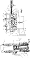
- Such mechanism comprises a support structure, supporting a control device of the position of setting device 2, formed by a movable equipment 31, by an actuator for vertical movement 34 and by an actuator for horizontal movement 35.
- Such actuators are adapted to be handled along horizontal "X"-axis of the support structure and of movable equipment 31, associated with setting device 2, along vertical "Z"-axis of the same movable equipment 31 for positioning setting device 2 with respect to the cartridge, which is kept in a predetermined position by a mechanism 6 for retaining cartridges.
- the setting mechanism also comprises a mechanism for recovering errors, adapted to correctly position setting device 2 on "XY"-plane in the case of a non-alignment of the cartridge from its ideal axis.
- the setting mechanism preferably takes three distinct positions, adapted to set the fuse without hindering the movement of the cartridge in the path comprised among the various steps of the loading and shooting system of the cartridges.
- the setting mechanism of the fuse is preferably positioned in the structure of firearm 5 covered by a gun carriage 53 of the firearm, positioned under a movable shield 51 and fixed to the structure of firearm 5 by means of at least one support flange 52.
- the cartridge coming from a lifting system adapted to bring the cartridges in the vicinity of the firearm is positioned for setting the fuse.
- Such cartridge is kept in such a position from retaining mechanism 6 of the cartridges, comprising a loading arm 61, adapted to position the cartridge itself, and a plurality of lifters 62, adapted to stop the cartridge in the correct position during its lifting.
- the support structure of the setting mechanism comprises a motor plate 11 to which at least two engines 33, preferably by screws, are fixed, adapted to rotate setting device 2, with a limit plate 12, facing and superimposed to motor plate 11, between which it moves vertically with respect to movable equipment 31.
- Motor plate 11 and limit plate 12 are spaced and kept in such position by a plurality of columns 14.
- Said columns 14 are preferably metal cylindrical bars, threaded at the end and fixed to motor plate 11 and to limit plate 12 preferably by means of bolts.
- the support structure also comprises support structure 13, preferably metallic and with an elongated shape, positioned between the two aforementioned plates and fixed to movable equipment 31, which can slide vertically.
- Such support structure 13 comprises at least two slots 131 and 131', preferably positioned at the two ends of structure 13, in which setting device 2 and a part of the control device are respectively positioned.
- Setting device 2 is positioned at the inside of slot 131 of support structure 13, and it comprises reference portion 21, integral with support structure 13, and setting portion 22, stacked and aligned with reference portion 21, adapted to make the setting of the fuse.
- Reference portion 21 and setting portion 22 are essentially ferrule-shaped and are inserted inside slot 131, so to rotate independently one from the other, due to a plurality of bearings.
- the rotation of reference portion 21 and of setting portion 22 is made by at least two preferably toothed belts 331, each of them directly connected with its respective portion, which transfer the motion from the electrical assigned motors 33.
- Such support structure 13 also performs a covering function for such belts 331, which slide inside a channel or carter, from slot 131 to slot 131', set in such structure 13.
- support structure 13 permits to withstand the mechanical stresses, due both to the handling of the setting mechanism during the various aforementioned steps and the various loads supported by such structure 13.
- Said loads can be both intrinsic to the operation and structure, and exceptional due to the malfunctioning of the chain mechanism inside the firearm, such as for example the breaking of one of lifters 62.
- a cover 25 is present, adapted to block and protect the portions inside slot 131, fixed to structure 13, preferably by screws.
- a base 24 adapted to support setting device 2 and all its parts.
- Setting device 2 also comprises a safety cone 26, positioned in the vicinity of reference portion 21, fixed to support structure 13 preferably by screws, and able to permit the correct insertion and facilitate the exit of the fuse of setting device 2. Furthermore, such cone 26 determines the adjustment of the position of setting device 2 permitted by the mechanism for recovering errors.
- the rotation method of reference portion 21 and of setting portion 22 for the setting step is similar to the known aforementioned method.
- Motors 33 are preferably positioned in the vicinity of the control device, for example under such device, fixed to the lower face of motor plate 11, preferably by screws.
- the control device comprises said movable equipment 31, actuator 34 for vertical movement and actuator 35 for horizontal movement, adapted to perform the handling of the setting mechanism in its entirety.
- Movable equipment 31 comprises a support plate 310, preferably metallic, to which support structure 13 is fixed as aforementioned, with at least two pulleys 332, preferably toothed and connected with motors 33, adapted to rotate setting device 2 by means of belts 331, and at least two belt-tensioners 334, adapted to tension belts 331.
- Pulleys 332 and belt-tensioners 334 are positioned in the upper face of supporting plate 310, inside slot 131' of structure 13.
- Belt-tensioners 334 are fixed through a pin so to make said belt-tensioners 334 idle in rotation around the vertical axis of such pins.
- Slot 131' assures a protection of pulleys 332 and belt-tensioner 334, as the height of such components is lower than the thickness of said slot 131' of support structure 13.
- Said pulleys 332 are connected to motors 33 by means of corresponding shafts 333, which are grooved to assure the transmission, on which such pulleys can translate.
- Said shafts 333, passing through corresponding holes for shafts 111 comprised in motor plate 11 preferably have a length equal to the length of columns 14.
- each shaft 333 at least one rotation control device 71 for rotation is present, which is preferably provided with an encoder for example optical, adapted to determine, with a reduced uncertainty, the angular variations.
- Said rotation control devices 71 are preferably positioned on such shafts 333 on limit plate 12.
- the movements detected by the rotation control device 71 are movements which are transferred from motors 33 by means of belts 331, to setting device 2 for setting the fuses.
- the vertical movement of movable equipment 31 occurs due to the actuator of a vertical movement 34, comprising at least one oleo-dynamic device 341, formed by two pistons, opposed and integrated in a single structure, and a braking device, adapted to reduce the elongation of such pistons and avoid too heavy shocks between structure 13 and limit plate 12.
- a braking device adapted to reduce the elongation of such pistons and avoid too heavy shocks between structure 13 and limit plate 12.
- Such braking device permits to slow down the elongation speed of the pistons, once having passed a certain extension of the pistons themselves.
- Such actuator 34 lifts the setting device 2 along axis "Z", bringing it preferably in the disengaged position, so avoiding to interfere with the movements of the ammunition when passing to other operating steps of the firearm.
- Actuator 34 of the vertical movement is preferably placed in a slot 112, comprised in motor plate 11 and placed on a side of plate 11 itself, in order not to interfere with movable equipment 31, and with the devices comprised inside slot 131', for handling setting device 2.
- Said actuator 34 by means of hooking portions 342 preferably realized through forks, is fixed both to movable equipment 31, in particular to plate 310, and to motor plate 11, preferably through screws.
- the braking device consists in a suitable cavity, made inside the structure of the cylinder in which the two pistons are contained. The end of one of the pistons, before support structure 13 meets its mechanical stop, enters in such cavity by forcing the exit of the oil through the aperture formed between the two engaged elements.
- Such cavity in the cylinder introduces a damping element in the equation of the motion, so reducing the elongation speed of the piston beyond a certain elongation of the same.
- Limit plate 12 advantageously comprises at least one detecting device, fixed to the lower face of such plate 12, adapted to determine the position of support structure 13 and also of equipment 31, during its vertical movement, by signaling the approach of the limit condition in the setting mechanism.
- the actuator 35 of horizontal movement is adapted to move along axis "X" the setting mechanism, by sliding it along at least one longitudinal guide 42, preferably fixed to the structure of firearm 5, positioned for example on support flange 52.
- the setting mechanism is retracted from the actuator 35of horizontal movement, in order to avoid to hinder the mechanical movements comprised in the firearm.
- Said actuator 35 comprises an hydraulic organ 351, fixed at an end to a fork, preferably through a pin, which is fixed to the structure of firearm 5.
- the actuator of horizontal movement 35 is preferably actuated for disengaging setting device 2, by bringing the setting mechanism in a disengaged position, preferably a retracted one, in order to make it inoperative.
- the setting mechanism is brought in such position for example during the eventual missing of a shot of the cartridge with the possible new storing step of an ammunition, for example in a magazine, in order not to interfere with such steps.
- Said actuator 35 at the other end is fixed to a "U-shaped flange 352" associated to motor plate 11 of the support structure.
- Such hydraulic organ 351 is preferably provided with a piston, the extension of which permits to the entire structure of the setting mechanism to perform a horizontal movement along axis "X".
- Flange 352 comprises vertical slots 353 in which the pins fixed to organ 351 slide.
- Flange 352 slides, due to sleds on which it is fixed, with respect to motor plate 11, on at least one track of said plate, longitudinally along elongation "X"-axis of hydraulic organ 351 (not shown in Figure).
- the mechanism for recovering errors permits to reduce the clearances along "X"-axis through at least one preferably helical recovery spring 41, centered both on flange 352 and on motor plate 11.
- two springs 41 are present, fixed to motor plate 11, and to the two arms of flange 352.
- the union between the actuator of vertical movement 34 and the actuator of horizontal movement 35 permits to reduce the dimensions of the mechanism, permitting to place such setting mechanism in narrow positions, such as under movable shield 51, but maintaining therefore the flexibility and the reliability of the mechanism.
- the mechanism for recovering errors comprises a plurality of sledges 44 which slide on a plurality of guides adapted to permit the movement in "XY"-plane, in particular longitudinal guide 42, adapted to permit the movements along longitudinal "X"-axis of the setting mechanism, at least one transversal guide 43, adapted to permit the transversal movements along "Y"-axis.
- Said recovery mechanism permits to the setting mechanism to position always in axis with the cartridge, by recovering the misalignment errors of various centimeters, which are useful in the case in which the firearm is subjected to movements and stresses, which can cause a wrong positioning of the cartridge for its setting step.
- the setting mechanism also performs another safety mechanical function, in case of failures of the retaining mechanism of cartridges6, such as for example the breaking of a lifter 62, as seen in Figure 9 .
- the setting mechanism In the even remote case in which retaining mechanism 6 does not work, the setting mechanism must act as a damping device of the motion of ammunition.
- support structure 13 and setting device 2 can absorb without damage the energy connected with the arrival of the ammunition.
- the present function of mechanical safety is preferably used also during the use of other types of cartridges, which do not need a mechanical setting step of the fuse.
- the setting mechanism is kept in a waiting position, by acting through the actuator of vertical movement 34.
- the present invention assures the operation of the setting mechanism also in critical conditions, or when applied to a ship with difficult sea conditions (for example sea force 6), by reducing the errors, according to MIL-STD-810C and MIL-STD-167B rules.
- actuation and piloting of motors 33 are managed by a central control unit (not shown), which also drives the actuators able to handle the setting mechanism.
- a further alternative embodiment provides for the removal of columns 14 and of limit plate 12, by making in a different way the detecting device, for example by fixing it directly on the structure of firearm 5.
- a further embodiment provides that motors 33 move integral with the motor plate, so permitting the removal of shafts 333.
- REFERENCE NUMBERS Motor plate 11 Holes for shafts 111 Slot for actuator 112 Limit plate 12 Support structure 13 Slots 131 Columns 14 Setting device 2 Reference portion 21 Setting portion 22 Bearings 23 Base 24 Cover 25 Safety cone 26 Movable equipment 31 Support plate 310 Motors 33 Belts 331 Pulleys 332 Transmission shafts 333 Belt-tensioners 334 Actuator for vertical movement 34 Oleo-dynamic device 341 Hooking portions 342 Actuator for horizontal movement 35 Hydraulic organ 351 Flange 352 Vertical slots 353 Recovery spring 41 Longitudinal guide 42 Transversal guide 43 Sled 44 Firearm structure 5 Movable shield 51 Support flange 52 Carriage 53 Mechanism for retaining cartridges 6 Loading arm 61 Lifters 62 Device for controlling rotation 71
Landscapes
- Engineering & Computer Science (AREA)
- General Engineering & Computer Science (AREA)
- Portable Nailing Machines And Staplers (AREA)
- Toys (AREA)
- Fuses (AREA)
- Particle Accelerators (AREA)
- Surgical Instruments (AREA)
- Physical Deposition Of Substances That Are Components Of Semiconductor Devices (AREA)
- Finger-Pressure Massage (AREA)
- Fishing Rods (AREA)
- Electronic Switches (AREA)
Priority Applications (3)
| Application Number | Priority Date | Filing Date | Title |
|---|---|---|---|
| PL11166830T PL2390618T3 (pl) | 2010-05-26 | 2011-05-20 | Mechanizm do nastawiania zapalników do amunicji |
| SI201131163A SI2390618T1 (sl) | 2010-05-26 | 2011-05-20 | Mehanizem za nastavitev vžigalnika |
| HRP20170576TT HRP20170576T1 (hr) | 2010-05-26 | 2017-04-11 | Mehanizam za postavljanje osigurača |
Applications Claiming Priority (1)
| Application Number | Priority Date | Filing Date | Title |
|---|---|---|---|
| ITTO2010A000439A IT1400535B1 (it) | 2010-05-26 | 2010-05-26 | Meccanismo di graduazione per spoletta |
Publications (2)
| Publication Number | Publication Date |
|---|---|
| EP2390618A1 EP2390618A1 (en) | 2011-11-30 |
| EP2390618B1 true EP2390618B1 (en) | 2017-03-15 |
Family
ID=43432364
Family Applications (1)
| Application Number | Title | Priority Date | Filing Date |
|---|---|---|---|
| EP11166830.7A Active EP2390618B1 (en) | 2010-05-26 | 2011-05-20 | Mechanism for setting a fuse |
Country Status (14)
| Country | Link |
|---|---|
| US (1) | US8839705B2 (pl) |
| EP (1) | EP2390618B1 (pl) |
| JP (1) | JP6027725B2 (pl) |
| CA (1) | CA2741371C (pl) |
| CY (1) | CY1119187T1 (pl) |
| DK (1) | DK2390618T3 (pl) |
| ES (1) | ES2623874T3 (pl) |
| HR (1) | HRP20170576T1 (pl) |
| IT (1) | IT1400535B1 (pl) |
| LT (1) | LT2390618T (pl) |
| PL (1) | PL2390618T3 (pl) |
| PT (1) | PT2390618T (pl) |
| SG (1) | SG176398A1 (pl) |
| SI (1) | SI2390618T1 (pl) |
Families Citing this family (2)
| Publication number | Priority date | Publication date | Assignee | Title |
|---|---|---|---|---|
| DE102020108567A1 (de) * | 2020-03-27 | 2021-09-30 | Krauss-Maffei Wegmann Gmbh & Co. Kg | Programmiervorrichtung |
| CN112902773A (zh) * | 2020-12-28 | 2021-06-04 | 北方导航控制技术股份有限公司 | 一种夹抱引信旋紧专机 |
Family Cites Families (10)
| Publication number | Priority date | Publication date | Assignee | Title |
|---|---|---|---|---|
| NL50817C (pl) * | 1938-06-16 | |||
| US2451764A (en) * | 1941-06-18 | 1948-10-19 | Molins Machine Co Ltd | Fuse setting apparatus |
| US2887011A (en) * | 1943-12-20 | 1959-05-19 | Molins Machine Co Ltd | Fuse setter combined with loading mechanism |
| GB808480A (en) * | 1945-01-31 | 1959-02-04 | Valentine Pearce Harvey | Improvements in or relating to fuze-setting apparatus |
| US2442842A (en) * | 1946-07-15 | 1948-06-08 | United Shoe Machinery Corp | Fuse setter |
| DE1578509A1 (de) * | 1966-06-11 | 1970-07-16 | Telefunken Patent | Zuenderstellmaschine |
| CH502572A (de) * | 1968-12-19 | 1971-01-31 | Oerlikon Buehrle Ag | Raketenwerfer |
| CH503254A (de) * | 1969-02-13 | 1971-02-15 | Oerlikon Buehrle Ag | Stellorgan zum Einstellen eines Zünders an einem Geschoss |
| JPS4929880B1 (pl) * | 1969-12-15 | 1974-08-08 | ||
| DE19901673A1 (de) * | 1999-01-18 | 2000-07-20 | Krauss Maffei Wegmann Gmbh & C | Vorrichtung zur berührungslosen Zündereinstellung für großkalibrige Geschosse |
-
2010
- 2010-05-26 IT ITTO2010A000439A patent/IT1400535B1/it active
-
2011
- 2011-05-20 PT PT111668307T patent/PT2390618T/pt unknown
- 2011-05-20 DK DK11166830.7T patent/DK2390618T3/en active
- 2011-05-20 ES ES11166830.7T patent/ES2623874T3/es active Active
- 2011-05-20 EP EP11166830.7A patent/EP2390618B1/en active Active
- 2011-05-20 LT LTEP11166830.7T patent/LT2390618T/lt unknown
- 2011-05-20 PL PL11166830T patent/PL2390618T3/pl unknown
- 2011-05-20 SI SI201131163A patent/SI2390618T1/sl unknown
- 2011-05-24 CA CA2741371A patent/CA2741371C/en active Active
- 2011-05-25 JP JP2011116540A patent/JP6027725B2/ja active Active
- 2011-05-25 SG SG2011037827A patent/SG176398A1/en unknown
- 2011-05-25 US US13/115,739 patent/US8839705B2/en active Active
-
2017
- 2017-04-11 HR HRP20170576TT patent/HRP20170576T1/hr unknown
- 2017-04-19 CY CY20171100447T patent/CY1119187T1/el unknown
Non-Patent Citations (1)
| Title |
|---|
| None * |
Also Published As
| Publication number | Publication date |
|---|---|
| US20110290100A1 (en) | 2011-12-01 |
| SI2390618T1 (sl) | 2017-07-31 |
| ITTO20100439A1 (it) | 2011-11-27 |
| DK2390618T3 (en) | 2017-05-01 |
| SG176398A1 (en) | 2011-12-29 |
| CA2741371C (en) | 2019-07-09 |
| ES2623874T3 (es) | 2017-07-12 |
| EP2390618A1 (en) | 2011-11-30 |
| HRP20170576T1 (hr) | 2017-06-16 |
| IT1400535B1 (it) | 2013-06-11 |
| JP6027725B2 (ja) | 2016-11-16 |
| US8839705B2 (en) | 2014-09-23 |
| JP2011247578A (ja) | 2011-12-08 |
| LT2390618T (lt) | 2017-06-26 |
| CY1119187T1 (el) | 2018-02-14 |
| PT2390618T (pt) | 2017-05-03 |
| CA2741371A1 (en) | 2011-11-26 |
| PL2390618T3 (pl) | 2017-08-31 |
Similar Documents
| Publication | Publication Date | Title |
|---|---|---|
| US8413565B2 (en) | Drive and quick stop for a weapon with preferably a linear breech or ammunition feed | |
| CN104613828B (zh) | 一种用于旋转弹药的mems离心保险机构及其保险方法 | |
| US8839705B2 (en) | Mechanism for setting a fuse | |
| KR101700291B1 (ko) | 이중 안전장전장치 | |
| EP3514474B1 (en) | Safety device for firearms and safety method for firearms | |
| US20200096270A1 (en) | Delinker mechanism for chain-driven machine gun | |
| US10066892B1 (en) | Modular automated mortar weapon for mobile applications | |
| KR101621146B1 (ko) | 무장 장착대 | |
| US10132393B2 (en) | Mechanical stepper motors for guided munitions and industrial machinery | |
| KR20110133446A (ko) | 양탄기 | |
| US20250207882A1 (en) | Multiple-barrel firearm and method of use | |
| KR101194322B1 (ko) | 인공위성용 분리장치 | |
| EP2282157B1 (de) | Fernsteuerbare Spannvorrichtung für Maschinengewehre mit Durchladeschieber | |
| KR102906168B1 (ko) | 기계적 안전 시스템들을 구동하기 위한 장치 | |
| EP1848949B1 (en) | Device for transferring projectile into barrel of weapon | |
| US20120167750A1 (en) | Rapid fire launch system | |
| KR101657363B1 (ko) | 무장 장착대 | |
| US20200326146A1 (en) | Device for loading a barreled weapon with ammunition bodies | |
| EP1216392B1 (en) | Ammunition handling system | |
| US10464356B2 (en) | Transmission link assemblies | |
| RU2311608C2 (ru) | Артиллерийское орудие | |
| TR2025007734A2 (tr) | Torpi̇do transfer si̇stemi̇ | |
| US4421008A (en) | Timed round stop for a sprocket fed weapon | |
| NO349338B1 (en) | Interchange system for a weapon mount | |
| CN119982250A (zh) | 一种用于燃烧室自动插芯的夹取机构 |
Legal Events
| Date | Code | Title | Description |
|---|---|---|---|
| AK | Designated contracting states |
Kind code of ref document: A1 Designated state(s): AL AT BE BG CH CY CZ DE DK EE ES FI FR GB GR HR HU IE IS IT LI LT LU LV MC MK MT NL NO PL PT RO RS SE SI SK SM TR |
|
| AX | Request for extension of the european patent |
Extension state: BA ME |
|
| PUAI | Public reference made under article 153(3) epc to a published international application that has entered the european phase |
Free format text: ORIGINAL CODE: 0009012 |
|
| 17P | Request for examination filed |
Effective date: 20120529 |
|
| GRAP | Despatch of communication of intention to grant a patent |
Free format text: ORIGINAL CODE: EPIDOSNIGR1 |
|
| INTG | Intention to grant announced |
Effective date: 20160630 |
|
| RAP1 | Party data changed (applicant data changed or rights of an application transferred) |
Owner name: LEONARDO S.P.A. |
|
| GRAS | Grant fee paid |
Free format text: ORIGINAL CODE: EPIDOSNIGR3 |
|
| GRAA | (expected) grant |
Free format text: ORIGINAL CODE: 0009210 |
|
| AK | Designated contracting states |
Kind code of ref document: B1 Designated state(s): AL AT BE BG CH CY CZ DE DK EE ES FI FR GB GR HR HU IE IS IT LI LT LU LV MC MK MT NL NO PL PT RO RS SE SI SK SM TR |
|
| REG | Reference to a national code |
Ref country code: CH Ref legal event code: EP Ref country code: GB Ref legal event code: FG4D |
|
| REG | Reference to a national code |
Ref country code: IE Ref legal event code: FG4D |
|
| REG | Reference to a national code |
Ref country code: HR Ref legal event code: TUEP Ref document number: P20170576 Country of ref document: HR |
|
| REG | Reference to a national code |
Ref country code: RO Ref legal event code: EPE |
|
| REG | Reference to a national code |
Ref country code: AT Ref legal event code: REF Ref document number: 876019 Country of ref document: AT Kind code of ref document: T Effective date: 20170415 |
|
| REG | Reference to a national code |
Ref country code: NL Ref legal event code: FP |
|
| REG | Reference to a national code |
Ref country code: DE Ref legal event code: R096 Ref document number: 602011035881 Country of ref document: DE |
|
| REG | Reference to a national code |
Ref country code: DK Ref legal event code: T3 Effective date: 20170427 |
|
| REG | Reference to a national code |
Ref country code: PT Ref legal event code: SC4A Ref document number: 2390618 Country of ref document: PT Date of ref document: 20170503 Kind code of ref document: T Free format text: AVAILABILITY OF NATIONAL TRANSLATION Effective date: 20170419 |
|
| REG | Reference to a national code |
Ref country code: SE Ref legal event code: TRGR |
|
| REG | Reference to a national code |
Ref country code: FR Ref legal event code: PLFP Year of fee payment: 7 |
|
| REG | Reference to a national code |
Ref country code: NO Ref legal event code: T2 Effective date: 20170315 |
|
| REG | Reference to a national code |
Ref country code: HR Ref legal event code: T1PR Ref document number: P20170576 Country of ref document: HR |
|
| REG | Reference to a national code |
Ref country code: ES Ref legal event code: FG2A Ref document number: 2623874 Country of ref document: ES Kind code of ref document: T3 Effective date: 20170712 |
|
| REG | Reference to a national code |
Ref country code: EE Ref legal event code: FG4A Ref document number: E013819 Country of ref document: EE Effective date: 20170417 |
|
| PG25 | Lapsed in a contracting state [announced via postgrant information from national office to epo] |
Ref country code: LU Free format text: LAPSE BECAUSE OF NON-PAYMENT OF DUE FEES Effective date: 20170531 Ref country code: RS Free format text: LAPSE BECAUSE OF FAILURE TO SUBMIT A TRANSLATION OF THE DESCRIPTION OR TO PAY THE FEE WITHIN THE PRESCRIBED TIME-LIMIT Effective date: 20170315 |
|
| REG | Reference to a national code |
Ref country code: SK Ref legal event code: T3 Ref document number: E 24049 Country of ref document: SK |
|
| PG25 | Lapsed in a contracting state [announced via postgrant information from national office to epo] |
Ref country code: IT Free format text: LAPSE BECAUSE OF FAILURE TO SUBMIT A TRANSLATION OF THE DESCRIPTION OR TO PAY THE FEE WITHIN THE PRESCRIBED TIME-LIMIT Effective date: 20170315 |
|
| REG | Reference to a national code |
Ref country code: GR Ref legal event code: EP Ref document number: 20170401253 Country of ref document: GR Effective date: 20171023 |
|
| PG25 | Lapsed in a contracting state [announced via postgrant information from national office to epo] |
Ref country code: IS Free format text: LAPSE BECAUSE OF FAILURE TO SUBMIT A TRANSLATION OF THE DESCRIPTION OR TO PAY THE FEE WITHIN THE PRESCRIBED TIME-LIMIT Effective date: 20170715 Ref country code: SM Free format text: LAPSE BECAUSE OF FAILURE TO SUBMIT A TRANSLATION OF THE DESCRIPTION OR TO PAY THE FEE WITHIN THE PRESCRIBED TIME-LIMIT Effective date: 20170315 |
|
| REG | Reference to a national code |
Ref country code: DE Ref legal event code: R097 Ref document number: 602011035881 Country of ref document: DE |
|
| REG | Reference to a national code |
Ref country code: CH Ref legal event code: PL |
|
| PLBE | No opposition filed within time limit |
Free format text: ORIGINAL CODE: 0009261 |
|
| STAA | Information on the status of an ep patent application or granted ep patent |
Free format text: STATUS: NO OPPOSITION FILED WITHIN TIME LIMIT |
|
| PG25 | Lapsed in a contracting state [announced via postgrant information from national office to epo] |
Ref country code: MC Free format text: LAPSE BECAUSE OF FAILURE TO SUBMIT A TRANSLATION OF THE DESCRIPTION OR TO PAY THE FEE WITHIN THE PRESCRIBED TIME-LIMIT Effective date: 20170315 |
|
| 26N | No opposition filed |
Effective date: 20171218 |
|
| REG | Reference to a national code |
Ref country code: IE Ref legal event code: MM4A |
|
| PG25 | Lapsed in a contracting state [announced via postgrant information from national office to epo] |
Ref country code: LI Free format text: LAPSE BECAUSE OF NON-PAYMENT OF DUE FEES Effective date: 20170531 Ref country code: CH Free format text: LAPSE BECAUSE OF NON-PAYMENT OF DUE FEES Effective date: 20170531 |
|
| PG25 | Lapsed in a contracting state [announced via postgrant information from national office to epo] |
Ref country code: LU Free format text: LAPSE BECAUSE OF NON-PAYMENT OF DUE FEES Effective date: 20170520 |
|
| REG | Reference to a national code |
Ref country code: FR Ref legal event code: PLFP Year of fee payment: 8 |
|
| REG | Reference to a national code |
Ref country code: BE Ref legal event code: MM Effective date: 20170531 |
|
| PG25 | Lapsed in a contracting state [announced via postgrant information from national office to epo] |
Ref country code: IE Free format text: LAPSE BECAUSE OF NON-PAYMENT OF DUE FEES Effective date: 20170520 |
|
| PG25 | Lapsed in a contracting state [announced via postgrant information from national office to epo] |
Ref country code: BE Free format text: LAPSE BECAUSE OF NON-PAYMENT OF DUE FEES Effective date: 20170531 |
|
| PG25 | Lapsed in a contracting state [announced via postgrant information from national office to epo] |
Ref country code: MT Free format text: LAPSE BECAUSE OF NON-PAYMENT OF DUE FEES Effective date: 20170520 |
|
| REG | Reference to a national code |
Ref country code: AT Ref legal event code: UEP Ref document number: 876019 Country of ref document: AT Kind code of ref document: T Effective date: 20170315 |
|
| REG | Reference to a national code |
Ref country code: HR Ref legal event code: ODRP Ref document number: P20170576 Country of ref document: HR Payment date: 20190329 Year of fee payment: 9 |
|
| PG25 | Lapsed in a contracting state [announced via postgrant information from national office to epo] |
Ref country code: HU Free format text: LAPSE BECAUSE OF FAILURE TO SUBMIT A TRANSLATION OF THE DESCRIPTION OR TO PAY THE FEE WITHIN THE PRESCRIBED TIME-LIMIT; INVALID AB INITIO Effective date: 20110520 |
|
| PG25 | Lapsed in a contracting state [announced via postgrant information from national office to epo] |
Ref country code: MK Free format text: LAPSE BECAUSE OF FAILURE TO SUBMIT A TRANSLATION OF THE DESCRIPTION OR TO PAY THE FEE WITHIN THE PRESCRIBED TIME-LIMIT Effective date: 20170315 |
|
| REG | Reference to a national code |
Ref country code: HR Ref legal event code: ODRP Ref document number: P20170576 Country of ref document: HR Payment date: 20200512 Year of fee payment: 10 |
|
| PG25 | Lapsed in a contracting state [announced via postgrant information from national office to epo] |
Ref country code: AL Free format text: LAPSE BECAUSE OF FAILURE TO SUBMIT A TRANSLATION OF THE DESCRIPTION OR TO PAY THE FEE WITHIN THE PRESCRIBED TIME-LIMIT Effective date: 20170315 |
|
| REG | Reference to a national code |
Ref country code: HR Ref legal event code: ODRP Ref document number: P20170576 Country of ref document: HR Payment date: 20210512 Year of fee payment: 11 |
|
| REG | Reference to a national code |
Ref country code: EE Ref legal event code: HC1A Ref document number: E013819 Country of ref document: EE |
|
| REG | Reference to a national code |
Ref country code: HR Ref legal event code: ODRP Ref document number: P20170576 Country of ref document: HR Payment date: 20220510 Year of fee payment: 12 |
|
| REG | Reference to a national code |
Ref country code: HR Ref legal event code: ODRP Ref document number: P20170576 Country of ref document: HR Payment date: 20230510 Year of fee payment: 13 |
|
| REG | Reference to a national code |
Ref country code: HR Ref legal event code: ODRP Ref document number: P20170576 Country of ref document: HR Payment date: 20240509 Year of fee payment: 14 |
|
| REG | Reference to a national code |
Ref country code: HR Ref legal event code: ODRP Ref document number: P20170576 Country of ref document: HR Payment date: 20250512 Year of fee payment: 15 |
|
| PGFP | Annual fee paid to national office [announced via postgrant information from national office to epo] |
Ref country code: NL Payment date: 20250522 Year of fee payment: 15 |
|
| PGFP | Annual fee paid to national office [announced via postgrant information from national office to epo] |
Ref country code: FI Payment date: 20250520 Year of fee payment: 15 |
|
| PGFP | Annual fee paid to national office [announced via postgrant information from national office to epo] |
Ref country code: PL Payment date: 20250508 Year of fee payment: 15 Ref country code: DE Payment date: 20250519 Year of fee payment: 15 |
|
| PGFP | Annual fee paid to national office [announced via postgrant information from national office to epo] |
Ref country code: GB Payment date: 20250527 Year of fee payment: 15 Ref country code: ES Payment date: 20250616 Year of fee payment: 15 Ref country code: DK Payment date: 20250521 Year of fee payment: 15 |
|
| PGFP | Annual fee paid to national office [announced via postgrant information from national office to epo] |
Ref country code: LT Payment date: 20250507 Year of fee payment: 15 |
|
| PGFP | Annual fee paid to national office [announced via postgrant information from national office to epo] |
Ref country code: NO Payment date: 20250520 Year of fee payment: 15 |
|
| PGFP | Annual fee paid to national office [announced via postgrant information from national office to epo] |
Ref country code: HR Payment date: 20250512 Year of fee payment: 15 |
|
| PGFP | Annual fee paid to national office [announced via postgrant information from national office to epo] |
Ref country code: PT Payment date: 20250507 Year of fee payment: 15 Ref country code: LV Payment date: 20250522 Year of fee payment: 15 |
|
| PGFP | Annual fee paid to national office [announced via postgrant information from national office to epo] |
Ref country code: FR Payment date: 20250526 Year of fee payment: 15 Ref country code: EE Payment date: 20250526 Year of fee payment: 15 |
|
| PGFP | Annual fee paid to national office [announced via postgrant information from national office to epo] |
Ref country code: BG Payment date: 20250516 Year of fee payment: 15 Ref country code: GR Payment date: 20250519 Year of fee payment: 15 |
|
| PGFP | Annual fee paid to national office [announced via postgrant information from national office to epo] |
Ref country code: RO Payment date: 20250519 Year of fee payment: 15 Ref country code: AT Payment date: 20250519 Year of fee payment: 15 |
|
| PGFP | Annual fee paid to national office [announced via postgrant information from national office to epo] |
Ref country code: SK Payment date: 20250513 Year of fee payment: 15 Ref country code: TR Payment date: 20250514 Year of fee payment: 15 |
|
| PGFP | Annual fee paid to national office [announced via postgrant information from national office to epo] |
Ref country code: CZ Payment date: 20250507 Year of fee payment: 15 |
|
| PGFP | Annual fee paid to national office [announced via postgrant information from national office to epo] |
Ref country code: SI Payment date: 20250512 Year of fee payment: 15 Ref country code: SE Payment date: 20250522 Year of fee payment: 15 |
|
| PGFP | Annual fee paid to national office [announced via postgrant information from national office to epo] |
Ref country code: CY Payment date: 20250509 Year of fee payment: 15 |