EP2390577A1 - User interface and appliance of household or industrial type, especially domestic appliance - Google Patents
User interface and appliance of household or industrial type, especially domestic appliance Download PDFInfo
- Publication number
- EP2390577A1 EP2390577A1 EP10005608A EP10005608A EP2390577A1 EP 2390577 A1 EP2390577 A1 EP 2390577A1 EP 10005608 A EP10005608 A EP 10005608A EP 10005608 A EP10005608 A EP 10005608A EP 2390577 A1 EP2390577 A1 EP 2390577A1
- Authority
- EP
- European Patent Office
- Prior art keywords
- user interface
- mounting frame
- electronic board
- touch
- fixture
- Prior art date
- Legal status (The legal status is an assumption and is not a legal conclusion. Google has not performed a legal analysis and makes no representation as to the accuracy of the status listed.)
- Granted
Links
Images


Classifications
-
- F—MECHANICAL ENGINEERING; LIGHTING; HEATING; WEAPONS; BLASTING
- F24—HEATING; RANGES; VENTILATING
- F24C—DOMESTIC STOVES OR RANGES ; DETAILS OF DOMESTIC STOVES OR RANGES, OF GENERAL APPLICATION
- F24C7/00—Stoves or ranges heated by electric energy
- F24C7/08—Arrangement or mounting of control or safety devices
- F24C7/082—Arrangement or mounting of control or safety devices on ranges, e.g. control panels, illumination
-
- A—HUMAN NECESSITIES
- A47—FURNITURE; DOMESTIC ARTICLES OR APPLIANCES; COFFEE MILLS; SPICE MILLS; SUCTION CLEANERS IN GENERAL
- A47J—KITCHEN EQUIPMENT; COFFEE MILLS; SPICE MILLS; APPARATUS FOR MAKING BEVERAGES
- A47J37/00—Baking; Roasting; Grilling; Frying
- A47J37/12—Deep fat fryers, e.g. for frying fish or chips
- A47J37/1266—Control devices, e.g. to control temperature, level or quality of the frying liquid
-
- H—ELECTRICITY
- H05—ELECTRIC TECHNIQUES NOT OTHERWISE PROVIDED FOR
- H05K—PRINTED CIRCUITS; CASINGS OR CONSTRUCTIONAL DETAILS OF ELECTRIC APPARATUS; MANUFACTURE OF ASSEMBLAGES OF ELECTRICAL COMPONENTS
- H05K5/00—Casings, cabinets or drawers for electric apparatus
- H05K5/0017—Casings, cabinets or drawers for electric apparatus with operator interface units
- H05K5/0018—Casings, cabinets or drawers for electric apparatus with operator interface units having an electronic display
Landscapes
- Engineering & Computer Science (AREA)
- Food Science & Technology (AREA)
- Chemical & Material Sciences (AREA)
- Combustion & Propulsion (AREA)
- Mechanical Engineering (AREA)
- General Engineering & Computer Science (AREA)
- Microelectronics & Electronic Packaging (AREA)
- Switch Cases, Indication, And Locking (AREA)
- Push-Button Switches (AREA)
- Selective Calling Equipment (AREA)
- Details Of Connecting Devices For Male And Female Coupling (AREA)
Abstract
Description
- The present application is directed to a user interface and an appliance of household or industrial type, especially a domestic appliance.
- A user interface for a cooking hob is known from
DE 100 15 973 A1 , for example. The user interface comprises an electronic board that is snap-connected to a mounting frame which is glued to a lower side of the cooking hob. The electronic board is mounted to the mounting frame via a push-and-rotate movement in that it is first inserted into an anchor section engaging an outer rim section thereof, and then it is rotated such that snap hooks engage an opposite rim section. -
DE 199 50 829 A1 discloses a user interface for a baking oven. The user interface comprises a fixture to which an electronic interface unit is secured by means of a clamping frame which frame is snap-connected to the fixture. - It is an object of the invention to provide an alternative user interface for an appliance of household or industrial type. In particular, a user interface shall be provided which can be easily assembled and disassembled and which allows to reliably and precisely position and fix components thereof. Further, an appliance of household or industrial type shall be provided.
- This object is achieved by
independent claims 1 and 12. Embodiments of the invention result from dependent claims. - According to
independent claim 1, a user interface for an appliance of household or industrial type, especially for a domestic appliance, is provided. The user interface comprises at least one control unit, preferably a touch-field unit. The touch-field unit may be of infrared or capacitive type and adapted to allow a user to select or adjust certain parameters for operating the appliance in touching a respective touch panel presented to the user. The touch-field unit may comprise one or more individual touch-field elements or sensors. The control unit may comprise further active and passive actuators or control elements such as push and/or rotating type buttons, sliders and the like. A control unit in the sense of the present invention in particular shall allow a user to at least partially control the operation of a respective appliance, i. e. it shall allow active user intervention. - The user interface further comprises at least one electronic board. The electronic board may comprise electronic components for operating and controlling the control unit, in particular touch-field unit, and, if adequate, the appliance or at least some functions thereof.
- The at least one control unit, in particular touch-field unit, and electronic board, - at least a respective pair of such elements - are detachably mounted to a mounting frame of the user interface. Further they are arranged and designed such that electronic contact between mutual contact elements thereof is automatically established upon mounting the respective control unit, in particular touch-field unit, and electronic board to the mounting frame. Obviously, automatically establishing electrical contact greatly simplifies the mounting process. In addition, faulty electric contacting can largely be prevented.
- In an embodiment, the user interface may further comprise a fixture, which may be a front fixture to be positioned at or attached to a front panel of the appliance. A transparent cover, preferably made of glass, a glass analogue material or plastic, is positioned on the fixture and fixed, if required. Further, the mounting frame is attached to the fixture, in a more preferred embodiment attached to the transparent cover. The transparent cover may be part of a front or top face or cover plate presented and accessible to the user of the appliance. Transparency of the transparent cover in particular shall include all kinds of transparency and translucence.
- The mounting frame is favourably attached to the fixture or transparent cover via glue or other suitable attachment means allowing safe and tight attachment. Here again, the mounting process is comparatively simple, straight forward and time saving.
- In a further embodiment of the user interface, at least one pair of control unit and electronic board is arranged with at least partial overlap in successive planes. The contact elements are arranged in a region of overlap on respective sides of the control unit and electronic board facing each other. This configuration allows the respective control unit and electronic board to be successively attached to the mounting frame whilst guaranteeing automatic electric contacting.
- Attachment of the control unit and electronic board to the mounting frame and electric contacting can be achieved with respective single attachment movements or steps, not requiring separate and additional steps for establishing electrical contacts. Note that the term in successive planes shall in particular mean that the respective planes are parallel and arranged one behind the other relative to the fixture or transparent cover.
- In yet a further embodiment, the electronic board is detachably mounted to a positioning frame. The positioning frame in turn is detachably mounted to the mounting frame or fixture. Guiding elements or rails and respective engagement elements can be provided, specially adapted to secure safe, easy and proper alignment of the positioning frame relative to the control unit, mounting frame and fixture, respectively. Note that guiding elements or rails and respective engagement elements also can be provided in connection with the control unit or other components of the user interface in order to secure proper and easy alignment thereof.
- As indicated beforehand, the user interface may comprise further components, in particular electronic components. Hence, in yet another embodiment, the user interface comprises at least one actuator detachably mounted to at least one of the mounting frame and positioning frame. The actuator may be a switch, control knob, in particular a rotary and/or push type knob or button. Preferably, at least one of an electric or mechanic contact to actuating elements, such as switches or push buttons and the like, is automatically established upon mounting the actuator to the mounting frame. Such a configuration simplifies attachment of additional actuators and the like and contributes to rapid and safe assembly of the user interface.
- A further embodiment may comprise at least one reflector unit arranged downstream the control unit. Downstream in particular shall apply to a side of the control unit, in particular touch-field unit averted from the fixture or transparent cover. In the regular mounting position of the user interface the side averted from the fixture or transparent cover can be named rear or back side, whereas the side of the transparent cover can be named front side which generally is presented to and faces towards a user of the appliance.
- The reflector unit is preferably designed and adapted such that it presses or urges the control unit, in particular touch-field unit, against or towards the fixture or transparent cover. Further, it is preferred that the positioning frame is adapted and designed such that it presses at least one of the control unit, in particular touch-field unit, against the fixture or transparent cover and the reflector unit against the control unit, in particular touch-field unit. Such a configuration expediently urges the control unit against rear sides of the fixture or transparent cover, and the reflector against the control unit, in particular touch-field unit. In this way, at least the control unit, in particular touch-field unit, and the reflector can be tightly and firmly attached and fixed in respective desired positions, leading to enhanced operability and functionality.
- In an expedient embodiment, at least one of the mounting frame, positioning frame and fixture comprises at least one of snap elements and guides, in particular guide rails, designed and adapted to engage the at least one control unit, in particular touch-field unit, at least one electronic board, at least one actuator, at least one reflector and positioning frame, respectively. Such snap elements and guides preferably are adapted and designed for generating a pressing force towards the fixture or transparent cover, i. e. the components mentioned beforehand are pressed against or in a direction towards the fixture or transparent cover. Snap elements and guides provide easy and time saving assembly of the user interface. Also, the user interface can easily be disassembled for maintenance purposes for example, in particular in the case that one of the components has to be replaced.
- It is of further advantage that at least one of the mounting frame, positioning frame and fixture comprises at least one of lateral stops, transversal stops and height or depth stops, arranged and adapted for proper alignment of the at least one touch-field unit, electronic board, actuator, reflector, the positioning frame and mounting frame, in particular relative to each other.
- Using such stop elements, respective components of the user interface can be exactly oriented and positioned in at least two dimensions at respective levels, or even in three dimensions, relative to each other. This is of particular advantage because with the proposed user interface an electric contact between contact elements of the control unit and electronic board can be automatically established generally requiring proper prealignment of respective components in order to avoid damages to contact elements such as contact pins and the like.
- In this context it shall be noted that the contact elements, such as contact pins and mating receptacles, can be part of respective mating connectors.
- In a further embodiment, at least one spring element is provided which is designed for generating a pressing force directed towards the fixture or transparent section. Preferably the spring element acts upon at least one of the control unit, in particular touch-field unit, electronic board, actuator and reflector. Such additional spring elements can be provided if pressing forces of snap-elements and so on are likely to fail with fixing or attaching respective components reliably and sufficiently strong. In particular regions of high mass or weight load can be additionally secured and affixed by such spring elements.
- In a special configuration of the user interface that uses snap elements, at least one snap element which is already exerting a pressing force to a control field unit, electronic board, actuator and reflector is designed and configured such that upon deflection of the snap element in a direction opposite or transverse to the pressing force, away from the respective component for example, a slanted detent face thereof being raised thereby causing yet further overlap or further pitch with an engagement face of the respective component. Upon releasing the snap element a pressing force higher than the pressing force prevailing beforehand results. Such a snap element greatly simplifies assembly of the user interface.
- Such a favourable snap element can comprise a resilient clip and detent element resiliently attached or resiliently moulded to the clip. Here, the detent element can in principle move swing independently from the clip. It is in particular possible that the clip itself can be deflected relatively to a first pivot axis, and that the detent element can be deflected relatively to a second pivot axis running parallel and spaced from the first pivot axis.
- According to independent claim 12, an appliance of household or industrial type is provided, which comprises at least one user interface in any configuration described so far. As to advantages and advantageous effects of the appliance, reference is made to the discussion above.
- The user interface can be used with a great variety of appliances, such as ovens, in particular baking ovens, cooking ovens and microwave ovens, cooking hobs, refrigerators, freezers, washing machines and dishwashers, for example.
- Embodiments of the invention will now be described in connection with the annexed figures, in which
- Fig. 1
- shows a perspective back view of a user interface of a first embodiment;
- Fig. 2
- shows a mounting frame of the user interface of
Fig. 1 ; - Fig. 3
- shows a back view of the mounting frame with a touch-field unit being mounted thereto;
- Fig. 4
- shows the touch-field unit of
Fig. 3 ; - Fig. 5
- shows an electronic board to be mounted to the mounting frame;
- Fig. 6
- shows a cross sectional partial view of the user interface;
- Fig. 7
- shows a reflector;
- Fig. 8
- shows a cross sectional view of the user interface with the reflector being mounted to thereto;
- Fig. 9
- shows a back view of a user interface of a second embodiment;
- Fig. 10
- shows a touch-field unit of the user interface of
Fig. 9 ; - Fig. 11
- shows a back view of a mounting frame of the user interface of
Fig. 9 ; - Fig. 12
- shows a front view of a positioning frame;
- Fig. 13
- shows a cross sectional view a user interface in an actuator region;
- Fig. 14
- shows a detail of a snap connection;
- Fig. 15
- shows an enlarged view of a snap connector.
- The invention will now be described in connection with a user interface of a household cooking oven. However, this shall not be construed as limiting the scope of the invention. Rather, the invention can be applied and used in connection with any other type of household appliance, for example washing machines, dishwashers, microwave ovens, refrigerators, freezers and the like.
- If not otherwise stated like elements are denoted by like reference signs throughout the figures. The figures may not be true to scale, and scales of different figures may be different.
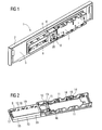
-
Fig. 1 shows in a perspective back view of a first embodiment of auser interface 1 of a cooking oven. - Note, that the term back view or back side shall mean that in the ordinary mounting position, the respective side is oriented towards the cooking oven or interior thereof and is therefore not visible from the outside. The term front view or front side shall mean that the respective side is oriented away from the appliance, if applicable visible from the outside.
- The
user interface 1 comprises afixture 2 that can be attached to the cooking oven (not shown). Aglass plate 3 is inlaid into thefixture 2, the front side of which constitutes a front face presented to a user of the cooking oven. - A mounting
frame 4 of theuser interface 1 is glued to the back side of thefixture 2, in more detail to theglass plate 3. A touch-field unit 5, areflector 6 and anelectronic board 7 are detachably mounted to the mountingframe 4. The mountingframe 4 further comprises a section to which anactuator 8, which may be a push and/or rotating type button, is detachably mounted to. -
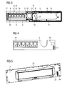
Fig. 2 shows the mountingframe 4 in more detail. The mountingframe 4 comprises first tothird snap connectors field unit 4, theelectronic board 7 andactuator 8, at least a circuit board thereof. - Further, first to
third guiding elements field unit 5, theelectronic board 7 andactuator 8 during the process of mounting them to the mountingframe 4. - In addition, first and second positioning pins 15 and 16 are provided with the mounting
frame 4. Furthermore, the mountingframe 4 comprises alateral stop 17, several transversal stops 18 and several depth stops 19. -
Fig. 3 shows a back view of the mountingframe 4 with the touch-field unit 5 being mounted thereto. As can be seen, the touch-field unit 5 comprisesseveral touch sensors 20, and further aconnector strip 21 with electric contact elements projecting from the back side of the touch-field unit 5. - The process of mounting the touch-
field unit 5 to the mountingframe 4 is now described with particular reference toFig. 3 . Note that the terms right hand side and left hand side, upper and lower used insofar correspond to respective representation shown in the Figures. - The touch-
field unit 5, which as such is shown inFig. 4 , is first pushed into the mountingframe 4 from the right hand side (Fig.3 ) towards the left hand side in a slightly tilted manner. The touch-field unit 5 is pushed into the mountingframe 4 underneath the section adapted to receive theactuator 8 whilst upper and lower edges of the touch-field unit 5 are guided by longitudinal guides respectively running from the right hand side to the left hand side. Here, guiding slots may be used. However, it is also possible that thefirst snap connectors 9, the first guiding elements and respective depth stops 19 additionally function as guiding elements. - The touch-
field unit 5 is pushed towards the left hand side until its left face side abuts thelateral stop 17. At this stage, the touch-field unit 5, in particular its right hand side, is pressed downwards such that at least thefirst snap connectors 9 positioned right-hand the actuator mounting section engage the touch-field unit 5 in respective upper and lower edge sections. In doing so, apositioning notch 22 engages thefirst positioning pin 15. - After performing these steps, the touch-
field unit 5 is detachably mounted to the mountingframe 4 with proper and fixed alignment in lateral, i. e. horizontal, and transverse, i. e. vertical, direction. Further, the level of the touch-field unit 5 is properly adjusted via the depth stops 19 or guiding elements, such as guide rails. In particular, horizontal and vertical movement as well as movement in depth direction can be prevented. -
Fig. 5 shows in a front view theelectronic board 7 to be mounted to the mountingframe 4. Theelectronic board 7 is mounted to the mountingframe 4 as follows: The electronic board is put onto the right hand side of the mounting frame 4 (Fig. 3 ), in more detail onto thethird snap connectors 11. Theelectronic board 7 is positioned in such a way that thethird guiding elements 14 engagerespective guiding notches 23, and that thesecond positioning pin 16 engages apositioning hole 24 of theelectronic board 7. Note that at least one guidingnotch 23 and a respective third guidingelement 14 may be adapted to properly center theelectronic board 7 in horizontal direction. Further, some of thethird guiding elements 14 may be adapted to properly center the electronic board in vertical direction. Now, theelectronic board 7 is pushed downwards, i. e. towards the mountingframe 4, such that it slides along thethird guiding elements 14 andsecond positioning pin 16 until thethird snap connectors 11 engage theelectronic board 7, in more detail respective edge sections thereof, and until theelectronic board 7 abuts respective depth stops 19. As can be seen, a proper alignment of theelectronic board 7 is automatically achieved upon snapping it into the mountingframe 4. - In the course of snapping the
electronic board 7 into the mountingframe 4, theconnector strip 21, i. e. respective contact elements, is/are automatically connected to a respectivefurther connector strip 25, i. e. respective further contact elements of theelectronic board 7. In this way, the touch-field unit 5 and theelectronic board 7 are electrically connected in an automated manner, which simplifies and speeds up the mounting procedure. Establishing the electric contact between the touch-field unit 5 and theelectronic board 7 is greatly facilitated by the fact that the touch-field unit 5 is properly aligned once mounted to the mountingframe 4, and that theelectronic board 7 can be mounted to the mounting frame in proper alignment relative to the touch-field unit 5. - After mounting the touch-
field unit 5 andelectronic board 7, theactuator 8, or at least acircuit board 26 thereof, can be snap connected to the mountingframe 4. Theactuator 8, in more detail thecircuit board 26, can be put from the back side into the respective opening such that the second guiding elements 12 engage respective guiding notches. At this stage, thecircuit board 26 can be pressed towards the mountingframe 4 such that thesecond snap connectors 10 engage thecircuit board 26. In this way, thecircuit board 26 is detachably mounted to the mountingframe 4 in proper alignment. After snap connecting thecircuit board 26 to the mountingframe 4, further components of theactuator 8, such as aknob 27 and the like, can be connected to thecircuit board 26 from the front or back side. -
Fig. 6 shows a cross sectional partial view of theuser interface 1. FromFig. 6 it becomes clear that the touch-field unit 5 is positioned immediately at theglass plate 3 and runs underneath the mounting section for theactuator 8 orcircuit board 26. Further it can be seen, that the touch-field unit 5 and theelectronic board 7 partially overlap in a region in which theconnector strip 21 andfurther connector strip 25 are positioned. Such a partial overlap may be advantageous in view of mechanical stability, but is not mandatory. Such a configuration in particular allows to automatically establishing electronic contact between the touch-field unit 5 andelectronic board 7. -
Fig. 7 shows thereflector 6 in more detail. Thereflector 6 comprisesseveral reflector zones 28 corresponding torespective touch sensors 20. Thereflector 6 further comprises outer spring hooks 29 and acentral spring hook 30. In addition, thereflector 6 comprises reflector snap hooks 31 and optionally upper and lower reflector stops 32. Thereflector 6 is mounted to the mountingframe 4 as follows, where further reference is made toFig. 8 showing a cross sectional view of theuser interface 1. - First, the outer spring hooks 29 and the
central spring hook 30 are inserted into respective slots 33 (Fig. 2 ). Then, the reflector snap connectors 34 are engaged with the reflector snap hooks 31, in a pushing action for example. Thereflector 6, in particular the outer spring hooks 29, thecentral spring hook 30 and the reflector snap hooks 31 are designed such that the reflector urges the touch-field unit 5 towards theglass plate 3. Thereby it can be assured that the touch-field unit 5 always is urged and butts against theglass plate 3, securing proper function of thetouch sensors 20. - In general, the
reflector 6 shall be properly aligned with respect to lateral, transversal and depth direction. If required, the upper and lower reflector stops 32 can be designed and adapted to fine tune depth alignment of thereflector 6. Further thecentral spring hook 30 and therespective slot 33 may be implemented with minimal play there between, thereby greatly restricting, or even preventing, lateral movability of thereflector 6. -
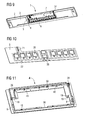
Fig. 9 shows a back view of auser interface 1 of a second embodiment. Note that the second embodiment is described only with respect to relevant constructional differences to the first embodiment. It shall be noted that all elements and components shown and described in connection with the first embodiment can be implemented with the second embodiment even if not expressly mentioned. - As becomes obvious from
Fig. 9 , the touch-field unit 5, theelectronic board 7 and thereflector 6, which is only optional, are successively arranged one after the other with a maximum of overlap. -
Fig. 10 shows a back view of the touch-field unit 5 of theuser interface 1 ofFig. 9 . The touch-field unit 5 comprisesseveral touch sensors 20, aconnector strip 21, apositioning notch 22 and apositioning edge 35. -
Fig. 11 shows a back view of arespective mounting frame 4 to which the touch-field unit 5 is mounted to. The mountingframe 4 comprises afirst positioning pin 15 and apositioning recess 36. - The touch-
field unit 5 is mounted to the mountingframe 4 as follows: First, thepositioning notch 22 is engaged with thefirst positioning pin 15. This secures the touch-field unit from lateral, i. e. horizontal, movement. In doing so, the lower edge of the touch-field unit 5 abuts a respective lower rim of the mountingframe 4 and thepositioning edge 35 engages thepositioning recess 36. - Then the touch-
field unit 5 is pressed towards the mountingframe 5 such that thefirst snap connectors 9 engage respective sites of the touch-field unit 5. Once snapped in, upper left and right edges of the touch-field unit abut respective transversal stops, securing the touch-field unit 5 from transversal, i. e. vertical, movement. As can be seen, the touch-field unit 5 can easily be mounted in a detachable manner to the mountingframe 4, with the touch-field unit 5 being fixedly and properly aligned and secured. - The
electronic board 7 of the second embodiment is configured like the one of the first embodiment. In contrast to the first embodiment, theelectronic board 7 in the present case is snap connected to aseparate positioning frame 37 which is shown in more detail inFig. 12 . Snap connecting theelectronic board 7 to thepositioning frame 37 is conducted similarly to snap connecting theelectronic board 7 of the first embodiment to the mountingframe 7. However, it is also or in addition possible that an upper or lower edge of theelectronic board 7 first is inserted into retaining straps protruding from thepositioning frame 37. Then theelectronic board 7 can be pushed towards thepositioning frame 37 thereby engaging respective snap connectors with respective snap sites of theelectronic board 7. Further, any type of guides, lateral, transversal and depth stops can be provided in order to properly and fixedly align theelectronic board 7 to thepositioning frame 37. - Once the
electronic board 7 is mounted to thepositioning frame 37, thepositioning frame 37 can be mounted to the mountingframe 4. This can be conducted as described below, where further reference is made toFig. 12 showing a front view of thepositioning frame 37, i. e. a side of thepositioning frame 37 finally facing the touch-field unit 5. - First, the
positioning frame 37 is placed on the mountingframe 4 such that third positioning pins 38 of thepositioning frame 37 engage fourth guidingelements 39 of the mountingframe 4. Note that the positioning pins 38 and fourth guidingelements 39 can be interchanged. - Then the positioning frame is pushed towards the mounting
frame 4, with the positioning pins 38 sliding along thefourth guiding elements 39, untilfourth snap connectors 40 of the mountingframe 4 engagerespective snap noses 41 of thepositioning frame 37. - Via the positioning pins 38 and fourth guiding
elements 39 thepositioning frame 37 is properly and fixedly aligned relative to the mountingframe 4, and is also secured against lateral, i. e. horizontal, or transversal, i. e. vertical, movement. Depth stops 19 provided with thepositioning frame 37 ensure that thepositioning frame 37 is positioned at a proper mounting level. - Upon mounting the
positioning frame 37 to the mountingframe 4, theconnector strip 21 of touch-field unit 5 is automatically connected to a respective further connector strip provided on the electronic board. As the positioning pins 38 and guidingelements 39 prevent thepositioning frame 37, and thereby the electronic board, from being tilted or moved in vertical or horizontal direction in the course of pushing them into the mountingframe 4, damages to theconnector strip 21 and further connector strip or contact pins thereof can greatly be avoided. -
Protrusions 42, in particular spring protrusions, protruding from a front side of the positioning frame, i. e. the side finally facing the touch-field unit 5, are designed and adapted to exert a pressing force upon the touch-field unit 5 in a direction towards theglass plate 3. The pressing force is such that the touch-field unit 5 is urged against theglass plate 3 in such a manner that optimal functionality and sensitivity of thetouch sensors 20 can be achieved. - If a
reflector 6 is to be mounted to the touch-field unit 5 of the second embodiment, the mountingframe 4 can comprise respective fastening elements, such as pin-hole-connector pairs, via which thereflector 6 can be attached to the mountingframe 4. In this case, theprotrusions 42 mentioned beforehand, or additional protrusions, may be used to exert a pressing force upon thereflector 6 in turn urging the touch-field unit 5 towards theglass plate 3 such that the touch-field unit 5 properly abuts theglass plate 3. If thereflector 6 is situated between theprotrusions 42 and the touch-field unit 5, theprotrusions 42 can be shortened accordingly. - If desired, the user interface according to the second embodiment may further comprise an
actuator 8 as already described in connection with the first embodiment. -
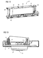
Fig. 13 shows a cross sectional view a user interface in an actuator region. Theactuator 8 comprises acircuit board 26 arranged at a back side, and aknob 27 arranged at a front side of theuser interface 1. Thecircuit board 26 is snap connected to the mountingframe 4 as already described further above. Theknob 27 can be inserted into a respective opening or hole of theglass panel 3 after thecircuit board 26, and preferably the touch-field unit 5 andelectronic board 7, is/are mounted to the mounting frame. -
Fig. 14 shows a detail of a snap connection with respect to asnap connector 9 provided for snap connecting the touch-field unit 5.Fig. 15 shows an enlarged view of thesnap connector 9. AlbeitFig. 14 shows a snap connection of the touch-field unit 5, the snap connection is not restricted to the touch-field-unit, but can be applied to all other snap connections mentioned so far, i. e. to first tofourth snap connectors 9 to 11 and 40. Therefore, the function of thesnap connector 9 will be described in general terms using the term "element" instead of touch-field unit 5. However, for sake of simplicity, thereference sign 9 is representatively used for the snap connector. - The
snap connector 9 comprises abase 43, from which a reversedU-shaped clip 44 extends upwardly. Theclip 44 is resiliently connected or moulded to thebase 43. Further, adetent element 45, in the present case comprising a detent hook 64 protruding in forward direction from thedetent element 45, extends downwardly from an upper bar of theclip 44. Thedetent element 45 is resiliently connected or moulded to the upper bar, i. e.clip 44. - If an element, such as the touch-
field unit 5, is snap connected, it is pushed downwards past theclip 44 and thedetent element 45 is first moved backwards, away from the element. If the element has passed thedetent element 45, the latter again moves in, i. e. forwards, thereby engaging the edge of the element. Thedetent element 45 prevents the element from moving up again. As adetent surface 47 is slanted and convex, thedetent element 45 exerts to the element a pressing force acting obliquely downwards in forward direction. - The special configuration of the
snap connector 9 allows to retrospectively increase the pressing force exerted on the element. As theclip 44 is resiliently connected to thebase 43, the upper side of theclip 44, the upper bar for example, can be pushed backwards, i. e. in a direction opposite to the forward direction. In doing so, thedetent surface 47 is elevated and thedetent element 45 can move further in forward direction such that the overlap between thedetent surface 47 and the element increases while the slanteddetent surface 47 continuously abuts the element. By pushing the detent element outwards, the bias or spring force of thedetent element 45 is increased and, as thedetent surface 47 abuts the element, an increased pressing force is exerted on the element upon releasing theclip 44 again. - The
detent element 45 can further comprise a step-like flap 48 protruding in downward direction of thedetent element 45 and acting as lateral or transversal stop. - As can be seen, the retention force of the
snap connector 9 can be increased retrospectively, leading to a safe and reliable snap connection. Further, the force needed to push the element past thesnap connector 9 can first be kept at a comparatively low level, while in retrospect it is still possible to achieve comparatively high pressing forces. - It shall be noted, that edges of the element can be chamfered such that the force needed to push the element past the snap connectors can be kept at a low level as compared to sharp edges.
- In all it becomes clear that the user interface as proposed herein can easily be assembled and disassembled again in a time saving manner but still allows to reliably and precisely position and fix respective elements.
-
- 1
- user interface
- 2
- fixture
- 3
- glass plate
- 4
- mounting frame
- 5
- touch-field unit
- 6
- reflector
- 7
- electronic board
- 8
- actuator
- 9 - 11
- first to third snap connectors
- 12 - 14
- first to third guiding elements
- 15 - 16
- first and second positioning pins
- 17
- lateral stop
- 18
- transversal stop
- 19
- depth stop
- 20
- touch sensor
- 21
- connector strip
- 22
- positioning notch
- 23
- guiding notch
- 24
- positioning hole
- 25
- further connector strip
- 26
- circuit board
- 27
- knob
- 28
- reflector zone
- 29
- outer spring hook
- 30
- central spring hook
- 31
- reflector snap hook
- 32
- upper and lower reflector stop
- 33
- slot
- 34
- reflector snap connector
- 35
- positioning edge
- 36
- positioning recess
- 37
- positioning frame
- 38
- third positioning pin
- 39
- fourth guiding element
- 40
- fourth snap connectors
- 41
- snap nose
- 42
- protrusion
- 43
- base
- 44
- clip
- 45
- detent element
- 46
- detent hook
- 47
- detent surface
- 48
- step-like flap
Claims (13)
- User interface (1) for an appliance of household or industrial type, especially for a domestic appliance, comprising respectively at least one of a control unit (5), preferably a touch-field unit (5), and an electronic board (7) both being detachably mounted to a mounting frame (4) and arranged and designed such that electric contact between contact elements (21, 25) of at least one touch-field unit (5) and electronic board (7) being automatically established upon mounting them to the mounting frame (4).
- User interface (1) according to claim 1, further comprising a fixture (2) to which a transparent cover (3), preferably made of glass, a glass analogue material or plastic, is fixed, and the mounting frame (4) being attached to the fixture (2), preferably to the transparent cover (3), favourably via glue.
- User interface (1) according to at least one of claims 1 and 2, at least one pair of control unit (5) and electronic board (7) being arranged with at least partial overlap in successive planes, and the contact elements (21, 25) being arranged in a region of overlap on respective sides facing each other.
- User interface (1) according to at least one of claims 1 to 3, the electronic board (7) being detachably mounted to a positioning frame (37) in turn being detachably mounted to the mounting frame (4) or fixture (2).
- User interface (1) according to at least one of claims 1 to 4, further comprising at least one actuator (8) detachably mounted to at least one of the mounting frame (4) and positioning frame (37), and at least one of an electric or mechanic contact to actuating elements being preferably automatically established upon mounting the actuator (8) to the mounting frame or positioning frame (37).
- User interface (1) according to at least one of claims 1 to 5, further comprising at least one reflector unit (6) arranged downstream the control unit (5), the reflector unit (6) preferably pressing the control unit (5) against the fixture (2) or transparent cover (3), and the positioning frame (37) preferably at least one of pressing the control unit (5) against the fixture (2) or transparent cover (3) and pressing the reflector unit (6) against the control unit.
- User interface (1) according to at least one of claims 1 to 6, at least one of the mounting frame (4), positioning frame (7) and fixture (2) comprising at least one of snap elements (9, 10, 11, 40) and guides (12 - 16, 38, 39) designed and adapted to engage the at least one control unit (5), at least one electronic board (7), at least one actuator (8), at least one reflector (6) and positioning frame (37), respectively, and preferably adapted and designed to generate a pressing force towards the fixture (2) or transparent cover (3).
- User interface (1) according to at least one of claims 1 to 7, at least one of the mounting frame (4), positioning frame (37) and fixture (2) comprising at least one of lateral stops (17), transversal stops (18) and height or depth stops (19), arranged and adapted for proper alignment of the at least one control unit (5), electronic board (7), actuator (8), reflector (6), the positioning frame (37) and mounting frame (4).
- User interface (1) according to at least one of claims 1 to 8, further comprising at least one spring element for generating a pressing force directed towards the fixture (2) or transparent cover (3) and acting upon at least one of the control unit (7), electronic board (7), actuator (8) and reflector (6).
- User interface (1) according to at least one of claims 1 to 9, wherein at least one snap element (9, 10, 11, 40) exerting a pressing force to at least one of the at least one control unit (5), electronic board (7), actuator (8) and reflector (6) is configured such that upon deflection in a direction opposite to the pressing force, a slanted detent face (47) thereof yet further overlaps a respective engagement face, and that upon releasing the snap element (9, 10, 11, 40) again an increased pressing force acts upon respective component (5, 6, 7, 8).
- User interface (1) according to claim 10, the at least one snap element (9, 10, 11, 40) comprising a resilient clip (44) and a detent element (45, 46) resiliently attached or resiliently moulded to the clip (44).
- Appliance of household or industrial type, especially domestic appliance, comprising at least one user interface (1) according to at least one of claims 1 to 11.
- Appliance according to claim 12, selected from the group comprising ovens, in particular baking ovens, cooking ovens and microwave ovens, cooking hobs, refrigerators, freezers, washing machines and dishwashers.
Priority Applications (2)
| Application Number | Priority Date | Filing Date | Title |
|---|---|---|---|
| EP10005608.4A EP2390577B1 (en) | 2010-05-28 | 2010-05-28 | Method of mounting a user interface for an appliance of household or industrial type |
| EP13175448.3A EP2650614B1 (en) | 2010-05-28 | 2010-05-28 | User interface and appliance of household or industrial type, especially domestic appliance |
Applications Claiming Priority (1)
| Application Number | Priority Date | Filing Date | Title |
|---|---|---|---|
| EP10005608.4A EP2390577B1 (en) | 2010-05-28 | 2010-05-28 | Method of mounting a user interface for an appliance of household or industrial type |
Related Child Applications (1)
| Application Number | Title | Priority Date | Filing Date |
|---|---|---|---|
| EP13175448.3A Division EP2650614B1 (en) | 2010-05-28 | 2010-05-28 | User interface and appliance of household or industrial type, especially domestic appliance |
Publications (2)
| Publication Number | Publication Date |
|---|---|
| EP2390577A1 true EP2390577A1 (en) | 2011-11-30 |
| EP2390577B1 EP2390577B1 (en) | 2013-07-10 |
Family
ID=43027652
Family Applications (2)
| Application Number | Title | Priority Date | Filing Date |
|---|---|---|---|
| EP10005608.4A Not-in-force EP2390577B1 (en) | 2010-05-28 | 2010-05-28 | Method of mounting a user interface for an appliance of household or industrial type |
| EP13175448.3A Not-in-force EP2650614B1 (en) | 2010-05-28 | 2010-05-28 | User interface and appliance of household or industrial type, especially domestic appliance |
Family Applications After (1)
| Application Number | Title | Priority Date | Filing Date |
|---|---|---|---|
| EP13175448.3A Not-in-force EP2650614B1 (en) | 2010-05-28 | 2010-05-28 | User interface and appliance of household or industrial type, especially domestic appliance |
Country Status (1)
| Country | Link |
|---|---|
| EP (2) | EP2390577B1 (en) |
Cited By (11)
| Publication number | Priority date | Publication date | Assignee | Title |
|---|---|---|---|---|
| EP2650613A1 (en) | 2012-04-13 | 2013-10-16 | Electrolux Home Products Corporation N.V. | Appliance, especially domestic appliance, and method of mounting such an appliance |
| WO2016095002A1 (en) * | 2014-12-17 | 2016-06-23 | Whirlpool S.A. | System for mounting a touch-actuated control device in electric home appliances |
| WO2017174146A1 (en) * | 2016-04-08 | 2017-10-12 | Arcelik Anonim Sirketi | Household appliance with an improved control panel assembly |
| US10180250B2 (en) | 2016-07-27 | 2019-01-15 | Whirlpool Corporation | User interface for a household appliance |
| CN109561609A (en) * | 2017-09-26 | 2019-04-02 | 鸿富锦精密工业(武汉)有限公司 | The cabinet panel of connection component and the application connection component |
| WO2019185254A1 (en) * | 2018-03-30 | 2019-10-03 | Arcelik Anonim Sirketi | A household appliance comprising card holder |
| EP2645832B1 (en) * | 2012-03-29 | 2020-06-24 | BSH Hausgeräte GmbH | Domestic appliance |
| FR3090311A1 (en) * | 2018-12-20 | 2020-06-26 | Groupe Brandt | Control panel for household appliance and household appliance comprising such a control panel |
| EP3879180A1 (en) * | 2020-03-09 | 2021-09-15 | Whirlpool Corporation | Appliance comprising control panel assembly |
| US20220400928A1 (en) * | 2021-06-21 | 2022-12-22 | Haier Us Appliance Solutions, Inc. | Retention clip for a circuit board edge connector |
| EP4130578A1 (en) * | 2021-08-04 | 2023-02-08 | BSH Hausgeräte GmbH | Front panel system for a cooking device |
Families Citing this family (2)
| Publication number | Priority date | Publication date | Assignee | Title |
|---|---|---|---|---|
| KR102564246B1 (en) | 2018-07-26 | 2023-08-07 | 엘지전자 주식회사 | Cooking appliance |
| US11959507B2 (en) | 2021-11-05 | 2024-04-16 | Haier Us Appliance Solutions, Inc. | Taper pin for an appliance housing |
Citations (6)
| Publication number | Priority date | Publication date | Assignee | Title |
|---|---|---|---|---|
| GB2064879A (en) * | 1979-11-27 | 1981-06-17 | Brookes & Gatehouse | Display and/or control unit |
| DE19651821A1 (en) * | 1996-12-13 | 1998-06-18 | Miele & Cie | Washing machine, etc. |
| DE19950829A1 (en) | 1999-10-21 | 2001-04-26 | Bsh Bosch Siemens Hausgeraete | Fixing device used in domestic appliance has holder clipped to rear of appliance front panel for securing display or operating module |
| DE10015973A1 (en) | 2000-03-30 | 2001-10-18 | Aeg Hausgeraete Gmbh | Household appliance, in particular household cooking appliance |
| EP2063533A2 (en) * | 2007-11-16 | 2009-05-27 | Diehl AKO Stiftung & Co. KG | Operating device with at least one pressure switch |
| DE102008041516A1 (en) * | 2008-08-25 | 2010-03-04 | BSH Bosch und Siemens Hausgeräte GmbH | Household appliance device, has operating device installed in panel unit, including three functional main parts and formed as installation unit with touch control element, turning knob and display unit |
Family Cites Families (5)
| Publication number | Priority date | Publication date | Assignee | Title |
|---|---|---|---|---|
| DE2824973A1 (en) * | 1978-06-07 | 1979-12-20 | Euro Hausgeraete Gmbh | PROCESS AND DEVICE FOR CONTROLLING THE PROGRAM SELECTION IN ELECTRIC HOUSEHOLD APPLIANCES |
| DE102004052571B4 (en) * | 2004-10-29 | 2007-02-08 | Electrolux Home Products Corporation N.V. | Operating and / or display device |
| DE102005029915A1 (en) * | 2005-06-28 | 2007-01-04 | Siebe Appliance Controls Gmbh | Electronic control device for electrical appliances |
| EP1903284B1 (en) * | 2006-08-26 | 2018-06-27 | Electrolux Home Products Corporation N.V. | Device for household appliance and its use |
| DE602007002880D1 (en) * | 2007-04-24 | 2009-12-03 | Electrolux Home Prod Corp | Control panel for an application, in particular for a household appliance |
-
2010
- 2010-05-28 EP EP10005608.4A patent/EP2390577B1/en not_active Not-in-force
- 2010-05-28 EP EP13175448.3A patent/EP2650614B1/en not_active Not-in-force
Patent Citations (6)
| Publication number | Priority date | Publication date | Assignee | Title |
|---|---|---|---|---|
| GB2064879A (en) * | 1979-11-27 | 1981-06-17 | Brookes & Gatehouse | Display and/or control unit |
| DE19651821A1 (en) * | 1996-12-13 | 1998-06-18 | Miele & Cie | Washing machine, etc. |
| DE19950829A1 (en) | 1999-10-21 | 2001-04-26 | Bsh Bosch Siemens Hausgeraete | Fixing device used in domestic appliance has holder clipped to rear of appliance front panel for securing display or operating module |
| DE10015973A1 (en) | 2000-03-30 | 2001-10-18 | Aeg Hausgeraete Gmbh | Household appliance, in particular household cooking appliance |
| EP2063533A2 (en) * | 2007-11-16 | 2009-05-27 | Diehl AKO Stiftung & Co. KG | Operating device with at least one pressure switch |
| DE102008041516A1 (en) * | 2008-08-25 | 2010-03-04 | BSH Bosch und Siemens Hausgeräte GmbH | Household appliance device, has operating device installed in panel unit, including three functional main parts and formed as installation unit with touch control element, turning knob and display unit |
Cited By (13)
| Publication number | Priority date | Publication date | Assignee | Title |
|---|---|---|---|---|
| EP2645832B1 (en) * | 2012-03-29 | 2020-06-24 | BSH Hausgeräte GmbH | Domestic appliance |
| EP2650613A1 (en) | 2012-04-13 | 2013-10-16 | Electrolux Home Products Corporation N.V. | Appliance, especially domestic appliance, and method of mounting such an appliance |
| WO2016095002A1 (en) * | 2014-12-17 | 2016-06-23 | Whirlpool S.A. | System for mounting a touch-actuated control device in electric home appliances |
| WO2017174146A1 (en) * | 2016-04-08 | 2017-10-12 | Arcelik Anonim Sirketi | Household appliance with an improved control panel assembly |
| US10180250B2 (en) | 2016-07-27 | 2019-01-15 | Whirlpool Corporation | User interface for a household appliance |
| CN109561609A (en) * | 2017-09-26 | 2019-04-02 | 鸿富锦精密工业(武汉)有限公司 | The cabinet panel of connection component and the application connection component |
| CN109561609B (en) * | 2017-09-26 | 2021-08-13 | 鸿富锦精密工业(武汉)有限公司 | Connecting assembly and case panel applying same |
| WO2019185254A1 (en) * | 2018-03-30 | 2019-10-03 | Arcelik Anonim Sirketi | A household appliance comprising card holder |
| FR3090311A1 (en) * | 2018-12-20 | 2020-06-26 | Groupe Brandt | Control panel for household appliance and household appliance comprising such a control panel |
| EP3673783A1 (en) * | 2018-12-20 | 2020-07-01 | Groupe Brandt | Control panel for a household appliance and household appliance comprising such a control panel |
| EP3879180A1 (en) * | 2020-03-09 | 2021-09-15 | Whirlpool Corporation | Appliance comprising control panel assembly |
| US20220400928A1 (en) * | 2021-06-21 | 2022-12-22 | Haier Us Appliance Solutions, Inc. | Retention clip for a circuit board edge connector |
| EP4130578A1 (en) * | 2021-08-04 | 2023-02-08 | BSH Hausgeräte GmbH | Front panel system for a cooking device |
Also Published As
| Publication number | Publication date |
|---|---|
| EP2650614B1 (en) | 2018-07-11 |
| EP2390577B1 (en) | 2013-07-10 |
| EP2650614A3 (en) | 2014-05-14 |
| EP2650614A2 (en) | 2013-10-16 |
Similar Documents
| Publication | Publication Date | Title |
|---|---|---|
| EP2390577B1 (en) | Method of mounting a user interface for an appliance of household or industrial type | |
| US7834287B2 (en) | Capacitive touch switch | |
| CN107076506B (en) | Household appliance with input device and coding device | |
| EP2282318B1 (en) | Push button switch assembly | |
| RU2685992C2 (en) | Electronic user interface with separate control panel and home appliance with such user interface | |
| EP2920348B1 (en) | Household appliance comprising a touch button | |
| EP3077583B1 (en) | A household appliance comprising a light guide | |
| EP2097680A2 (en) | A cooking device | |
| CN110989764A (en) | Knob, panel component and household appliance | |
| US20090296371A1 (en) | Control device for an appliance | |
| CN111503987B (en) | Household appliance with input device comprising a pressing device | |
| EP2360308B1 (en) | A control panel for a household appliance | |
| CN106662702B (en) | Display device and household appliance having such a display device | |
| CN217468256U (en) | Electronic switch | |
| EP2514991B1 (en) | Holding element | |
| CN110993412B (en) | Knob, panel component and household appliance | |
| US6180904B1 (en) | Activation keyboard, particularly for motor-vehicle climate controls | |
| JP2009300025A (en) | Built-in type heating cooker | |
| EP4194757A1 (en) | Operating device for an electrical domestic appliance and electrical domestic appliance | |
| WO2011128866A1 (en) | Front panel of a household appliance, in particular a cooking oven | |
| KR100696104B1 (en) | Seesaw switch apparatus | |
| CN203404819U (en) | Display component and induction cooker with same | |
| CN112087833A (en) | Heating cooker | |
| KR100303562B1 (en) | Structure for supporting button of microwave oven | |
| EP2733715B1 (en) | Operating device |
Legal Events
| Date | Code | Title | Description |
|---|---|---|---|
| 17P | Request for examination filed |
Effective date: 20110207 |
|
| AK | Designated contracting states |
Kind code of ref document: A1 Designated state(s): AL AT BE BG CH CY CZ DE DK EE ES FI FR GB GR HR HU IE IS IT LI LT LU LV MC MK MT NL NO PL PT RO SE SI SK SM TR |
|
| AX | Request for extension of the european patent |
Extension state: BA ME RS |
|
| PUAI | Public reference made under article 153(3) epc to a published international application that has entered the european phase |
Free format text: ORIGINAL CODE: 0009012 |
|
| 17Q | First examination report despatched |
Effective date: 20120202 |
|
| GRAP | Despatch of communication of intention to grant a patent |
Free format text: ORIGINAL CODE: EPIDOSNIGR1 |
|
| GRAS | Grant fee paid |
Free format text: ORIGINAL CODE: EPIDOSNIGR3 |
|
| GRAA | (expected) grant |
Free format text: ORIGINAL CODE: 0009210 |
|
| AK | Designated contracting states |
Kind code of ref document: B1 Designated state(s): AL AT BE BG CH CY CZ DE DK EE ES FI FR GB GR HR HU IE IS IT LI LT LU LV MC MK MT NL NO PL PT RO SE SI SK SM TR |
|
| REG | Reference to a national code |
Ref country code: GB Ref legal event code: FG4D |
|
| REG | Reference to a national code |
Ref country code: CH Ref legal event code: EP Ref country code: AT Ref legal event code: REF Ref document number: 621190 Country of ref document: AT Kind code of ref document: T Effective date: 20130715 |
|
| REG | Reference to a national code |
Ref country code: IE Ref legal event code: FG4D |
|
| REG | Reference to a national code |
Ref country code: DE Ref legal event code: R096 Ref document number: 602010008324 Country of ref document: DE Effective date: 20130905 |
|
| PG25 | Lapsed in a contracting state [announced via postgrant information from national office to epo] |
Ref country code: SI Free format text: LAPSE BECAUSE OF FAILURE TO SUBMIT A TRANSLATION OF THE DESCRIPTION OR TO PAY THE FEE WITHIN THE PRESCRIBED TIME-LIMIT Effective date: 20130710 |
|
| REG | Reference to a national code |
Ref country code: AT Ref legal event code: MK05 Ref document number: 621190 Country of ref document: AT Kind code of ref document: T Effective date: 20130710 |
|
| REG | Reference to a national code |
Ref country code: NL Ref legal event code: VDEP Effective date: 20130710 |
|
| REG | Reference to a national code |
Ref country code: LT Ref legal event code: MG4D |
|
| PG25 | Lapsed in a contracting state [announced via postgrant information from national office to epo] |
Ref country code: CY Free format text: LAPSE BECAUSE OF FAILURE TO SUBMIT A TRANSLATION OF THE DESCRIPTION OR TO PAY THE FEE WITHIN THE PRESCRIBED TIME-LIMIT Effective date: 20130731 Ref country code: LT Free format text: LAPSE BECAUSE OF FAILURE TO SUBMIT A TRANSLATION OF THE DESCRIPTION OR TO PAY THE FEE WITHIN THE PRESCRIBED TIME-LIMIT Effective date: 20130710 Ref country code: PT Free format text: LAPSE BECAUSE OF FAILURE TO SUBMIT A TRANSLATION OF THE DESCRIPTION OR TO PAY THE FEE WITHIN THE PRESCRIBED TIME-LIMIT Effective date: 20131111 Ref country code: HR Free format text: LAPSE BECAUSE OF FAILURE TO SUBMIT A TRANSLATION OF THE DESCRIPTION OR TO PAY THE FEE WITHIN THE PRESCRIBED TIME-LIMIT Effective date: 20130710 Ref country code: BE Free format text: LAPSE BECAUSE OF FAILURE TO SUBMIT A TRANSLATION OF THE DESCRIPTION OR TO PAY THE FEE WITHIN THE PRESCRIBED TIME-LIMIT Effective date: 20130710 Ref country code: AT Free format text: LAPSE BECAUSE OF FAILURE TO SUBMIT A TRANSLATION OF THE DESCRIPTION OR TO PAY THE FEE WITHIN THE PRESCRIBED TIME-LIMIT Effective date: 20130710 Ref country code: IS Free format text: LAPSE BECAUSE OF FAILURE TO SUBMIT A TRANSLATION OF THE DESCRIPTION OR TO PAY THE FEE WITHIN THE PRESCRIBED TIME-LIMIT Effective date: 20131110 Ref country code: NO Free format text: LAPSE BECAUSE OF FAILURE TO SUBMIT A TRANSLATION OF THE DESCRIPTION OR TO PAY THE FEE WITHIN THE PRESCRIBED TIME-LIMIT Effective date: 20131010 Ref country code: SE Free format text: LAPSE BECAUSE OF FAILURE TO SUBMIT A TRANSLATION OF THE DESCRIPTION OR TO PAY THE FEE WITHIN THE PRESCRIBED TIME-LIMIT Effective date: 20130710 |
|
| PG25 | Lapsed in a contracting state [announced via postgrant information from national office to epo] |
Ref country code: NL Free format text: LAPSE BECAUSE OF FAILURE TO SUBMIT A TRANSLATION OF THE DESCRIPTION OR TO PAY THE FEE WITHIN THE PRESCRIBED TIME-LIMIT Effective date: 20130710 Ref country code: FI Free format text: LAPSE BECAUSE OF FAILURE TO SUBMIT A TRANSLATION OF THE DESCRIPTION OR TO PAY THE FEE WITHIN THE PRESCRIBED TIME-LIMIT Effective date: 20130710 Ref country code: GR Free format text: LAPSE BECAUSE OF FAILURE TO SUBMIT A TRANSLATION OF THE DESCRIPTION OR TO PAY THE FEE WITHIN THE PRESCRIBED TIME-LIMIT Effective date: 20131011 Ref country code: PL Free format text: LAPSE BECAUSE OF FAILURE TO SUBMIT A TRANSLATION OF THE DESCRIPTION OR TO PAY THE FEE WITHIN THE PRESCRIBED TIME-LIMIT Effective date: 20130710 Ref country code: ES Free format text: LAPSE BECAUSE OF FAILURE TO SUBMIT A TRANSLATION OF THE DESCRIPTION OR TO PAY THE FEE WITHIN THE PRESCRIBED TIME-LIMIT Effective date: 20131021 Ref country code: LV Free format text: LAPSE BECAUSE OF FAILURE TO SUBMIT A TRANSLATION OF THE DESCRIPTION OR TO PAY THE FEE WITHIN THE PRESCRIBED TIME-LIMIT Effective date: 20130710 |
|
| PG25 | Lapsed in a contracting state [announced via postgrant information from national office to epo] |
Ref country code: CY Free format text: LAPSE BECAUSE OF FAILURE TO SUBMIT A TRANSLATION OF THE DESCRIPTION OR TO PAY THE FEE WITHIN THE PRESCRIBED TIME-LIMIT Effective date: 20130710 |
|
| PG25 | Lapsed in a contracting state [announced via postgrant information from national office to epo] |
Ref country code: CZ Free format text: LAPSE BECAUSE OF FAILURE TO SUBMIT A TRANSLATION OF THE DESCRIPTION OR TO PAY THE FEE WITHIN THE PRESCRIBED TIME-LIMIT Effective date: 20130710 Ref country code: RO Free format text: LAPSE BECAUSE OF FAILURE TO SUBMIT A TRANSLATION OF THE DESCRIPTION OR TO PAY THE FEE WITHIN THE PRESCRIBED TIME-LIMIT Effective date: 20130710 Ref country code: SK Free format text: LAPSE BECAUSE OF FAILURE TO SUBMIT A TRANSLATION OF THE DESCRIPTION OR TO PAY THE FEE WITHIN THE PRESCRIBED TIME-LIMIT Effective date: 20130710 Ref country code: DK Free format text: LAPSE BECAUSE OF FAILURE TO SUBMIT A TRANSLATION OF THE DESCRIPTION OR TO PAY THE FEE WITHIN THE PRESCRIBED TIME-LIMIT Effective date: 20130710 Ref country code: EE Free format text: LAPSE BECAUSE OF FAILURE TO SUBMIT A TRANSLATION OF THE DESCRIPTION OR TO PAY THE FEE WITHIN THE PRESCRIBED TIME-LIMIT Effective date: 20130710 |
|
| PLBE | No opposition filed within time limit |
Free format text: ORIGINAL CODE: 0009261 |
|
| STAA | Information on the status of an ep patent application or granted ep patent |
Free format text: STATUS: NO OPPOSITION FILED WITHIN TIME LIMIT |
|
| 26N | No opposition filed |
Effective date: 20140411 |
|
| REG | Reference to a national code |
Ref country code: DE Ref legal event code: R097 Ref document number: 602010008324 Country of ref document: DE Effective date: 20140411 |
|
| PG25 | Lapsed in a contracting state [announced via postgrant information from national office to epo] |
Ref country code: LU Free format text: LAPSE BECAUSE OF FAILURE TO SUBMIT A TRANSLATION OF THE DESCRIPTION OR TO PAY THE FEE WITHIN THE PRESCRIBED TIME-LIMIT Effective date: 20140528 |
|
| REG | Reference to a national code |
Ref country code: CH Ref legal event code: PL |
|
| PG25 | Lapsed in a contracting state [announced via postgrant information from national office to epo] |
Ref country code: CH Free format text: LAPSE BECAUSE OF NON-PAYMENT OF DUE FEES Effective date: 20140531 Ref country code: LI Free format text: LAPSE BECAUSE OF NON-PAYMENT OF DUE FEES Effective date: 20140531 Ref country code: MC Free format text: LAPSE BECAUSE OF FAILURE TO SUBMIT A TRANSLATION OF THE DESCRIPTION OR TO PAY THE FEE WITHIN THE PRESCRIBED TIME-LIMIT Effective date: 20130710 |
|
| REG | Reference to a national code |
Ref country code: IE Ref legal event code: MM4A |
|
| PG25 | Lapsed in a contracting state [announced via postgrant information from national office to epo] |
Ref country code: IE Free format text: LAPSE BECAUSE OF NON-PAYMENT OF DUE FEES Effective date: 20140528 |
|
| PG25 | Lapsed in a contracting state [announced via postgrant information from national office to epo] |
Ref country code: MT Free format text: LAPSE BECAUSE OF FAILURE TO SUBMIT A TRANSLATION OF THE DESCRIPTION OR TO PAY THE FEE WITHIN THE PRESCRIBED TIME-LIMIT Effective date: 20130710 |
|
| PG25 | Lapsed in a contracting state [announced via postgrant information from national office to epo] |
Ref country code: SM Free format text: LAPSE BECAUSE OF FAILURE TO SUBMIT A TRANSLATION OF THE DESCRIPTION OR TO PAY THE FEE WITHIN THE PRESCRIBED TIME-LIMIT Effective date: 20130710 |
|
| REG | Reference to a national code |
Ref country code: FR Ref legal event code: PLFP Year of fee payment: 7 |
|
| PG25 | Lapsed in a contracting state [announced via postgrant information from national office to epo] |
Ref country code: BG Free format text: LAPSE BECAUSE OF FAILURE TO SUBMIT A TRANSLATION OF THE DESCRIPTION OR TO PAY THE FEE WITHIN THE PRESCRIBED TIME-LIMIT Effective date: 20130710 |
|
| PG25 | Lapsed in a contracting state [announced via postgrant information from national office to epo] |
Ref country code: HU Free format text: LAPSE BECAUSE OF FAILURE TO SUBMIT A TRANSLATION OF THE DESCRIPTION OR TO PAY THE FEE WITHIN THE PRESCRIBED TIME-LIMIT; INVALID AB INITIO Effective date: 20100528 Ref country code: TR Free format text: LAPSE BECAUSE OF FAILURE TO SUBMIT A TRANSLATION OF THE DESCRIPTION OR TO PAY THE FEE WITHIN THE PRESCRIBED TIME-LIMIT Effective date: 20130710 |
|
| REG | Reference to a national code |
Ref country code: FR Ref legal event code: PLFP Year of fee payment: 8 |
|
| REG | Reference to a national code |
Ref country code: FR Ref legal event code: PLFP Year of fee payment: 9 |
|
| PG25 | Lapsed in a contracting state [announced via postgrant information from national office to epo] |
Ref country code: MK Free format text: LAPSE BECAUSE OF FAILURE TO SUBMIT A TRANSLATION OF THE DESCRIPTION OR TO PAY THE FEE WITHIN THE PRESCRIBED TIME-LIMIT Effective date: 20130710 |
|
| PG25 | Lapsed in a contracting state [announced via postgrant information from national office to epo] |
Ref country code: AL Free format text: LAPSE BECAUSE OF FAILURE TO SUBMIT A TRANSLATION OF THE DESCRIPTION OR TO PAY THE FEE WITHIN THE PRESCRIBED TIME-LIMIT Effective date: 20130710 |
|
| PGFP | Annual fee paid to national office [announced via postgrant information from national office to epo] |
Ref country code: FR Payment date: 20200522 Year of fee payment: 11 Ref country code: DE Payment date: 20200520 Year of fee payment: 11 |
|
| PGFP | Annual fee paid to national office [announced via postgrant information from national office to epo] |
Ref country code: GB Payment date: 20200527 Year of fee payment: 11 Ref country code: IT Payment date: 20200528 Year of fee payment: 11 |
|
| REG | Reference to a national code |
Ref country code: DE Ref legal event code: R119 Ref document number: 602010008324 Country of ref document: DE |
|
| GBPC | Gb: european patent ceased through non-payment of renewal fee |
Effective date: 20210528 |
|
| PG25 | Lapsed in a contracting state [announced via postgrant information from national office to epo] |
Ref country code: GB Free format text: LAPSE BECAUSE OF NON-PAYMENT OF DUE FEES Effective date: 20210528 Ref country code: DE Free format text: LAPSE BECAUSE OF NON-PAYMENT OF DUE FEES Effective date: 20211201 |
|
| PG25 | Lapsed in a contracting state [announced via postgrant information from national office to epo] |
Ref country code: FR Free format text: LAPSE BECAUSE OF NON-PAYMENT OF DUE FEES Effective date: 20210531 |
|
| PG25 | Lapsed in a contracting state [announced via postgrant information from national office to epo] |
Ref country code: IT Free format text: LAPSE BECAUSE OF NON-PAYMENT OF DUE FEES Effective date: 20200528 |