EP2390396A1 - Sewing machine - Google Patents
Sewing machine Download PDFInfo
- Publication number
- EP2390396A1 EP2390396A1 EP11003953A EP11003953A EP2390396A1 EP 2390396 A1 EP2390396 A1 EP 2390396A1 EP 11003953 A EP11003953 A EP 11003953A EP 11003953 A EP11003953 A EP 11003953A EP 2390396 A1 EP2390396 A1 EP 2390396A1
- Authority
- EP
- European Patent Office
- Prior art keywords
- thread tension
- presser bar
- sewing machine
- presser
- lifting lever
- Prior art date
- Legal status (The legal status is an assumption and is not a legal conclusion. Google has not performed a legal analysis and makes no representation as to the accuracy of the status listed.)
- Granted
Links
- 238000009958 sewing Methods 0.000 title claims abstract description 230
- 239000004744 fabric Substances 0.000 description 12
- 238000010586 diagram Methods 0.000 description 4
- 230000007935 neutral effect Effects 0.000 description 3
- 230000000694 effects Effects 0.000 description 2
- 230000003213 activating effect Effects 0.000 description 1
- 230000005484 gravity Effects 0.000 description 1
- 238000000034 method Methods 0.000 description 1
- 230000000149 penetrating effect Effects 0.000 description 1
Images





Classifications
-
- D—TEXTILES; PAPER
- D05—SEWING; EMBROIDERING; TUFTING
- D05B—SEWING
- D05B29/00—Pressers; Presser feet
- D05B29/06—Presser feet
-
- D—TEXTILES; PAPER
- D05—SEWING; EMBROIDERING; TUFTING
- D05B—SEWING
- D05B29/00—Pressers; Presser feet
- D05B29/12—Presser-foot attachment
-
- D—TEXTILES; PAPER
- D05—SEWING; EMBROIDERING; TUFTING
- D05B—SEWING
- D05B47/00—Needle-thread tensioning devices; Applications of tensometers
Definitions
- This disclosure relates to a sewing machine having a presser bar vertically movable and holding a presser foot.
- a known presser bar lifting mechanism for a sewing machine disclosed in JP2001-190878A (hereinafter referred to as Reference 1) includes a control unit and a solenoid that moves a presser foot upward, which is consistently biased downward by a presser foot spring.
- the control unit controls an absorbing force of the solenoid to thereby enable a user of the sewing machine to hold the presser foot in uppermost and intermediate position that is located between the uppermost position and a lowermost position in a vertical direction of the sewing machine.
- a known embroidery presser (darning presser) for an embroidery machine is disclosed in JP 2006-263170A (hereinafter referred to as Reference 2).
- a pivot lever lifting up a presser foot of the embroidery presser is attached to the embroidery presser.
- the pivot lever moves the presser foot upward in accordance with an upward movement of a presser lifting operation lever.
- a user of the embroidery machine moves the embroidery presser upward
- the presser foot of the embroidery presser moves further upward than a holder detachably attached to a lower end of a presser bar. Accordingly, a distance between a needle plate and the presser foot in a vertical direction of the embroidery machine increases; therefore, an embroidery frame may be easily detached from an embroidery frame transferring device.
- a sewing machine and a presser foot bar lifting device for the same are disclosed in JP2009-112325A (hereinafter referred to as Reference 3).
- a presser foot lifting lever may rotate from an axial direction of a presser bar toward a right side in a horizontal direction seen from a user of the sewing machine and toward a rear side in a longitudinal direction seen from the user of the sewing machine. Accordingly, when moving the presser foot lifting lever upward and downward, the user of the sewing machine may rotate the presser foot lifting lever toward the right side and the rear side depending on his/her using conditions of the sewing machine. Consequently, when the user of the sewing machine sews a workpiece fabric by means of the sewing machine, the presser foot lifting lever does not interfere with the workpiece fabric. In addition, the operability of the presser bar lifting lever may not deteriorate.
- the solenoid is utilized to the sewing machine in order to move the presser foot and the presser bar upward. Accordingly, for example, when the sewing machine is switched off, the presser foot and the presser bar are not maintained in the respective upward positions and are moved downward by the biasing force of the presser foot spring.
- the solenoid and the control unit are utilized in the sewing machine in order to move the presser foot and the presser bar upward, therefore increasing the cost of the sewing machine compared to a domestic manual sewing machine including a manual operated presser bar lifting lever.
- the embroidery frame and the presser foot of the embroidery presser do not make contact with each other in the vertical direction.
- the presser lifting operation lever is moved downward in a condition where the user of the embroidery machine does embroidery by means of the embroidery machine, the embroidery frame and the presser foot may make contact with each other.
- the user of the embroidery machine may do embroidery by not using the presser foot but by using the embroidery frame only.
- the embroidery frame and the presser bar may make contact with each other in the vertical direction.
- the presser foot lifting lever does not make contact with the embroidery frame in a vertical direction of the sewing machine while the presser bar (from which the presser foot is detached) may make contact with the embroidery frame.
- the presser foot lifting lever does not include a cam adjusting an opening angle between a pair of thread tension disks.
- the cam adjusting the opening angle between the pair of thread tension disks rotates about an axis of the presser bar; therefore, it is difficult for such cam to be arranged at the presser foot lifting lever.
- the presser foot bar lifting device configured at low cost may not allow the presser bar lifting lever to operate in synchronization with the adjustment of the opening angle between the pair of thread tension disks.
- a sewing machine includes a main body, a presser bar attached to the main body so as to move along a vertical direction of the sewing machine and detachably holding a presser foot at a lower end, a needle thread tension adjustment mechanism selectively brought into inactive and active modes, the needle thread tension adjustment mechanism releasing a needle thread tension in the inactive mode and maintaining the needle thread tension in the active mode, and a presser bar lifting lever manually rotated about a rotary shaft along the vertical direction by a user of the sewing machine and provided so as to adjust a position of the presser bar in the vertical direction in accordance with the manual rotation, the presser bar lifting lever including a height adjustment cam portion adjusting the position of the presser bar in the vertical direction and a thread tension adjustment cam portion allowing the needle thread tension adjustment mechanism to adjust the needle thread tension, wherein the height adjustment cam portion of the presser bar lifting lever includes a cam profile arranging the presser bar in a lower position in which the sewing machine is operable in a normal sewing mode, the cam
- the presser bar includes a presser bar holding member supported by the presser bar.
- the cam profile of the height adjustment cam portion of the presser bar lifting lever includes a first cam surface being in contact with the presser bar holding member at an upper side of the rotary shaft and positioned on a straight line when the presser bar is in the first holding position, the straight line passing through a central axis of the rotary shaft so as to be perpendicular to the central axis, and a second cam surface being in contact with the presser bar holding member at the upper side of the rotary shaft and positioned on the straight line when the presser bar is in the second holding position.
- the user of the sewing machine may appropriately operate the sewing machine in the embroidery or freehand embroidery mode.
- the presser bar when the user of the sewing machine does embroidery, freehand embroidery, or the like by using the embroidery frame, the presser bar may be maintained in the second holding position so as not to move downward in order to prevent the embroidery frame from making contact with the lower end of the presser bar.
- the needle thread tension adjustment mechanism when the presser bar is maintained in the second holding position, the needle thread tension adjustment mechanism maintains the needle thread tension; therefore, the needle thread tension for the embroidery or freehand embroidery may be realized by an inexpensive mechanism.
- the presser bar when the user of the sewing machine does embroidery, freehand embroidery, or the like by using the embroidery frame, the presser bar is maintained at the upper side of the upper surface of the embroidery frame and the needle thread tension adjustment mechanism adjusts the needle thread tension suitably for the embroidery or freehand embroidery.
- the user of the sewing machine may appropriately or desirably do embroidery, freehand embroidery, or the like while not being affected by the contact between the embroidery frame and the presser bar.
- the first cam surface of the cam profile of the height adjustment cam portion extends along a horizontal direction of the sewing machine when the presser bar is in the first holding position
- the second cam surface of the cam profile of the height adjustment cam portion extends along the horizontal direction of the sewing machine
- the first cam surface and the second cam surface of the presser bar lifting lever may form the cam profiles for holding the presser bar and the presser bar holding member and preventing the presser bar and the presser bar holding member from moving downward.
- the presser bar is moved to the first holding position and is maintained thereat.
- the needle thread tension adjustment mechanism is brought into the inactive mode; therefore, the needle thread tension is loosened.
- the needle thread tension adjustment mechanism is brought into the active mode; therefore, the needle thread tension is maintained.
- the sewing machine further includes a switch detecting the lower position, the first holding position, and the second holding position of the presser bar.
- the sewing machine further includes a switch lever rotating along with the rotation of the presser bar lifting lever.
- the switch outputs a first ON signal when detecting that the switch lever is rotated in a first direction.
- the switch outputs an OFF signal when detecting that the switch lever is rotated to an intermediate position.
- the switch outputs a second ON signal when detecting that the switch lever is rotated in a second direction.
- the sewing machine is operable in the normal sewing mode when the lower position of the switch lever is determined on the basis of the first ON signal outputted from the switch.
- the sewing machine is not operable in the normal sewing mode when the first holding position of the switch lever is determined on the basis of the OFF signal outputted from the switch.
- the sewing machine is operable in the normal sewing mode when the second holding position of the switch lever is determined on the basis of the second ON signal outputted from the switch.
- information required for automatically changing a sewing pattern program along with the manual operation of the presser bar lifting lever by the user and information required for safely activating the sewing machine may be provided by the inexpensive and simply configured switch detecting the lower position, the first holding position, and the second holding position of the presser bar.
- the sewing machine further includes an embroidery restriction member attached to the main body.
- the embroidery restriction member makes contact with either one of the presser foot and a holder for attaching the presser foot to the presser bar, and restricts the presser bar from shifting to the second holding position in a state where the presser foot is attached to the presser bar.
- the embroidery restriction member prevents the user of the sewing machine from operating the sewing machine in the embroidery mode, the freehand embroidery mode, or the like in a condition where the presser foot is accidentally attached to the lower end of the presser bar by the user.
- the embroidery restriction member restricts the presser foot (or the holder) from making contact with a needle clamp under a condition where the presser bar lifting lever is maintained in the second holding position; therefore, the damage of the embroidery frame and the presser foot due to the contact therebetween is prevented. As a result, safety for the user of the sewing machine may increase.
- the sewing machine further includes a thread tension releasing operation member selectively bringing the needle thread tension adjustment mechanism into the inactive and active modes, a rod engaged with the thread tension releasing operation member, a motor electrically operating the thread tension releasing operation member and the rod to bring the needle thread tension adjustment mechanism into the inactive mode, and a thread tension releasing portion operating the thread tension releasing operation member in accordance with the manual rotation of the presser bar lifting lever by the user of the sewing machine to bring the needle thread tension adjustment mechanism into the inactive mode.
- the thread tension releasing operation member includes a protruding portion and the rod includes an elongated bore having a free space to which the protruding portion of the thread tension releasing operation member is fitted.
- the elongated bore is larger in size than the protruding portion.
- the thread tension releasing operation member is moved via the protruding portion by the rod to bring the needle thread tension adjustment mechanism into the inactive mode.
- the motor is rotatably driven in the other direction to move the rod in an opposite direction from the thread tension releasing direction, the elongated bore of the rod is moved relative to the protruding portion via the free space in the opposite direction to prevent the movement of the rod from being transmitted to the thread tension releasing operation member.
- the protruding portion moves in the elongated bore therealong and the free space of the elongated bore prevents the movement of the thread tension releasing operation member from being transmitted to the rod.
- Fig. 1 is a front perspective view of a main portion of a computerized sewing machine according to an embodiment disclosed here;
- Fig. 2 is a rear perspective view of the main portion of the computerized sewing machine according to the embodiment disclosed here;
- Fig. 3 is a perspective view of a lock mechanism of a presser bar lifting lever holding a presser bar in first and second holding positions at an upper side of a needle plate;
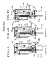
- Fig. 4A is a side view illustrating a condition where a presser bar lifting lever of a known sewing machine is in a lower position
- Fig. 4B is a side view illustrating a condition where the presser bar lifting lever of the known sewing machine holds a presser bar in a first holding position
- Fig. 4C is a side view illustrating a condition where the presser bar lifting lever of the known sewing machine holds the presser bar in a position located further upward than the first holding position;
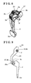
- Fig. 5 is a perspective view of the presser bar lifting lever of the known sewing machine
- Fig. 6A is an explanation diagram describing a movement of a pair of thread tension disks of the sewing machine according to the embodiment
- Fig. 6B is an explanation diagram describing the movement of the pair of thread tension disks of the sewing machine according to the embodiment
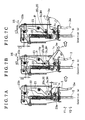
- Fig. 7A is a side view illustrating a condition where the presser bar lifting lever of the sewing machine according to the embodiment disclosed here holds the presser bar in a lower position;
- Fig. 7B is a side view illustrating a condition where the presser bar lifting lever of the sewing machine according to the embodiment disclosed here holds the presser bar in the first holding position;
- Fig. 7C is a side view illustrating a condition where the presser bar lifting lever of the sewing machine according to the embodiment disclosed here holds the presser bar in the second holding position;
- Fig. 8 is a perspective view of the presser bar lifting lever of the sewing machine according to the embodiment disclosed here;
- Fig. 9 is an explanation diagram describing a condition where a thread tension adjustment cam portion of the presser bar lifting lever and a thread tension releasing portion are in contact with each other;
- Fig. 10A is a side view explaining a detecting function of a switch and illustrating a positional relation between a switch lever and a leaf switch of the switch when the presser bar lifting lever is in the lower position;
- Fig. 10B is a side view explaining the detecting function of the switch and illustrating the positional relation between the switch lever and the leaf switch of the switch when the presser bar lifting lever is lever is in the first holding position;
- Fig. 10C is a side view explaining the detecting function of the switch and illustrating the positional relation between the switch lever and the leaf switch of the switch when the presser bar lifting lever is in the second holding position;
- Fig. 11 is a graph illustrating a relation between an rotation angle of the presser bar lifting lever and a vertical movement distance of the presser bar and a relation between the rotation angle of the presser bar lifting lever and an opening angle between the pair of thread tension disks;
- Fig. 12A is an explanation drawing describing a function of a stopper and illustrating the stopper under a condition where the presser foot is attached to the presser bar;
- Fig. 12B is an explanation drawing describing the function of the stopper and illustrating the stopper under a condition where the presser foot is detached from the presser bar;
- Fig. 13 is an explanation diagram illustrating a rod operable together with an automatic thread tension disk opening/closing mechanism.
- FIGs. 1 to 3 illustrate a condition where a presser bar lifting lever 3 for a presser bar 5 of the sewing machine according to the embodiment is attached to a main body 1 of the sewing machine.
- the presser bar lifting lever 3 has a lock mechanism to hold or lock the presser bar 5 in two positions (first and second holding positions (see Figs. 7A and 7B ). As shown in Figs.
- the main body 1 includes a needle bar 51 to which a sewing needle 50 is attached.
- the presser bar lifting lever 3 includes an operation portion 3w manually rotated by a user of the sewing machine. Further, the presser bar lifting lever 3 is attached to a rotary shaft 1 c extending forward from the main body 1 in the longitudinal direction, thereby being movable along a vertical direction of the main body 1.
- a thread tension releasing portion 23 having an arm shape is attached to the main body 1 by a retaining ring 24 so as to be rotate about a shaft 1b.
- the thread tension releasing portion 23 will be hereinafter referred to as a thread tension releasing arm 23.
- the thread tension releasing arm 23 transmits a lift amount of a height adjustment cam portion 3H of the presser bar lifting lever 3 to a thread tension releasing operation member 12.
- the thread tension releasing arm 23 includes a contact portion 23b at an upper end.
- the thread tension releasing operation member 12 having an arm shape and transmitting the rotation of the thread tension releasing arm 23 to a needle thread tension adjustment mechanism 9 is attached to the main body 1 by a retaining ring 32r so as to be rotate about a shaft 1a along the horizontal direction of the sewing machine, i.e. along thread tension releasing directions indicated by arrows X5 and X6 in the horizontal direction.
- a pair of thread tension disks 13b and 13c (first and second thread tension disks) of the needle thread tension adjustment mechanism 9 is located in adjacent to a contact portion 12a at a first end of the thread tension releasing operation member 12.
- the thread tension releasing operation member 12 is pressed by the contact portion 23b of the thread tension releasing arm 23 and thereby rotates about the shaft 1 a by a rotation angle E1 in thread tension releasing directions indicated by arrows X5 and X6. Then, the rotating operation of the thread tension releasing arm 23 is transmitted to the first thread tension disk 13b, which is adjacent to the thread tension releasing operation member 12, therefore separating the first thread tension disk 13b from the second thread tension disk 13c and moving the first thread tension disk 13b in a direction indicated by an arrow X7 corresponding to a thread tension releasing direction. As illustrated in Fig.
- a return spring 14 for returning the thread tension releasing operation member 12 to an initial position is hooked at a second end of the thread tension releasing operation member 12.
- the contact portion 12a of the thread tension releasing operation member 12 is biased by a biasing force of the return spring 14 in a direction in which the contact portion 12a separates from the first thread tension disk 13b (the direction is an opposite direction from the thread tension releasing direction of the arrow X6).
- the presser bar 5 extending in the vertical direction is attached to the main body 1 by a bearing support plate 28 and a bolt 27 while penetrating through a spherical bearing 29 along the vertical direction.
- a presser bar holding member 20 including a contact portion 20c is fixed to the presser bar 5 by means of a screw 21.
- a presser spring 22 and a presser bar support plate 25 are attached to an upper portion of the presser bar 5.
- the presser bar support plate 25 is fixed to the main body 1 by means of a screw 26.
- the contact portion 20c of the presser bar holding member 20 fixed to the presser bar 5 so as to be integrated therewith is biased in a downward direction (indicated by an arrow Y2 in Fig. 3 ) by a biasing force of the presser spring 22.
- the contact portion 20c of the presser bar holding member 20 is contactable with first and second cam surfaces 3c and 3d of the height adjustment cam portion 3H of the presser bar lifting lever 3 as will be described below.
- the sewing machine includes a presser foot 6 utilized to press a workpiece fabric from an upper side of the presser bar 5 relative to a needle plate 2 when the sewing machine operates in a normal sewing mode.
- a holder 4 combined with the presser foot 6 is detachably fixed to a lower end 5d of the presser bar 5 by means of a screw 34.
- the screw 34 is removed from the presser bar 5
- the presser foot 6 and the holder 4 may be detached from the presser bar 5.
- the user of the sewing machine removes the presser foot 6 and the holder 4 from the presser bar 5.
- Such procedures are conducted in order to avoid interference between an embroidery frame and the presser foot 6.
- an external thread is formed at an upper portion of a stopper 7 (embroidery restriction member) extending in the vertical direction and having a shaft shape.
- An upper end of the stopper 7 is fixed to the main body 1 by means of an adjustment nut 35 while the external thread of the stopper 7 is screwed with an internal thread at a lower surface 1 u of the main body 1 (see Figs. 12A and 12B ).
- the stopper 7 is rotated about an axis while meshing with the internal thread of the lower surface 1 u of the main body 1 along the vertical direction; thereby, a length of the stopper 7 protruding downward from the lower surface 1 u of the main body 1 in the vertical direction may be adjusted (the length of the stopper 7 corresponds to a distance LA between a lower end 7a of the stopper 7 and an upper surface 4a of the holder 4 illustrated in Fig. 1 ).
- a leaf switch 18 having an intermediate contact point 18a is fixed to a switch base 16 by means of a screw 33.
- the leaf switch 18, a switch lever 15, the switch base 16 that constitutes a portion of a switch unit are attached to one another.
- a switch is formed by the leaf switch 18, the switch lever 15, and the switch base 16.
- the switch lever 15 is attached to the main body 1 so as to rotate about a shaft 16a of the switch base 16 in a condition where the switch lever spring 17 formed by a torsion coil spring having first and second arms for returning the switch lever 15 to an initial position is arranged between the switch lever 15 and the switch base 16.
- the first arm of the switch lever spring 17 is hooked to the switch base 16 while the second arm of the switch lever spring 17 is hooked to the switch lever 15; thereby, the switch lever 15 is biased in a first direction indicated by an arrow R2 shown in Fig. 3 and corresponding to a clockwise direction in Fig. 3 .
- the switch unit attached to the switch base 16 is fixed to a back surface of the main body 1 by means of a screw 19.
- the switch lever 15 includes an operation bore 15a having an elongated shape.
- a switch lever operation arm 3f of the presser bar lifting lever 3 is fitted to the operation bore 15a (see Figs. 8 and 10 ); thereby, the switch lever 15 rotates along with the presser bar lifting lever 3.
- the switch lever 15 when the presser bar lifting lever 3 is rotatably operated about the rotary shaft 1 c, the switch lever 15 rotates in the same direction as the presser bar lifting lever 3 rotates.
- the switch lever 15 includes first and second operation arms 15b and 15c facing each other so as to sandwich therebetween the intermediate contact point 18a of the leaf switch 18.
- the first operation arm 15b and the second operation arm 15c of the switch lever 15 are not in contact with the intermediate contact point 18a of the leaf switch 18.
- a switch including one circuit and two contact points may be applied to the aforementioned switch at which the switch lever 15 rotates along with the rotation of the presser bar lifting lever 3.
- the switch lever 15 may rotate in a clockwise or counterclockwise direction and may move to an intermediate position in a movable range of the switch lever.
- the switch may be configured to close the contact portions (output three types of signals).
- a control unit may include a program selecting a sewing pattern related only to the normal sewing mode when the signal corresponding to the clockwise or counterclockwise rotation of the switch lever 15 is outputted. Further the program selects a sewing pattern related only to an embroidery mode.
- the sewing machine according to the embodiment is applied as a sewing machine by which the user of the sewing machine may do embroidery, freehand embroidery, or the like. Accordingly, as illustrated in Fig. 1 , in addition to components described above, an automatic thread tension disk opening/closing mechanism 10 is arranged on the sewing machine.
- the automatic thread tension disk opening/closing mechanism 10 automatically releases a needle thread tension by means of a motor 10c, for example, when the sewing machine operates in the embroidery mode.
- a rod 11 is pulled in a thread tension releasing direction (indicated by an arrow X5 in Fig. 13 ) by an operating force of the motor 10c of the automatic thread tension disk opening/closing mechanism 10 and the operating force of the motor 10c is transmitted by the rod 11 to the thread tension releasing operation member 12.
- the thread tension releasing operation member 12 rotates about the rotary shaft 1a by the rotation angle E1 toward the thread tension releasing directions of the arrows X5 and X6 as seen in Figs. 6A and 6B ; thereby, the first thread tension disk 13b separates from the second thread tension disk 13c. As a result, the needle thread tension adjustment mechanism 9 is brought into an inactive mode to thereby loosen the needle thread tension.
- Figs. 4A, 4B, 4C , and 5 illustrate a mechanism of a presser bar lifting lever 30 of a known sewing machine.
- the presser bar lifting lever 30 (corresponding to the presser bar lifting lever 3 in the embodiment) and a thread tension releasing arm 31 (corresponding to the thread tension releasing arm 23 in the embodiment) are applied to the known sewing machine.
- the presser bar lifting lever 30 includes cam surfaces 30a and 30c for adjusting a position of the presser bar lifting lever 30 in a vertical direction of the known sewing machine, and a cam surface 30b for adjusting a needle thread tension.
- a clearance A4 is generated between the cam surface 30a of the presser bar lifting lever 30 and the presser bar holding member 20, that is, the cam surface 30a of the presser bar lifting lever 30 is not in contact with the presser bar holding member 20.
- a lift amount of the cam surface 30b of the presser bar lifting lever 30 may be transmitted by a contact portion 31 b at an upper end of the thread tension releasing arm 31, via a contact portion 31a at a lower end of the tension releasing arm 31 making contact with the presser bar lifting lever 30, to the thread tension releasing operation member 12.
- a clearance D1 is generated (refer to a condition (a) illustrated in Fig.
- the known sewing machine may be operated in the normal sewing mode by the user when the presser bar lifting lever 30 is in the condition (a) of Fig. 4A .
- the user rotates the presser bar lifting lever 30 upward by a rotation angle B1 as the condition (a) of Fig. 4A shifts to a condition (b) illustrated in Fig. 4B .
- the presser bar holding member 20 is lifted up by the cam surface 30c of the presser bar lifting lever 30 in accordance with a lift amount of the cam surface 30a of the presser bar lifting lever 30, therefore moving the presser bar holding member 20 and the presser bar 5 in an upward direction indicated by an arrow Y1 in Fig. 4A .
- the user of the known sewing machine may desirably position a workpiece fabric such as a fabric to be embroidered, on the needle plate 2 while the needle thread tension is not released.
- the user rotates the presser bar lifting lever 30 further upward by a maximum rotation angle C1 shown in Fig. 4C as the condition (b) of Fig. 4B shifts to a condition (c) illustrated in Fig. 4C .
- the presser bar holding member 20 is moved upward along with the presser bar 5 in accordance with the lift amount of the cam surface 30a of the presser bar lifting lever 30 toward the upward direction of the arrow Y1.
- the upper end of the presser bar 5 is moved further upward by a distance C2 from the lower position to a position shown in Fig. 4C .
- the lift amount of the cam surface 30b does not vary from the condition (b) of Fig. 4B ; therefore, the needle thread tension adjustment mechanism 9 is maintained in the inactive mode; therefore, the needle thread tension remains loosened.
- the cam surface 30a of the presser bar lifting lever 30 does not have a flat surface; therefore, the presser bar holding member 20 may not be maintained in the position shown in Fig. 4C and thereby moves downward.
- the user of the known sewing machine inserts the workpiece fabric under the presser foot 6.
- the presser bar lifting lever 30 is moved upward by the distance B2 only; therefore, the user of the known sewing machine may not easily place the workpiece fabric under the presser foot 6.
- the user of the known sewing machine moves the presser bar 5 and the presser foot 6 upward approximately by the distance C2 from the lower position of Fig. 4A to the position of Fig. 4C so as to easily place the workpiece fabric under the presser foot 6, thereby increasing the sewing efficiency.
- the known sewing machine is configured as described above to automatically return the presser bar 5 and the presser foot 6 from the position of Fig. 4C to the first holding position of Fig. 4B , thereby preventing the aforementioned damage of the presser foot 6 due to the contact with the needle clamp 8.
- the presser bar lifting lever 30 is maintained in the first holding position of Fig.
- the user may not easily place the embroidery frame under the presser foot 6 and the first thread tension disk 13b is separated from the second thread tension disk 13c. Accordingly, the user of the known sewing machine needs to move the presser bar lifting lever 30 downward so as to appropriately operate the sewing machine in the embroidery mode; however, the user of the sewing machine may forget to lift down the presser foot lifting lever 30 before doing embroidery.
- the presser bar lifting lever 30 is configured to automatically return from the condition (c) of Fig. 4C to the condition (b) of Fig. 4B , thereby preventing the user of the sewing machine from forgetting to lift down the presser foot lifting lever 30 before doing embroidery.
- Fig. 8 illustrates the presser bar lifting lever 3 according to the embodiment.
- the presser bar lifting lever 3 includes the height adjustment cam portion 3H for adjusting the position of the presser bar 5 in the vertical direction and the position of the presser foot 6 in the vertical direction, and a thread tension adjustment cam portion 3T for allowing the needle thread tension adjustment mechanism 9 to adjust the needle thread tension.
- the height adjustment cam portion 3H and the thread tension adjustment cam portion 3T are formed at different portions of the presser bar lifting lever 3 as illustrated in hatched areas in Fig. 8 .
- the height adjustment cam portion 3H and the thread tension adjustment cam portion 3T are arranged at an opposite side from the operation portion 3w manually operated by the user of the sewing machine in the vertical direction.
- the presser bar lifting lever 3 includes the switch lever operation arm 3f extending in the longitudinal direction of the main body 1.
- a cam profile of the height adjustment cam portion 3H includes a neutral cam surface 3a for arranging the presser bar 5 in a lower position (see Fig.
- a cam profile of a cam surface 3b of the thread tension adjustment cam portion 3T of the presser bar lifting lever 3 functions as follows: (a) When the presser bar 5 is in the lower position, the cam profile of the cam surface 3b of the thread tension adjustment cam portion 3T brings the needle thread tension adjustment mechanism 9 into the active mode and allows the first thread tension disk 13b to be closed relative to the second thread tension disk 13c, in order for the sewing machine to be operable in the normal sewing mode; (b) When the presser bar 5 is maintained in the first holding position, the cam profile of the cam surface 3b of the thread tension adjustment cam portion 3T brings the needle thread tension adjustment mechanism 9 into the inactive mode to thereby release the needle thread tension; and (c) When the presser bar 5 is maintained in the second holding position, the cam profile of the cam surface 3b of the thread tension adjustment cam portion 3T brings the needle thread tension adjustment mechanism 9 into the active mode and allows the first tension disk 13b to be closed relative to the second thread tension disk 13c, in order for the sewing machine to be operable in
- Fig. 7A illustrates a condition (a) where the presser bar lifting lever 3 is manually rotated down by the user of the sewing machine around the rotary shaft 1c.
- the presser bar 5 in the condition where the presser foot 6 is attached to the presser bar 5 (the sewing machine is in the normal sewing mode), the presser bar 5 is biased by the biasing force of the presser spring 22 toward a downward direction indicated by an arrow Y2 and the presser foot 6 is pressed against the needle plate 2. Accordingly, a clearance A4 is generated between the neutral cam surface 3a of the height adjustment cam portion 3H of the presser bar lifting lever 3 and the contact portion 20c of the presser bar holding member 20 (refer to the condition (a) of Fig. 7A ).
- a contact portion 23a of the thread tension releasing arm 23 may make contact with the presser bar lifting lever 3 and the thread tension releasing arm 23 is moved in a thread tension releasing direction (indicated by an arrow X5 in Fig. 9 ) in accordance with a lift amount of the cam surface 3b of the thread tension adjustment cam portion 3T of the presser bar lifting lever 3. That is, the lift amount of the cam surface 3b of the thread tension adjustment cam portion 3T of the presser bar lifting lever 3 is transmitted via the contact portion 23b of the thread tension releasing arm 23 to the thread tension releasing operation member 12.
- the clearance D1 is generated between the operating point 13a of the first thread tension disk 13b and the contact portion 12a of the thread tension releasing operation member 12 (refer to Fig. 6A ).
- the first thread tension disk 13b is closed relative to the second thread tension disk 13c; thereby, the needle thread tension adjustment mechanism 9 is in the active mode. Consequently, the sewing machine may be operated in the normal sewing mode by the user under the condition (a) of Fig. 7A (the sewing machine may be operated in the normal sewing mode by the user in the same way as the known sewing machine).
- the first cam surface 3c having a flat surface is in contact with the contact portion 20c of the presser bar holding member 20.
- the first cam surface 3c is positioned on a straight line P passing through a central axis of the rotary shaft 1c so as to be perpendicular to the central axis as illustrated in the condition (b) of Fig. 7B .
- the first cam surface 3c extends along a horizontal direction in Fig. 7B . Accordingly, a downward force FM due to the biasing force of the presser spring 22 substantially acts along the straight line P. Consequently, in the condition (b) of Fig. 7B , a moment to rotate the presser bar lifting lever 3 downward about the rotary shaft 1 c is not substantially generated.
- the contact portion 23a makes contact with the presser bar lifting lever 3 and the thread tension releasing arm 23 rotates in the thread tension releasing direction of the arrow X5 in accordance with the lift amount (a section 3e illustrated in Fig. 9 ) of the cam surface 3b of the thread tension adjustment cam portion 3T of the presser bar lifting lever 3.
- the lift amount of the cam surface 3b of the thread tension adjustment cam portion 3T of the presser bar lifting lever 3 is transmitted to the thread tension releasing operation member 12 via the contact portion 23b that is in the opposite direction from the contact portion 23a in the vertical direction.
- the thread tension releasing operation member 12 rotates about the rotary shaft 1a by a rotation angle E1 in the thread tension releasing direction indicated by the arrow X5 in Fig. 5 and by the arrow X5 in Fig. 13 . Consequently, as seen from Figs. 6A and 6B , the contact portion 12a of the thread tension releasing operation member 12 presses the operating point 13a of the first thread tension disk 13b in the thread tension releasing direction of the arrow X6; thereby, the first thread tension disk 13b separates from the second thread tension disk 13c and therefore has the opening angle E2 relative to the second thread tension disk 13c. As a result, the needle thread tension adjustment mechanism 9 is allowed to loosen the needle thread tension.
- the user of the sewing machine may desirably position the workpiece fabric to be embroidered, on the needle plate 2 (the presser bar lifting lever 3 in the condition (b) of Fig. 7B functions in the same way as in the presser bar lifting lever 30 in the condition (b) of Fig. 4B ).
- the sewing machine according to the embodiment differs from the known sewing machine as follows.
- the user of the sewing machine manually rotates the presser bar lifting lever 3 about the rotary shaft 1 c further upward (by a maximum rotation angle C1) as the condition (b) of Fig. 7B shifts to a condition (c) illustrated in Fig. 7C .
- the contact portion 20c of the presser bar holding member 20 and the presser bar 5 move further upward (toward the upward direction of the arrow Y1) in accordance with a lift amount of the second cam surface 3d of the height adjustment cam portion 3H of the presser bar lifting lever 3; thereafter, the second cam surface 3d having a flat surface makes contact with the contact portion 20c of the presser bar holding member 20.
- the second cam surface 3d is positioned on the straight line P passing through the central axis of the rotary shaft 1 c of the presser bar lifting lever 3 so as to be perpendicular to the central axis.
- the second cam surface 3d extends along a horizontal direction in Fig. 7C . Accordingly, the downward force FM due to the biasing force of the presser spring 22 substantially acts along the straight line P. Consequently, the moment to rotate the presser bar lifting lever 3 downward about the rotary shaft 1c is not substantially generated. As a result, the presser bar 5 is moved upward by a distance C2 from the lower position in Fig. 7A to the second holding position in Fig. 7C and is thereafter maintained thereat. In the condition (c) of Fig. 7C , the presser bar lifting lever 3 is moved further upward from the condition (b) of Fig.
- the user of the sewing machine may do embroidery, freehand embroidery, or the like by using the embroidery frame in the condition (c) of Fig. 7C (the function of the presser bar lifting lever 3 of the sewing machine in the condition (c) of Fig. 7C is different from the function of the presser bar lifting lever 30 of the known sewing machine in the condition (c) of Fig. 4C ).
- the position of the presser bar lifting lever 3 in each of Figs. 10A to 10C corresponds to the position of the presser bar lifting lever 3 in each of the Fig. 7A to 7C .
- the switch lever 15 including the operation bore 15a is attached to the main body 1 so as to rotate about the rotary shaft 16a that is arranged at a different position from the rotary shaft 1 c.
- the operation bore 15a is formed so as to have the elongated shape.
- the switch lever operation arm 3f integrally formed with the presser bar lifting lever 3 is fitted to the operation bore 15a.
- the switch outputs an ON signal 1 (first ON signal) to a control unit.
- ON signal 1 first ON signal
- the clearance A4 between the neutral cam surface 3a of the height adjustment cam portion 3H of the presser bar lifting lever 3 and the contact portion 20c of the presser bar holding member 20 increases; therefore, the presser bar lifting lever 3 may easily move upward.
- the switch lever spring 17 biasing the switch lever 15 toward the first direction of the arrow R2 is provided in order to prevent the disconnection between the leaf switch 18 and the switch lever 15.
- the switch lever spring 17 may be formed by any member as long as serving as an elastic body.
- the first operation arm 15b and the second operation arm 15c of the switch lever 15 are not in contact with the intermediate contact point 18a while not pressing the intermediate contact point 18a. Accordingly, the leaf switch 18 is not electrically connected to the switch lever 15; therefore, the switch outputs an OFF signal to the control unit.
- the presser bar lifting lever 3 is rotated about the rotary shaft 1c by a rotation angle C1 from the condition (b) of Fig. 10B . Accordingly, the operation bore 15a is moved further upward by the switch lever operation arm 3f compared to the condition (b) of Fig. 10B .
- the operation bore 15a has the elongated shape; thereby, the switch lever operation arm 3f moves along the operation bore 15a. Accordingly, the switch lever 15 rotates against the biasing force of the switch lever spring 17 toward the second direction of the arrow R1.
- the switch outputs the ON signal 1, the OFF signal, and the ON signal 2 for the lower position, the first holding position, and the second holding position of the presser bar lifting lever 3, respectively.
- the ON signal 1, the OFF signal, and the ON signal 2 are input to a microcomputer of the main body 1 of the sewing machine and are thereafter processed by the microcomputer.
- the sewing machine operates in modes shown in Table 1.
- Fig. 11 is a chart showing a relation between a rotation angle of the presser bar lifting lever 3 and a vertical movement distance of the presser bar 5 and the presser foot 6 and a relation between the rotation angle of the presser bar lifting lever 3 and an opening angle of the first thread tension disk 13b relative to the second thread tension disk 13c.
- a characteristic curved line B1 indicates the vertical movement distance of the presser bar 5 and the presser foot 6 of the sewing machine according to the embodiment.
- a characteristic curved line B2 indicates the vertical movement distance of the presser bar 5 and the presser foot 6 of the known sewing machine.
- a characteristic line C1 indicates the opening angle of the first thread tension disk 13b relative to the second thread tension disk 13c according to the sewing machine of the embodiment.
- a characteristic line C2 indicates the opening angle of the first thread tension disk 13b relative to the second thread tension disk 13c according to the known sewing machine.
- the first holding position to which the presser bar 5 and the presser foot 6 are moved upward from the lower position is indicated by a point F2. Further, the position located further upward than the first holding position (the position corresponding to the second holding position to which the presser bar 5 and the presser foot 6 of the sewing machine of the embodiment is moved further upward from the first holding position) is indicated by a point F3. Meanwhile, according to the sewing machine of the embodiment, as shown by the characteristic curved line B1 in Fig. 11 , the first holding position to which the presser bar 5 and the presser foot 6 are moved upward from the lower position is indicated by a point F1.
- the position to which the presser bar 5 and the presser foot 6 are moved further upward from the first holding position is indicated by the point F3.
- the presser bar 5 and the presser foot 6 are maintained in both the first holding position of the point F1 and the second holding position of the point F3 so as not to move downward due to gravity.
- the first thread tension disk 13b separates from the second thread tension disk 13c so as to have therebetween the opening angle E2 until the presser bar 5 and the presser foot 6 are moved upward from the lower position to the first holding position of the point F2 and are maintained thereat.
- the first thread tension disk 13b remains separated from the second thread tension disk 13c while keeping the opening angle E2 to the second thread tension disk 13c.
- the first thread tension disk 13b separated from the second thread tension disk 13c is closing toward the second thread tension disk 13c for a period of time tc while the position of the presser bar 5 and the presser foot 6 shifts from the first holding position of the point F1 to the second holding position of the point F3.
- the embroidery frame is prevented from making contact with the presser bar 5.
- the embroidery frame is prevented from making contact with the presser bar 5.
- the stopper 7 (embroidery restriction member) having an extended shaft shape is arranged at the lower surface 1 u of the main body 1 so as to protrude downward from the lower surface 1 u as described above.
- a height from the needle plate 2 to the lower end 7a of the stopper 7 is adjustable; however, the stopper 7 is designed so that the lower end 7 is positioned higher than the position of the lower end 5d of the presser bar 5 in the vertical direction.
- the position of the lower end 7a of the stopper 7 in the vertical direction is adjusted so as to make contact with the upper surface 4a of the holder 4 for the presser foot 6 before the presser bar lifting lever 3 is maintained in the second holding position (before the presser bar lifting lever 3 shifts to the condition (c) in Fig. 7C ).
- the user of the sewing machine intends to operate the sewing machine in the embroidery mode under a condition (a) illustrated in Fig. 12A where the holder 4 and the presser foot 6 are attached to the presser bar 5
- the user of the sewing machine rotates the presser bar lifting lever 3 upward so as to move the presser bar 5 in an upward direction (indicated by an arrow Y1) and to hold the presser bar 5 in the second holding position.
- the presser foot 6 may be prevented from making contact with the embroidery frame and the needle clamp 8 may be prevented from making contact with the presser foot 6.
- the presser foot 6 may be configured to make contact with the lower end 7a of the stopper 7 instead of the holder 4.
- the thread tension releasing operation member 12 rotates about the rotary shaft 1a.
- the contact portion 23b of the thread tension releasing arm 23 is moved in the thread tension releasing direction (indicated by an arrow X5) by the thread tension adjustment cam portion 3T of the presser bar lifting lever 3 (refer to Fig. 9 ).
- the thread tension releasing operation member 12 rotates about the rotary shaft 1a in thread tension releasing directions (indicated by arrows X5 and X6); therefore, the contact portion 12a moves the operating point 13a of the first thread tension disk 13b in the thread tension releasing direction of the arrow X6.
- the first thread tension disk 13b separates from the second thread tension disk 13c to release the needle thread tension accordingly.
- the user of the sewing machine manually rotates the presser bar lifting lever 3 upward to thereby release the needle thread tension.
- a shaft 12b serving as a protruding portion is arranged at the thread tension releasing operation member 12.
- the rod 11 formed to extend from the automatic thread tension disk opening/closing mechanism 10 is attached to the thread tension releasing operation member 12.
- An elongated bore 11a extending in a longitudinal direction of the rod 11 is formed therein in the vicinity of the thread tension releasing operation member 12.
- the shaft 12b of the thread tension releasing operation member 12 is fitted to the elongated bore 11a so as to move therealong in the longitudinal direction.
- the shaft 12b of the thread tension releasing operation member 12 is movable in the free space 11 x along the longitudinal direction of the rod 11 and is normally positioned close to a wall portion 11y arranged at one of sides of the rod 11 in the longitudinal direction (positioned in the vicinity of the thread tension releasing operation member 12).
- the automatic thread tension disk opening/closing mechanism 10 operates so as to separate the first thread tension disk 13b from the second thread tension disk 13c under a condition where the sewing machine is in the embroidery mode or the like. Then, the rod 11 moves in the thread tension releasing direction of the arrow X5 and the shaft 12b of the thread tension releasing operation member 12 is pulled by the wall portion 11y in the thread tension releasing direction of the arrow X5; therefore, the thread tension releasing operation member 12 rotates about the rotary shaft 1a toward the thread tension releasing directions of the arrow X5 and the arrow X6.
- the contact portion 12a of the thread tension releasing operation member 12 moves the operating point 13a of the first thread tension disk 13b in the thread tension releasing direction of the arrow X6 and the first thread tension disk 13b separates from the second thread tension disk 13c.
- the needle thread tension is released.
- the motor 10c of the automatic thread tension disk opening/closing mechanism 10 is driven to pull the rod 11 in the thread tension releasing direction of the arrow X5, thereby automatically releasing the needle thread tension.
- the thread tension releasing operation member 12 appropriately rotates about the rotary shaft 1a toward the thread tension releasing directions of the arrows X5 and X6 and the needle thread tension may be automatically released by the automatic thread tension disk opening/closing mechanism 10.
- the manual operation of the presser bar lifting lever 3 by the user of the sewing machine in a condition where the first thread tension disk 13b is not separated from the second thread tension disk 13c by the automatic thread tension disk opening/closing mechanism 10, i.e. in a condition where the rod 11 is not pulled in the thread tension releasing direction of the arrow X5 by the automatic thread tension disk opening/closing mechanism 10, will be explained as follows.
- the contact portion 23b of the thread tension releasing arm 23 is moved in the thread tension releasing direction of the arrow X5 by the thread tension adjustment cam portion 3T of the presser bar lifting lever 3 as illustrated in Fig. 13 .
- the contact portion 12a of the thread tension releasing operation member 12 rotates about the rotary shaft 1a in the thread tension releasing direction of the arrow X6 and thereby moves the operating point 13a of the thread tension disk 13 in the thread tension releasing direction of the arrow X6. Accordingly, the first thread tension disk 13b separates from the second thread tension disk 13c, therefore releasing the needle thread tension.
- the shaft 12b of the thread tension releasing operation member 12 moves from the wall portion 11 y to the free space 11 x in the elongated bore 11 a along the longitudinal direction.
- the user of the sewing machine when operating the sewing machine in the embroidery mode, the freehand embroidery mode, or the like by means of the embroidery frame, the user of the sewing machine manually rotates the presser bar lifting lever 3 upward to allow the presser bar 5 to be maintained in the second holding position. Accordingly, an upper surface of the embroidery frame does not make contact with the lower end 5d of the presser bar 5 in the vertical direction.
- the needle thread tension adjustment mechanism 9 when the presser bar 5 is maintained in the second holding position, the needle thread tension adjustment mechanism 9 is in the active mode and the first thread tension disk 13b is closed relative to the second thread tension disk 13c, therefore allowing the user of the sewing machine to appropriately do freehand embroidery by using the needle thread.
- the aforementioned effect according to the embodiment is realized by a mechanical mechanism without addition of an actuator and may be obtained at low cost.
- the needle thread tension adjustment mechanism 9 does not shift to the active mode and the needle thread tension remains loosened.
- the lower end 5d of the presser bar 5 is positioned in such a manner to contact the upper surface of the embroidery frame in the vertical direction. Accordingly, when doing embroidery, freehand embroidery, or the like, the user of the sewing machine needs to be careful so that the upper surface of the embroidery frame does not make contact with the lower end 5d of the presser bar 5 in the vertical direction.
- the switch may detect three rotational positions of the presser bar lifting lever 3 such as the lower position, the first holding position, and the second holding position.
- the sewing machine In a condition where the presser bar lifting lever 3 is moved down by the user of the sewing machine to the lower position, the sewing machine is operable in the normal sewing mode and may select the sewing pattern related only to the normal sewing mode. Further, in a condition where the presser bar lifting lever 3 is moved by the user of the sewing machine to the second holding position and is maintained thereat, the swing machine is operable in the embroidery mode and the user may select the sewing pattern related only to the embroidery mode, the freehand embroidery mode, or the like. Accordingly, usability and safety of the user of the sewing machine may increase.
- the sewing machine is not operable in the same way as the known sewing machine; thereby, the safety of the user of the sewing machine may be maintained.
- Such effect may be realized by the simply configured switch and the mechanical mechanism; therefore, the inexpensive sewing machine may be obtained.
- a switch is applied to thereby detect two rotational positions of the presser bar lifting lever 30.
- the presser bar lifting lever 3 may not be moved upward to the second holding position and may not be maintained thereat; therefore, the user of the sewing machine may not shift the sewing machine from the normal sewing mode to the embroidery mode.
- the user of the sewing machine may not operate the sewing machine in the embroidery mode, the freehand embroidery mode, or the like in a condition where the presser foot 6 is accidentally attached to the lower end 5d of the presser bar 5 by the user of the sewing machine.
Landscapes
- Engineering & Computer Science (AREA)
- Textile Engineering (AREA)
- Sewing Machines And Sewing (AREA)
Abstract
Description
- This disclosure relates to a sewing machine having a presser bar vertically movable and holding a presser foot.
- A known presser bar lifting mechanism for a sewing machine disclosed in
JP2001-190878A - A known embroidery presser (darning presser) for an embroidery machine is disclosed in
JP 2006-263170A - A sewing machine and a presser foot bar lifting device for the same are disclosed in
JP2009-112325A Reference 3, a presser foot lifting lever may rotate from an axial direction of a presser bar toward a right side in a horizontal direction seen from a user of the sewing machine and toward a rear side in a longitudinal direction seen from the user of the sewing machine. Accordingly, when moving the presser foot lifting lever upward and downward, the user of the sewing machine may rotate the presser foot lifting lever toward the right side and the rear side depending on his/her using conditions of the sewing machine. Consequently, when the user of the sewing machine sews a workpiece fabric by means of the sewing machine, the presser foot lifting lever does not interfere with the workpiece fabric. In addition, the operability of the presser bar lifting lever may not deteriorate. - According to the presser bar lifting mechanism described in
Reference 1, the solenoid is utilized to the sewing machine in order to move the presser foot and the presser bar upward. Accordingly, for example, when the sewing machine is switched off, the presser foot and the presser bar are not maintained in the respective upward positions and are moved downward by the biasing force of the presser foot spring. In addition, the solenoid and the control unit are utilized in the sewing machine in order to move the presser foot and the presser bar upward, therefore increasing the cost of the sewing machine compared to a domestic manual sewing machine including a manual operated presser bar lifting lever. - According to the presser foot described in
Reference 2, in a condition where the presser lifting operation lever is moved upward by the user of the embroidery machine (in a condition where the user of the embroidery machine attaches and detaches the embroidery frame to and from the embroidery frame transferring device), the embroidery frame and the presser foot of the embroidery presser do not make contact with each other in the vertical direction. However, when the presser lifting operation lever is moved downward in a condition where the user of the embroidery machine does embroidery by means of the embroidery machine, the embroidery frame and the presser foot may make contact with each other. In addition, the user of the embroidery machine may do embroidery by not using the presser foot but by using the embroidery frame only. However, according to the embroidery machine ofReference 2, even in a case where the user does embroidery by not using the presser foot but by using the embroidery frame, the embroidery frame and the presser bar may make contact with each other in the vertical direction. - According to
Reference 3, in a case where the user of the sewing machine uses an embroidery frame when doing freehand embroidery by means of the sewing machine, the presser foot lifting lever does not make contact with the embroidery frame in a vertical direction of the sewing machine while the presser bar (from which the presser foot is detached) may make contact with the embroidery frame. Further, the presser foot lifting lever does not include a cam adjusting an opening angle between a pair of thread tension disks. In addition, the cam adjusting the opening angle between the pair of thread tension disks rotates about an axis of the presser bar; therefore, it is difficult for such cam to be arranged at the presser foot lifting lever. As a result, the presser foot bar lifting device configured at low cost may not allow the presser bar lifting lever to operate in synchronization with the adjustment of the opening angle between the pair of thread tension disks. - A need thus exists for a sewing machine that is simply configured so that a presser bar is maintained in first and second holding positions in accordance with a manual operation of a presser bar lifting lever by a user of the sewing machine.
- According to an aspect of this disclosure, a sewing machine includes a main body, a presser bar attached to the main body so as to move along a vertical direction of the sewing machine and detachably holding a presser foot at a lower end, a needle thread tension adjustment mechanism selectively brought into inactive and active modes, the needle thread tension adjustment mechanism releasing a needle thread tension in the inactive mode and maintaining the needle thread tension in the active mode, and a presser bar lifting lever manually rotated about a rotary shaft along the vertical direction by a user of the sewing machine and provided so as to adjust a position of the presser bar in the vertical direction in accordance with the manual rotation, the presser bar lifting lever including a height adjustment cam portion adjusting the position of the presser bar in the vertical direction and a thread tension adjustment cam portion allowing the needle thread tension adjustment mechanism to adjust the needle thread tension, wherein the height adjustment cam portion of the presser bar lifting lever includes a cam profile arranging the presser bar in a lower position in which the sewing machine is operable in a normal sewing mode, the cam profile of the height adjustment cam portion allowing the presser bar to be maintained in a first holding position to which the presser bar is moved further upward from the lower position in the vertical direction, the cam profile of the height adjustment cam portion allowing the presser bar to be maintained in a second holding position to which the presser bar is moved further upward from the first holding position in the vertical direction, and wherein the thread tension adjustment cam portion of the presser bar lifting lever includes a cam profile bringing the needle thread tension adjustment mechanism into the active mode when the presser bar is in the lower position, the cam profile of the thread tension adjustment cam portion bringing the needle thread tension adjustment mechanism into the inactive mode when the presser bar is in the first holding position, the cam profile of the thread tension adjustment cam portion bringing the needle thread tension adjustment mechanism into the active mode when the presser bar is in the second holding position.
- According to another aspect of the disclosure, the presser bar includes a presser bar holding member supported by the presser bar. The cam profile of the height adjustment cam portion of the presser bar lifting lever includes a first cam surface being in contact with the presser bar holding member at an upper side of the rotary shaft and positioned on a straight line when the presser bar is in the first holding position, the straight line passing through a central axis of the rotary shaft so as to be perpendicular to the central axis, and a second cam surface being in contact with the presser bar holding member at the upper side of the rotary shaft and positioned on the straight line when the presser bar is in the second holding position.
- Accordingly, even when the user of the sewing machine does embroidery, freehand embroidery, or the like under a condition where the presser bar lifting lever is maintained in the second holding position, an embroidery frame is prevented from making contact with the presser bar; therefore, the user of the sewing machine may appropriately operate the sewing machine in the embroidery or freehand embroidery mode.
- In other words, when the user of the sewing machine does embroidery, freehand embroidery, or the like by using the embroidery frame, the presser bar may be maintained in the second holding position so as not to move downward in order to prevent the embroidery frame from making contact with the lower end of the presser bar. In addition, when the presser bar is maintained in the second holding position, the needle thread tension adjustment mechanism maintains the needle thread tension; therefore, the needle thread tension for the embroidery or freehand embroidery may be realized by an inexpensive mechanism. In particular, when the user of the sewing machine does embroidery, freehand embroidery, or the like by using the embroidery frame, the presser bar is maintained at the upper side of the upper surface of the embroidery frame and the needle thread tension adjustment mechanism adjusts the needle thread tension suitably for the embroidery or freehand embroidery. As a result, the user of the sewing machine may appropriately or desirably do embroidery, freehand embroidery, or the like while not being affected by the contact between the embroidery frame and the presser bar.
- According to still another aspect of the disclosure, the first cam surface of the cam profile of the height adjustment cam portion extends along a horizontal direction of the sewing machine when the presser bar is in the first holding position, and the second cam surface of the cam profile of the height adjustment cam portion extends along the horizontal direction of the sewing machine.
- Accordingly, the first cam surface and the second cam surface of the presser bar lifting lever may form the cam profiles for holding the presser bar and the presser bar holding member and preventing the presser bar and the presser bar holding member from moving downward. In such case, the presser bar is moved to the first holding position and is maintained thereat. As a result, under a condition where the presser bar is maintained in the first holding position, the needle thread tension adjustment mechanism is brought into the inactive mode; therefore, the needle thread tension is loosened. Meanwhile, in a condition where the presser bar is maintained in the second holding position, the needle thread tension adjustment mechanism is brought into the active mode; therefore, the needle thread tension is maintained.
- According to a further aspect of this disclosure, the sewing machine further includes a switch detecting the lower position, the first holding position, and the second holding position of the presser bar.
- According to another aspect of the disclosure, the sewing machine further includes a switch lever rotating along with the rotation of the presser bar lifting lever. The switch outputs a first ON signal when detecting that the switch lever is rotated in a first direction. The switch outputs an OFF signal when detecting that the switch lever is rotated to an intermediate position. The switch outputs a second ON signal when detecting that the switch lever is rotated in a second direction. The sewing machine is operable in the normal sewing mode when the lower position of the switch lever is determined on the basis of the first ON signal outputted from the switch. The sewing machine is not operable in the normal sewing mode when the first holding position of the switch lever is determined on the basis of the OFF signal outputted from the switch. The sewing machine is operable in the normal sewing mode when the second holding position of the switch lever is determined on the basis of the second ON signal outputted from the switch.
- Thus, information required for automatically changing a sewing pattern program along with the manual operation of the presser bar lifting lever by the user and information required for safely activating the sewing machine may be provided by the inexpensive and simply configured switch detecting the lower position, the first holding position, and the second holding position of the presser bar.
- According to still another aspect of the disclosure, the sewing machine further includes an embroidery restriction member attached to the main body. The embroidery restriction member makes contact with either one of the presser foot and a holder for attaching the presser foot to the presser bar, and restricts the presser bar from shifting to the second holding position in a state where the presser foot is attached to the presser bar.
- Thus, the embroidery restriction member prevents the user of the sewing machine from operating the sewing machine in the embroidery mode, the freehand embroidery mode, or the like in a condition where the presser foot is accidentally attached to the lower end of the presser bar by the user. In addition, the embroidery restriction member restricts the presser foot (or the holder) from making contact with a needle clamp under a condition where the presser bar lifting lever is maintained in the second holding position; therefore, the damage of the embroidery frame and the presser foot due to the contact therebetween is prevented. As a result, safety for the user of the sewing machine may increase.
- According to a further aspect of the disclosure, the sewing machine further includes a thread tension releasing operation member selectively bringing the needle thread tension adjustment mechanism into the inactive and active modes, a rod engaged with the thread tension releasing operation member, a motor electrically operating the thread tension releasing operation member and the rod to bring the needle thread tension adjustment mechanism into the inactive mode, and a thread tension releasing portion operating the thread tension releasing operation member in accordance with the manual rotation of the presser bar lifting lever by the user of the sewing machine to bring the needle thread tension adjustment mechanism into the inactive mode. The thread tension releasing operation member includes a protruding portion and the rod includes an elongated bore having a free space to which the protruding portion of the thread tension releasing operation member is fitted. The elongated bore is larger in size than the protruding portion. When the motor is driven in a direction to move the rod in a thread tension releasing direction, the thread tension releasing operation member is moved via the protruding portion by the rod to bring the needle thread tension adjustment mechanism into the inactive mode.
- In particular, when the motor is rotatably driven in one direction to move the rod in the thread tension releasing direction, the thread tension releasing operation member is moved via the protruding portion by the rod to bring the needle thread tension adjustment mechanism into the inactive mode. Further, when the motor is rotatably driven in the other direction to move the rod in an opposite direction from the thread tension releasing direction, the elongated bore of the rod is moved relative to the protruding portion via the free space in the opposite direction to prevent the movement of the rod from being transmitted to the thread tension releasing operation member.
- According to another aspect of the disclosure, when the presser bar lifting lever is manually rotated by the user of the sewing machine and the thread tension releasing operation member is moved by the thread tension adjustment cam portion in the thread tension releasing direction to bring the needle thread tension adjustment mechanism into the inactive mode, the protruding portion moves in the elongated bore therealong and the free space of the elongated bore prevents the movement of the thread tension releasing operation member from being transmitted to the rod.
- The foregoing and additional features and characteristics of this disclosure will become more apparent from the following detailed description considered with the reference to the accompanying drawings, wherein:
-
Fig. 1 is a front perspective view of a main portion of a computerized sewing machine according to an embodiment disclosed here; -
Fig. 2 is a rear perspective view of the main portion of the computerized sewing machine according to the embodiment disclosed here; -
Fig. 3 is a perspective view of a lock mechanism of a presser bar lifting lever holding a presser bar in first and second holding positions at an upper side of a needle plate; -
Fig. 4A is a side view illustrating a condition where a presser bar lifting lever of a known sewing machine is in a lower position; -
Fig. 4B is a side view illustrating a condition where the presser bar lifting lever of the known sewing machine holds a presser bar in a first holding position; -
Fig. 4C is a side view illustrating a condition where the presser bar lifting lever of the known sewing machine holds the presser bar in a position located further upward than the first holding position; -
Fig. 5 is a perspective view of the presser bar lifting lever of the known sewing machine; -
Fig. 6A is an explanation diagram describing a movement of a pair of thread tension disks of the sewing machine according to the embodiment; -
Fig. 6B is an explanation diagram describing the movement of the pair of thread tension disks of the sewing machine according to the embodiment; -
Fig. 7A is a side view illustrating a condition where the presser bar lifting lever of the sewing machine according to the embodiment disclosed here holds the presser bar in a lower position; -
Fig. 7B is a side view illustrating a condition where the presser bar lifting lever of the sewing machine according to the embodiment disclosed here holds the presser bar in the first holding position; -
Fig. 7C is a side view illustrating a condition where the presser bar lifting lever of the sewing machine according to the embodiment disclosed here holds the presser bar in the second holding position; -
Fig. 8 is a perspective view of the presser bar lifting lever of the sewing machine according to the embodiment disclosed here; -
Fig. 9 is an explanation diagram describing a condition where a thread tension adjustment cam portion of the presser bar lifting lever and a thread tension releasing portion are in contact with each other; -
Fig. 10A is a side view explaining a detecting function of a switch and illustrating a positional relation between a switch lever and a leaf switch of the switch when the presser bar lifting lever is in the lower position; -
Fig. 10B is a side view explaining the detecting function of the switch and illustrating the positional relation between the switch lever and the leaf switch of the switch when the presser bar lifting lever is lever is in the first holding position; -
Fig. 10C is a side view explaining the detecting function of the switch and illustrating the positional relation between the switch lever and the leaf switch of the switch when the presser bar lifting lever is in the second holding position; -
Fig. 11 is a graph illustrating a relation between an rotation angle of the presser bar lifting lever and a vertical movement distance of the presser bar and a relation between the rotation angle of the presser bar lifting lever and an opening angle between the pair of thread tension disks; -
Fig. 12A is an explanation drawing describing a function of a stopper and illustrating the stopper under a condition where the presser foot is attached to the presser bar; -
Fig. 12B is an explanation drawing describing the function of the stopper and illustrating the stopper under a condition where the presser foot is detached from the presser bar; and -
Fig. 13 is an explanation diagram illustrating a rod operable together with an automatic thread tension disk opening/closing mechanism. - An embodiment of this disclosure will be explained with reference to illustrations of the accompanying drawings as follows. Vertical, longitudinal, and horizontal directions described herein will correspond to vertical (upper and lower sides), longitudinal (forward and rear sides), and horizontal directions (right and left sides) of a computerized sewing machine (sewing machine) according to the embodiment unless otherwise specified.
Figs. 1 to 3 illustrate a condition where a presserbar lifting lever 3 for apresser bar 5 of the sewing machine according to the embodiment is attached to amain body 1 of the sewing machine. As illustrated inFig. 3 , the presserbar lifting lever 3 has a lock mechanism to hold or lock thepresser bar 5 in two positions (first and second holding positions (seeFigs. 7A and 7B ). As shown inFigs. 1 and2 , themain body 1 includes aneedle bar 51 to which asewing needle 50 is attached. As illustrated inFig. 3 , the presserbar lifting lever 3 includes anoperation portion 3w manually rotated by a user of the sewing machine. Further, the presserbar lifting lever 3 is attached to arotary shaft 1 c extending forward from themain body 1 in the longitudinal direction, thereby being movable along a vertical direction of themain body 1. A threadtension releasing portion 23 having an arm shape is attached to themain body 1 by a retainingring 24 so as to be rotate about ashaft 1b. The threadtension releasing portion 23 will be hereinafter referred to as a threadtension releasing arm 23. The threadtension releasing arm 23 transmits a lift amount of a heightadjustment cam portion 3H of the presserbar lifting lever 3 to a thread tension releasingoperation member 12. The threadtension releasing arm 23 includes acontact portion 23b at an upper end. As illustrated inFigs. 1 and13 , the thread tension releasingoperation member 12 having an arm shape and transmitting the rotation of the threadtension releasing arm 23 to a needle threadtension adjustment mechanism 9 is attached to themain body 1 by a retainingring 32r so as to be rotate about ashaft 1a along the horizontal direction of the sewing machine, i.e. along thread tension releasing directions indicated by arrows X5 and X6 in the horizontal direction. As illustrated inFig. 2 , a pair ofthread tension disks tension adjustment mechanism 9 is located in adjacent to acontact portion 12a at a first end of the thread tension releasingoperation member 12. - As seen from
Figs. 6A and 6B , the thread tension releasingoperation member 12 is pressed by thecontact portion 23b of the threadtension releasing arm 23 and thereby rotates about theshaft 1 a by a rotation angle E1 in thread tension releasing directions indicated by arrows X5 and X6. Then, the rotating operation of the threadtension releasing arm 23 is transmitted to the firstthread tension disk 13b, which is adjacent to the thread tension releasingoperation member 12, therefore separating the firstthread tension disk 13b from the secondthread tension disk 13c and moving the firstthread tension disk 13b in a direction indicated by an arrow X7 corresponding to a thread tension releasing direction. As illustrated inFig. 2 , areturn spring 14 for returning the thread tension releasingoperation member 12 to an initial position is hooked at a second end of the thread tension releasingoperation member 12. Thecontact portion 12a of the thread tension releasingoperation member 12 is biased by a biasing force of thereturn spring 14 in a direction in which thecontact portion 12a separates from the firstthread tension disk 13b (the direction is an opposite direction from the thread tension releasing direction of the arrow X6). - As illustrated in
Fig. 3 , thepresser bar 5 extending in the vertical direction is attached to themain body 1 by a bearingsupport plate 28 and abolt 27 while penetrating through aspherical bearing 29 along the vertical direction. A presserbar holding member 20 including acontact portion 20c is fixed to thepresser bar 5 by means of ascrew 21. Apresser spring 22 and a presserbar support plate 25 are attached to an upper portion of thepresser bar 5. The presserbar support plate 25 is fixed to themain body 1 by means of ascrew 26. In a condition where the presserbar support plate 25 is fixed to themain body 1 by thescrew 26, thecontact portion 20c of the presserbar holding member 20 fixed to thepresser bar 5 so as to be integrated therewith is biased in a downward direction (indicated by an arrow Y2 inFig. 3 ) by a biasing force of thepresser spring 22. Thus, thecontact portion 20c of the presserbar holding member 20 is contactable with first and second cam surfaces 3c and 3d of the heightadjustment cam portion 3H of the presserbar lifting lever 3 as will be described below. - As seen from
Fig. 3 , the sewing machine includes apresser foot 6 utilized to press a workpiece fabric from an upper side of thepresser bar 5 relative to aneedle plate 2 when the sewing machine operates in a normal sewing mode. Aholder 4 combined with thepresser foot 6 is detachably fixed to alower end 5d of thepresser bar 5 by means of ascrew 34. For example, when thescrew 34 is removed from thepresser bar 5, thepresser foot 6 and theholder 4 may be detached from thepresser bar 5. For instance, in a case of the embroidery, the freehand embroidery, or the like, the user of the sewing machine removes thepresser foot 6 and theholder 4 from thepresser bar 5. Such procedures are conducted in order to avoid interference between an embroidery frame and thepresser foot 6. In addition, as seen fromFig. 3 , an external thread is formed at an upper portion of a stopper 7 (embroidery restriction member) extending in the vertical direction and having a shaft shape. An upper end of thestopper 7 is fixed to themain body 1 by means of anadjustment nut 35 while the external thread of thestopper 7 is screwed with an internal thread at a lower surface 1 u of the main body 1 (seeFigs. 12A and 12B ). Thestopper 7 is rotated about an axis while meshing with the internal thread of the lower surface 1 u of themain body 1 along the vertical direction; thereby, a length of thestopper 7 protruding downward from the lower surface 1 u of themain body 1 in the vertical direction may be adjusted (the length of thestopper 7 corresponds to a distance LA between alower end 7a of thestopper 7 and anupper surface 4a of theholder 4 illustrated inFig. 1 ). - As seen from
Fig. 3 , aleaf switch 18 having anintermediate contact point 18a is fixed to aswitch base 16 by means of ascrew 33. Theleaf switch 18, aswitch lever 15, theswitch base 16 that constitutes a portion of a switch unit are attached to one another. A switch is formed by theleaf switch 18, theswitch lever 15, and theswitch base 16. Theswitch lever 15 is attached to themain body 1 so as to rotate about ashaft 16a of theswitch base 16 in a condition where theswitch lever spring 17 formed by a torsion coil spring having first and second arms for returning theswitch lever 15 to an initial position is arranged between theswitch lever 15 and theswitch base 16. The first arm of theswitch lever spring 17 is hooked to theswitch base 16 while the second arm of theswitch lever spring 17 is hooked to theswitch lever 15; thereby, theswitch lever 15 is biased in a first direction indicated by an arrow R2 shown inFig. 3 and corresponding to a clockwise direction inFig. 3 . The switch unit attached to theswitch base 16 is fixed to a back surface of themain body 1 by means of ascrew 19. As illustrated inFig. 3 , theswitch lever 15 includes anoperation bore 15a having an elongated shape. A switchlever operation arm 3f of the presserbar lifting lever 3 is fitted to the operation bore 15a (seeFigs. 8 and10 ); thereby, theswitch lever 15 rotates along with the presserbar lifting lever 3. In other words, when the presserbar lifting lever 3 is rotatably operated about therotary shaft 1 c, theswitch lever 15 rotates in the same direction as the presserbar lifting lever 3 rotates. In addition, as illustrated in conditions (a), (b), and (c) ofFigs. 10A, 10B, and 10C , theswitch lever 15 includes first andsecond operation arms intermediate contact point 18a of theleaf switch 18. As in the condition (b) ofFig. 10B , thefirst operation arm 15b and thesecond operation arm 15c of theswitch lever 15 are not in contact with theintermediate contact point 18a of theleaf switch 18. In addition, a switch including one circuit and two contact points (the contact points are consistently opened) may be applied to the aforementioned switch at which theswitch lever 15 rotates along with the rotation of the presserbar lifting lever 3. Theswitch lever 15 may rotate in a clockwise or counterclockwise direction and may move to an intermediate position in a movable range of the switch lever. In such case, the switch may be configured to close the contact portions (output three types of signals). A control unit may include a program selecting a sewing pattern related only to the normal sewing mode when the signal corresponding to the clockwise or counterclockwise rotation of theswitch lever 15 is outputted. Further the program selects a sewing pattern related only to an embroidery mode. - The sewing machine according to the embodiment is applied as a sewing machine by which the user of the sewing machine may do embroidery, freehand embroidery, or the like. Accordingly, as illustrated in
Fig. 1 , in addition to components described above, an automatic thread tension disk opening/closing mechanism 10 is arranged on the sewing machine. The automatic thread tension disk opening/closing mechanism 10 automatically releases a needle thread tension by means of amotor 10c, for example, when the sewing machine operates in the embroidery mode. Arod 11 is pulled in a thread tension releasing direction (indicated by an arrow X5 inFig. 13 ) by an operating force of themotor 10c of the automatic thread tension disk opening/closing mechanism 10 and the operating force of themotor 10c is transmitted by therod 11 to the thread tension releasingoperation member 12. Accordingly, the thread tension releasingoperation member 12 rotates about therotary shaft 1a by the rotation angle E1 toward the thread tension releasing directions of the arrows X5 and X6 as seen inFigs. 6A and 6B ; thereby, the firstthread tension disk 13b separates from the secondthread tension disk 13c. As a result, the needle threadtension adjustment mechanism 9 is brought into an inactive mode to thereby loosen the needle thread tension. -
Figs. 4A, 4B, 4C , and5 illustrate a mechanism of a presserbar lifting lever 30 of a known sewing machine. As illustrated inFigs. 4A, 4B, 4C , and5 , the presser bar lifting lever 30 (corresponding to the presserbar lifting lever 3 in the embodiment) and a thread tension releasing arm 31 (corresponding to the threadtension releasing arm 23 in the embodiment) are applied to the known sewing machine. As shown inFig. 5 , the presserbar lifting lever 30 includes cam surfaces 30a and 30c for adjusting a position of the presserbar lifting lever 30 in a vertical direction of the known sewing machine, and acam surface 30b for adjusting a needle thread tension. Same numbers are applied to the same components as those utilized in the sewing machine according to the embodiment. As in a condition (a) illustrated inFig. 4A , when the presserbar lifting lever 30 is moved in a downward direction (indicated by an arrow Y2) by a user of the know sewing machine in a condition where thepresser foot 6 is attached to thepresser bar 5, i.e. when the known sewing machine is operable in a normal sewing mode, thepresser bar 5 is biased by the biasing force of thepresser spring 22 toward the downward direction of the arrow Y2 and thepresser foot 6 is pressed against theneedle plate 2. Accordingly, a clearance A4 is generated between thecam surface 30a of the presserbar lifting lever 30 and the presserbar holding member 20, that is, thecam surface 30a of the presserbar lifting lever 30 is not in contact with the presserbar holding member 20. At this time, a lift amount of thecam surface 30b of the presserbar lifting lever 30 may be transmitted by acontact portion 31 b at an upper end of the threadtension releasing arm 31, via acontact portion 31a at a lower end of thetension releasing arm 31 making contact with the presserbar lifting lever 30, to the thread tension releasingoperation member 12. At this time, a clearance D1 is generated (refer to a condition (a) illustrated inFig. 6A ) between anoperating point 13a of the firstthread tension disk 13b and thecontact portion 12a of the thread tension releasingoperation member 12, which faces the firstthread tension disk 13b. Accordingly, the firstthread tension disk 13b is closed relative to the secondthread tension disk 13c and the needle threadtension adjustment mechanism 9 is brought into an active mode to thereby maintain the needle thread tension. As a result, the known sewing machine may be operated in the normal sewing mode by the user when the presserbar lifting lever 30 is in the condition (a) ofFig. 4A . - According to the known sewing machine, the user rotates the presser
bar lifting lever 30 upward by a rotation angle B1 as the condition (a) ofFig. 4A shifts to a condition (b) illustrated inFig. 4B . Then, the presserbar holding member 20 is lifted up by thecam surface 30c of the presserbar lifting lever 30 in accordance with a lift amount of thecam surface 30a of the presserbar lifting lever 30, therefore moving the presserbar holding member 20 and thepresser bar 5 in an upward direction indicated by an arrow Y1 inFig. 4A . As illustrated in the condition (b) ofFig. 4B , an upper end of thepresser bar 5 is moved upward by a distance B2 from a position (lower position) in the condition (a) ofFig. 4A to a first holding position in the condition (b) ofFig. 4B and is maintained thereat. Thepresser foot 6 attached to thepresser bar 5 is moved upward by the distance B2 in the same way as thepresser bar 5 is moved upward. In the condition (b) ofFig. 4B , the lift amount of thecam surface 30b of the presserbar lifting lever 30 is transmitted by thecontact portion 31 b of the threadtension releasing arm 31 to the thread tension releasingoperation member 12. In addition, as seen from a condition (b) illustrated inFig. 6B , thecontact portion 12a of the thread tension releasingoperation member 12, which is adjacent to the firstthread tension disk 13b, presses theoperating point 13a of the firstthread tension disk 13b toward the thread tension releasing direction of the arrow X6; therefore, the firstthread tension disk 13b separates from the secondthread tension disk 13c by an opening angle E2 (shown inFig. 6B ), thereby allowing the needle threadtension adjustment mechanism 9 to loosen the needle thread tension. Thus, in the condition (b) ofFig. 4B , the user of the known sewing machine may desirably position a workpiece fabric such as a fabric to be embroidered, on theneedle plate 2 while the needle thread tension is not released. - Further according to the know sewing machine, the user rotates the presser
bar lifting lever 30 further upward by a maximum rotation angle C1 shown inFig. 4C as the condition (b) ofFig. 4B shifts to a condition (c) illustrated inFig. 4C . Then, the presserbar holding member 20 is moved upward along with thepresser bar 5 in accordance with the lift amount of thecam surface 30a of the presserbar lifting lever 30 toward the upward direction of the arrow Y1. As a result, the upper end of thepresser bar 5 is moved further upward by a distance C2 from the lower position to a position shown inFig. 4C . In the condition (c) ofFig. 4C , the lift amount of thecam surface 30b does not vary from the condition (b) ofFig. 4B ; therefore, the needle threadtension adjustment mechanism 9 is maintained in the inactive mode; therefore, the needle thread tension remains loosened. In addition, thecam surface 30a of the presserbar lifting lever 30 does not have a flat surface; therefore, the presserbar holding member 20 may not be maintained in the position shown inFig. 4C and thereby moves downward. - In other words, in the condition (c) of
Fig. 4C illustrating the known sewing machine, a contact position between the presserbar holding member 20 and the presserbar lifting lever 30 is away from therotary shaft 1c by a distance LB. Further, a moment FW due to the biasing force of thepresser spring 22 acts in a direction to rotate the presserbar lifting lever 30 downward about therotary shaft 1c. Thus, according to the known sewing machine, when the user releases his/her hand from the presserbar lifting lever 30 in the condition (c) ofFig. 4C , the presserbar lifting lever 30 automatically returns to the condition (b) ofFig. 4B due to the biasing force of thepresser spring 22. In the case of sewing of a folded portion of a workpiece fabric such as a denim fabric having a thickness appropriately equal to the distance B2, the user of the known sewing machine inserts the workpiece fabric under thepresser foot 6. At this time, for example, the presserbar lifting lever 30 is moved upward by the distance B2 only; therefore, the user of the known sewing machine may not easily place the workpiece fabric under thepresser foot 6. Accordingly, the user of the known sewing machine moves thepresser bar 5 and thepresser foot 6 upward approximately by the distance C2 from the lower position ofFig. 4A to the position ofFig. 4C so as to easily place the workpiece fabric under thepresser foot 6, thereby increasing the sewing efficiency. Meanwhile, for example, thepresser bar 5 and thepresser foot 6 are moved upward by the distance C2 from the lower position to the position ofFig. 4C and are maintained thereat. Then, thesewing needle 50 moves down toward theneedle plate 2. At this time, aneedle clamp 8 may make contact with thepresser foot 6; therefore, thepresser foot 6 may be damaged. Accordingly, the known sewing machine is configured as described above to automatically return thepresser bar 5 and thepresser foot 6 from the position ofFig. 4C to the first holding position ofFig. 4B , thereby preventing the aforementioned damage of thepresser foot 6 due to the contact with theneedle clamp 8. Moreover, according to the known sewing machine, when the presserbar lifting lever 30 is maintained in the first holding position ofFig. 4B , the user may not easily place the embroidery frame under thepresser foot 6 and the firstthread tension disk 13b is separated from the secondthread tension disk 13c. Accordingly, the user of the known sewing machine needs to move the presserbar lifting lever 30 downward so as to appropriately operate the sewing machine in the embroidery mode; however, the user of the sewing machine may forget to lift down the presserfoot lifting lever 30 before doing embroidery. As described above, the presserbar lifting lever 30 is configured to automatically return from the condition (c) ofFig. 4C to the condition (b) ofFig. 4B , thereby preventing the user of the sewing machine from forgetting to lift down the presserfoot lifting lever 30 before doing embroidery. - Next, a mechanism of the presser
bar lifting lever 3 according to the embodiment will be explained with reference toFigs. 7 to 9 as follows.Fig. 8 illustrates the presserbar lifting lever 3 according to the embodiment. The presserbar lifting lever 3 includes the heightadjustment cam portion 3H for adjusting the position of thepresser bar 5 in the vertical direction and the position of thepresser foot 6 in the vertical direction, and a thread tensionadjustment cam portion 3T for allowing the needle threadtension adjustment mechanism 9 to adjust the needle thread tension. The heightadjustment cam portion 3H and the thread tensionadjustment cam portion 3T are formed at different portions of the presserbar lifting lever 3 as illustrated in hatched areas inFig. 8 . The heightadjustment cam portion 3H and the thread tensionadjustment cam portion 3T are arranged at an opposite side from theoperation portion 3w manually operated by the user of the sewing machine in the vertical direction. The presserbar lifting lever 3 includes the switchlever operation arm 3f extending in the longitudinal direction of themain body 1. As illustrated inFig. 8 , a cam profile of the heightadjustment cam portion 3H includes aneutral cam surface 3a for arranging thepresser bar 5 in a lower position (seeFig. 7A ) when the sewing machine is operable in the normal sewing mode, thefirst cam surface 3c for arranging thepresser bar 5 in the first holding position in which thepresser bar 5 is moved further upward from the lower position, and thesecond cam surface 3d for arranging thepresser bar 5 in the second holding position in which thepresser bar 5 is moved further upward from the first holding position and for holding thepresser bar 5 in the second holding position so as not to move downward therefrom. - In addition, a cam profile of a
cam surface 3b of the thread tensionadjustment cam portion 3T of the presserbar lifting lever 3 functions as follows: (a) When thepresser bar 5 is in the lower position, the cam profile of thecam surface 3b of the thread tensionadjustment cam portion 3T brings the needle threadtension adjustment mechanism 9 into the active mode and allows the firstthread tension disk 13b to be closed relative to the secondthread tension disk 13c, in order for the sewing machine to be operable in the normal sewing mode; (b) When thepresser bar 5 is maintained in the first holding position, the cam profile of thecam surface 3b of the thread tensionadjustment cam portion 3T brings the needle threadtension adjustment mechanism 9 into the inactive mode to thereby release the needle thread tension; and (c) When thepresser bar 5 is maintained in the second holding position, the cam profile of thecam surface 3b of the thread tensionadjustment cam portion 3T brings the needle threadtension adjustment mechanism 9 into the active mode and allows thefirst tension disk 13b to be closed relative to the secondthread tension disk 13c, in order for the sewing machine to be operable in the normal sewing mode. -
Fig. 7A illustrates a condition (a) where the presserbar lifting lever 3 is manually rotated down by the user of the sewing machine around therotary shaft 1c. In the condition (a) ofFig. 7A , in the condition where thepresser foot 6 is attached to the presser bar 5 (the sewing machine is in the normal sewing mode), thepresser bar 5 is biased by the biasing force of thepresser spring 22 toward a downward direction indicated by an arrow Y2 and thepresser foot 6 is pressed against theneedle plate 2. Accordingly, a clearance A4 is generated between theneutral cam surface 3a of the heightadjustment cam portion 3H of the presserbar lifting lever 3 and thecontact portion 20c of the presser bar holding member 20 (refer to the condition (a) ofFig. 7A ). At this time, as seen fromFig. 9 , acontact portion 23a of the threadtension releasing arm 23 may make contact with the presserbar lifting lever 3 and the threadtension releasing arm 23 is moved in a thread tension releasing direction (indicated by an arrow X5 inFig. 9 ) in accordance with a lift amount of thecam surface 3b of the thread tensionadjustment cam portion 3T of the presserbar lifting lever 3. That is, the lift amount of thecam surface 3b of the thread tensionadjustment cam portion 3T of the presserbar lifting lever 3 is transmitted via thecontact portion 23b of the threadtension releasing arm 23 to the thread tension releasingoperation member 12. Accordingly, the clearance D1 is generated between theoperating point 13a of the firstthread tension disk 13b and thecontact portion 12a of the thread tension releasing operation member 12 (refer toFig. 6A ). As a result, the firstthread tension disk 13b is closed relative to the secondthread tension disk 13c; thereby, the needle threadtension adjustment mechanism 9 is in the active mode. Consequently, the sewing machine may be operated in the normal sewing mode by the user under the condition (a) ofFig. 7A (the sewing machine may be operated in the normal sewing mode by the user in the same way as the known sewing machine). - As the condition (a) of
Fig. 7A shifts to a condition (b) illustrated inFig. 7B , the user of the sewing machine manually rotates the presserbar lifting lever 3 upward about therotary shaft 1 c by a rotation angle B1. Then, thecontact portion 20c of the presserbar holding member 20 moves toward an upward direction (indicated by an arrow Y1 inFig. 7A ) in accordance with a lift amount of thefirst cam surface 3c of the heightadjustment cam portion 3H of the presserbar lifting lever 3. In addition, the upper end of thepresser bar 5 is moved upward by a distance B2 from the lower position inFig. 7A to the first holding position shown inFig. 7B and is maintained thereat. Here, as shown inFig. 7B , thefirst cam surface 3c having a flat surface is in contact with thecontact portion 20c of the presserbar holding member 20. At this time, thefirst cam surface 3c is positioned on a straight line P passing through a central axis of therotary shaft 1c so as to be perpendicular to the central axis as illustrated in the condition (b) ofFig. 7B . In addition, thefirst cam surface 3c extends along a horizontal direction inFig. 7B . Accordingly, a downward force FM due to the biasing force of thepresser spring 22 substantially acts along the straight line P. Consequently, in the condition (b) ofFig. 7B , a moment to rotate the presserbar lifting lever 3 downward about therotary shaft 1 c is not substantially generated. Under such condition, thecontact portion 23a makes contact with the presserbar lifting lever 3 and the threadtension releasing arm 23 rotates in the thread tension releasing direction of the arrow X5 in accordance with the lift amount (asection 3e illustrated inFig. 9 ) of thecam surface 3b of the thread tensionadjustment cam portion 3T of the presserbar lifting lever 3. In addition, the lift amount of thecam surface 3b of the thread tensionadjustment cam portion 3T of the presserbar lifting lever 3 is transmitted to the thread tension releasingoperation member 12 via thecontact portion 23b that is in the opposite direction from thecontact portion 23a in the vertical direction. Then, the thread tension releasingoperation member 12 rotates about therotary shaft 1a by a rotation angle E1 in the thread tension releasing direction indicated by the arrow X5 inFig. 5 and by the arrow X5 inFig. 13 . Consequently, as seen fromFigs. 6A and 6B , thecontact portion 12a of the thread tension releasingoperation member 12 presses theoperating point 13a of the firstthread tension disk 13b in the thread tension releasing direction of the arrow X6; thereby, the firstthread tension disk 13b separates from the secondthread tension disk 13c and therefore has the opening angle E2 relative to the secondthread tension disk 13c. As a result, the needle threadtension adjustment mechanism 9 is allowed to loosen the needle thread tension. Thus, in the condition (b) ofFig. 7B , the user of the sewing machine may desirably position the workpiece fabric to be embroidered, on the needle plate 2 (the presserbar lifting lever 3 in the condition (b) ofFig. 7B functions in the same way as in the presserbar lifting lever 30 in the condition (b) ofFig. 4B ). - The sewing machine according to the embodiment differs from the known sewing machine as follows. In a condition where the
holder 4 and thepresser foot 6 are not attached to thepresser bar 5, the user of the sewing machine manually rotates the presserbar lifting lever 3 about therotary shaft 1 c further upward (by a maximum rotation angle C1) as the condition (b) ofFig. 7B shifts to a condition (c) illustrated inFig. 7C . At this time, thecontact portion 20c of the presserbar holding member 20 and thepresser bar 5 move further upward (toward the upward direction of the arrow Y1) in accordance with a lift amount of thesecond cam surface 3d of the heightadjustment cam portion 3H of the presserbar lifting lever 3; thereafter, thesecond cam surface 3d having a flat surface makes contact with thecontact portion 20c of the presserbar holding member 20. As illustrated inFig. 7C , when thesecond cam surface 3d is in contact with thecontact portion 20c, thesecond cam surface 3d is positioned on the straight line P passing through the central axis of therotary shaft 1 c of the presserbar lifting lever 3 so as to be perpendicular to the central axis. In addition, thesecond cam surface 3d extends along a horizontal direction inFig. 7C . Accordingly, the downward force FM due to the biasing force of thepresser spring 22 substantially acts along the straight line P. Consequently, the moment to rotate the presserbar lifting lever 3 downward about therotary shaft 1c is not substantially generated. As a result, thepresser bar 5 is moved upward by a distance C2 from the lower position inFig. 7A to the second holding position inFig. 7C and is thereafter maintained thereat. In the condition (c) ofFig. 7C , the presserbar lifting lever 3 is moved further upward from the condition (b) ofFig. 7B and thecam surface 3b of the thread tensionadjustment cam portion 3T is away from thesection 3e in the same way as the presserbar lifting lever 3 in the condition (a) ofFig. 7A . Accordingly, the firstthread tension disk 13b is closed relative to the secondthread tension disk 13c and the needle threadtension adjustment mechanism 9 returns to the active mode. As a result, according to the embodiment, the user of the sewing machine may do embroidery, freehand embroidery, or the like by using the embroidery frame in the condition (c) ofFig. 7C (the function of the presserbar lifting lever 3 of the sewing machine in the condition (c) ofFig. 7C is different from the function of the presserbar lifting lever 30 of the known sewing machine in the condition (c) ofFig. 4C ). - Next, a detecting function of the switch for the position of the presser
bar lifting lever 3 will be explained as follows with reference toFigs. 10A to 10C . The position of the presserbar lifting lever 3 in each ofFigs. 10A to 10C corresponds to the position of the presserbar lifting lever 3 in each of theFig. 7A to 7C . Theswitch lever 15 including theoperation bore 15a is attached to themain body 1 so as to rotate about therotary shaft 16a that is arranged at a different position from therotary shaft 1 c. The operation bore 15a is formed so as to have the elongated shape. The switchlever operation arm 3f integrally formed with the presserbar lifting lever 3 is fitted to the operation bore 15a. Accordingly, in the condition (a) ofFig. 10A where the presserbar lifting lever 3 is moved downward to the lower position, theswitch lever 15 and theoperation bore 15a are moved downward. Further, theswitch lever 15 is rotated by the biasing force of theswitch lever spring 17 about therotary shaft 16a in the first direction indicated by an arrow R2 (the first direction of the arrow R2 corresponds to a counterclockwise direction inFig. 10A ). At this time, theintermediate contact point 18a of theleaf switch 18 is pressed by thefirst operation arm 15b of theswitch lever 15 toward the first direction of the arrow R2, thereby electrically connecting theswitch lever 15 to afirst contact point 18b of theleaf switch 18. As a result, the switch outputs an ON signal 1 (first ON signal) to a control unit. For example, in a case where a thick workpiece fabric is being sewed by the sewing machine, the clearance A4 between theneutral cam surface 3a of the heightadjustment cam portion 3H of the presserbar lifting lever 3 and thecontact portion 20c of the presserbar holding member 20 increases; therefore, the presserbar lifting lever 3 may easily move upward. Thus, when the position of the presserbar lifting lever 3 in the vertical direction easily changes, the presserbar lifting lever 3 is moved upward by a returning force of theleaf switch 18 and theleaf switch 18 may be electrically disconnected from theswitch lever 15; therefore, theswitch lever spring 17 biasing theswitch lever 15 toward the first direction of the arrow R2 is provided in order to prevent the disconnection between theleaf switch 18 and theswitch lever 15. In addition, theswitch lever spring 17 may be formed by any member as long as serving as an elastic body. - In the condition (b) illustrated in
Fig. 10B where the presserbar lifting lever 3 is maintained in the first holding position, the presserbar lifting lever 3 is rotated upward (in a second direction indicated by an arrow R1 inFig. 10B ) about therotary shaft 1c by a rotation angle B1; therefore, theswitch lever 15 including theoperation bore 15a is moved upward about therotary shaft 16a toward the second direction of the arrow R1 by the switchlever operation arm 3f integrally formed with the presserbar lifting lever 3. Accordingly, theswitch lever 15 rotates against the biasing force of theswitch lever spring 17 toward the second direction of the arrow R1. At this time, thefirst operation arm 15b and thesecond operation arm 15c of theswitch lever 15 are not in contact with theintermediate contact point 18a while not pressing theintermediate contact point 18a. Accordingly, theleaf switch 18 is not electrically connected to theswitch lever 15; therefore, the switch outputs an OFF signal to the control unit. - Moreover, in the condition (c) illustrated in
Fig. 10C where the presserbar lifting lever 3 is maintained in the second holding position, the presserbar lifting lever 3 is rotated about therotary shaft 1c by a rotation angle C1 from the condition (b) ofFig. 10B . Accordingly, theoperation bore 15a is moved further upward by the switchlever operation arm 3f compared to the condition (b) ofFig. 10B . The operation bore 15a has the elongated shape; thereby, the switchlever operation arm 3f moves along the operation bore 15a. Accordingly, theswitch lever 15 rotates against the biasing force of theswitch lever spring 17 toward the second direction of the arrow R1. At this time, theintermediate point 18a of theleaf switch 18 is pressed by thesecond operation arm 15c of theswitch lever 15; therefore, theleaf switch 18 is electrically connected to theswitch lever 15. As a result, the switch outputs an ON signal 2 (second ON signal) to the control unit. - As described above, the switch outputs the
ON signal 1, the OFF signal, and theON signal 2 for the lower position, the first holding position, and the second holding position of the presserbar lifting lever 3, respectively. TheON signal 1, the OFF signal, and theON signal 2 are input to a microcomputer of themain body 1 of the sewing machine and are thereafter processed by the microcomputer. Thus, the sewing machine operates in modes shown in Table 1. -
<Table 1 > Position of the presser bar lifting lever 3 in the vertical directionOutput of the switch Operation mode of the sewing machine Lower position ON signal 1The normal sewing mode is executable. The sewing machine is operable. (The user of the sewing machine may select a sewing pattern related only to the normal sewing mode.) First holding position OFF signal Operations in sewing and embroidery modes are not executable. The sewing machine is not operable. (The user of the sewing machine is warned that the sewing machine is not operable.) Second holding position ON signal 2Only the embroidery mode is executable. The sewing machine is operable. (The user of the sewing machine may select a sewing pattern related only to the embroidery mode, the freehand embroidery mode, or the like.) -
Fig. 11 is a chart showing a relation between a rotation angle of the presserbar lifting lever 3 and a vertical movement distance of thepresser bar 5 and thepresser foot 6 and a relation between the rotation angle of the presserbar lifting lever 3 and an opening angle of the firstthread tension disk 13b relative to the secondthread tension disk 13c. A characteristic curved line B1 indicates the vertical movement distance of thepresser bar 5 and thepresser foot 6 of the sewing machine according to the embodiment. A characteristic curved line B2 indicates the vertical movement distance of thepresser bar 5 and thepresser foot 6 of the known sewing machine. A characteristic line C1 indicates the opening angle of the firstthread tension disk 13b relative to the secondthread tension disk 13c according to the sewing machine of the embodiment. A characteristic line C2 indicates the opening angle of the firstthread tension disk 13b relative to the secondthread tension disk 13c according to the known sewing machine. - According to the known sewing machine, as shown by the characteristic curved line B2 in
Fig. 11 , the first holding position to which thepresser bar 5 and thepresser foot 6 are moved upward from the lower position is indicated by a point F2. Further, the position located further upward than the first holding position (the position corresponding to the second holding position to which thepresser bar 5 and thepresser foot 6 of the sewing machine of the embodiment is moved further upward from the first holding position) is indicated by a point F3. Meanwhile, according to the sewing machine of the embodiment, as shown by the characteristic curved line B1 inFig. 11 , the first holding position to which thepresser bar 5 and thepresser foot 6 are moved upward from the lower position is indicated by a point F1. Further, the position to which thepresser bar 5 and thepresser foot 6 are moved further upward from the first holding position is indicated by the point F3. Thepresser bar 5 and thepresser foot 6 are maintained in both the first holding position of the point F1 and the second holding position of the point F3 so as not to move downward due to gravity. In addition, according to the known sewing machine, as shown by the characteristic line C2, the firstthread tension disk 13b separates from the secondthread tension disk 13c so as to have therebetween the opening angle E2 until thepresser bar 5 and thepresser foot 6 are moved upward from the lower position to the first holding position of the point F2 and are maintained thereat. After thepresser bar 5 and thepresser foot 6 are moved further upward than the first holding position F2, the firstthread tension disk 13b remains separated from the secondthread tension disk 13c while keeping the opening angle E2 to the secondthread tension disk 13c. Meanwhile, according to the sewing machine of the embodiment, as indicated by the characteristic line C1, the firstthread tension disk 13b separated from the secondthread tension disk 13c is closing toward the secondthread tension disk 13c for a period of time tc while the position of thepresser bar 5 and thepresser foot 6 shifts from the first holding position of the point F1 to the second holding position of the point F3. Afterward, when thepresser bar 5 and thepresser foot 6 reach the second holding position of the point F3, the opening angle E2 between the firstthread tension disk 13b and the secondthread tension disk 13c reaches zero. At this time, the firstthread tension disk 13b is completely closed relative to the secondthread tension disk 13c. In addition, according to the known sewing machine and the sewing machine of the embodiment, a condition where the vertical movement distance is zero is applied to the normal sewing mode. Moreover, according to the sewing machine of the embodiment, a condition where thepresser bar 5 and thepresser foot 6 are moved further upward from the first holding position of the point F1 to the second holding position of the point F3 is applied to the embroidery mode. Even when the user of the sewing machine does embroidery by desirably positioning the embroidery frame on theneedle plate 2 under the aforementioned condition where thepresser bar 5 and thepresser foot 6 are maintained in the second holding position, the embroidery frame is prevented from making contact with thepresser bar 5. In addition, even when the user of the sewing machine does freehand embroidery by desirably and manually moving the embroidery frame on theneedle plate 2, the embroidery frame is prevented from making contact with thepresser bar 5. - As illustrated in
Figs. 12A and 12B , the stopper 7 (embroidery restriction member) having an extended shaft shape is arranged at the lower surface 1 u of themain body 1 so as to protrude downward from the lower surface 1 u as described above. A height from theneedle plate 2 to thelower end 7a of thestopper 7 is adjustable; however, thestopper 7 is designed so that thelower end 7 is positioned higher than the position of thelower end 5d of thepresser bar 5 in the vertical direction. Further, the position of thelower end 7a of thestopper 7 in the vertical direction is adjusted so as to make contact with theupper surface 4a of theholder 4 for thepresser foot 6 before the presserbar lifting lever 3 is maintained in the second holding position (before the presserbar lifting lever 3 shifts to the condition (c) inFig. 7C ). In other words, when the user of the sewing machine intends to operate the sewing machine in the embroidery mode under a condition (a) illustrated inFig. 12A where theholder 4 and thepresser foot 6 are attached to thepresser bar 5, the user of the sewing machine rotates the presserbar lifting lever 3 upward so as to move thepresser bar 5 in an upward direction (indicated by an arrow Y1) and to hold thepresser bar 5 in the second holding position. At this time, theupper surface 4a of theholder 4 for thepresser foot 6 makes contact with thelower end 7a of thestopper 7. As a result, the user of the sewing machine is surely restricted from allowing the presserbar lifting lever 3 and thepresser bar 5 to be maintained in the second holding position under the condition (a) ofFig. 12A . That is, the sewing machine is surely prevented from operating in the embroidery mode when theholder 4 and thepresser foot 6 are attached to thepresser bar 5. In addition, thepresser foot 6 may be prevented from making contact with the embroidery frame and theneedle clamp 8 may be prevented from making contact with thepresser foot 6. According to the sewing machine of the embodiment, thepresser foot 6 may be configured to make contact with thelower end 7a of thestopper 7 instead of theholder 4. - As illustrated in
Fig. 13 , the thread tension releasingoperation member 12 rotates about therotary shaft 1a. When the user of the sewing machine manually rotates the presserbar lifting lever 3 upward, thecontact portion 23b of the threadtension releasing arm 23 is moved in the thread tension releasing direction (indicated by an arrow X5) by the thread tensionadjustment cam portion 3T of the presser bar lifting lever 3 (refer toFig. 9 ). Then, the thread tension releasingoperation member 12 rotates about therotary shaft 1a in thread tension releasing directions (indicated by arrows X5 and X6); therefore, thecontact portion 12a moves theoperating point 13a of the firstthread tension disk 13b in the thread tension releasing direction of the arrow X6. As a result, the firstthread tension disk 13b separates from the secondthread tension disk 13c to release the needle thread tension accordingly. As described above, the user of the sewing machine manually rotates the presserbar lifting lever 3 upward to thereby release the needle thread tension. Further, as illustrated inFig. 13 , ashaft 12b serving as a protruding portion is arranged at the thread tension releasingoperation member 12. Further, therod 11 formed to extend from the automatic thread tension disk opening/closing mechanism 10 is attached to the thread tension releasingoperation member 12. Anelongated bore 11a extending in a longitudinal direction of therod 11 is formed therein in the vicinity of the thread tension releasingoperation member 12. Theshaft 12b of the thread tension releasingoperation member 12 is fitted to theelongated bore 11a so as to move therealong in the longitudinal direction. A space of theelongated bore 11a, which is in the opposite direction from thecontact portion 23b of the threadtension releasing arm 23 in the longitudinal direction of therod 11, i.e. a space of theelongated bore 11a, which is positioned in the vicinity of an extending portion of therod 11, serves as afree space 11 x. Theshaft 12b of the thread tension releasingoperation member 12 is movable in thefree space 11 x along the longitudinal direction of therod 11 and is normally positioned close to awall portion 11y arranged at one of sides of therod 11 in the longitudinal direction (positioned in the vicinity of the thread tension releasing operation member 12). - For example, the automatic thread tension disk opening/
closing mechanism 10 operates so as to separate the firstthread tension disk 13b from the secondthread tension disk 13c under a condition where the sewing machine is in the embroidery mode or the like. Then, therod 11 moves in the thread tension releasing direction of the arrow X5 and theshaft 12b of the thread tension releasingoperation member 12 is pulled by thewall portion 11y in the thread tension releasing direction of the arrow X5; therefore, the thread tension releasingoperation member 12 rotates about therotary shaft 1a toward the thread tension releasing directions of the arrow X5 and the arrow X6. At this time, thecontact portion 12a of the thread tension releasingoperation member 12 moves theoperating point 13a of the firstthread tension disk 13b in the thread tension releasing direction of the arrow X6 and the firstthread tension disk 13b separates from the secondthread tension disk 13c. As a result, the needle thread tension is released. Thus, themotor 10c of the automatic thread tension disk opening/closing mechanism 10 is driven to pull therod 11 in the thread tension releasing direction of the arrow X5, thereby automatically releasing the needle thread tension. In such case, even when thefree space 11x is arranged in theelongated bore 11a, the thread tension releasingoperation member 12 appropriately rotates about therotary shaft 1a toward the thread tension releasing directions of the arrows X5 and X6 and the needle thread tension may be automatically released by the automatic thread tension disk opening/closing mechanism 10. - Moreover, the manual operation of the presser
bar lifting lever 3 by the user of the sewing machine in a condition where the firstthread tension disk 13b is not separated from the secondthread tension disk 13c by the automatic thread tension disk opening/closing mechanism 10, i.e. in a condition where therod 11 is not pulled in the thread tension releasing direction of the arrow X5 by the automatic thread tension disk opening/closing mechanism 10, will be explained as follows. In the aforementioned manual operation of the presserbar lifting lever 3 by the user of the sewing machine, thecontact portion 23b of the threadtension releasing arm 23 is moved in the thread tension releasing direction of the arrow X5 by the thread tensionadjustment cam portion 3T of the presserbar lifting lever 3 as illustrated inFig. 13 . Then, thecontact portion 12a of the thread tension releasingoperation member 12 rotates about therotary shaft 1a in the thread tension releasing direction of the arrow X6 and thereby moves theoperating point 13a of the thread tension disk 13 in the thread tension releasing direction of the arrow X6. Accordingly, the firstthread tension disk 13b separates from the secondthread tension disk 13c, therefore releasing the needle thread tension. At this time, theshaft 12b of the thread tension releasingoperation member 12 moves from thewall portion 11 y to thefree space 11 x in the elongated bore 11 a along the longitudinal direction. Thus, even when theshaft 12b of the thread tension releasingoperation member 12 moves from thewall portion 11 y to thefree space 11 x in the elongated bore 11 a along the thread tension releasing direction of the arrow X5, thefree space 11x is arranged in theelongated bore 11a and therefore theshaft 12b vibrates in thefree space 11x. Consequently, theshaft 12b does not push therod 11 toward the opposite direction from the thread tension releasing direction of the arrow X5; therefore, therod 11 is not moved due to the vibrations of theshaft 12b in thefree space 11x. As a result, the rotation of the thread tension releasingoperation member 12 due to the manual operation of the presserbar lifting lever 3 is refrained from affecting the automatic thread tension disk opening/closing mechanism 10. - As described above, according to the sewing machine of the embodiment, when operating the sewing machine in the embroidery mode, the freehand embroidery mode, or the like by means of the embroidery frame, the user of the sewing machine manually rotates the presser
bar lifting lever 3 upward to allow thepresser bar 5 to be maintained in the second holding position. Accordingly, an upper surface of the embroidery frame does not make contact with thelower end 5d of thepresser bar 5 in the vertical direction. In addition, when thepresser bar 5 is maintained in the second holding position, the needle threadtension adjustment mechanism 9 is in the active mode and the firstthread tension disk 13b is closed relative to the secondthread tension disk 13c, therefore allowing the user of the sewing machine to appropriately do freehand embroidery by using the needle thread. - The aforementioned effect according to the embodiment is realized by a mechanical mechanism without addition of an actuator and may be obtained at low cost. According to the known sewing machine, for example, in a case where the presser
bar lifting lever 30 is not moved downward by the user of the sewing machine before doing freehand embroidery, the needle threadtension adjustment mechanism 9 does not shift to the active mode and the needle thread tension remains loosened. Moreover, according to the known sewing machine, thelower end 5d of thepresser bar 5 is positioned in such a manner to contact the upper surface of the embroidery frame in the vertical direction. Accordingly, when doing embroidery, freehand embroidery, or the like, the user of the sewing machine needs to be careful so that the upper surface of the embroidery frame does not make contact with thelower end 5d of thepresser bar 5 in the vertical direction. - According to the configuration of the sewing machine of the embodiment as described above, the switch may detect three rotational positions of the presser
bar lifting lever 3 such as the lower position, the first holding position, and the second holding position. In a condition where the presserbar lifting lever 3 is moved down by the user of the sewing machine to the lower position, the sewing machine is operable in the normal sewing mode and may select the sewing pattern related only to the normal sewing mode. Further, in a condition where the presserbar lifting lever 3 is moved by the user of the sewing machine to the second holding position and is maintained thereat, the swing machine is operable in the embroidery mode and the user may select the sewing pattern related only to the embroidery mode, the freehand embroidery mode, or the like. Accordingly, usability and safety of the user of the sewing machine may increase. Furthermore, in a condition where the presserbar lifting lever 3 is moved by the user of the sewing machine to the first holding position and is maintained thereat, the sewing machine is not operable in the same way as the known sewing machine; thereby, the safety of the user of the sewing machine may be maintained. Such effect may be realized by the simply configured switch and the mechanical mechanism; therefore, the inexpensive sewing machine may be obtained. In addition, according to the known sewing machine, a switch is applied to thereby detect two rotational positions of the presserbar lifting lever 30. - Moreover, according to the aforementioned configuration of the sewing machine of the embodiment, for example, even when the user of the sewing machine accidentally tries to do embroidery, freehand embroidery, or the like under a condition where the
presser foot 6 is attached to thelower end 5d of thepresser bar 5, the presserbar lifting lever 3 may not be moved upward to the second holding position and may not be maintained thereat; therefore, the user of the sewing machine may not shift the sewing machine from the normal sewing mode to the embroidery mode. Thus, the user of the sewing machine may not operate the sewing machine in the embroidery mode, the freehand embroidery mode, or the like in a condition where thepresser foot 6 is accidentally attached to thelower end 5d of thepresser bar 5 by the user of the sewing machine. - The configuration of the sewing machine according to the disclosure is not limited to the embodiment described above and illustrated in the attached drawings, and may be modified according to need as long as not deviating from the purpose of the disclosure.
Claims (8)
- A sewing machine, comprising:a main body (1);a presser bar (5) attached to the main body (1) so as to move along a vertical direction of the main body (1) and having a lower end (5d) to which a presser foot (6) is detachably mounted;a needle thread tension adjustment mechanism (9) selectively brought into inactive and active modes, the needle thread tension adjustment mechanism (9) releasing a needle thread tension in the inactive mode and maintaining the needle thread tension in the active mode; anda presser bar lifting lever (3) mounted to the main body (1) for manual rotation about a rotary shaft (1c) along the vertical direction by a user of the main body (1), the presser bar lifting lever (3) including a height adjustment cam portion (3H) adjusting the position of the presser bar (5) in the vertical direction and a thread tension adjustment cam portion (3T) allowing the needle thread tension adjustment mechanism (9) to adjust the needle thread tension,wherein the height adjustment cam portion (3H) of the presser bar lifting lever (3) includes a cam profile arranging the presser bar (5) in a lower position in which the sewing machine is operable in a normal sewing mode, the cam profile of the height adjustment cam portion (3H) allowing the presser bar (5) to be maintained in a first higher holding position to which the presser bar (5) is moved further upward from the lower position in the vertical direction, the cam profile of the height adjustment cam portion (3H) allowing the presser bar (5) to be maintained in a second higher holding position to which the presser bar (5) is moved further upward from the first higher holding position in the vertical direction,
andwherein the thread tension adjustment cam portion (3T) of the presser bar lifting lever (3) includes a cam profile bringing the needle thread tension adjustment mechanism (9) into the active mode when the presser bar (5) is in the lower position, the cam profile of the thread tension adjustment cam portion (3T) bringing the needle thread tension adjustment mechanism (9) into the inactive mode when the presser bar (5) is in the first higher holding position, the cam profile of the thread tension adjustment cam portion (3T) bringing the needle thread tension adjustment mechanism (9) into the active mode when the presser bar (5) is in the second higher holding position. - The sewing machine according to Claim 1, wherein the presser bar (5) includes a presser bar holding member (20) supported by the presser bar (5), and
wherein the cam profile of the height adjustment cam portion (3H) of the presser bar lifting lever (3) comprises:a first cam surface (3c) being in contact with the presser bar holding member (20) at an upper side of the rotary shaft (1c) and positioned on a straight line (P) when the presser bar (5) is in the first holding position, the straight line (P) passing through a central axis of the rotary shaft (1c) so as to be perpendicular to the central axis; anda second cam surface (3d) being in contact with the presser bar holding member (20) at the upper side of the rotary shaft (1c) and positioned on the straight line (P) when the presser bar (5) is in the second holding position. - The sewing machine according to Claim 2, wherein the first cam surface (3c) of the cam profile of the height adjustment cam portion (3H) extends along a horizontal direction of the sewing machine when the presser bar (5) is in the first holding position, and the second cam surface (3d) of the cam profile of the height adjustment cam portion (3H) extends along the horizontal direction of the sewing machine.
- The sewing machine according to any one of Claims 1 to 3, further comprising a switch detecting the lower position, the first holding position, and the second holding position of the presser bar (5).
- The sewing machine according to Claim 4, further comprising a switch lever (15) rotating along with the rotation of the presser bar lifting lever (3), wherein the switch outputs a first ON signal when detecting that the switch lever (15) is rotated in a first direction (R2), the switch outputting an OFF signal when detecting that the switch lever (15) is rotated to an intermediate position, the switch outputting a second ON signal when detecting that the switch lever (15) is rotated in a second direction (R1), and
wherein the sewing machine is operable in the normal sewing mode when the lower position of the switch lever (15) is determined on the basis of the first ON signal outputted from the switch, the sewing machine is not operable in the normal sewing mode when the first holding position of the switch lever (15) is determined on the basis of the OFF signal outputted from the switch, and the sewing machine is operable in the normal sewing mode when the second holding position of the switch lever (15) is determined on the basis of the second ON signal outputted from the switch. - The sewing machine according to any one of Claims 1 to 5, further comprising an embroidery restriction member (7) attached to the main body (1), the embroidery restriction member (7) making contact with either one of the presser foot (6) and a holder (4) for attaching the presser foot (6) to the presser bar (5), and restricting the presser bar (5) from shifting to the second holding position in a state where the presser foot (6) is attached to the presser bar (5).
- The sewing machine according to any one of Claims 1 to 6, further comprising:a thread tension releasing operation member (12) selectively bringing the needle thread tension adjustment mechanism (9) into the inactive and active modes;a rod (11) engaged with the thread tension releasing operation member (12);a motor (10c) electrically operating the thread tension releasing operation member (12) and the rod (11) to bring the needle thread tension adjustment mechanism (9) into the inactive mode; anda thread tension releasing portion (23) operating the thread tension releasing operation member (12) in accordance with the manual rotation of the presser bar lifting lever (3) by the user of the sewing machine to bring the needle thread tension adjustment mechanism (9) into the inactive mode,wherein the thread tension releasing operation member (12) includes a protruding portion (12b) and the rod (11) includes an elongated bore (11a) having a free space (11x) to which the protruding portion (12b) of the thread tension releasing operation member (12) is fitted, the elongated bore (11a) being larger in size than the protruding portion (12b), andwherein when the motor (10c) is driven in a direction to move the rod (11) in a thread tension releasing direction (X5), the thread tension releasing operation member (12) is moved via the protruding portion (12b) by the rod (11) to bring the needle thread tension adjustment mechanism (9) into the inactive mode.
- The sewing machine according to Claim 7, wherein when the presser bar lifting lever (3) is manually rotated by the user of the sewing machine and the thread tension releasing operation member (12) is moved by the thread tension adjustment cam portion (3T) in the thread tension releasing direction (X5) to bring the needle thread tension adjustment mechanism (9) into the inactive mode, the protruding portion (12b) moves in the elongated bore (11a) therealong and the free space (11x) of the elongated bore (11a) prevents the movement of the thread tension releasing operation member (12) from being transmitted to the rod (11).
Applications Claiming Priority (1)
| Application Number | Priority Date | Filing Date | Title |
|---|---|---|---|
| JP2010122992A JP5574163B2 (en) | 2010-05-28 | 2010-05-28 | sewing machine |
Publications (2)
| Publication Number | Publication Date |
|---|---|
| EP2390396A1 true EP2390396A1 (en) | 2011-11-30 |
| EP2390396B1 EP2390396B1 (en) | 2012-06-20 |
Family
ID=44561362
Family Applications (1)
| Application Number | Title | Priority Date | Filing Date |
|---|---|---|---|
| EP11003953A Not-in-force EP2390396B1 (en) | 2010-05-28 | 2011-05-13 | Sewing machine |
Country Status (4)
| Country | Link |
|---|---|
| US (1) | US20110290168A1 (en) |
| EP (1) | EP2390396B1 (en) |
| JP (1) | JP5574163B2 (en) |
| CN (1) | CN102260967B (en) |
Cited By (2)
| Publication number | Priority date | Publication date | Assignee | Title |
|---|---|---|---|---|
| EP2518200A3 (en) * | 2011-04-27 | 2015-06-10 | Aisin Seiki Kabushiki Kaisha | Sewing machine embroidery presser and sewing machine |
| CN118087168A (en) * | 2024-03-07 | 2024-05-28 | 苏州锐峰机电科技有限公司 | A sewing machine adjustment mechanism and use method thereof |
Families Citing this family (10)
| Publication number | Priority date | Publication date | Assignee | Title |
|---|---|---|---|---|
| CN102066639B (en) * | 2008-06-26 | 2014-04-02 | Vsm集团股份公司 | A mechanically operated presser foot lift arrangement and a sewing machine comprising the arrangement |
| JP2011172801A (en) * | 2010-02-25 | 2011-09-08 | Brother Industries Ltd | Sewing machine |
| JP2014161367A (en) * | 2013-02-21 | 2014-09-08 | Aisin Seiki Co Ltd | Needle thread tension adjusting device of sewing machine |
| JP6156683B2 (en) | 2013-02-25 | 2017-07-05 | アイシン精機株式会社 | sewing machine |
| US9631304B2 (en) | 2013-03-15 | 2017-04-25 | Singer Sourcing Limited Llc | Variable timing system of a sewing machine and method for selectively adjusting a timing of such a system |
| JP3202819U (en) * | 2015-12-11 | 2016-02-25 | 蛇の目ミシン工業株式会社 | Sewing machine lifting device |
| JP7137329B2 (en) * | 2018-03-20 | 2022-09-14 | Juki株式会社 | sewing machine |
| CN109281073B (en) * | 2018-11-16 | 2020-08-21 | 杰克缝纫机股份有限公司 | Sewing machine and lift presser foot device thereof |
| CN109778439A (en) * | 2019-01-29 | 2019-05-21 | 佛山职业技术学院 | A connection structure of a cylinder rod and a rotating shaft of a pressing and rotating mechanism of a sewing machine |
| CN111962228B (en) * | 2020-08-25 | 2024-10-01 | 浙江越隆缝制设备有限公司 | Presser foot holding mechanism |
Citations (7)
| Publication number | Priority date | Publication date | Assignee | Title |
|---|---|---|---|---|
| JPH0857174A (en) * | 1994-08-19 | 1996-03-05 | Brother Ind Ltd | Sewing machine cloth presser |
| JP2001190878A (en) | 2000-01-14 | 2001-07-17 | Juki Corp | Sewing machine cloth presser |
| US6325007B1 (en) * | 2000-07-17 | 2001-12-04 | Bennie Farmer | Thread guide attachment for sewing machines |
| US20060107883A1 (en) * | 2004-11-24 | 2006-05-25 | Brother Kogyo Kabushiki Kaisha | Sewing machine |
| JP2006263170A (en) | 2005-03-24 | 2006-10-05 | Brother Ind Ltd | Embroidery presser of embroidery sewing machine |
| US20070204777A1 (en) * | 2006-03-02 | 2007-09-06 | Brother Kogyo Kabushiki Kaisha | Presser foot lifting lever for sewing machine and sewing machine |
| US20090114133A1 (en) * | 2007-11-01 | 2009-05-07 | Brother Kogyo Kabushiki Kaisha | Presser foot device for sewing machine and sewing machine provided therewith |
Family Cites Families (9)
| Publication number | Priority date | Publication date | Assignee | Title |
|---|---|---|---|---|
| US3759202A (en) * | 1971-10-21 | 1973-09-18 | Blanc F Jean | Self-centering foot for sewing machines |
| US4292907A (en) * | 1979-06-28 | 1981-10-06 | Usm Corporation | Presser-foot apparatus |
| CH667296A5 (en) * | 1985-06-20 | 1988-09-30 | Tokyo Juki Industrial Co Ltd | MECHANISM FOR LIFTING A PRESSER FOOT OF A SEWING MACHINE. |
| JPH0341659Y2 (en) * | 1986-07-03 | 1991-09-02 | ||
| SE507831C2 (en) * | 1993-04-21 | 1998-07-20 | Husqvarna Ab | Device in a sewing machine |
| JP3436388B2 (en) * | 1993-07-28 | 2003-08-11 | ブラザー工業株式会社 | Sewing machine with thread tension release function |
| JPH08332291A (en) * | 1995-06-07 | 1996-12-17 | Singer Nikko Kk | Presser device for sewing machine |
| JP4375467B2 (en) * | 2007-09-21 | 2009-12-02 | 三菱電機株式会社 | Sewing machine intermediate presser |
| CN102066639B (en) * | 2008-06-26 | 2014-04-02 | Vsm集团股份公司 | A mechanically operated presser foot lift arrangement and a sewing machine comprising the arrangement |
-
2010
- 2010-05-28 JP JP2010122992A patent/JP5574163B2/en not_active Expired - Fee Related
-
2011
- 2011-05-12 US US13/106,425 patent/US20110290168A1/en not_active Abandoned
- 2011-05-13 EP EP11003953A patent/EP2390396B1/en not_active Not-in-force
- 2011-05-26 CN CN201110151175.9A patent/CN102260967B/en not_active Expired - Fee Related
Patent Citations (8)
| Publication number | Priority date | Publication date | Assignee | Title |
|---|---|---|---|---|
| JPH0857174A (en) * | 1994-08-19 | 1996-03-05 | Brother Ind Ltd | Sewing machine cloth presser |
| JP2001190878A (en) | 2000-01-14 | 2001-07-17 | Juki Corp | Sewing machine cloth presser |
| US6325007B1 (en) * | 2000-07-17 | 2001-12-04 | Bennie Farmer | Thread guide attachment for sewing machines |
| US20060107883A1 (en) * | 2004-11-24 | 2006-05-25 | Brother Kogyo Kabushiki Kaisha | Sewing machine |
| JP2006263170A (en) | 2005-03-24 | 2006-10-05 | Brother Ind Ltd | Embroidery presser of embroidery sewing machine |
| US20070204777A1 (en) * | 2006-03-02 | 2007-09-06 | Brother Kogyo Kabushiki Kaisha | Presser foot lifting lever for sewing machine and sewing machine |
| US20090114133A1 (en) * | 2007-11-01 | 2009-05-07 | Brother Kogyo Kabushiki Kaisha | Presser foot device for sewing machine and sewing machine provided therewith |
| JP2009112325A (en) | 2007-11-01 | 2009-05-28 | Brother Ind Ltd | Sewing machine presser and sewing machine |
Cited By (2)
| Publication number | Priority date | Publication date | Assignee | Title |
|---|---|---|---|---|
| EP2518200A3 (en) * | 2011-04-27 | 2015-06-10 | Aisin Seiki Kabushiki Kaisha | Sewing machine embroidery presser and sewing machine |
| CN118087168A (en) * | 2024-03-07 | 2024-05-28 | 苏州锐峰机电科技有限公司 | A sewing machine adjustment mechanism and use method thereof |
Also Published As
| Publication number | Publication date |
|---|---|
| US20110290168A1 (en) | 2011-12-01 |
| CN102260967A (en) | 2011-11-30 |
| JP2011245110A (en) | 2011-12-08 |
| JP5574163B2 (en) | 2014-08-20 |
| EP2390396B1 (en) | 2012-06-20 |
| CN102260967B (en) | 2013-06-26 |
Similar Documents
| Publication | Publication Date | Title |
|---|---|---|
| EP2390396B1 (en) | Sewing machine | |
| US8020501B2 (en) | Sewing machine | |
| US8250999B2 (en) | Sewing machine with detachable needle plate | |
| JP2009119048A (en) | Single needle switching device | |
| US20090114133A1 (en) | Presser foot device for sewing machine and sewing machine provided therewith | |
| JP2023151091A (en) | Pressing device, sewing machine, and pressing device installation method | |
| JP2013123606A (en) | Needle thread tension adjusting device for sewing machine | |
| JP2012085957A (en) | Mechanism for attaching presser of sewing machine, and sewing machine | |
| JP2009072428A (en) | Sewing machine intermediate presser | |
| JP2016137027A (en) | Presser adjustment mechanism of sewing machine | |
| KR20090053722A (en) | Sewing machine | |
| CN101063255B (en) | Sewing machine | |
| JP2008194134A (en) | sewing machine | |
| JP2007259945A (en) | Sewing sewing machine | |
| JP2011125688A (en) | Attachment for sewing machine, sewing machine and sewing method | |
| US8161897B2 (en) | Knee lever for sewing machine | |
| JP2008278940A (en) | Sewing sewing machine | |
| JP3867873B2 (en) | Feed dog drive device of sewing machine | |
| JP4492178B2 (en) | sewing machine | |
| JP2007075253A (en) | Single needle switching device | |
| JP2009050634A (en) | sewing machine | |
| JP2006263170A (en) | Embroidery presser of embroidery sewing machine | |
| JPH07148377A (en) | Sewing machine controller | |
| JP2013154062A (en) | Sewing machine | |
| JP5293296B2 (en) | sewing machine |
Legal Events
| Date | Code | Title | Description |
|---|---|---|---|
| AK | Designated contracting states |
Kind code of ref document: A1 Designated state(s): AL AT BE BG CH CY CZ DE DK EE ES FI FR GB GR HR HU IE IS IT LI LT LU LV MC MK MT NL NO PL PT RO RS SE SI SK SM TR |
|
| AX | Request for extension of the european patent |
Extension state: BA ME |
|
| PUAI | Public reference made under article 153(3) epc to a published international application that has entered the european phase |
Free format text: ORIGINAL CODE: 0009012 |
|
| 17P | Request for examination filed |
Effective date: 20111116 |
|
| GRAP | Despatch of communication of intention to grant a patent |
Free format text: ORIGINAL CODE: EPIDOSNIGR1 |
|
| RIC1 | Information provided on ipc code assigned before grant |
Ipc: D05B 29/06 20060101AFI20111215BHEP Ipc: D05B 47/00 20060101ALI20111215BHEP Ipc: D05B 29/12 20060101ALI20111215BHEP |
|
| GRAS | Grant fee paid |
Free format text: ORIGINAL CODE: EPIDOSNIGR3 |
|
| GRAA | (expected) grant |
Free format text: ORIGINAL CODE: 0009210 |
|
| AK | Designated contracting states |
Kind code of ref document: B1 Designated state(s): AL AT BE BG CH CY CZ DE DK EE ES FI FR GB GR HR HU IE IS IT LI LT LU LV MC MK MT NL NO PL PT RO RS SE SI SK SM TR |
|
| REG | Reference to a national code |
Ref country code: GB Ref legal event code: FG4D |
|
| REG | Reference to a national code |
Ref country code: CH Ref legal event code: EP |
|
| REG | Reference to a national code |
Ref country code: AT Ref legal event code: REF Ref document number: 563144 Country of ref document: AT Kind code of ref document: T Effective date: 20120715 |
|
| REG | Reference to a national code |
Ref country code: IE Ref legal event code: FG4D |
|
| REG | Reference to a national code |
Ref country code: DE Ref legal event code: R096 Ref document number: 602011000066 Country of ref document: DE Effective date: 20120816 |
|
| PG25 | Lapsed in a contracting state [announced via postgrant information from national office to epo] |
Ref country code: SE Free format text: LAPSE BECAUSE OF FAILURE TO SUBMIT A TRANSLATION OF THE DESCRIPTION OR TO PAY THE FEE WITHIN THE PRESCRIBED TIME-LIMIT Effective date: 20120620 Ref country code: NO Free format text: LAPSE BECAUSE OF FAILURE TO SUBMIT A TRANSLATION OF THE DESCRIPTION OR TO PAY THE FEE WITHIN THE PRESCRIBED TIME-LIMIT Effective date: 20120920 Ref country code: LT Free format text: LAPSE BECAUSE OF FAILURE TO SUBMIT A TRANSLATION OF THE DESCRIPTION OR TO PAY THE FEE WITHIN THE PRESCRIBED TIME-LIMIT Effective date: 20120620 Ref country code: FI Free format text: LAPSE BECAUSE OF FAILURE TO SUBMIT A TRANSLATION OF THE DESCRIPTION OR TO PAY THE FEE WITHIN THE PRESCRIBED TIME-LIMIT Effective date: 20120620 Ref country code: RS Free format text: LAPSE BECAUSE OF FAILURE TO SUBMIT A TRANSLATION OF THE DESCRIPTION OR TO PAY THE FEE WITHIN THE PRESCRIBED TIME-LIMIT Effective date: 20120620 |
|
| REG | Reference to a national code |
Ref country code: NL Ref legal event code: VDEP Effective date: 20120620 |
|
| REG | Reference to a national code |
Ref country code: AT Ref legal event code: MK05 Ref document number: 563144 Country of ref document: AT Kind code of ref document: T Effective date: 20120620 |
|
| REG | Reference to a national code |
Ref country code: LT Ref legal event code: MG4D Effective date: 20120620 |
|
| PG25 | Lapsed in a contracting state [announced via postgrant information from national office to epo] |
Ref country code: GR Free format text: LAPSE BECAUSE OF FAILURE TO SUBMIT A TRANSLATION OF THE DESCRIPTION OR TO PAY THE FEE WITHIN THE PRESCRIBED TIME-LIMIT Effective date: 20120921 Ref country code: SI Free format text: LAPSE BECAUSE OF FAILURE TO SUBMIT A TRANSLATION OF THE DESCRIPTION OR TO PAY THE FEE WITHIN THE PRESCRIBED TIME-LIMIT Effective date: 20120620 Ref country code: LV Free format text: LAPSE BECAUSE OF FAILURE TO SUBMIT A TRANSLATION OF THE DESCRIPTION OR TO PAY THE FEE WITHIN THE PRESCRIBED TIME-LIMIT Effective date: 20120620 Ref country code: HR Free format text: LAPSE BECAUSE OF FAILURE TO SUBMIT A TRANSLATION OF THE DESCRIPTION OR TO PAY THE FEE WITHIN THE PRESCRIBED TIME-LIMIT Effective date: 20120620 |
|
| PG25 | Lapsed in a contracting state [announced via postgrant information from national office to epo] |
Ref country code: SK Free format text: LAPSE BECAUSE OF FAILURE TO SUBMIT A TRANSLATION OF THE DESCRIPTION OR TO PAY THE FEE WITHIN THE PRESCRIBED TIME-LIMIT Effective date: 20120620 Ref country code: CY Free format text: LAPSE BECAUSE OF FAILURE TO SUBMIT A TRANSLATION OF THE DESCRIPTION OR TO PAY THE FEE WITHIN THE PRESCRIBED TIME-LIMIT Effective date: 20120620 Ref country code: RO Free format text: LAPSE BECAUSE OF FAILURE TO SUBMIT A TRANSLATION OF THE DESCRIPTION OR TO PAY THE FEE WITHIN THE PRESCRIBED TIME-LIMIT Effective date: 20120620 Ref country code: EE Free format text: LAPSE BECAUSE OF FAILURE TO SUBMIT A TRANSLATION OF THE DESCRIPTION OR TO PAY THE FEE WITHIN THE PRESCRIBED TIME-LIMIT Effective date: 20120620 Ref country code: CZ Free format text: LAPSE BECAUSE OF FAILURE TO SUBMIT A TRANSLATION OF THE DESCRIPTION OR TO PAY THE FEE WITHIN THE PRESCRIBED TIME-LIMIT Effective date: 20120620 Ref country code: AT Free format text: LAPSE BECAUSE OF FAILURE TO SUBMIT A TRANSLATION OF THE DESCRIPTION OR TO PAY THE FEE WITHIN THE PRESCRIBED TIME-LIMIT Effective date: 20120620 Ref country code: IS Free format text: LAPSE BECAUSE OF FAILURE TO SUBMIT A TRANSLATION OF THE DESCRIPTION OR TO PAY THE FEE WITHIN THE PRESCRIBED TIME-LIMIT Effective date: 20121020 Ref country code: BE Free format text: LAPSE BECAUSE OF FAILURE TO SUBMIT A TRANSLATION OF THE DESCRIPTION OR TO PAY THE FEE WITHIN THE PRESCRIBED TIME-LIMIT Effective date: 20120620 |
|
| PG25 | Lapsed in a contracting state [announced via postgrant information from national office to epo] |
Ref country code: PL Free format text: LAPSE BECAUSE OF FAILURE TO SUBMIT A TRANSLATION OF THE DESCRIPTION OR TO PAY THE FEE WITHIN THE PRESCRIBED TIME-LIMIT Effective date: 20120620 Ref country code: PT Free format text: LAPSE BECAUSE OF FAILURE TO SUBMIT A TRANSLATION OF THE DESCRIPTION OR TO PAY THE FEE WITHIN THE PRESCRIBED TIME-LIMIT Effective date: 20121022 Ref country code: IT Free format text: LAPSE BECAUSE OF FAILURE TO SUBMIT A TRANSLATION OF THE DESCRIPTION OR TO PAY THE FEE WITHIN THE PRESCRIBED TIME-LIMIT Effective date: 20120620 |
|
| PG25 | Lapsed in a contracting state [announced via postgrant information from national office to epo] |
Ref country code: NL Free format text: LAPSE BECAUSE OF FAILURE TO SUBMIT A TRANSLATION OF THE DESCRIPTION OR TO PAY THE FEE WITHIN THE PRESCRIBED TIME-LIMIT Effective date: 20120620 |
|
| PLBE | No opposition filed within time limit |
Free format text: ORIGINAL CODE: 0009261 |
|
| STAA | Information on the status of an ep patent application or granted ep patent |
Free format text: STATUS: NO OPPOSITION FILED WITHIN TIME LIMIT |
|
| PG25 | Lapsed in a contracting state [announced via postgrant information from national office to epo] |
Ref country code: DK Free format text: LAPSE BECAUSE OF FAILURE TO SUBMIT A TRANSLATION OF THE DESCRIPTION OR TO PAY THE FEE WITHIN THE PRESCRIBED TIME-LIMIT Effective date: 20120620 |
|
| 26N | No opposition filed |
Effective date: 20130321 |
|
| REG | Reference to a national code |
Ref country code: DE Ref legal event code: R097 Ref document number: 602011000066 Country of ref document: DE Effective date: 20130321 |
|
| PG25 | Lapsed in a contracting state [announced via postgrant information from national office to epo] |
Ref country code: BG Free format text: LAPSE BECAUSE OF FAILURE TO SUBMIT A TRANSLATION OF THE DESCRIPTION OR TO PAY THE FEE WITHIN THE PRESCRIBED TIME-LIMIT Effective date: 20120920 |
|
| PG25 | Lapsed in a contracting state [announced via postgrant information from national office to epo] |
Ref country code: ES Free format text: LAPSE BECAUSE OF FAILURE TO SUBMIT A TRANSLATION OF THE DESCRIPTION OR TO PAY THE FEE WITHIN THE PRESCRIBED TIME-LIMIT Effective date: 20121001 |
|
| PG25 | Lapsed in a contracting state [announced via postgrant information from national office to epo] |
Ref country code: MC Free format text: LAPSE BECAUSE OF FAILURE TO SUBMIT A TRANSLATION OF THE DESCRIPTION OR TO PAY THE FEE WITHIN THE PRESCRIBED TIME-LIMIT Effective date: 20120620 |
|
| REG | Reference to a national code |
Ref country code: IE Ref legal event code: MM4A |
|
| PG25 | Lapsed in a contracting state [announced via postgrant information from national office to epo] |
Ref country code: IE Free format text: LAPSE BECAUSE OF NON-PAYMENT OF DUE FEES Effective date: 20130513 |
|
| REG | Reference to a national code |
Ref country code: CH Ref legal event code: PL |
|
| PG25 | Lapsed in a contracting state [announced via postgrant information from national office to epo] |
Ref country code: LI Free format text: LAPSE BECAUSE OF NON-PAYMENT OF DUE FEES Effective date: 20140531 Ref country code: CH Free format text: LAPSE BECAUSE OF NON-PAYMENT OF DUE FEES Effective date: 20140531 |
|
| PG25 | Lapsed in a contracting state [announced via postgrant information from national office to epo] |
Ref country code: MT Free format text: LAPSE BECAUSE OF FAILURE TO SUBMIT A TRANSLATION OF THE DESCRIPTION OR TO PAY THE FEE WITHIN THE PRESCRIBED TIME-LIMIT Effective date: 20120620 |
|
| PG25 | Lapsed in a contracting state [announced via postgrant information from national office to epo] |
Ref country code: SM Free format text: LAPSE BECAUSE OF FAILURE TO SUBMIT A TRANSLATION OF THE DESCRIPTION OR TO PAY THE FEE WITHIN THE PRESCRIBED TIME-LIMIT Effective date: 20120620 |
|
| PG25 | Lapsed in a contracting state [announced via postgrant information from national office to epo] |
Ref country code: TR Free format text: LAPSE BECAUSE OF FAILURE TO SUBMIT A TRANSLATION OF THE DESCRIPTION OR TO PAY THE FEE WITHIN THE PRESCRIBED TIME-LIMIT Effective date: 20120620 |
|
| PG25 | Lapsed in a contracting state [announced via postgrant information from national office to epo] |
Ref country code: MK Free format text: LAPSE BECAUSE OF FAILURE TO SUBMIT A TRANSLATION OF THE DESCRIPTION OR TO PAY THE FEE WITHIN THE PRESCRIBED TIME-LIMIT Effective date: 20120620 Ref country code: LU Free format text: LAPSE BECAUSE OF NON-PAYMENT OF DUE FEES Effective date: 20130513 Ref country code: HU Free format text: LAPSE BECAUSE OF FAILURE TO SUBMIT A TRANSLATION OF THE DESCRIPTION OR TO PAY THE FEE WITHIN THE PRESCRIBED TIME-LIMIT; INVALID AB INITIO Effective date: 20110513 |
|
| REG | Reference to a national code |
Ref country code: FR Ref legal event code: PLFP Year of fee payment: 6 |
|
| REG | Reference to a national code |
Ref country code: FR Ref legal event code: PLFP Year of fee payment: 7 |
|
| REG | Reference to a national code |
Ref country code: FR Ref legal event code: PLFP Year of fee payment: 8 |
|
| PG25 | Lapsed in a contracting state [announced via postgrant information from national office to epo] |
Ref country code: AL Free format text: LAPSE BECAUSE OF FAILURE TO SUBMIT A TRANSLATION OF THE DESCRIPTION OR TO PAY THE FEE WITHIN THE PRESCRIBED TIME-LIMIT Effective date: 20120620 |
|
| PGFP | Annual fee paid to national office [announced via postgrant information from national office to epo] |
Ref country code: DE Payment date: 20190430 Year of fee payment: 9 |
|
| PGFP | Annual fee paid to national office [announced via postgrant information from national office to epo] |
Ref country code: FR Payment date: 20190410 Year of fee payment: 9 |
|
| PGFP | Annual fee paid to national office [announced via postgrant information from national office to epo] |
Ref country code: GB Payment date: 20190508 Year of fee payment: 9 |
|
| REG | Reference to a national code |
Ref country code: DE Ref legal event code: R119 Ref document number: 602011000066 Country of ref document: DE |
|
| GBPC | Gb: european patent ceased through non-payment of renewal fee |
Effective date: 20200513 |
|
| PG25 | Lapsed in a contracting state [announced via postgrant information from national office to epo] |
Ref country code: GB Free format text: LAPSE BECAUSE OF NON-PAYMENT OF DUE FEES Effective date: 20200513 Ref country code: FR Free format text: LAPSE BECAUSE OF NON-PAYMENT OF DUE FEES Effective date: 20200531 |
|
| PG25 | Lapsed in a contracting state [announced via postgrant information from national office to epo] |
Ref country code: DE Free format text: LAPSE BECAUSE OF NON-PAYMENT OF DUE FEES Effective date: 20201201 |