EP2390187A2 - Herstellungsverfahren für eine Rippe einer aerodynamischen Verkleidung eines Triebwerkspylons durch superplastische Verformung und Verlaschung - Google Patents
Herstellungsverfahren für eine Rippe einer aerodynamischen Verkleidung eines Triebwerkspylons durch superplastische Verformung und Verlaschung Download PDFInfo
- Publication number
- EP2390187A2 EP2390187A2 EP11167670A EP11167670A EP2390187A2 EP 2390187 A2 EP2390187 A2 EP 2390187A2 EP 11167670 A EP11167670 A EP 11167670A EP 11167670 A EP11167670 A EP 11167670A EP 2390187 A2 EP2390187 A2 EP 2390187A2
- Authority
- EP
- European Patent Office
- Prior art keywords
- preform
- rib
- ribs
- group
- engine
- Prior art date
- Legal status (The legal status is an assumption and is not a legal conclusion. Google has not performed a legal analysis and makes no representation as to the accuracy of the status listed.)
- Granted
Links
Images


Classifications
-
- B—PERFORMING OPERATIONS; TRANSPORTING
- B64—AIRCRAFT; AVIATION; COSMONAUTICS
- B64D—EQUIPMENT FOR FITTING IN OR TO AIRCRAFT; FLIGHT SUITS; PARACHUTES; ARRANGEMENT OR MOUNTING OF POWER PLANTS OR PROPULSION TRANSMISSIONS IN AIRCRAFT
- B64D27/00—Arrangement or mounting of power plants in aircraft; Aircraft characterised by the type or position of power plants
- B64D27/02—Aircraft characterised by the type or position of power plants
- B64D27/16—Aircraft characterised by the type or position of power plants of jet type
- B64D27/18—Aircraft characterised by the type or position of power plants of jet type within, or attached to, wings
-
- B—PERFORMING OPERATIONS; TRANSPORTING
- B64—AIRCRAFT; AVIATION; COSMONAUTICS
- B64C—AEROPLANES; HELICOPTERS
- B64C7/00—Structures or fairings not otherwise provided for
- B64C7/02—Nacelles
-
- B—PERFORMING OPERATIONS; TRANSPORTING
- B64—AIRCRAFT; AVIATION; COSMONAUTICS
- B64D—EQUIPMENT FOR FITTING IN OR TO AIRCRAFT; FLIGHT SUITS; PARACHUTES; ARRANGEMENT OR MOUNTING OF POWER PLANTS OR PROPULSION TRANSMISSIONS IN AIRCRAFT
- B64D29/00—Power-plant nacelles, fairings or cowlings
- B64D29/02—Power-plant nacelles, fairings or cowlings associated with wings
-
- B—PERFORMING OPERATIONS; TRANSPORTING
- B64—AIRCRAFT; AVIATION; COSMONAUTICS
- B64D—EQUIPMENT FOR FITTING IN OR TO AIRCRAFT; FLIGHT SUITS; PARACHUTES; ARRANGEMENT OR MOUNTING OF POWER PLANTS OR PROPULSION TRANSMISSIONS IN AIRCRAFT
- B64D33/00—Arrangement in aircraft of power plant parts or auxiliaries not otherwise provided for
- B64D33/04—Arrangement in aircraft of power plant parts or auxiliaries not otherwise provided for of exhaust outlets or jet pipes
-
- Y—GENERAL TAGGING OF NEW TECHNOLOGICAL DEVELOPMENTS; GENERAL TAGGING OF CROSS-SECTIONAL TECHNOLOGIES SPANNING OVER SEVERAL SECTIONS OF THE IPC; TECHNICAL SUBJECTS COVERED BY FORMER USPC CROSS-REFERENCE ART COLLECTIONS [XRACs] AND DIGESTS
- Y10—TECHNICAL SUBJECTS COVERED BY FORMER USPC
- Y10T—TECHNICAL SUBJECTS COVERED BY FORMER US CLASSIFICATION
- Y10T29/00—Metal working
- Y10T29/49—Method of mechanical manufacture
- Y10T29/49316—Impeller making
- Y10T29/4932—Turbomachine making
-
- Y—GENERAL TAGGING OF NEW TECHNOLOGICAL DEVELOPMENTS; GENERAL TAGGING OF CROSS-SECTIONAL TECHNOLOGIES SPANNING OVER SEVERAL SECTIONS OF THE IPC; TECHNICAL SUBJECTS COVERED BY FORMER USPC CROSS-REFERENCE ART COLLECTIONS [XRACs] AND DIGESTS
- Y10—TECHNICAL SUBJECTS COVERED BY FORMER USPC
- Y10T—TECHNICAL SUBJECTS COVERED BY FORMER US CLASSIFICATION
- Y10T29/00—Metal working
- Y10T29/49—Method of mechanical manufacture
- Y10T29/49616—Structural member making
- Y10T29/49622—Vehicular structural member making
Definitions
- the present invention relates to a lower rear aerodynamic fairing for an attachment device for an engine intended to be interposed between an aircraft wing and the engine concerned, this fairing being also called “shield” or “APF” English “Aft Pylon Fairing”).
- Such an attachment device also known as an engine mounting structure ("EMS"), makes it possible to suspend a turbine engine below the wing of the aircraft, to mount this turbine engine at above this same wing, or to mount it laterally in the rear part of the fuselage.
- EMS engine mounting structure
- An example of an attachment device is known from the document WO 2009/037267 .
- the invention relates to transverse stiffening internal ribs which equip the lower rear aerodynamic fairing, and more particularly to their manufacturing process.
- the invention can be used on any type of aircraft equipped with turbojet engines or turboprop engines.
- An attachment device is in fact provided to form the connecting interface between a turbine engine and a wing of the aircraft. It transmits to the structure of this aircraft the forces generated by its associated turbine engine, and also allows the flow of fuel, electrical, hydraulic, and air between the engine and the aircraft.
- the attachment device comprises a rigid structure also called primary structure, often of the "box” type, that is to say formed by the assembly of upper and lower rails and panels lateral connected by means of transverse stiffening ribs.
- the device is provided with hooking means interposed between the turbine engine and the rigid structure, these means generally comprising two engine attachments, and a device for taking up the thrust forces generated by the turbine engine.
- this recovery device usually comprises two lateral rods connected on the one hand to a rear part of the fan casing of the turbine engine, and on the other hand to a rear attachment fixed to the central casing of the latter.
- the attachment device also comprises another series of fasteners constituting a mounting system interposed between the rigid structure and the wing of the aircraft, this system usually consists of two or three fasteners.
- the mast is provided with a plurality of secondary structures segregating and maintaining the systems while supporting aerodynamic fairing elements, the latter generally taking the form of panel assemblies reported on the structures.
- the secondary structures are different from the rigid structure in that they are not intended to ensure the transfer of forces from the engine and to be transmitted to the wing of the aircraft.
- the lower rear aerodynamic fairing also called APF, which has a plurality of functions among which is noted the formation of a thermal or fire barrier, and the formation of aerodynamic continuity between the engine output and the engine mount.
- the lower rear aerodynamic fairing generally takes the form of a box comprising two side panels assembled together by transverse stiffening internal ribs spaced from each other in a longitudinal direction of the fairing, and a thermal protection floor. It is specified that this box may not be closed opposite the thermal protection floor, namely in the upper part when the engine is intended to be suspended under the wing of the aircraft, since it is this where it comes to connect to the other structures of the mast.
- the thermal protection floor is provided with an outer surface adapted to be wedged by a primary flow of the engine that it delimits, while the side panels are provided for being wedged externally by a secondary flow of the engine, because their implantation in the annular channel of secondary flow of the engine, and / or output thereof.
- the internal ribs are usually made of a TA6V titanium alloy, because of the excellent mechanical characteristics it confers, and its relatively low mass, especially in comparison with the mass of the steel.
- Machining is a first manufacturing technique for the rib. It has the advantage of offering precise tolerances, but does not make it possible to obtain thin ribs. Indeed, below a certain rib thickness, for example of the order of 2 mm, it is no longer able to withstand the machining stress.
- the invention therefore aims to at least partially overcome the disadvantages mentioned above, relating to the achievements of the prior art.
- each stiffening rib of the group is obtained from the same rib preform made by superplastic forming.
- a single superplastic forming tool is therefore sufficient to obtain all the ribs of the group, which significantly reduces manufacturing costs.
- the ribs of the group are optionally, for one or more of them, each constituted by the rib preform, while one or more smaller ones are each made by decreasing the size of the rib preform, by splitting it into four parts which are then reassembled.
- This latter way of obtaining the ribs of smaller sizes than the preform from which are made all the ribs of the group is also remarkable in that it makes it possible to obtain thin ribs and to give them precise tolerances thanks to the assembly of the four rib preform parts. Therefore it can be envisaged that all the ribs of the group, which comprises all or only part of the ribs of the fairing concerned, are each made by splitting the preform into four parts which are then reassembled.
- the group of ribs comprises at least one rib formed by said rib preform, without departing from the scope of the invention.
- the ribs concerned are directly formed by the rib preform, without it being necessary to re-intervene on it.
- said group of ribs comprises at least two ribs of different sizes, each made by cutting said rib preform, and then assembling the four preform parts together.
- this technique of obtaining the ribs can be retained for each of the ribs of the group.
- the assembly of the four preform parts together is done by laser welding or by bolting. Adjusting the relative position of the four rib preform portions, prior to splicing or welding, provides accurate dimensions in both directions of the rib plane, namely height and width. For their adjustment, these parts are for example arranged on a simple positioning tool and inexpensive, widespread in the industry.
- the rib preform is made so that it has, in front view, a shape in the overall trapezoidal shape. Nevertheless, other forms of quadrilateral could be envisaged, such as a square or a rectangle.
- the rib preform is made of a TAV6 titanium alloy.
- the subject of the invention is also a lower rear aerodynamic fairing for an attachment device for an engine intended to be interposed between an aircraft wing and the engine, the caisson fairing comprising two lateral panels assembled together by a group of transverse internal stiffening ribs spaced from each other in a longitudinal direction the fairing, and further comprising a thermal protection floor provided with an outer surface intended to be matched by a primary flow of the engine.
- the group of internal stiffening transverse ribs is manufactured by the implementation of the method described above.
- the invention also relates to a device for attaching an engine intended to be interposed between an aircraft wing and the engine, this device comprising a lower rear aerodynamic fairing as described above.
- the invention also relates to an engine assembly comprising a motor such as a turbojet engine and a coupling device of this engine, this device being in accordance with the one just mentioned.
- Another object of the present invention is an aircraft comprising at least one such engine assembly.
- this assembly 1 for an aircraft intended to be fixed under a wing 2 of this aircraft, this assembly 1 comprising a coupling device 4 according to a preferred embodiment of the present invention, as well as a motor 6 such as a turbojet engine hung under this device 4.
- the attachment device 4 comprises a rigid structure 8, also called a primary structure, carrying means for attaching the motor 6, these attachment means having a plurality of engine attachments 10, 12, and a device for taking up the thrust forces 14 generated by the engine 6.
- the assembly 1 is intended to be surrounded by a nacelle (not shown), and that the attachment device 4 comprises another series of fasteners (not shown) reported on the rigid structure 8 and allowing to ensure the suspension of this assembly 1 under the wing 2 of the aircraft.
- X is the longitudinal direction of the device 4 which is also comparable to the longitudinal direction of the turbojet engine 6 and that of the lower rear aerodynamic fairing which will be presented hereinafter, this direction X being parallel to a longitudinal axis 5 of the turbojet engine 6.
- front and rear are to be considered in relation to a direction of advancement of the aircraft encountered following the thrust exerted by the turbojet engine 6, this direction being represented schematically by the arrow 7.
- turbojet engine 6 has at the front of a large fan casing 18 delimiting an annular fan duct 20, and comprises a rearward central casing 22 of smaller size, enclosing the core of this fan. turbojet. Housings 18 and 22 are of course integral with each other.
- the engine fasteners 10, 12 of the device 4 are provided in the number of two, respectively called front engine attachment and rear engine attachment.
- the rigid structure 8 takes the form of a box extending from the rear to the front, substantially in the X direction.
- the casing 8 then takes the form of a mast of similar design to that usually observed for the turbojet latches, in particular in that it is provided with transverse ribs (not shown) each taking the form of a rectangle oriented in a YZ plane.
- the attachment means of this preferred embodiment firstly comprise the engine attachment before 10 interposed between a front end of the rigid structure 8 also called pyramid, and an upper portion of the fan casing 18.
- the engine attachment before 10 is designed in a conventional manner and known to those skilled in the art.
- the rear engine attachment 12 also made in a conventional manner and known from the person skilled in the art is interposed between the rigid structure 8 and the central casing 22.
- the secondary structures of the mast 4 include a forward aerodynamic structure 24, a rear aerodynamic structure 26, a connecting fairing 28 of the forward and aft aerodynamic structures, and a lower rear aerodynamic fairing 30.
- the front aerodynamic structure 24 is placed in the lower front extension of the wing 2 and above the primary structure 8. It is fixedly mounted on the rigid structure 8, and has an aerodynamic profile function between an upper part fan cowls hinged thereto, and the leading edge of the wing.
- This aerodynamic structure before 24 then not only has an aerodynamic fairing function, but also allows the introduction, segregation and routing of different systems (air, electrical, hydraulic, fuel).
- the front part of this structure 24 is not in contact with the rigid structure 8, it is usually interposed a heat exchanger in the space defined between these two elements.
- this structure 24 Directly in the rear extension of this structure 24, still under the wing and mounted above the rigid structure 8, is the connecting fairing 28, also called “karman". Then, still towards the rear, the connecting fairing 28 is extended by the rear aerodynamic structure 26, which contains most of the hydraulic equipment. This structure 26 is preferably located entirely rearward with respect to the rigid structure 8, and is therefore attached under the wing of the aircraft.
- the lower rear aerodynamic fairing 30 also called “shield” or "Aft Pylon Fairing”. Its essential functions are the formation of a thermal barrier, also called fireproof, to protect the mast and the canopy from the heat released by the primary flow, and the formation of an aerodynamic continuity between the engine output and the engine mast. hooking.
- the shroud 30 mentioned above has a thermal protection floor 32, or lower spar, provided with an outer surface intended to be wedged by a primary flow of the motor which it delimits partially radially outwards, this primary flow escaping from the nozzle 33 of the engine being shown schematically by the arrow 36.
- the fairing 30 also comprises two side panels 44 which are in turn provided to be matched externally by a secondary flow of the engine schematically represented by the arrow 38, due to their location in the annular channel 40 of secondary flow of the motor, and / or at the output thereof.
- the floor 32 for thermal protection of the mast and the wing vis-à-vis the primary flow 36 is a lower portion of the shroud 30.
- this floor would be an upper portion of the fairing in the alternative case where the engine would be intended to be implanted above the wing.
- the shroud 30 preferably has a plane of symmetry P corresponding to a plane XZ, this plane P also constituting a vertical plane of symmetry for the assembly of the attachment device 4, and for the engine 6.
- the box-bottom lower rear aerodynamic fairing 30 further comprises both side panels 44 (only one visible on each of the Figures 2 and 3 for the sake of clarity), each of the panels 44 being roughly oriented in a plane XZ, on either side of the plane P. They are assembled together by a group of transverse internal stiffening ribs 46 spaced from each other according to the direction X, each of these ribs 46 being oriented along a plane YZ. These transversely oriented ribs 46 are also assembled on the upper and lower spars 32, thus making it possible to hold together all the outer members 32, 35, 44 forming the box.
- the shroud 30 here incorporates a group of five transverse ribs 46, which are manufactured by a method which will be described later, and which is also an object of the invention.
- Each rib 46 adopts a substantially flat shape, for example of a thickness of a few millimeters thick, preferably less than or equal to 2 mm. It generally has the shape of a trapezium perforated in its center by an opening, with the large base upwards and the small base down.
- the large base is intended to be connected to the upper spar of the fairing
- the small base intended to be connected to the lower spar of the fairing
- the two sides respectively intended to be connected to the two side panels of the same fairing.
- the surface of the opening occupies 40 to 60% of the total surface of the rib traversed by this opening.
- the five ribs 46 shaped trapezoidal frames have different sizes, although several of them could adopt identical sizes.
- the size of the ribs decreases in a backward direction, i.e. they have a height and / or a width that are larger for the forward ribs. of the fairing 30, and smaller for the ribs located towards the rear of this fairing.
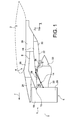
- the manufacture of the rib is started by the realization of a rib preform 46a, by superplastic forming, also called SPF (English “Superplastic Forming”).
- This preform 46a has a geometry similar to that of the final ribs 46.
- the preform 46a has an outline 50 in the overall shape of a quadrilateral, and more precisely in the form of a trapezium.
- it has a central opening 52 completely through the preform 46a, also trapezoidal overall shape, so that the preform 46a adopts a general shape of a frame following the outline of a trapezium.
- the rib preform 46a is made in one piece from a titanium alloy TAV6, which has characteristics that are suitable for carrying out the superplastic forming step enabling it to be obtained, in a manner known to the man of the job.
- One of the peculiarities of the present invention lies in the fact that the five ribs of the group are all obtained from this same rib preform 46a, which requires only a single superplastic forming tool.
- this preform 46a is greater than the size of the desired rib, even if it can be used as such for the realization of the rib of the largest group, namely that located furthest forward.
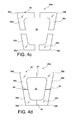
- the manufacture is continued by reducing the dimensions of the preform 46a, both according to the height and the width.
- it is proceeded to cutting said rib preform 46a, so as to split into four parts of ribs 56a to 56d.
- This division of the four parts 56a to 56d which each integrate one of the angles 58a to 58d of the trapezium, is thus made to remove material from the preform, to achieve the desired dimensions.
- the four shaded parts 60 correspond to the material withdrawals that are made, for example by machining or stamping. They are preferably each centered on their associated trapezium sides that they cross to the opening 52, even if it could be otherwise, without departing from the scope of the invention.
- the extent of the parts 60 to be deleted is all the more important that the size reduction of the preform to be made is high.
- the extent of the two parts 60 located on the sides of the trapezoid is identical, just as the extent is identical for the two parts 60 located on the bases of the trapezium.
- the figure 4c shows the four parts 56a to 56d obtained after the removal of material on the rib preform, these independent parts of each other being then placed on a conventional positioning tool (not shown), in order to make them occupy their final relative positions to obtain the desired rib.
- This also ensures precise dimensions in the two directions of the rib plane, namely in the direction of the height along which are separated the two bases of the trapezium, and in the direction of the width along which are separated the two sides of this same trapeze.
- the four preform parts 56a to 56d have been repositioned relative to each other, they are assembled by bolting, laser welding, or any other technique deemed appropriate by the skilled in the art, so as to obtain the rib Inner transverse reinforcement of reduced size.
- the recomposed rib has a contour 50 which is always substantially trapezoidal shape, without unevenness at the junctions between these parts.
- the extent of the parts 60 removed at the trapezoid bases is correlated to the extent parts 60 removed at the sides of the trapezium.
- the extent of the parts 60 to be deleted is all the more important that the size reduction of the preform to be made is high.
Landscapes
- Engineering & Computer Science (AREA)
- Aviation & Aerospace Engineering (AREA)
- Chemical & Material Sciences (AREA)
- Combustion & Propulsion (AREA)
- Mechanical Engineering (AREA)
- Structures Of Non-Positive Displacement Pumps (AREA)
- Pressure Welding/Diffusion-Bonding (AREA)
- Body Structure For Vehicles (AREA)
Applications Claiming Priority (1)
| Application Number | Priority Date | Filing Date | Title |
|---|---|---|---|
| FR1054064A FR2960522B1 (fr) | 2010-05-27 | 2010-05-27 | Procede de fabrication par formage superplastique et par eclissage d'une nervure pour carenage aerodynamique de mat d'accrochage de moteur d'aeronef |
Publications (3)
| Publication Number | Publication Date |
|---|---|
| EP2390187A2 true EP2390187A2 (de) | 2011-11-30 |
| EP2390187A3 EP2390187A3 (de) | 2013-10-16 |
| EP2390187B1 EP2390187B1 (de) | 2016-10-12 |
Family
ID=43446864
Family Applications (1)
| Application Number | Title | Priority Date | Filing Date |
|---|---|---|---|
| EP11167670.6A Active EP2390187B1 (de) | 2010-05-27 | 2011-05-26 | Herstellungsverfahren für eine Rippe einer aerodynamischen Verkleidung eines Triebwerkspylons durch superplastische Verformung und Verlaschung |
Country Status (4)
| Country | Link |
|---|---|
| US (1) | US8607453B2 (de) |
| EP (1) | EP2390187B1 (de) |
| CN (1) | CN102295076B (de) |
| FR (1) | FR2960522B1 (de) |
Cited By (5)
| Publication number | Priority date | Publication date | Assignee | Title |
|---|---|---|---|---|
| FR3021029A1 (fr) * | 2014-05-16 | 2015-11-20 | Airbus Operations Sas | Carenage aerodynamique |
| CN105109664A (zh) * | 2015-09-04 | 2015-12-02 | 西北工业大学 | 一种电机驱动的飞机外挂点密封机构 |
| US20150344140A1 (en) * | 2013-11-25 | 2015-12-03 | Airbus Operations (Sas) | Aerodynamic fairing |
| FR3069527A1 (fr) * | 2017-07-31 | 2019-02-01 | Airbus | Structure primaire a conception amelioree pour mat d'accrochage de moteur d'aeronef |
| FR3139117A1 (fr) * | 2022-08-30 | 2024-03-01 | Airbus Operations | Carenage ameliore de mât d’aeronef, ensemble de carenage, mât d’aeronef et aeronef. |
Families Citing this family (9)
| Publication number | Priority date | Publication date | Assignee | Title |
|---|---|---|---|---|
| FR2977567B1 (fr) | 2011-07-07 | 2014-12-26 | Airbus Operations Sas | Procede de refroidissement d'un plancher de protection thermique d'un carenage aerodynamique arriere d'un mat d'accrochage d'un ensemble propulsif d'aeronef |
| CN102582845A (zh) * | 2012-01-05 | 2012-07-18 | 中国商用飞机有限责任公司 | 一种飞机翼身整流罩的制作方法 |
| FR2988688B1 (fr) * | 2012-03-27 | 2014-05-09 | Airbus Operations Sas | Carenage aerodynamique arriere a tenue en temperature amelioree pour mat d'accrochage d'ensemble propulsif d'aeronef |
| CN102825428B (zh) * | 2012-08-19 | 2015-02-04 | 什邡市明日宇航工业股份有限公司 | 飞行器整流罩及其制造方法 |
| CN105392700B (zh) | 2013-07-26 | 2018-12-18 | Mra系统有限责任公司 | 飞行器发动机吊架 |
| FR3013679B1 (fr) * | 2013-11-25 | 2015-11-27 | Airbus Operations Sas | Carenage aerodynamique divise en sous-parties |
| FR3020798B1 (fr) * | 2014-05-09 | 2017-12-22 | Airbus Operations Sas | Ensemble propulsif pour aeronef comprenant un conduit formant barriere thermique integre au caisson de la structure rigide du mat d'accrochage |
| CN104708286B (zh) * | 2015-03-27 | 2017-08-25 | 沈阳飞机工业(集团)有限公司 | 飞机蒙皮与筋、框之间或飞机蒙皮与蒙皮之间的连接方法 |
| GB2578447A (en) * | 2018-10-26 | 2020-05-13 | Airbus Operations Ltd | Aircraft assembly with a hot-air exhaust outlet |
Citations (1)
| Publication number | Priority date | Publication date | Assignee | Title |
|---|---|---|---|---|
| WO2009037267A1 (fr) | 2007-09-20 | 2009-03-26 | Airbus France | Carenage aerodynamique arriere inferieur pour dispositif d'accrochage d'un moteur d'aeronef |
Family Cites Families (8)
| Publication number | Priority date | Publication date | Assignee | Title |
|---|---|---|---|---|
| US4304821A (en) * | 1978-04-18 | 1981-12-08 | Mcdonnell Douglas Corporation | Method of fabricating metallic sandwich structure |
| US5692881A (en) * | 1995-06-08 | 1997-12-02 | United Technologies Corporation | Hollow metallic structure and method of manufacture |
| US6126110A (en) * | 1997-12-22 | 2000-10-03 | Mcdonnell Douglas Corporation | Horizontally opposed trunnion forward engine mount system supported beneath a wing pylon |
| US6983912B2 (en) * | 2002-04-30 | 2006-01-10 | The Boeing Company | Hybrid exhaust heat shield for pylon mounted gas turbine engines |
| US7850058B2 (en) | 2004-03-31 | 2010-12-14 | The Boeing Company | Superplastic forming of titanium assemblies |
| FR2891252B1 (fr) * | 2005-09-28 | 2007-10-26 | Airbus France Sas | Mat a ossature monolithique |
| FR2891803B1 (fr) * | 2005-10-07 | 2007-11-30 | Airbus France Sas | Structure rigide pour mat d'accrochage de moteur d'aeronef, et mat comportant une telle structure |
| FR2913665B1 (fr) | 2007-03-16 | 2009-06-05 | Airbus France Sa | Carenage aerodynamique arriere inferieur pour dispositif d'accrochage d'un moteur d'aeronef |
-
2010
- 2010-05-27 FR FR1054064A patent/FR2960522B1/fr not_active Expired - Fee Related
-
2011
- 2011-05-25 US US13/115,408 patent/US8607453B2/en active Active
- 2011-05-26 CN CN201110150355.5A patent/CN102295076B/zh active Active
- 2011-05-26 EP EP11167670.6A patent/EP2390187B1/de active Active
Patent Citations (1)
| Publication number | Priority date | Publication date | Assignee | Title |
|---|---|---|---|---|
| WO2009037267A1 (fr) | 2007-09-20 | 2009-03-26 | Airbus France | Carenage aerodynamique arriere inferieur pour dispositif d'accrochage d'un moteur d'aeronef |
Cited By (9)
| Publication number | Priority date | Publication date | Assignee | Title |
|---|---|---|---|---|
| US20150344140A1 (en) * | 2013-11-25 | 2015-12-03 | Airbus Operations (Sas) | Aerodynamic fairing |
| US9688412B2 (en) * | 2013-11-25 | 2017-06-27 | Airbus Operations (Sas) | Aerodynamic fairing |
| FR3021029A1 (fr) * | 2014-05-16 | 2015-11-20 | Airbus Operations Sas | Carenage aerodynamique |
| US9604727B2 (en) | 2014-05-16 | 2017-03-28 | Airbus Operations (S.A.S.) | Aerodynamic fairing |
| CN105109664A (zh) * | 2015-09-04 | 2015-12-02 | 西北工业大学 | 一种电机驱动的飞机外挂点密封机构 |
| FR3069527A1 (fr) * | 2017-07-31 | 2019-02-01 | Airbus | Structure primaire a conception amelioree pour mat d'accrochage de moteur d'aeronef |
| FR3139117A1 (fr) * | 2022-08-30 | 2024-03-01 | Airbus Operations | Carenage ameliore de mât d’aeronef, ensemble de carenage, mât d’aeronef et aeronef. |
| EP4331974A1 (de) * | 2022-08-30 | 2024-03-06 | Airbus Operations | Verbesserte verkleidung für einen flugzeugpylon, verkleidungsanordnung, flugzeugpylon und flugzeug |
| US12337977B2 (en) | 2022-08-30 | 2025-06-24 | Airbus Operations Sas | Aircraft pylon fairing, fairing assembly, aircraft pylon and aircraft |
Also Published As
| Publication number | Publication date |
|---|---|
| US8607453B2 (en) | 2013-12-17 |
| US20110290936A1 (en) | 2011-12-01 |
| EP2390187A3 (de) | 2013-10-16 |
| FR2960522A1 (fr) | 2011-12-02 |
| CN102295076B (zh) | 2016-01-20 |
| EP2390187B1 (de) | 2016-10-12 |
| CN102295076A (zh) | 2011-12-28 |
| FR2960522B1 (fr) | 2012-06-29 |
Similar Documents
| Publication | Publication Date | Title |
|---|---|---|
| EP2390187B1 (de) | Herstellungsverfahren für eine Rippe einer aerodynamischen Verkleidung eines Triebwerkspylons durch superplastische Verformung und Verlaschung | |
| EP2390186B1 (de) | Herstellungsverfahren für eine Rippe zur aerodynamischen Verkleidung eines Triebwerkspylons mittels superplastischer Formung und Verlaschung | |
| EP2426051B1 (de) | Strahlturbinenpylon mit fluchtenden vorderen Befestigungspunkten | |
| EP2190739B1 (de) | Untere hinterseitige aerodynamische verkleidung für eine flugzeugmotorbefestigungsvorrichtung | |
| EP2583900B1 (de) | Aerodynamische Heckverkleidung für eine Triebwerksaufhängung, welche ein Hitzeschild umfasst, das sich frei ausdehnen kann | |
| EP1928736B1 (de) | Motoranordnung für ein luftfharzeug mit einem motor sowie einer vorrichtung zur aufhängung dieses motors | |
| EP2139769B1 (de) | Befestigung für pylonkasten an flügeln, festklemmen einer seitenplatte des kastens | |
| EP2436601B1 (de) | Vorrichtung zur Aufnahme der Schubkräfte eines Triebwerks mit drei in Reihe angeordneten Kugelgelenken | |
| EP1883578B1 (de) | Triebwerkanordnung für Flugzeuge | |
| CA2576095C (fr) | Ensemble moteur pour aeronef | |
| CA2576100C (fr) | Mat d'accrochage de turboreacteur pour aeronef | |
| EP1910167B1 (de) | Anordnung für ein flugzeug mit einem flügelsystemelement und einem befestigungsmast | |
| EP2554478B1 (de) | Schwenkbare Verkleidung für Triebwerksvekleidungen getragen von diesen Triebwerksvekleidungen im geschlossenen Zustand | |
| EP2146898A1 (de) | Hintere, untere aerodynamische verkleidung für die befestigungsvorrichtung eines flugzeugmotors | |
| EP2352673B1 (de) | Gegen eine seitenverlängerung des flugzeugrumpfes zur fixierung gepresste starre maststruktur | |
| FR3015433A1 (fr) | Ensemble pour aeronef comprenant un mat d'accrochage integre a la nacelle et agence en partie arriere du fuselage | |
| FR2965548A1 (fr) | Mat d'accrochage d'un moteur d'aeronef comprenant deux attaches voilure avant a pions de cisaillement orthogonaux | |
| FR3032421A1 (fr) | Ensemble pour aeronef comprenant une structure primaire de mat d'accrochage integree a la structure de l'element de voilure | |
| FR3020343A1 (fr) | Ensemble pour aeronef comprenant une structure primaire de mat d'accrochage constituee par trois elements independants | |
| EP1773659B1 (de) | Flugzeugmotoranordnung | |
| EP1928738B1 (de) | Motormontagestruktur zwischen einem flugzeugflügelsystem und dem motor | |
| FR3069848A1 (fr) | Structure primaire allegee pour mat d'accrochage de moteur d'aeronef | |
| FR2956706A1 (fr) | Bague d'assemblage de pieces, de preference pour attache de mat d'accrochage de turbomachine d'aeronef | |
| FR2909973A1 (fr) | Mat d'accrochage de turboreacteur pour aeronef a structure arriere de largeur transversale reduite |
Legal Events
| Date | Code | Title | Description |
|---|---|---|---|
| AK | Designated contracting states |
Kind code of ref document: A2 Designated state(s): AL AT BE BG CH CY CZ DE DK EE ES FI FR GB GR HR HU IE IS IT LI LT LU LV MC MK MT NL NO PL PT RO RS SE SI SK SM TR |
|
| AX | Request for extension of the european patent |
Extension state: BA ME |
|
| PUAI | Public reference made under article 153(3) epc to a published international application that has entered the european phase |
Free format text: ORIGINAL CODE: 0009012 |
|
| PUAL | Search report despatched |
Free format text: ORIGINAL CODE: 0009013 |
|
| AK | Designated contracting states |
Kind code of ref document: A3 Designated state(s): AL AT BE BG CH CY CZ DE DK EE ES FI FR GB GR HR HU IE IS IT LI LT LU LV MC MK MT NL NO PL PT RO RS SE SI SK SM TR |
|
| AX | Request for extension of the european patent |
Extension state: BA ME |
|
| RIC1 | Information provided on ipc code assigned before grant |
Ipc: B64F 5/00 20060101AFI20130906BHEP Ipc: B64D 33/04 20060101ALI20130906BHEP Ipc: B64D 29/06 20060101ALI20130906BHEP |
|
| 17P | Request for examination filed |
Effective date: 20131116 |
|
| RBV | Designated contracting states (corrected) |
Designated state(s): AL AT BE BG CH CY CZ DE DK EE ES FI FR GB GR HR HU IE IS IT LI LT LU LV MC MK MT NL NO PL PT RO RS SE SI SK SM TR |
|
| GRAP | Despatch of communication of intention to grant a patent |
Free format text: ORIGINAL CODE: EPIDOSNIGR1 |
|
| INTG | Intention to grant announced |
Effective date: 20160503 |
|
| GRAS | Grant fee paid |
Free format text: ORIGINAL CODE: EPIDOSNIGR3 |
|
| GRAA | (expected) grant |
Free format text: ORIGINAL CODE: 0009210 |
|
| AK | Designated contracting states |
Kind code of ref document: B1 Designated state(s): AL AT BE BG CH CY CZ DE DK EE ES FI FR GB GR HR HU IE IS IT LI LT LU LV MC MK MT NL NO PL PT RO RS SE SI SK SM TR |
|
| REG | Reference to a national code |
Ref country code: GB Ref legal event code: FG4D Free format text: NOT ENGLISH |
|
| REG | Reference to a national code |
Ref country code: CH Ref legal event code: EP |
|
| REG | Reference to a national code |
Ref country code: AT Ref legal event code: REF Ref document number: 836247 Country of ref document: AT Kind code of ref document: T Effective date: 20161015 |
|
| REG | Reference to a national code |
Ref country code: IE Ref legal event code: FG4D Free format text: LANGUAGE OF EP DOCUMENT: FRENCH |
|
| REG | Reference to a national code |
Ref country code: DE Ref legal event code: R096 Ref document number: 602011031127 Country of ref document: DE |
|
| REG | Reference to a national code |
Ref country code: LT Ref legal event code: MG4D |
|
| REG | Reference to a national code |
Ref country code: NL Ref legal event code: MP Effective date: 20161012 |
|
| PG25 | Lapsed in a contracting state [announced via postgrant information from national office to epo] |
Ref country code: LV Free format text: LAPSE BECAUSE OF FAILURE TO SUBMIT A TRANSLATION OF THE DESCRIPTION OR TO PAY THE FEE WITHIN THE PRESCRIBED TIME-LIMIT Effective date: 20161012 |
|
| REG | Reference to a national code |
Ref country code: AT Ref legal event code: MK05 Ref document number: 836247 Country of ref document: AT Kind code of ref document: T Effective date: 20161012 |
|
| PG25 | Lapsed in a contracting state [announced via postgrant information from national office to epo] |
Ref country code: SE Free format text: LAPSE BECAUSE OF FAILURE TO SUBMIT A TRANSLATION OF THE DESCRIPTION OR TO PAY THE FEE WITHIN THE PRESCRIBED TIME-LIMIT Effective date: 20161012 Ref country code: GR Free format text: LAPSE BECAUSE OF FAILURE TO SUBMIT A TRANSLATION OF THE DESCRIPTION OR TO PAY THE FEE WITHIN THE PRESCRIBED TIME-LIMIT Effective date: 20170113 Ref country code: NO Free format text: LAPSE BECAUSE OF FAILURE TO SUBMIT A TRANSLATION OF THE DESCRIPTION OR TO PAY THE FEE WITHIN THE PRESCRIBED TIME-LIMIT Effective date: 20170112 Ref country code: LT Free format text: LAPSE BECAUSE OF FAILURE TO SUBMIT A TRANSLATION OF THE DESCRIPTION OR TO PAY THE FEE WITHIN THE PRESCRIBED TIME-LIMIT Effective date: 20161012 |
|
| REG | Reference to a national code |
Ref country code: FR Ref legal event code: PLFP Year of fee payment: 7 |
|
| PG25 | Lapsed in a contracting state [announced via postgrant information from national office to epo] |
Ref country code: FI Free format text: LAPSE BECAUSE OF FAILURE TO SUBMIT A TRANSLATION OF THE DESCRIPTION OR TO PAY THE FEE WITHIN THE PRESCRIBED TIME-LIMIT Effective date: 20161012 Ref country code: PL Free format text: LAPSE BECAUSE OF FAILURE TO SUBMIT A TRANSLATION OF THE DESCRIPTION OR TO PAY THE FEE WITHIN THE PRESCRIBED TIME-LIMIT Effective date: 20161012 Ref country code: NL Free format text: LAPSE BECAUSE OF FAILURE TO SUBMIT A TRANSLATION OF THE DESCRIPTION OR TO PAY THE FEE WITHIN THE PRESCRIBED TIME-LIMIT Effective date: 20161012 Ref country code: RS Free format text: LAPSE BECAUSE OF FAILURE TO SUBMIT A TRANSLATION OF THE DESCRIPTION OR TO PAY THE FEE WITHIN THE PRESCRIBED TIME-LIMIT Effective date: 20161012 Ref country code: HR Free format text: LAPSE BECAUSE OF FAILURE TO SUBMIT A TRANSLATION OF THE DESCRIPTION OR TO PAY THE FEE WITHIN THE PRESCRIBED TIME-LIMIT Effective date: 20161012 Ref country code: PT Free format text: LAPSE BECAUSE OF FAILURE TO SUBMIT A TRANSLATION OF THE DESCRIPTION OR TO PAY THE FEE WITHIN THE PRESCRIBED TIME-LIMIT Effective date: 20170213 Ref country code: ES Free format text: LAPSE BECAUSE OF FAILURE TO SUBMIT A TRANSLATION OF THE DESCRIPTION OR TO PAY THE FEE WITHIN THE PRESCRIBED TIME-LIMIT Effective date: 20161012 Ref country code: IS Free format text: LAPSE BECAUSE OF FAILURE TO SUBMIT A TRANSLATION OF THE DESCRIPTION OR TO PAY THE FEE WITHIN THE PRESCRIBED TIME-LIMIT Effective date: 20170212 Ref country code: AT Free format text: LAPSE BECAUSE OF FAILURE TO SUBMIT A TRANSLATION OF THE DESCRIPTION OR TO PAY THE FEE WITHIN THE PRESCRIBED TIME-LIMIT Effective date: 20161012 |
|
| REG | Reference to a national code |
Ref country code: DE Ref legal event code: R097 Ref document number: 602011031127 Country of ref document: DE |
|
| PG25 | Lapsed in a contracting state [announced via postgrant information from national office to epo] |
Ref country code: SK Free format text: LAPSE BECAUSE OF FAILURE TO SUBMIT A TRANSLATION OF THE DESCRIPTION OR TO PAY THE FEE WITHIN THE PRESCRIBED TIME-LIMIT Effective date: 20161012 Ref country code: CZ Free format text: LAPSE BECAUSE OF FAILURE TO SUBMIT A TRANSLATION OF THE DESCRIPTION OR TO PAY THE FEE WITHIN THE PRESCRIBED TIME-LIMIT Effective date: 20161012 Ref country code: RO Free format text: LAPSE BECAUSE OF FAILURE TO SUBMIT A TRANSLATION OF THE DESCRIPTION OR TO PAY THE FEE WITHIN THE PRESCRIBED TIME-LIMIT Effective date: 20161012 Ref country code: EE Free format text: LAPSE BECAUSE OF FAILURE TO SUBMIT A TRANSLATION OF THE DESCRIPTION OR TO PAY THE FEE WITHIN THE PRESCRIBED TIME-LIMIT Effective date: 20161012 Ref country code: DK Free format text: LAPSE BECAUSE OF FAILURE TO SUBMIT A TRANSLATION OF THE DESCRIPTION OR TO PAY THE FEE WITHIN THE PRESCRIBED TIME-LIMIT Effective date: 20161012 |
|
| PLBE | No opposition filed within time limit |
Free format text: ORIGINAL CODE: 0009261 |
|
| STAA | Information on the status of an ep patent application or granted ep patent |
Free format text: STATUS: NO OPPOSITION FILED WITHIN TIME LIMIT |
|
| PG25 | Lapsed in a contracting state [announced via postgrant information from national office to epo] |
Ref country code: BG Free format text: LAPSE BECAUSE OF FAILURE TO SUBMIT A TRANSLATION OF THE DESCRIPTION OR TO PAY THE FEE WITHIN THE PRESCRIBED TIME-LIMIT Effective date: 20170112 Ref country code: SM Free format text: LAPSE BECAUSE OF FAILURE TO SUBMIT A TRANSLATION OF THE DESCRIPTION OR TO PAY THE FEE WITHIN THE PRESCRIBED TIME-LIMIT Effective date: 20161012 Ref country code: IT Free format text: LAPSE BECAUSE OF FAILURE TO SUBMIT A TRANSLATION OF THE DESCRIPTION OR TO PAY THE FEE WITHIN THE PRESCRIBED TIME-LIMIT Effective date: 20161012 Ref country code: LU Free format text: LAPSE BECAUSE OF NON-PAYMENT OF DUE FEES Effective date: 20170531 |
|
| 26N | No opposition filed |
Effective date: 20170713 |
|
| PG25 | Lapsed in a contracting state [announced via postgrant information from national office to epo] |
Ref country code: SI Free format text: LAPSE BECAUSE OF FAILURE TO SUBMIT A TRANSLATION OF THE DESCRIPTION OR TO PAY THE FEE WITHIN THE PRESCRIBED TIME-LIMIT Effective date: 20161012 |
|
| REG | Reference to a national code |
Ref country code: CH Ref legal event code: PL |
|
| PG25 | Lapsed in a contracting state [announced via postgrant information from national office to epo] |
Ref country code: MC Free format text: LAPSE BECAUSE OF FAILURE TO SUBMIT A TRANSLATION OF THE DESCRIPTION OR TO PAY THE FEE WITHIN THE PRESCRIBED TIME-LIMIT Effective date: 20161012 |
|
| REG | Reference to a national code |
Ref country code: IE Ref legal event code: MM4A |
|
| PG25 | Lapsed in a contracting state [announced via postgrant information from national office to epo] |
Ref country code: CH Free format text: LAPSE BECAUSE OF NON-PAYMENT OF DUE FEES Effective date: 20170531 Ref country code: LI Free format text: LAPSE BECAUSE OF NON-PAYMENT OF DUE FEES Effective date: 20170531 |
|
| PG25 | Lapsed in a contracting state [announced via postgrant information from national office to epo] |
Ref country code: LU Free format text: LAPSE BECAUSE OF NON-PAYMENT OF DUE FEES Effective date: 20170526 |
|
| REG | Reference to a national code |
Ref country code: BE Ref legal event code: MM Effective date: 20170531 |
|
| PG25 | Lapsed in a contracting state [announced via postgrant information from national office to epo] |
Ref country code: IE Free format text: LAPSE BECAUSE OF NON-PAYMENT OF DUE FEES Effective date: 20170526 |
|
| REG | Reference to a national code |
Ref country code: FR Ref legal event code: PLFP Year of fee payment: 8 |
|
| PG25 | Lapsed in a contracting state [announced via postgrant information from national office to epo] |
Ref country code: BE Free format text: LAPSE BECAUSE OF NON-PAYMENT OF DUE FEES Effective date: 20170531 |
|
| PG25 | Lapsed in a contracting state [announced via postgrant information from national office to epo] |
Ref country code: MT Free format text: LAPSE BECAUSE OF FAILURE TO SUBMIT A TRANSLATION OF THE DESCRIPTION OR TO PAY THE FEE WITHIN THE PRESCRIBED TIME-LIMIT Effective date: 20161012 |
|
| PG25 | Lapsed in a contracting state [announced via postgrant information from national office to epo] |
Ref country code: HU Free format text: LAPSE BECAUSE OF FAILURE TO SUBMIT A TRANSLATION OF THE DESCRIPTION OR TO PAY THE FEE WITHIN THE PRESCRIBED TIME-LIMIT; INVALID AB INITIO Effective date: 20110526 |
|
| PG25 | Lapsed in a contracting state [announced via postgrant information from national office to epo] |
Ref country code: CY Free format text: LAPSE BECAUSE OF NON-PAYMENT OF DUE FEES Effective date: 20161012 |
|
| PG25 | Lapsed in a contracting state [announced via postgrant information from national office to epo] |
Ref country code: MK Free format text: LAPSE BECAUSE OF FAILURE TO SUBMIT A TRANSLATION OF THE DESCRIPTION OR TO PAY THE FEE WITHIN THE PRESCRIBED TIME-LIMIT Effective date: 20161012 |
|
| PG25 | Lapsed in a contracting state [announced via postgrant information from national office to epo] |
Ref country code: TR Free format text: LAPSE BECAUSE OF FAILURE TO SUBMIT A TRANSLATION OF THE DESCRIPTION OR TO PAY THE FEE WITHIN THE PRESCRIBED TIME-LIMIT Effective date: 20161012 |
|
| PG25 | Lapsed in a contracting state [announced via postgrant information from national office to epo] |
Ref country code: AL Free format text: LAPSE BECAUSE OF FAILURE TO SUBMIT A TRANSLATION OF THE DESCRIPTION OR TO PAY THE FEE WITHIN THE PRESCRIBED TIME-LIMIT Effective date: 20161012 |
|
| PGFP | Annual fee paid to national office [announced via postgrant information from national office to epo] |
Ref country code: DE Payment date: 20250521 Year of fee payment: 15 |
|
| PGFP | Annual fee paid to national office [announced via postgrant information from national office to epo] |
Ref country code: GB Payment date: 20250521 Year of fee payment: 15 |
|
| PGFP | Annual fee paid to national office [announced via postgrant information from national office to epo] |
Ref country code: FR Payment date: 20250528 Year of fee payment: 15 |