EP2390109A1 - Method and apparatus for imprinting a three-dimensional design into a synthetic material - Google Patents
Method and apparatus for imprinting a three-dimensional design into a synthetic material Download PDFInfo
- Publication number
- EP2390109A1 EP2390109A1 EP10164340A EP10164340A EP2390109A1 EP 2390109 A1 EP2390109 A1 EP 2390109A1 EP 10164340 A EP10164340 A EP 10164340A EP 10164340 A EP10164340 A EP 10164340A EP 2390109 A1 EP2390109 A1 EP 2390109A1
- Authority
- EP
- European Patent Office
- Prior art keywords
- design
- synthetic material
- tool
- laser
- textured surface
- Prior art date
- Legal status (The legal status is an assumption and is not a legal conclusion. Google has not performed a legal analysis and makes no representation as to the accuracy of the status listed.)
- Granted
Links
- 238000013461 design Methods 0.000 title claims abstract description 155
- 229920002994 synthetic fiber Polymers 0.000 title claims abstract description 109
- 238000000034 method Methods 0.000 title claims abstract description 40
- 239000011800 void material Substances 0.000 claims abstract description 81
- 239000000463 material Substances 0.000 claims abstract description 37
- 230000008016 vaporization Effects 0.000 claims abstract description 6
- 239000010985 leather Substances 0.000 claims description 23
- 229920003023 plastic Polymers 0.000 claims description 22
- 239000004033 plastic Substances 0.000 claims description 22
- 238000010438 heat treatment Methods 0.000 claims description 8
- 238000000608 laser ablation Methods 0.000 claims description 8
- 238000002679 ablation Methods 0.000 claims description 7
- 229920000642 polymer Polymers 0.000 claims description 7
- 230000008018 melting Effects 0.000 claims description 5
- 238000002844 melting Methods 0.000 claims description 5
- 239000002356 single layer Substances 0.000 claims description 3
- 238000004519 manufacturing process Methods 0.000 claims 6
- 239000002649 leather substitute Substances 0.000 description 73
- 239000010410 layer Substances 0.000 description 30
- 238000004049 embossing Methods 0.000 description 7
- 239000000835 fiber Substances 0.000 description 4
- 239000004744 fabric Substances 0.000 description 3
- 229920000915 polyvinyl chloride Polymers 0.000 description 3
- 239000004800 polyvinyl chloride Substances 0.000 description 3
- CURLTUGMZLYLDI-UHFFFAOYSA-N Carbon dioxide Chemical compound O=C=O CURLTUGMZLYLDI-UHFFFAOYSA-N 0.000 description 2
- JNDMLEXHDPKVFC-UHFFFAOYSA-N aluminum;oxygen(2-);yttrium(3+) Chemical compound [O-2].[O-2].[O-2].[Al+3].[Y+3] JNDMLEXHDPKVFC-UHFFFAOYSA-N 0.000 description 2
- 238000004891 communication Methods 0.000 description 2
- 229910052751 metal Inorganic materials 0.000 description 2
- 239000002184 metal Substances 0.000 description 2
- 239000000203 mixture Substances 0.000 description 2
- 229910019901 yttrium aluminum garnet Inorganic materials 0.000 description 2
- 241000270728 Alligator Species 0.000 description 1
- 229910001369 Brass Inorganic materials 0.000 description 1
- 229920000742 Cotton Polymers 0.000 description 1
- 241001465754 Metazoa Species 0.000 description 1
- 229910000831 Steel Inorganic materials 0.000 description 1
- 239000004809 Teflon Substances 0.000 description 1
- 229920006362 Teflon® Polymers 0.000 description 1
- 229910052782 aluminium Inorganic materials 0.000 description 1
- XAGFODPZIPBFFR-UHFFFAOYSA-N aluminium Chemical compound [Al] XAGFODPZIPBFFR-UHFFFAOYSA-N 0.000 description 1
- 239000012237 artificial material Substances 0.000 description 1
- 239000010951 brass Substances 0.000 description 1
- 230000005587 bubbling Effects 0.000 description 1
- 229910002092 carbon dioxide Inorganic materials 0.000 description 1
- 239000001569 carbon dioxide Substances 0.000 description 1
- 230000001413 cellular effect Effects 0.000 description 1
- 239000002131 composite material Substances 0.000 description 1
- 230000001419 dependent effect Effects 0.000 description 1
- 238000006073 displacement reaction Methods 0.000 description 1
- 238000005516 engineering process Methods 0.000 description 1
- 238000001704 evaporation Methods 0.000 description 1
- 238000003780 insertion Methods 0.000 description 1
- 230000037431 insertion Effects 0.000 description 1
- 230000003278 mimic effect Effects 0.000 description 1
- 238000012986 modification Methods 0.000 description 1
- 230000004048 modification Effects 0.000 description 1
- 229920000728 polyester Polymers 0.000 description 1
- 229910001220 stainless steel Inorganic materials 0.000 description 1
- 239000010935 stainless steel Substances 0.000 description 1
- 239000010959 steel Substances 0.000 description 1
- 239000000126 substance Substances 0.000 description 1
- 239000012209 synthetic fiber Substances 0.000 description 1
- 238000011282 treatment Methods 0.000 description 1
Images



Classifications
-
- B—PERFORMING OPERATIONS; TRANSPORTING
- B44—DECORATIVE ARTS
- B44F—SPECIAL DESIGNS OR PICTURES
- B44F9/00—Designs imitating natural patterns
- B44F9/12—Designs imitating natural patterns of leather
-
- B—PERFORMING OPERATIONS; TRANSPORTING
- B44—DECORATIVE ARTS
- B44C—PRODUCING DECORATIVE EFFECTS; MOSAICS; TARSIA WORK; PAPERHANGING
- B44C1/00—Processes, not specifically provided for elsewhere, for producing decorative surface effects
- B44C1/22—Removing surface-material, e.g. by engraving, by etching
- B44C1/228—Removing surface-material, e.g. by engraving, by etching by laser radiation
-
- B—PERFORMING OPERATIONS; TRANSPORTING
- B44—DECORATIVE ARTS
- B44C—PRODUCING DECORATIVE EFFECTS; MOSAICS; TARSIA WORK; PAPERHANGING
- B44C1/00—Processes, not specifically provided for elsewhere, for producing decorative surface effects
- B44C1/24—Pressing or stamping ornamental designs on surfaces
Definitions
- the present disclosure relates generally to methods of imprinting synthetic material. More specifically, the present disclosure relates to imprinting a three-dimensional design into a textured surface of a synthetic material.
- Synthetic material such as artificial or synthetic leather, appears to have a genuine finish, but the actual material is a material with a composite layer or a blend of materials that gives the appearance of the genuine leather. Synthetic material can also be considered artificial material, or faux material. These synthetic materials can simulate different types of leather or different natural materials,
- synthetic leather is made of other materials or a blend of polymers that receives numerous treatments so that the resulting material replicates the look of real or genuine leather and some of the common attributes of genuine leather.
- Synthetic leather is typically made from plastics. Some synthetic leather can be made solely of materials such as polyvinyl chloride (1'VC). Other types of synthetic leather can include cloth material, such as polyester or cotton that is coated with substances to replicate the look of leather.
- one type of synthetic leather called leatherette is made by covering a fabric base with plastics. In leatherette, the fabric can be made of a natural or synthetic fiber which is then covered with a soft PVC layer.
- FIG. 1 is a front view of an exemplary electronic device
- FIG. 2 is an example of sheet of synthetic leather having a distorted design resulting from a traditional heated imprinting or branding or branding method typically used on genuine leather;
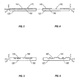
- FIG. 3 is a cross-section view of synthetic material having a textured surface characterized by peaks and valleys;
- FIG. 4 is an illustration of the synthetic material depicted in FIG. 3 after a portion of the synthetic material has been laser-ablated;
- FIG. 5 is a cross-section view of synthetic material in accordance with an alternative implementation of the present disclosure, before a portion of the synthetic material has been laser-ablated;
- FIG. 6 is an illustration of the layer depicted in FIG. 5 after a portion of the synthetic material has been laser-ablated;
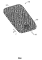
- FIG. 7 is a perspective view of an exemplary layer of synthetic material covering the back of an electronic device and having a design laser-ablated onto the synthetic material;
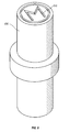
- FIG. 8 is a perspective view of an exemplary tool for imprinting a design on a synthetic material after a portion of the material has been laser-ablated;
- FIG. 9 is a perspective view of the layer of synthetic material illustrated in FIG. 7 after a portion of the synthetic material has been imprinted by the tool depicted in FIG. 8 ;
- FIG. 10 a close-up view of the design depicted in FIG. 9 ;
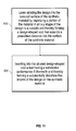
- FIG. 11 is a flow chart of the method of imprinting a three-dimensional design into a synthetic material, in accordance with an exemplary implementation of the present disclosure.
- the word “synthetic” can also mean artificial, faux, fake, imitation, or the like.
- synthetic leather can include pleather, artificial leather, leatherette, polymer sheets having a leather appearance, Koskin, poromeric imitation leather, a polymer of uniform synthetic material having a textured layer resembling leather, or the like.
- ablation is defined as vaporizing, sublimating, or evaporating a material very quickly using a laser while not permitting the material to liquefy or melt.
- imprinting includes embossing, debossing, impressing, stamping, branding, or any other method of forming a textured, raised, or substantially three-dimensional design or image, into, out of, or onto the surface of a material.
- textured surface is defined as a surface characterized by peaks and valleys, including uniformly shaped and spaced peaks and valleys and non-uniformly shaped and spaced peaks and valleys.
- the phrase "textured surface” can also include a surface characterized by hills and dips, plateaus and basins, steps and recesses, or any other shapes, so that the surface has a feel other than smooth.
- peaks are portions of a surface that are at a higher height or elevation than at least two adjacent portions or points. It is also contemplated that “valleys” are portions of a surface that are at a lower elevation or depth than at least two adjacent portions or points. In other words, “peaks” and “valleys” refer to a surface having high points and portions, as well as a low points and portions.
- the phrase “strike zone” refers to the area of a surface or material where an ablation laser will strike or ablate the material.
- skin refers to a top layer, a layering, a single layer of material, a covering, or a sheet of material that covers a surface of an object.
- this disclosure will focus on synthetic leather.
- synthetic, artificial, or faux materials such as faux suede, are considered within the scope of this disclosure.
- the method of imprinting synthetic leather can be applied to any object that has a layer of synthetic leather, as synthetic leather is used on a wide variety of products.
- synthetic leather can be used for clothing, shoes, computer laptop cases, CD wallets, book covers, wallets, and the like.
- synthetic leather can be used as a skin for the back cover of mobile devices, such as a cellular phone, a personal digital assistant (PDA), a portable MP3 player, or a smartphone, or a handheld communication device 100, such as the one illustrated in FIG. 1 .
- mobile devices such as a cellular phone, a personal digital assistant (PDA), a portable MP3 player, or a smartphone, or a handheld communication device 100, such as the one illustrated in FIG. 1 .
- the skin 120 has been imprinted with a design 130 using a heated embossing method.
- the skin 120 is made of synthetic leather.
- the design 130 is misshapen, distorted, and comprises a build-up 135 of melted plastic at the bottom of the design 130.
- embossing the skin 120 of the back cover resulted in displacement of some of the synthetic leather
- the design 130 is distorted due to the plastic in the synthetic leather.
- heating the plastic in the synthetic leather can melt the plastic so much that the resulting material no longer looks like genuine leather nor has the texture of genuine leather.
- genuine leather is a stable material, the heat from the branding or embossing does not melt the leather as can happen with synthetic leather.
- the tool is heated to a temperature that is sufficient to induce plastic deformation in the synthetic material when the tool contact engages the material for a prescribed period of stamp-time.
- the method can include positioning a sheet of synthetic material having a textured surface in the strike zone of an ablating laser.
- the method can include ablating the strike zone to extend a design-shaped void into the textured surface of the synthetic material at least as deep as the valleys to be crossed by the void.
- FIGS. 3-4 are illustrations of the cross-section of a layer 120 of synthetic material covering a back cover of an electronic device 100, where the cross-section is taken along the horizontal x-direction axis of the electronic device.
- the synthetic material illustrated in FIGS. 3-4 is synthetic leather.
- the layer 120 is characterized by a plurality of peaks 140 and valleys 150 that are evenly and uniformly shaped and spaced.
- the peaks 140 and valleys 150 can also be unevenly and non-uniformly shaped and spaced and can be any other shape or pattern that provides a textured surface for the synthetic material.
- the peaks 140 and valleys 150 give the synthetic leather a leather-like appearance.
- different patterns of peaks 140 and valleys 150 can be arranged so as to represent different types of leather.
- the illustrated example has a saw-tooth like appearance
- the peaks 140 and valleys 150 as contemplated herein can include multiple types of peaks 140 and valley 150.
- the peaks 140 can be flat, pointed, sloped, or other configurations.
- the valleys 150 can have similar shapes.
- the width of each peak 140 or valley 150 can vary as well.
- dimples i.e., valleys
- the peaks can be broad plateaus, and the valleys can be narrow.
- FIG. 3 is an illustration of a layer 120 of synthetic leather before a portion of the synthetic leather has been laser-ablated.
- FIG. 4 is an illustration the layer 120 of synthetic leather depicted in FIG. 3 after a portion of the synthetic leather has been laser-ablated.
- the strike-zone portion 170 of the synthetic leather is the portion to be laser-ablated when placed under the strike zone of the ablating laser.
- the ablating laser can be a fiber laser, a carbon dioxide laser, yttrium-aluminum-garnet (YAG) laser, or other similar laser.
- the design-shaped void 185 extends into the textured surface 120 at least as deep as the valleys 150 crossed by the void 185.
- the layer 120 is ablated just to the point of the depth of the valleys 150 to expose the subsurface of the synthetic material.
- FIGS. 3-4 illustrate valleys 150 that have the same depth, one of ordinary skill in the art will appreciate that the valleys 150 can vary in depth.
- the design-shaped void 185 would be laser-ablated to extend into the textured surface at least as deep as the valley that will cross the design-shaped void 185, and that valley may not necessarily be the deepest valley of the synthetic material. In the particular example illustrated in FIG.
- the ablating laser vaporizes the layer 120 to expose the subsurface of the synthetic material and to smooth the bottom of the design-shaped void 185. While the depth illustrated in FIGS. 3-4 is the depth of the valley, it is contemplated that in designs having valleys of various depths, it is not necessary to extend the void 185 to the depth of deepest valley, but rather extending the void 185 to an intermediary valley or the valley(s) which the design-shaped void 185 crosses is appropriate.
- a three-dimensional design 180 can be laser-ablated into the strike-zone portion 170 of a layer 120 of synthetic leather, as illustrated in FIGS. 5-6.
- FIG. 5 illustrates another example of a cross-section of a layer 120 of synthetic leather before the strike-zone portion 170 of the synthetic leather has been laser-ablated, where the cross-section is taken along an x-direction axis of the layer 120.
- FIG. 6 illustrates the layer 120 of synthetic material after the strike-zone portion 170 of the synthetic leather has been laser-ablated to have a design 180 formed in the synthetic leather.
- a design 180 is laser-ablated into the textured surface of the synthetic leather by laser-ablating an x-y shape of the design 180 to a predetermined z-depth, thereby resulting in a three-dimensional design 180 outlined by a design-shaped void 185 that extends a prescribed distance into the textured surface of the layer 120 of synthetic leather.
- the ablating laser traces a design-shaped void 185 that outlines the shape of a design 180 on the strike zone portion 170 so that the design 180 is three-dimensional and appears to protrude in an upwards z-direction away from the design-shaped void 185.
- the ablating laser ablates the design 180 into the surface of the synthetic material and vaporizes areas of the strike-zone portion 170 in an x-y shape of the design 180 to a predetermined z-depth to provide the design-shaped void 185 that gives the design 180 a three-dimensional appearance. For example, in FIG.
- the design-shape void 185 outlines the design 180, and the design 180 protrudes upward in the z-direction away from the design-shaped void 185, thereby creating a three-dimensional design.
- the resulting design 180 has the appearance of a three-dimensional design 180 but may have soft or not-well-defined edges, as will be discussed with reference to FIG. 7 .
- the shape and depth of the laser-ablated design 180 and the design-shaped void 185 depend on the texture of the synthetic material which can affect the strength and power of the ablating laser, the number of passes that the laser takes across the strike-zone portion of the synthetic material, and the time the laser is exposed to the surface of the synthetic material.
- the strength of the laser be enough to bring the synthetic material past the material's melting point to vaporize the synthetic material but not so proximate to the melting point that the synthetic material begins to melt; otherwise bubbling of the material may occur and distort or damage the design 180.
- the power of the ablating laser should be enough to instantaneously vaporize the design 180 into the synthetic material so that material surrounding the design 180 is not heated.
- the ablating laser should be exposed to the surface for a time that permits the synthetic material to vaporize but not so long that the material begins to melt and distort the design 180.
- the power, time, and pressure parameters are unique to each synthetic material and the depth of the cut required to ablate below the textured surface.
- FIG. 7 is an illustration of the back cover of an electronic device 100 having a layer 120 of synthetic leather.
- a design 180 has been laser-ablated towards the bottom of the back cover of the electronic device 100.
- the design 180 illustrated in FIG. 7 is an M-shape encompassed by a circular ring, it will be appreciated that the design 180 can have any shape, simple or ornate, so long as the shape can be defined by an x-y directional pattern and have a z-directional depth.
- the spaces between the M-shape and the ring of the design 180 are the design-shaped void 185.
- the layer 120 of synthetic leather has been laser-ablated in an x-y shape to vaporize the portions of the synthetic leather to form the design-shaped void 185 that extends a prescribed distance into the synthetic leather and outlines the design 180.
- the design 180 is the non-vaporized (in other words, the non-ablated) portions of the synthetic leather which provides the three-dimensional portion of the design 180.
- the resulting M-shape and ring encompassing the M-shape have softened and not-well-defined edges.
- a tool can be inserted into the design-shaped void 185.
- FIG. 8 is an illustration of an exemplary tool 600 that can be inserted into the ablated design-shaped void 185 of the synthetic leather depicted in FIG. 7 .
- the tool 600 is an imprinting tool.
- a stamp 610 that corresponds to the design 180 that is ablated on the synthetic leather.
- the stamp 610 is an M-shape encompassed by a ring.
- the recesses of the stamp 610 correspond to the three-dimensional portions of the design 180 that protrude away from the design-shaped void 185.
- the tool 600 has a substantial conformance fit with the design 180 and the design-shaped void 185.
- the tool 600 can be a hand tool whereby an individual manually inserts the tool 600 into the design-shaped void 185 of the synthetic leather.
- the tool 600 can be a component of an imprinting apparatus that mechanically inserts the tool 600 into the design-shaped void 185.
- the imprinting apparatus can be a Teflon sleeve or bushing through which the tool 600 is guided for insertion into the design-shaped void 185.
- the tool 600 is made of aluminum.
- the tool 600 can be made of steel, stainless steel, brass, or any other metal can be heated and maintained at a high temperature.
- the tool 600 can be made of a metal that is robust so that the tool 600 can be repeatedly used to imprint a three-dimensional design on synthetic materials with minimal damage to the tool 600.
- a tool 600 such as illustrated in FIG. 8 is inserted into the design-shaped void 185 of the synthetic leather.
- the tool 600 has a stamp 610 having a substantial conformance fit with the design 180 and the design-shaped void 185 of the laser-ablated synthetic leather, the edges and shape of the design 180 is more defined than the just the laser-ablated design.
- a substantially distortion-free imprint of the design 180 is formed on the synthetic leather.
- the tool 600 illustrated in FIG. 8 is by way of example, and other tools or apparatuses that have a substantial conformance fit with the design-shaped void 185 made by laser ablation is considered within the disclosure.
- FIG. 9 An example of a design 180 that has been laser-ablated and then stamped using the exemplary tool 600 shown in FIG. 8 is illustrated in FIG. 9 .
- the resulting M-shape design 180 and the ring encompassing the M-shape is more defined than the laser-ablated design 180 illustrated in FIG. 7 .
- the tool 600 is heated to a temperature sufficient to induce plastic deformation in the synthetic material when contact-engaged by the tool 600 for a prescribed period of stamp-time.
- the tool 600 can be heated to a 232 degrees Celsius before the tool 600 is inserted into the design-shaped void 185 of the laser-ablated layer 120 of synthetic leather.
- the tool 600 can be heated to a temperature sufficient to induce plastic deformation of the synthetic leather but less than the melting the synthetic leather.
- the heated tool 600 allows for the three-dimensional and protruding portions of the laser-ablated design 180 to conform to the stamp 600, thereby resulting in a more defined and distortion-free design 180 imprinted on the synthetic leather.
- the tool 600 can be inserted into the design-shaped void 185 for a prescribed period of stamp-time to ensuring that the laser-ablated design 180 substantially conforms to the stamp 610 of the tool 600, thereby resulting in a defined distortion-free imprint of the design 180 on the synthetic leather.
- the stamp-time can extend less than five seconds.
- the stamp-time can be one second, half a second, ten seconds, or any other stamp-time that will result in a defined distortion-free imprint of the design 180 when the tool 600 is removed from the design-shaped void 185 of the synthetic leather.
- the tool 600 contacts the design-shaped void 185 momentarily or for a brief stamp-time that is sufficient to ensure that when the tool 600 is removed the resulting design 180 is substantially distortion-free.
- the tool 600 when the tool 600 is inserted into the design-shaped void 185, the tool 600 is inserted with pressure.
- the tool 600 be inserted into the design-shaped void 185 at a suitable pressure that is enough to leave a distortion-free imprint of the design 180 on the synthetic material but not so much that the stamp 610 of the tool passes through and cuts through the synthetic material.
- the tool 500 contacts the design-shaped void 185 with at least a minimum pressure that is sufficient to ensure that when the tool 600 is removed the resulting design 180 is substantially distortian-free.
- a layer 120 of synthetic leather is first laser-ablated with a design 180 having an x-y shape and z-depth and outlined by a design-shaped void 185. Then, a tool 600, which can be heated, is inserted into the design-shaped void 185 of the laser-ablated design 180 with an applied pressure for a period of stamp-time and is then removed from the void 185 to leave a substantially distortion-free design 180 on the synthetic leather.
- the laser-ablation changes the surface of the synthetic material to form the three-dimensional design 180 into the synthetic material, and the stamping by the tool 600 allows for definition and smoother edges of the design 180.
- FIG. 10 is a close-up view of the laser-ablated-then-stamped design 180 imprinted on the strike-zone portion 170 of the layer 120 of synthetic leather illustrated in FIG. 9 .
- the top surface of the design 180 has the textured surface of the synthetic leather, and the design-shaped void 185 is at least partially smoothed out as a result of the laser-ablating.
- the design 180 is an x-y shape that protrudes upward from the design-shaped void 185 to give the design 180 a z-depth that has sharp defined edges. Comparing the laser-ablated-then-stamped design 180 illustrated in FIG. 10 and the traditionally heat-imprinted design 130 illustrated in FIG.
- the laser-ablated-then-stamped design 180 in FIG. 10 is substantially distortion-free.
- the design 180 in FIG. 10 does not have melted plastic build-ups 135 that are found in the design 130 in FIG. 2 .
- the melted plastic build-ups 135 that can be found on synthetic leather imprinted using methods typically performed on genuine leather are reduced and can be eliminated by first laser-ablating the design and then imprinting or stamping the design as discussed hereinabove.
- the resulting design 180 of the method of the present disclosure is a more defined three-dimensional design that has an appearance of branded, stamped, or imprinted genuine leather.
- the ablating laser is a fiber laser and the depth of a valley in the strike-zone portion 170 of a layer 120 of synthetic leather is approximately 0.2 millimeters.
- the fiber laser having a 20 Watt power rating can be set to a power of approximately 30% of 20 Watts.
- the type of design, depth or design, and depth of the textured surface of the synthetic material affects the type of ablating laser needed to ablate the synthetic material.
- the type of ablating laser used will depend on the depth of the textured surface of the synthetic material and the type of design to be imprinted on the synthetic material, as the laser will need to have a suitable power to ablate the textured surface to the desired depth.
- the power of a particular laser can be varied to accommodate a plurality of designs and materials.
- the type of laser may need to be changed in addition to the power setting to accommodate the design material.
- lasers of a general type emit a laser beam of a given wavelength, and power settings can be controlled; but, the cutting depth can be limited by the type of laser. As described herein, the selection of laser and power is dependent upon at least one of design and depth.
- the method of imprinting a three-dimensional design on a synthetic material includes laser-ablating a design onto the synthetic material to vaporize the voids of the design and then imprinting the laser-ablated design by inserting a tool into the voids of the laser-ablated design, thereby forming a defined and substantially distortion-free imprint of the design on the synthetic material.
- the laser-ablation of the design and the imprinting of the design are performed in conjunction to form the substantially distortion-free three-dimensional design on the synthetic leather.
- FIG. 11 is a flow chart of an exemplary method of imprinting a three-dimensional design into a textured surface of a synthetic material.
- the method includes laser-ablating the design 180 into the textured surface 120 of the synthetic material by vaporizing a portion 170 of the material in an x-y shape of the design 180 to a predetermined z-depth and thereby forming a design-shaped void 185 that extends a prescribed distance into the textured surface 120 of the synthetic material.
- the method includes laser-ablating the design 180 into the textured surface 120 of the synthetic material by vaporizing a portion 170 of the material in an x-y shape of the design 180 to a predetermined z-depth and thereby forming a design-shaped void 185 that extends a prescribed distance into the textured surface 120 of the synthetic material.
- a three-dimensional design imprinted synthetic material can be manufactured so that the a distortion-free impression of a three-dimensional design that is substantially without z-dimension displaced material adjacent to the x-y dimension boundaries of the design at the textured surface by laser-ablating and inserting an imprinting tool as described herein.
Landscapes
- Physics & Mathematics (AREA)
- Health & Medical Sciences (AREA)
- General Health & Medical Sciences (AREA)
- Optics & Photonics (AREA)
- Toxicology (AREA)
- Synthetic Leather, Interior Materials Or Flexible Sheet Materials (AREA)
- Treatment And Processing Of Natural Fur Or Leather (AREA)
- Laser Beam Processing (AREA)
Abstract
Description
- The present disclosure relates generally to methods of imprinting synthetic material. More specifically, the present disclosure relates to imprinting a three-dimensional design into a textured surface of a synthetic material.
- Synthetic material, such as artificial or synthetic leather, appears to have a genuine finish, but the actual material is a material with a composite layer or a blend of materials that gives the appearance of the genuine leather. Synthetic material can also be considered artificial material, or faux material. These synthetic materials can simulate different types of leather or different natural materials,
- Instead of being made of animal skin, synthetic leather is made of other materials or a blend of polymers that receives numerous treatments so that the resulting material replicates the look of real or genuine leather and some of the common attributes of genuine leather. Synthetic leather is typically made from plastics. Some synthetic leather can be made solely of materials such as polyvinyl chloride (1'VC). Other types of synthetic leather can include cloth material, such as polyester or cotton that is coated with substances to replicate the look of leather. For example, one type of synthetic leather called leatherette is made by covering a fabric base with plastics. In leatherette, the fabric can be made of a natural or synthetic fiber which is then covered with a soft PVC layer.
- Implementations of the present disclosure will now be described, by way of example only, with reference to the attached Figures, wherein:
-
FIG. 1 is a front view of an exemplary electronic device; -
FIG. 2 is an example of sheet of synthetic leather having a distorted design resulting from a traditional heated imprinting or branding or branding method typically used on genuine leather; -
FIG. 3 is a cross-section view of synthetic material having a textured surface characterized by peaks and valleys; -
FIG. 4 is an illustration of the synthetic material depicted inFIG. 3 after a portion of the synthetic material has been laser-ablated; -
FIG. 5 is a cross-section view of synthetic material in accordance with an alternative implementation of the present disclosure, before a portion of the synthetic material has been laser-ablated; -
FIG. 6 is an illustration of the layer depicted inFIG. 5 after a portion of the synthetic material has been laser-ablated; -
FIG. 7 is a perspective view of an exemplary layer of synthetic material covering the back of an electronic device and having a design laser-ablated onto the synthetic material; -
FIG. 8 is a perspective view of an exemplary tool for imprinting a design on a synthetic material after a portion of the material has been laser-ablated; -
FIG. 9 is a perspective view of the layer of synthetic material illustrated inFIG. 7 after a portion of the synthetic material has been imprinted by the tool depicted inFIG. 8 ; and -
FIG. 10 a close-up view of the design depicted inFIG. 9 ; and -
FIG. 11 is a flow chart of the method of imprinting a three-dimensional design into a synthetic material, in accordance with an exemplary implementation of the present disclosure. - It will be appreciated that for simplicity and clarity of illustration, where appropriate, reference numerals have been repeated among the different figures to indicate corresponding or analogous elements. In addition, numerous specific details are set forth in order to provide a thorough understanding of the implementations described herein. However, it will be understood by those of ordinary skill in the art that the implementations described herein can be practiced without these specific details. In other instances, methods, procedures and components have not been described in detail so as not to obscure the related relevant feature being described. Also, the description is not to be considered as limiting the scope of the implementations described herein.
- Several definitions that apply throughout this document will now be presented. The word "synthetic" can also mean artificial, faux, fake, imitation, or the like. The term "synthetic leather" can include pleather, artificial leather, leatherette, polymer sheets having a leather appearance, Koskin, poromeric imitation leather, a polymer of uniform synthetic material having a textured layer resembling leather, or the like. The terms "ablation," "ablate," or "ablating" are defined as vaporizing, sublimating, or evaporating a material very quickly using a laser while not permitting the material to liquefy or melt. The term "imprinting" includes embossing, debossing, impressing, stamping, branding, or any other method of forming a textured, raised, or substantially three-dimensional design or image, into, out of, or onto the surface of a material. The term "textured surface" is defined as a surface characterized by peaks and valleys, including uniformly shaped and spaced peaks and valleys and non-uniformly shaped and spaced peaks and valleys. The phrase "textured surface" can also include a surface characterized by hills and dips, plateaus and basins, steps and recesses, or any other shapes, so that the surface has a feel other than smooth. It is contemplated that "peaks" are portions of a surface that are at a higher height or elevation than at least two adjacent portions or points. It is also contemplated that "valleys" are portions of a surface that are at a lower elevation or depth than at least two adjacent portions or points. In other words, "peaks" and "valleys" refer to a surface having high points and portions, as well as a low points and portions. The phrase "strike zone" refers to the area of a surface or material where an ablation laser will strike or ablate the material. The term "skin" refers to a top layer, a layering, a single layer of material, a covering, or a sheet of material that covers a surface of an object.
- For purposes of brevity and as an example, this disclosure will focus on synthetic leather. However, one of ordinary skill in the art will appreciate that other synthetic, artificial, or faux materials, such as faux suede, are considered within the scope of this disclosure. Additionally, while the following disclosure discusses a method of imprinting the synthetic leather covering a back cover a handheld mobile device, one of ordinary skill in the art will appreciate that the method of imprinting synthetic leather can be applied to any object that has a layer of synthetic leather, as synthetic leather is used on a wide variety of products. For example, synthetic leather can be used for clothing, shoes, computer laptop cases, CD wallets, book covers, wallets, and the like. In one example, synthetic leather can be used as a skin for the back cover of mobile devices, such as a cellular phone, a personal digital assistant (PDA), a portable MP3 player, or a smartphone, or a
handheld communication device 100, such as the one illustrated inFIG. 1 . - As synthetic leather is designed to mimic real or genuine leather, there is a demand that synthetic leather include designs, embossing, imprints, and brands that can be found on real or genuine leather products. However, because synthetic leather is typically made of plastic, the traditional methods of embossing, imprinting, and branding natural or real leather cannot be used on synthetic leather. For example, branding and embossing often requires simply placing a combination of heat and pressure directly on the material. If heat and pressure are placed on synthetic leather which contains plastic, the heat causes the plastic to melt which can distort the design to be branded, embossed, or imprinted on the synthetic leather. For example,
FIG. 2 is an illustration of askin 120 for the back cover of thehandheld communication device 100 illustrated inFIG. 1 , wherein theskin 120 has been imprinted with adesign 130 using a heated embossing method. Theskin 120 is made of synthetic leather. As seen inFIG. 2 , thedesign 130 is misshapen, distorted, and comprises a build-up 135 of melted plastic at the bottom of thedesign 130. InFIG. 2 , while embossing theskin 120 of the back cover resulted in displacement of some of the synthetic leather, thedesign 130 is distorted due to the plastic in the synthetic leather. Additionally, heating the plastic in the synthetic leather can melt the plastic so much that the resulting material no longer looks like genuine leather nor has the texture of genuine leather. As genuine leather is a stable material, the heat from the branding or embossing does not melt the leather as can happen with synthetic leather. Thus, there is difficulty in imitating branded designs, imprinted designs, and embossed designs typically found in genuine leather products in synthetic leather products. - Thus, a method for imprinting a three-dimensional design into a textured surface of a synthetic material is disclosed herein. The method can include laser-ablating a design into the textured surface of a synthetic material by vaporizing a portion of the material in an x-y shape of the design to a predetermined z-depth, thereby forming a design-shaped void that extends a prescribed distance into the textured surface of the synthetic material. The method also includes inserting a tool having a substantial conformance fit with the design-shaped void into the ablated design-shaped void, thereby forming a substantially distortion-free imprint of the design on the synthetic material. In at least one implementation, the tool is heated to a temperature that is sufficient to induce plastic deformation in the synthetic material when the tool contact engages the material for a prescribed period of stamp-time. In another implementation, the method can include positioning a sheet of synthetic material having a textured surface in the strike zone of an ablating laser. In yet another implementation, the method can include ablating the strike zone to extend a design-shaped void into the textured surface of the synthetic material at least as deep as the valleys to be crossed by the void.
- The method and apparatus for imprinting a three-dimensional design into a textured surface of a synthetic material will be described with reference to
FIGS. 3-10 . Additionally, as presented herein, a product resulting from the process is described as well.FIGS. 3-4 are illustrations of the cross-section of alayer 120 of synthetic material covering a back cover of anelectronic device 100, where the cross-section is taken along the horizontal x-direction axis of the electronic device. The synthetic material illustrated inFIGS. 3-4 is synthetic leather. As illustrated inFIGS. 3-4 , thelayer 120 is characterized by a plurality ofpeaks 140 andvalleys 150 that are evenly and uniformly shaped and spaced. However, one of ordinary skill in the art will appreciate that thepeaks 140 andvalleys 150 can also be unevenly and non-uniformly shaped and spaced and can be any other shape or pattern that provides a textured surface for the synthetic material. Thepeaks 140 andvalleys 150 give the synthetic leather a leather-like appearance. Additionally, it is contemplated that different patterns ofpeaks 140 andvalleys 150 can be arranged so as to represent different types of leather. While the illustrated example has a saw-tooth like appearance, thepeaks 140 andvalleys 150 as contemplated herein can include multiple types ofpeaks 140 andvalley 150. For example, thepeaks 140 can be flat, pointed, sloped, or other configurations. Likewise, thevalleys 150 can have similar shapes. The width of each peak 140 orvalley 150 can vary as well. To simulate cowhide leather, dimples (i.e., valleys) can be dispersed. To simulate alligator leather, the peaks can be broad plateaus, and the valleys can be narrow. -
FIG. 3 is an illustration of alayer 120 of synthetic leather before a portion of the synthetic leather has been laser-ablated.FIG. 4 is an illustration thelayer 120 of synthetic leather depicted inFIG. 3 after a portion of the synthetic leather has been laser-ablated. InFIG. 3 , the strike-zone portion 170 of the synthetic leather is the portion to be laser-ablated when placed under the strike zone of the ablating laser. When the ablating laser contacts the strike-zone portion 170, surfaces of the strike-zone portion 170 are vaporized to form a design-shapedvoid 185 that will result in a design on the synthetic material. The ablating laser can be a fiber laser, a carbon dioxide laser, yttrium-aluminum-garnet (YAG) laser, or other similar laser. - As shown in
FIG. 4 , the design-shapedvoid 185 extends into thetextured surface 120 at least as deep as thevalleys 150 crossed by thevoid 185. In other words, thelayer 120 is ablated just to the point of the depth of thevalleys 150 to expose the subsurface of the synthetic material. WhileFIGS. 3-4 illustratevalleys 150 that have the same depth, one of ordinary skill in the art will appreciate that thevalleys 150 can vary in depth. Thus, the design-shapedvoid 185 would be laser-ablated to extend into the textured surface at least as deep as the valley that will cross the design-shapedvoid 185, and that valley may not necessarily be the deepest valley of the synthetic material. In the particular example illustrated inFIG. 4 , the ablating laser vaporizes thelayer 120 to expose the subsurface of the synthetic material and to smooth the bottom of the design-shapedvoid 185. While the depth illustrated inFIGS. 3-4 is the depth of the valley, it is contemplated that in designs having valleys of various depths, it is not necessary to extend the void 185 to the depth of deepest valley, but rather extending the void 185 to an intermediary valley or the valley(s) which the design-shapedvoid 185 crosses is appropriate. - In at least one implementation, a three-
dimensional design 180 can be laser-ablated into the strike-zone portion 170 of alayer 120 of synthetic leather, as illustrated inFIGS. 5-6. FIG. 5 illustrates another example of a cross-section of alayer 120 of synthetic leather before the strike-zone portion 170 of the synthetic leather has been laser-ablated, where the cross-section is taken along an x-direction axis of thelayer 120.FIG. 6 illustrates thelayer 120 of synthetic material after the strike-zone portion 170 of the synthetic leather has been laser-ablated to have adesign 180 formed in the synthetic leather. InFIG. 6 , adesign 180 is laser-ablated into the textured surface of the synthetic leather by laser-ablating an x-y shape of thedesign 180 to a predetermined z-depth, thereby resulting in a three-dimensional design 180 outlined by a design-shapedvoid 185 that extends a prescribed distance into the textured surface of thelayer 120 of synthetic leather. - In at least one alternative implementation, the ablating laser traces a design-shaped
void 185 that outlines the shape of adesign 180 on thestrike zone portion 170 so that thedesign 180 is three-dimensional and appears to protrude in an upwards z-direction away from the design-shapedvoid 185. In other words, the ablating laser ablates thedesign 180 into the surface of the synthetic material and vaporizes areas of the strike-zone portion 170 in an x-y shape of thedesign 180 to a predetermined z-depth to provide the design-shapedvoid 185 that gives the design 180 a three-dimensional appearance. For example, inFIG. 6 , the design-shape void 185 outlines thedesign 180, and thedesign 180 protrudes upward in the z-direction away from the design-shapedvoid 185, thereby creating a three-dimensional design. In this implementation, after thelayer 120 has been laser-ablated, the resultingdesign 180 has the appearance of a three-dimensional design 180 but may have soft or not-well-defined edges, as will be discussed with reference toFIG. 7 . The shape and depth of the laser-ablateddesign 180 and the design-shapedvoid 185 depend on the texture of the synthetic material which can affect the strength and power of the ablating laser, the number of passes that the laser takes across the strike-zone portion of the synthetic material, and the time the laser is exposed to the surface of the synthetic material. One of ordinary skill in the art would appreciate that the strength of the laser be enough to bring the synthetic material past the material's melting point to vaporize the synthetic material but not so proximate to the melting point that the synthetic material begins to melt; otherwise bubbling of the material may occur and distort or damage thedesign 180. Essentially, the power of the ablating laser should be enough to instantaneously vaporize thedesign 180 into the synthetic material so that material surrounding thedesign 180 is not heated. However, one of ordinary skill in the art would understand that the ablating laser should be exposed to the surface for a time that permits the synthetic material to vaporize but not so long that the material begins to melt and distort thedesign 180. In other words, the power, time, and pressure parameters are unique to each synthetic material and the depth of the cut required to ablate below the textured surface. -
FIG. 7 is an illustration of the back cover of anelectronic device 100 having alayer 120 of synthetic leather. As shown inFIG. 7 , adesign 180 has been laser-ablated towards the bottom of the back cover of theelectronic device 100. While thedesign 180 illustrated inFIG. 7 is an M-shape encompassed by a circular ring, it will be appreciated that thedesign 180 can have any shape, simple or ornate, so long as the shape can be defined by an x-y directional pattern and have a z-directional depth. The spaces between the M-shape and the ring of thedesign 180 are the design-shapedvoid 185. InFIG. 7 , thelayer 120 of synthetic leather has been laser-ablated in an x-y shape to vaporize the portions of the synthetic leather to form the design-shapedvoid 185 that extends a prescribed distance into the synthetic leather and outlines thedesign 180. Thedesign 180 is the non-vaporized (in other words, the non-ablated) portions of the synthetic leather which provides the three-dimensional portion of thedesign 180. As illustrated inFIG. 7 , the resulting M-shape and ring encompassing the M-shape have softened and not-well-defined edges. To further define the edges and shape of thedesign 180, a tool can be inserted into the design-shapedvoid 185. -
FIG. 8 is an illustration of anexemplary tool 600 that can be inserted into the ablated design-shapedvoid 185 of the synthetic leather depicted inFIG. 7 . As seen inFIG. 8 , thetool 600 is an imprinting tool. On one end of thetool 600 is astamp 610 that corresponds to thedesign 180 that is ablated on the synthetic leather. In the particular example illustrated inFIG. 8 , thestamp 610 is an M-shape encompassed by a ring. The recesses of thestamp 610 correspond to the three-dimensional portions of thedesign 180 that protrude away from the design-shapedvoid 185. Thus, thetool 600 has a substantial conformance fit with thedesign 180 and the design-shapedvoid 185. Thetool 600 can be a hand tool whereby an individual manually inserts thetool 600 into the design-shapedvoid 185 of the synthetic leather. Alternatively, thetool 600 can be a component of an imprinting apparatus that mechanically inserts thetool 600 into the design-shapedvoid 185. For example, the imprinting apparatus can be a Teflon sleeve or bushing through which thetool 600 is guided for insertion into the design-shapedvoid 185. InFIG. 7 , thetool 600 is made of aluminum. However, one of ordinary skill will appreciate that thetool 600 can be made of steel, stainless steel, brass, or any other metal can be heated and maintained at a high temperature. Additionally, thetool 600 can be made of a metal that is robust so that thetool 600 can be repeatedly used to imprint a three-dimensional design on synthetic materials with minimal damage to thetool 600. - After a strike-
zone portion 170 of alayer 120 of synthetic leather has been laser-ablated, atool 600 such as illustrated inFIG. 8 is inserted into the design-shapedvoid 185 of the synthetic leather. As thetool 600 has astamp 610 having a substantial conformance fit with thedesign 180 and the design-shapedvoid 185 of the laser-ablated synthetic leather, the edges and shape of thedesign 180 is more defined than the just the laser-ablated design. As a result of inserting thetool 600 into the laser-shapedvoid 185 of thedesign 180 on the synthetic leather, a substantially distortion-free imprint of thedesign 180 is formed on the synthetic leather. One of ordinary skill in the art will appreciate that thetool 600 illustrated inFIG. 8 is by way of example, and other tools or apparatuses that have a substantial conformance fit with the design-shapedvoid 185 made by laser ablation is considered within the disclosure. - An example of a
design 180 that has been laser-ablated and then stamped using theexemplary tool 600 shown inFIG. 8 is illustrated inFIG. 9 . InFIG. 9 , after thetool 600 has been inserted into the design-shapedvoid 185 of the laser-ablatedlayer 120 of synthetic leather, the resulting M-shape design 180 and the ring encompassing the M-shape is more defined than the laser-ablateddesign 180 illustrated inFIG. 7 . - In at least one implementation, the
tool 600 is heated to a temperature sufficient to induce plastic deformation in the synthetic material when contact-engaged by thetool 600 for a prescribed period of stamp-time. For example, thetool 600 can be heated to a 232 degrees Celsius before thetool 600 is inserted into the design-shapedvoid 185 of the laser-ablatedlayer 120 of synthetic leather. In other implementations, thetool 600 can be heated to a temperature sufficient to induce plastic deformation of the synthetic leather but less than the melting the synthetic leather. Theheated tool 600 allows for the three-dimensional and protruding portions of the laser-ablateddesign 180 to conform to thestamp 600, thereby resulting in a more defined and distortion-free design 180 imprinted on the synthetic leather. - Additionally, the
tool 600 can be inserted into the design-shapedvoid 185 for a prescribed period of stamp-time to ensuring that the laser-ablateddesign 180 substantially conforms to thestamp 610 of thetool 600, thereby resulting in a defined distortion-free imprint of thedesign 180 on the synthetic leather. In at least one implementation, the stamp-time can extend less than five seconds. In other implementations, the stamp-time can be one second, half a second, ten seconds, or any other stamp-time that will result in a defined distortion-free imprint of thedesign 180 when thetool 600 is removed from the design-shapedvoid 185 of the synthetic leather. Thus, one of ordinary skill in the art will appreciate that thetool 600 contacts the design-shapedvoid 185 momentarily or for a brief stamp-time that is sufficient to ensure that when thetool 600 is removed the resultingdesign 180 is substantially distortion-free. - Furthermore, when the
tool 600 is inserted into the design-shapedvoid 185, thetool 600 is inserted with pressure. One of ordinary skill in the art will appreciate that thetool 600 be inserted into the design-shapedvoid 185 at a suitable pressure that is enough to leave a distortion-free imprint of thedesign 180 on the synthetic material but not so much that thestamp 610 of the tool passes through and cuts through the synthetic material. Thus, one of ordinary skill in the art will appreciate that the tool 500 contacts the design-shapedvoid 185 with at least a minimum pressure that is sufficient to ensure that when thetool 600 is removed the resultingdesign 180 is substantially distortian-free. - Thus, as described above, a
layer 120 of synthetic leather is first laser-ablated with adesign 180 having an x-y shape and z-depth and outlined by a design-shapedvoid 185. Then, atool 600, which can be heated, is inserted into the design-shapedvoid 185 of the laser-ablateddesign 180 with an applied pressure for a period of stamp-time and is then removed from the void 185 to leave a substantially distortion-free design 180 on the synthetic leather. The laser-ablation changes the surface of the synthetic material to form the three-dimensional design 180 into the synthetic material, and the stamping by thetool 600 allows for definition and smoother edges of thedesign 180.FIG. 10 is a close-up view of the laser-ablated-then-stampeddesign 180 imprinted on the strike-zone portion 170 of thelayer 120 of synthetic leather illustrated inFIG. 9 . InFIG. 10 , the top surface of thedesign 180 has the textured surface of the synthetic leather, and the design-shapedvoid 185 is at least partially smoothed out as a result of the laser-ablating. As illustrated inFIG. 10 , thedesign 180 is an x-y shape that protrudes upward from the design-shapedvoid 185 to give the design 180 a z-depth that has sharp defined edges. Comparing the laser-ablated-then-stampeddesign 180 illustrated inFIG. 10 and the traditionally heat-imprinteddesign 130 illustrated inFIG. 2 , the laser-ablated-then-stampeddesign 180 inFIG. 10 is substantially distortion-free. For example, thedesign 180 inFIG. 10 does not have melted plastic build-ups 135 that are found in thedesign 130 inFIG. 2 . The melted plastic build-ups 135 that can be found on synthetic leather imprinted using methods typically performed on genuine leather are reduced and can be eliminated by first laser-ablating the design and then imprinting or stamping the design as discussed hereinabove. Thus, the resultingdesign 180 of the method of the present disclosure is a more defined three-dimensional design that has an appearance of branded, stamped, or imprinted genuine leather. - In at least one illustrative example, the ablating laser is a fiber laser and the depth of a valley in the strike-
zone portion 170 of alayer 120 of synthetic leather is approximately 0.2 millimeters. To ablate adesign void 185 to the depth of the valley in the strike-zone portion 170, the fiber laser having a 20 Watt power rating can be set to a power of approximately 30% of 20 Watts. After laser ablating thedesign void 185 into the synthetic leather, atool 600 can be momentarily contact-engaged with thedesign void 185 with one kilogram of force for less than three seconds. - In another illustrative example, if the design is to be ablated into a strike-
zone portion 170 having a valley depth of approximately 0.4 millimeters, the ablating laser can be set to a power of approximately 60% of 20 Watts to ensure thedesign void 185 is ablated to a depth of approximately 0.4 millimeters. When thetool 600 is inserted into thedesign void 185, thetool 600 can be contact-engaged with thedesign void 185 with less than one kilogram of force for less than five seconds. - Thus, an ablating laser that is a fiber laser to be used on synthetic leather having a textured surface with a depth of approximately 0.2-0.4 millimeters can be set to between approximately 30% and 60% of 20 Watts. Additionally, the
tool 600 can be contact-engaged with the resultant ablated-design void 185 for less than five seconds under less than one kilogram of force. - As discussed above, one of ordinary skill in the art will appreciate that the type of design, depth or design, and depth of the textured surface of the synthetic material affects the type of ablating laser needed to ablate the synthetic material. For example, the type of ablating laser used will depend on the depth of the textured surface of the synthetic material and the type of design to be imprinted on the synthetic material, as the laser will need to have a suitable power to ablate the textured surface to the desired depth. In some instances, the power of a particular laser can be varied to accommodate a plurality of designs and materials. In other instances, the type of laser may need to be changed in addition to the power setting to accommodate the design material. For example, lasers of a general type emit a laser beam of a given wavelength, and power settings can be controlled; but, the cutting depth can be limited by the type of laser. As described herein, the selection of laser and power is dependent upon at least one of design and depth.
- Additionally, it will be appreciated that the
tool 600 will be inserted into theablated design void 185 such that thetool 600 contact-engages the void 185 for a moment. For example, thetool 600 can barely touch thevoid 185 with a small amount of pressure, such as less than one kilogram of force, for as few as one or two seconds. - As described in the preceding paragraphs, the method of imprinting a three-dimensional design on a synthetic material includes laser-ablating a design onto the synthetic material to vaporize the voids of the design and then imprinting the laser-ablated design by inserting a tool into the voids of the laser-ablated design, thereby forming a defined and substantially distortion-free imprint of the design on the synthetic material. The laser-ablation of the design and the imprinting of the design are performed in conjunction to form the substantially distortion-free three-dimensional design on the synthetic leather.
-
FIG. 11 is a flow chart of an exemplary method of imprinting a three-dimensional design into a textured surface of a synthetic material. Atblock 910, the method includes laser-ablating thedesign 180 into thetextured surface 120 of the synthetic material by vaporizing aportion 170 of the material in an x-y shape of thedesign 180 to a predetermined z-depth and thereby forming a design-shapedvoid 185 that extends a prescribed distance into thetextured surface 120 of the synthetic material. For example, as described above in relation toFIGS. 3-8 , the surface of a portion of the synthetic material is positioned in the strike zone of an ablating laser, and the laser ablates an x-y shape of adesign 180 into the surface to a predetermined z-depth. The laser vaporizes portions of the synthetic material to form the design-shapedvoid 185 that outlines thedesign 180 thereby providing as a three-dimensional imprint on the synthetic material. As described above, the ablating-laser is set to a particular power or strength, depending on the depth of thedesign 180 and the type of synthetic material that is to be ablated, and the ablating-laser ablates thedesign 180 onto the synthetic material. In at least one implementation, the ablating laser ablates portions of the synthetic material to a depth that is at least as deep as the valleys crossed by the design-shapedvoid 185. - At
block 920 ofFIG. 11 , after the synthetic material has been laser-ablated, the method includes inserting into the ablated design-shaped void 185 atool 600 having a substantial conformance fit therewith and thereby forming a substantially distortion-free imprint of thedesign 180 on the synthetic material. For example, atblock 920, atool 600 such as the one illustrated inFIG. 8 is inserted with an amount of pressure into the design-shapedvoid 185 formed by the ablating laser to ensure a conformance fit of thetool 600 with the design-shapedvoid 185 and the three-dimensional portions of thedesign 180. In at least one implementation, the method can also include heating thetool 600 to a temperature sufficient to induce plastic deformation in the synthetic material when contact-engaged by thetool 600 for a prescribed period of stamp-time. In another implementation, the tool can be heated to a temperature sufficient to induce permanent plastic deformation in the synthetic material. Additionally, the method can also include removing thetool 600 from the design-shapedvoid 185 thereby leaving a substantially distortion-free imprint of the design in the synthetic material. Thus, a three dimensional design imprinted synthetic material made according to the method described above can include a textured surface having an ablated-then-stamped, distortion-free impression of a three-dimensional design that is substantially without z-dimension displaced material adjacent the x-y dimension boundaries of the design at the textured surface. Additionally, a three-dimensional design imprinted synthetic material can be manufactured so that the a distortion-free impression of a three-dimensional design that is substantially without z-dimension displaced material adjacent to the x-y dimension boundaries of the design at the textured surface by laser-ablating and inserting an imprinting tool as described herein. - While the exemplary implementations have been described hereinabove regarding a method of imprinting a three-dimensional design on a synthetic leather, the method of imprinting a three-dimensional design can be implemented on other synthetic materials such as suede, sheets of polymers having a textured layer, sheets of polyvinyl chloride having a textured layer, or the like. Various modifications to and departures from the disclosed implementations will occur to those having skill in the art. The subject matter that is intended to be within the spirit of this disclosure is set forth in the following claims.
Claims (15)
- A method for imprinting a three-dimensional design (180) into a textured surface of a synthetic material (120), the method comprising:laser-ablating (910) the design (185) into the textured surface of the synthetic material (120) by vaporizing a portion of the material in an x-y shape of the design (180) to a predetermined z-depth and thereby forming a design-shaped void (185) that extends a prescribed distance into the textured surface of the synthetic material (120); andinserting (920) into the ablated design-shaped void (185) a tool (600) having a substantial conformance fit therewith and thereby forming a substantially distortion-free imprint of the design (180) on the synthetic material (120).
- The method as recited in claim 1, further comprising:heating the tool (600) to a temperature sufficient to induce plastic deformation in the synthetic material (120) when contact-engaged by the tool (600) for a prescribed period of stamp-time.
- The method as recited in any one of the preceding claims, further comprising:heating the tool (600) to a temperature sufficient to induce plastic deformation in the synthetic material (120) when contact-engaged by the tool (600) for a prescribed period of stamp-time and the temperature being less than the melting temperature of the synthetic material (120).
- The method as recited in any one of the preceding claims, further comprising:heating the tool (600) to a temperature sufficient to induce permanent plastic deformation in the synthetic material (120) when contact-engaged by the tool (600) for a prescribed period of stamp-time extending less than five seconds.
- The method as recited in any one of the preceding claims, further comprising:positioning in the strike zone (170) of an ablating laser, prior to the laser-ablation, a sheet of synthetic material (120) having a textured surface characterized by peaks (140) and valleys (150) and during the ablation, extending the design-shaped void (185) into the textured surface of the synthetic material (120) at least as deep as valleys (150) crossed by the void (185).
- The method as recited in any one of the preceding claims, further comprising:positioning in the strike zone (170) of an ablating laser, prior to the laser-ablation, a polymer sheet having a leather appearance comprising a textured surface characterized by peaks (140) and valleys (150) and during the ablation, extending the design-shaped void (185) into the textured surface of the synthetic material (120) at least as deep as valleys (150) crossed by the void (185).
- The method as recited in any one of claims 1-4, further comprising:positioning in the strike zone (170) of an ablating laser, prior to the laser-ablation, a single layer polymer sheet of substantially uniform synthetic material (120) into which the design-shaped void (185) extends after ablation.
- The method as recited in any one of the preceding claims, further comprising:applying less than one kilogram of force upon the inserted tool (600) for less than five seconds and then removing the tool (600) from the void (185).
- A three-dimensional design imprinted synthetic material (120) manufactured by the method comprising:laser-ablating (910) the design into a textured surface of the synthetic material (120) by vaporizing a portion of the material in an x-y shape of the design (180) to a predetermined z-depth and thereby forming a design-shaped void (185) that extends a prescribed distance into the textured surface of the synthetic material (120); andinserting into the ablated design-shaped void (185) a tool (600) having a substantial conformance fit therewith and thereby forming a distortion-free impression of the three-dimensional design (180) that is substantially without z-dimension displaced material adjacent x-y dimension boundaries of the design at the textured surface.
- The three-dimensional design imprinted synthetic material as recited in claim 9, wherein the manufacturing method further comprises:heating the tool (600) to a temperature sufficient to induce permanent plastic deformation in the synthetic material (120) when contact-engaged by the tool (600) for a prescribed period of stamp-time.
- The three-dimensional design imprinted synthetic material as recited in any one of claims 9-10, wherein the manufacturing method further comprises:heating the tool (600) to a temperature sufficient to induce plastic deformation in the synthetic material (120) when contact-engaged by the tool (600) for a prescribed period of stamp-time and the temperature being less than the melting temperature of the synthetic material (120).
- The three-dimensional design imprinted synthetic material as recited in any one of claims 9-11, wherein the manufacturing method further comprises:heating the tool (600) to a temperature sufficient to induce plastic deformation in the synthetic material (120) when contact-engaged by the tool (600) for a prescribed period of stamp-time extending less than five seconds.
- The three-dimensional design imprinted synthetic material as recited in any one of claims 9-12, wherein the manufacturing method further comprises:positioning in the strike zone (170) of an ablating laser, prior to the laser-ablation, a sheet of synthetic material (120) having a textured surface characterized by peaks (140) and valleys (150) and during the ablation, extending the design-shaped void (185) into the textured surface of the synthetic material (120) at least as deep as valleys (150) crossed by the void (185).
- The three-dimensional design imprinted synthetic material as recited in any one of claims 9-12, wherein the manufacturing method further comprises:positioning in the strike zone (170) of an ablating laser, prior to the laser-ablation, a single layer polymer sheet of substantially uniform synthetic material (120) into which the design-shaped void (185) extends after ablation.
- The three-dimensional design imprinted synthetic material as recited in any one of claims 9-14, wherein the manufacturing method further comprises:applying less than one kilogram of force upon the inserted tool (600) for less than five seconds and then removing the tool (600) from the void (185).
Priority Applications (2)
| Application Number | Priority Date | Filing Date | Title |
|---|---|---|---|
| EP20100164340 EP2390109B1 (en) | 2010-05-28 | 2010-05-28 | Method for imprinting a three-dimensional design into a synthetic material |
| CA 2738159 CA2738159C (en) | 2010-05-28 | 2011-04-21 | Method and apparatus for imprinting a three-dimensional design into a synthetic material |
Applications Claiming Priority (1)
| Application Number | Priority Date | Filing Date | Title |
|---|---|---|---|
| EP20100164340 EP2390109B1 (en) | 2010-05-28 | 2010-05-28 | Method for imprinting a three-dimensional design into a synthetic material |
Publications (2)
| Publication Number | Publication Date |
|---|---|
| EP2390109A1 true EP2390109A1 (en) | 2011-11-30 |
| EP2390109B1 EP2390109B1 (en) | 2013-03-06 |
Family
ID=43479444
Family Applications (1)
| Application Number | Title | Priority Date | Filing Date |
|---|---|---|---|
| EP20100164340 Not-in-force EP2390109B1 (en) | 2010-05-28 | 2010-05-28 | Method for imprinting a three-dimensional design into a synthetic material |
Country Status (2)
| Country | Link |
|---|---|
| EP (1) | EP2390109B1 (en) |
| CA (1) | CA2738159C (en) |
Cited By (1)
| Publication number | Priority date | Publication date | Assignee | Title |
|---|---|---|---|---|
| CN106297544A (en) * | 2015-05-21 | 2017-01-04 | 联想(北京)有限公司 | Electronic product and the method forming mark on electronic product |
Families Citing this family (1)
| Publication number | Priority date | Publication date | Assignee | Title |
|---|---|---|---|---|
| CN105578817A (en) * | 2016-01-29 | 2016-05-11 | 广东新秀新材料股份有限公司 | Composite Material Logo and Manufacturing Method of Electronic Product Protective Case |
Citations (3)
| Publication number | Priority date | Publication date | Assignee | Title |
|---|---|---|---|---|
| WO2000074891A1 (en) * | 1999-06-03 | 2000-12-14 | Foba-North America Laser Systems I, Llc | Method of three dimensional laser engraving |
| WO2005030430A1 (en) * | 2003-09-26 | 2005-04-07 | Peguform Gmbh | Method and device for removing material from a three-dimensional surface in a multi-layered manner by means of a laser, using a polygon network which is described by a mathematical function and represents the surface |
| DE10344292A1 (en) * | 2003-09-23 | 2005-04-21 | Reinhard Wagner | Method for applying titles to book binding uses three dimensional laser cutting and decorative inserts |
-
2010
- 2010-05-28 EP EP20100164340 patent/EP2390109B1/en not_active Not-in-force
-
2011
- 2011-04-21 CA CA 2738159 patent/CA2738159C/en not_active Expired - Fee Related
Patent Citations (3)
| Publication number | Priority date | Publication date | Assignee | Title |
|---|---|---|---|---|
| WO2000074891A1 (en) * | 1999-06-03 | 2000-12-14 | Foba-North America Laser Systems I, Llc | Method of three dimensional laser engraving |
| DE10344292A1 (en) * | 2003-09-23 | 2005-04-21 | Reinhard Wagner | Method for applying titles to book binding uses three dimensional laser cutting and decorative inserts |
| WO2005030430A1 (en) * | 2003-09-26 | 2005-04-07 | Peguform Gmbh | Method and device for removing material from a three-dimensional surface in a multi-layered manner by means of a laser, using a polygon network which is described by a mathematical function and represents the surface |
Cited By (1)
| Publication number | Priority date | Publication date | Assignee | Title |
|---|---|---|---|---|
| CN106297544A (en) * | 2015-05-21 | 2017-01-04 | 联想(北京)有限公司 | Electronic product and the method forming mark on electronic product |
Also Published As
| Publication number | Publication date |
|---|---|
| CA2738159A1 (en) | 2011-11-28 |
| CA2738159C (en) | 2014-10-21 |
| EP2390109B1 (en) | 2013-03-06 |
Similar Documents
| Publication | Publication Date | Title |
|---|---|---|
| US5834037A (en) | Apparatus for making insignias with raised designs | |
| US8181993B2 (en) | ID card comprising a contoured relief structure, and corresponding production method | |
| EP2418077A1 (en) | Resin-coated material and method for manufacturing same | |
| CN103269825A (en) | Interior component for vehicle | |
| CA2923315A1 (en) | Method for producing a surface structure on a pressing tool by applying metal coatings | |
| CA2738159C (en) | Method and apparatus for imprinting a three-dimensional design into a synthetic material | |
| JP6761135B2 (en) | Thermoplastic synthetic resin three-dimensional decorative piece and its manufacturing method | |
| US20110293887A1 (en) | Method and apparatus for imprinting a three-dimensional design into a synthetic material | |
| CN110712443A (en) | Concave-convex texture mold and manufacturing method and application thereof | |
| US20090142531A1 (en) | Method of Forming Note Pads With Shaped Sides | |
| US20110045237A1 (en) | Elimination of odor caused by laser-etching leather | |
| KR20090083577A (en) | How to make decorative paper for clothing | |
| ATE1637T1 (en) | METHOD AND APPARATUS FOR MAKING A FOAM BALL WITH EMBOSSED SURFACE. | |
| KR100777974B1 (en) | Hotfix manufacturing method that enables a deep comb pattern | |
| US20050276887A1 (en) | Method of marking smoked food products | |
| JP4806786B2 (en) | Simulated skin and method for producing the same | |
| KR101448407B1 (en) | End Pattern Restoring Method for Mended Jeans | |
| JP6210443B2 (en) | Method for manufacturing wax mold for jewelry | |
| JPS583063B2 (en) | Moyo emboss Kakohouhou | |
| KR20060039097A (en) | Manufacturing method of product labeling sphere using natural mother-of-pearl and product labeling sphere using the same | |
| JPS61195791A (en) | Carving method by laser beam | |
| US313029A (en) | Method of making ornamental and other designs in relief | |
| WO2007042825A1 (en) | A three-dimensional article | |
| RU2471704C1 (en) | Method of making leather articles (versions) | |
| RU2561904C2 (en) | Method of obtaining wide-format art drawing on front surface of natural leather using laser engraving machine |
Legal Events
| Date | Code | Title | Description |
|---|---|---|---|
| 17P | Request for examination filed |
Effective date: 20100607 |
|
| AK | Designated contracting states |
Kind code of ref document: A1 Designated state(s): AL AT BE BG CH CY CZ DE DK EE ES FI FR GB GR HR HU IE IS IT LI LT LU LV MC MK MT NL NO PL PT RO SE SI SK SM TR |
|
| AX | Request for extension of the european patent |
Extension state: BA ME RS |
|
| PUAI | Public reference made under article 153(3) epc to a published international application that has entered the european phase |
Free format text: ORIGINAL CODE: 0009012 |
|
| GRAP | Despatch of communication of intention to grant a patent |
Free format text: ORIGINAL CODE: EPIDOSNIGR1 |
|
| GRAS | Grant fee paid |
Free format text: ORIGINAL CODE: EPIDOSNIGR3 |
|
| GRAA | (expected) grant |
Free format text: ORIGINAL CODE: 0009210 |
|
| AK | Designated contracting states |
Kind code of ref document: B1 Designated state(s): AL AT BE BG CH CY CZ DE DK EE ES FI FR GB GR HR HU IE IS IT LI LT LU LV MC MK MT NL NO PL PT RO SE SI SK SM TR |
|
| REG | Reference to a national code |
Ref country code: GB Ref legal event code: FG4D |
|
| REG | Reference to a national code |
Ref country code: AT Ref legal event code: REF Ref document number: 599376 Country of ref document: AT Kind code of ref document: T Effective date: 20130315 Ref country code: CH Ref legal event code: EP |
|
| REG | Reference to a national code |
Ref country code: IE Ref legal event code: FG4D |
|
| REG | Reference to a national code |
Ref country code: DE Ref legal event code: R096 Ref document number: 602010005185 Country of ref document: DE Effective date: 20130508 |
|
| REG | Reference to a national code |
Ref country code: AT Ref legal event code: MK05 Ref document number: 599376 Country of ref document: AT Kind code of ref document: T Effective date: 20130306 |
|
| PG25 | Lapsed in a contracting state [announced via postgrant information from national office to epo] |
Ref country code: LT Free format text: LAPSE BECAUSE OF FAILURE TO SUBMIT A TRANSLATION OF THE DESCRIPTION OR TO PAY THE FEE WITHIN THE PRESCRIBED TIME-LIMIT Effective date: 20130306 Ref country code: ES Free format text: LAPSE BECAUSE OF FAILURE TO SUBMIT A TRANSLATION OF THE DESCRIPTION OR TO PAY THE FEE WITHIN THE PRESCRIBED TIME-LIMIT Effective date: 20130617 Ref country code: NO Free format text: LAPSE BECAUSE OF FAILURE TO SUBMIT A TRANSLATION OF THE DESCRIPTION OR TO PAY THE FEE WITHIN THE PRESCRIBED TIME-LIMIT Effective date: 20130606 Ref country code: SE Free format text: LAPSE BECAUSE OF FAILURE TO SUBMIT A TRANSLATION OF THE DESCRIPTION OR TO PAY THE FEE WITHIN THE PRESCRIBED TIME-LIMIT Effective date: 20130306 Ref country code: BG Free format text: LAPSE BECAUSE OF FAILURE TO SUBMIT A TRANSLATION OF THE DESCRIPTION OR TO PAY THE FEE WITHIN THE PRESCRIBED TIME-LIMIT Effective date: 20130606 Ref country code: AT Free format text: LAPSE BECAUSE OF FAILURE TO SUBMIT A TRANSLATION OF THE DESCRIPTION OR TO PAY THE FEE WITHIN THE PRESCRIBED TIME-LIMIT Effective date: 20130306 |
|
| REG | Reference to a national code |
Ref country code: NL Ref legal event code: T3 |
|
| REG | Reference to a national code |
Ref country code: CH Ref legal event code: PFA Owner name: BLACKBERRY LIMITED, CA Free format text: FORMER OWNER: RESEARCH IN MOTION LIMITED, CA |
|
| REG | Reference to a national code |
Ref country code: LT Ref legal event code: MG4D |
|
| PG25 | Lapsed in a contracting state [announced via postgrant information from national office to epo] |
Ref country code: FI Free format text: LAPSE BECAUSE OF FAILURE TO SUBMIT A TRANSLATION OF THE DESCRIPTION OR TO PAY THE FEE WITHIN THE PRESCRIBED TIME-LIMIT Effective date: 20130306 Ref country code: SI Free format text: LAPSE BECAUSE OF FAILURE TO SUBMIT A TRANSLATION OF THE DESCRIPTION OR TO PAY THE FEE WITHIN THE PRESCRIBED TIME-LIMIT Effective date: 20130306 Ref country code: LV Free format text: LAPSE BECAUSE OF FAILURE TO SUBMIT A TRANSLATION OF THE DESCRIPTION OR TO PAY THE FEE WITHIN THE PRESCRIBED TIME-LIMIT Effective date: 20130306 Ref country code: GR Free format text: LAPSE BECAUSE OF FAILURE TO SUBMIT A TRANSLATION OF THE DESCRIPTION OR TO PAY THE FEE WITHIN THE PRESCRIBED TIME-LIMIT Effective date: 20130607 |
|
| RAP2 | Party data changed (patent owner data changed or rights of a patent transferred) |
Owner name: BLACKBERRY LIMITED |
|
| PG25 | Lapsed in a contracting state [announced via postgrant information from national office to epo] |
Ref country code: BE Free format text: LAPSE BECAUSE OF FAILURE TO SUBMIT A TRANSLATION OF THE DESCRIPTION OR TO PAY THE FEE WITHIN THE PRESCRIBED TIME-LIMIT Effective date: 20130306 Ref country code: HR Free format text: LAPSE BECAUSE OF FAILURE TO SUBMIT A TRANSLATION OF THE DESCRIPTION OR TO PAY THE FEE WITHIN THE PRESCRIBED TIME-LIMIT Effective date: 20130306 |
|
| PG25 | Lapsed in a contracting state [announced via postgrant information from national office to epo] |
Ref country code: EE Free format text: LAPSE BECAUSE OF FAILURE TO SUBMIT A TRANSLATION OF THE DESCRIPTION OR TO PAY THE FEE WITHIN THE PRESCRIBED TIME-LIMIT Effective date: 20130306 Ref country code: PT Free format text: LAPSE BECAUSE OF FAILURE TO SUBMIT A TRANSLATION OF THE DESCRIPTION OR TO PAY THE FEE WITHIN THE PRESCRIBED TIME-LIMIT Effective date: 20130708 Ref country code: SK Free format text: LAPSE BECAUSE OF FAILURE TO SUBMIT A TRANSLATION OF THE DESCRIPTION OR TO PAY THE FEE WITHIN THE PRESCRIBED TIME-LIMIT Effective date: 20130306 Ref country code: RO Free format text: LAPSE BECAUSE OF FAILURE TO SUBMIT A TRANSLATION OF THE DESCRIPTION OR TO PAY THE FEE WITHIN THE PRESCRIBED TIME-LIMIT Effective date: 20130306 Ref country code: CZ Free format text: LAPSE BECAUSE OF FAILURE TO SUBMIT A TRANSLATION OF THE DESCRIPTION OR TO PAY THE FEE WITHIN THE PRESCRIBED TIME-LIMIT Effective date: 20130306 Ref country code: IS Free format text: LAPSE BECAUSE OF FAILURE TO SUBMIT A TRANSLATION OF THE DESCRIPTION OR TO PAY THE FEE WITHIN THE PRESCRIBED TIME-LIMIT Effective date: 20130706 |
|
| REG | Reference to a national code |
Ref country code: CH Ref legal event code: PCOW Free format text: NEW ADDRESS: 2200 UNIVERSITY AVENUE EAST, WATERLOO, ON N2K 0A7 (CA) |
|
| RAP2 | Party data changed (patent owner data changed or rights of a patent transferred) |
Owner name: BLACKBERRY LIMITED |
|
| PG25 | Lapsed in a contracting state [announced via postgrant information from national office to epo] |
Ref country code: PL Free format text: LAPSE BECAUSE OF FAILURE TO SUBMIT A TRANSLATION OF THE DESCRIPTION OR TO PAY THE FEE WITHIN THE PRESCRIBED TIME-LIMIT Effective date: 20130306 |
|
| PG25 | Lapsed in a contracting state [announced via postgrant information from national office to epo] |
Ref country code: MC Free format text: LAPSE BECAUSE OF FAILURE TO SUBMIT A TRANSLATION OF THE DESCRIPTION OR TO PAY THE FEE WITHIN THE PRESCRIBED TIME-LIMIT Effective date: 20130306 |
|
| PLBE | No opposition filed within time limit |
Free format text: ORIGINAL CODE: 0009261 |
|
| STAA | Information on the status of an ep patent application or granted ep patent |
Free format text: STATUS: NO OPPOSITION FILED WITHIN TIME LIMIT |
|
| PG25 | Lapsed in a contracting state [announced via postgrant information from national office to epo] |
Ref country code: DK Free format text: LAPSE BECAUSE OF FAILURE TO SUBMIT A TRANSLATION OF THE DESCRIPTION OR TO PAY THE FEE WITHIN THE PRESCRIBED TIME-LIMIT Effective date: 20130306 |
|
| 26N | No opposition filed |
Effective date: 20131209 |
|
| REG | Reference to a national code |
Ref country code: IE Ref legal event code: MM4A |
|
| PG25 | Lapsed in a contracting state [announced via postgrant information from national office to epo] |
Ref country code: IT Free format text: LAPSE BECAUSE OF FAILURE TO SUBMIT A TRANSLATION OF THE DESCRIPTION OR TO PAY THE FEE WITHIN THE PRESCRIBED TIME-LIMIT Effective date: 20130306 |
|
| REG | Reference to a national code |
Ref country code: DE Ref legal event code: R097 Ref document number: 602010005185 Country of ref document: DE Effective date: 20131209 |
|
| PG25 | Lapsed in a contracting state [announced via postgrant information from national office to epo] |
Ref country code: IE Free format text: LAPSE BECAUSE OF NON-PAYMENT OF DUE FEES Effective date: 20130528 |
|
| PGFP | Annual fee paid to national office [announced via postgrant information from national office to epo] |
Ref country code: GB Payment date: 20140527 Year of fee payment: 5 |
|
| PGFP | Annual fee paid to national office [announced via postgrant information from national office to epo] |
Ref country code: FR Payment date: 20140519 Year of fee payment: 5 Ref country code: NL Payment date: 20140526 Year of fee payment: 5 Ref country code: DE Payment date: 20140529 Year of fee payment: 5 |
|
| REG | Reference to a national code |
Ref country code: DE Ref legal event code: R082 Ref document number: 602010005185 Country of ref document: DE Representative=s name: MERH-IP MATIAS ERNY REICHL HOFFMANN, DE |
|
| REG | Reference to a national code |
Ref country code: DE Ref legal event code: R082 Ref document number: 602010005185 Country of ref document: DE Representative=s name: MERH-IP MATIAS ERNY REICHL HOFFMANN, DE Effective date: 20140926 Ref country code: DE Ref legal event code: R081 Ref document number: 602010005185 Country of ref document: DE Owner name: BLACKBERRY LIMITED, WATERLOO, CA Free format text: FORMER OWNER: RESEARCH IN MOTION LIMITED, WATERLOO, ONTARIO, CA Effective date: 20140926 Ref country code: DE Ref legal event code: R082 Ref document number: 602010005185 Country of ref document: DE Representative=s name: MERH-IP MATIAS ERNY REICHL HOFFMANN PATENTANWA, DE Effective date: 20140926 |
|
| REG | Reference to a national code |
Ref country code: CH Ref legal event code: PL |
|
| PG25 | Lapsed in a contracting state [announced via postgrant information from national office to epo] |
Ref country code: LI Free format text: LAPSE BECAUSE OF NON-PAYMENT OF DUE FEES Effective date: 20140531 Ref country code: CH Free format text: LAPSE BECAUSE OF NON-PAYMENT OF DUE FEES Effective date: 20140531 |
|
| PG25 | Lapsed in a contracting state [announced via postgrant information from national office to epo] |
Ref country code: MT Free format text: LAPSE BECAUSE OF FAILURE TO SUBMIT A TRANSLATION OF THE DESCRIPTION OR TO PAY THE FEE WITHIN THE PRESCRIBED TIME-LIMIT Effective date: 20130306 |
|
| PG25 | Lapsed in a contracting state [announced via postgrant information from national office to epo] |
Ref country code: SM Free format text: LAPSE BECAUSE OF FAILURE TO SUBMIT A TRANSLATION OF THE DESCRIPTION OR TO PAY THE FEE WITHIN THE PRESCRIBED TIME-LIMIT Effective date: 20130306 |
|
| PG25 | Lapsed in a contracting state [announced via postgrant information from national office to epo] |
Ref country code: TR Free format text: LAPSE BECAUSE OF FAILURE TO SUBMIT A TRANSLATION OF THE DESCRIPTION OR TO PAY THE FEE WITHIN THE PRESCRIBED TIME-LIMIT Effective date: 20130306 Ref country code: CY Free format text: LAPSE BECAUSE OF FAILURE TO SUBMIT A TRANSLATION OF THE DESCRIPTION OR TO PAY THE FEE WITHIN THE PRESCRIBED TIME-LIMIT Effective date: 20130306 |
|
| PG25 | Lapsed in a contracting state [announced via postgrant information from national office to epo] |
Ref country code: LU Free format text: LAPSE BECAUSE OF NON-PAYMENT OF DUE FEES Effective date: 20130528 Ref country code: MK Free format text: LAPSE BECAUSE OF FAILURE TO SUBMIT A TRANSLATION OF THE DESCRIPTION OR TO PAY THE FEE WITHIN THE PRESCRIBED TIME-LIMIT Effective date: 20130306 Ref country code: HU Free format text: LAPSE BECAUSE OF FAILURE TO SUBMIT A TRANSLATION OF THE DESCRIPTION OR TO PAY THE FEE WITHIN THE PRESCRIBED TIME-LIMIT; INVALID AB INITIO Effective date: 20100528 |
|
| REG | Reference to a national code |
Ref country code: DE Ref legal event code: R119 Ref document number: 602010005185 Country of ref document: DE |
|
| GBPC | Gb: european patent ceased through non-payment of renewal fee |
Effective date: 20150528 |
|
| REG | Reference to a national code |
Ref country code: NL Ref legal event code: MM Effective date: 20150601 |
|
| REG | Reference to a national code |
Ref country code: FR Ref legal event code: ST Effective date: 20160129 |
|
| PG25 | Lapsed in a contracting state [announced via postgrant information from national office to epo] |
Ref country code: NL Free format text: LAPSE BECAUSE OF NON-PAYMENT OF DUE FEES Effective date: 20150601 Ref country code: DE Free format text: LAPSE BECAUSE OF NON-PAYMENT OF DUE FEES Effective date: 20151201 Ref country code: GB Free format text: LAPSE BECAUSE OF NON-PAYMENT OF DUE FEES Effective date: 20150528 |
|
| PG25 | Lapsed in a contracting state [announced via postgrant information from national office to epo] |
Ref country code: FR Free format text: LAPSE BECAUSE OF NON-PAYMENT OF DUE FEES Effective date: 20150601 |
|
| PG25 | Lapsed in a contracting state [announced via postgrant information from national office to epo] |
Ref country code: AL Free format text: LAPSE BECAUSE OF FAILURE TO SUBMIT A TRANSLATION OF THE DESCRIPTION OR TO PAY THE FEE WITHIN THE PRESCRIBED TIME-LIMIT Effective date: 20130306 |