EP2389903B1 - System for performing arthrodesis between two vertebrae and installation accessories - Google Patents
System for performing arthrodesis between two vertebrae and installation accessories Download PDFInfo
- Publication number
- EP2389903B1 EP2389903B1 EP11167529.4A EP11167529A EP2389903B1 EP 2389903 B1 EP2389903 B1 EP 2389903B1 EP 11167529 A EP11167529 A EP 11167529A EP 2389903 B1 EP2389903 B1 EP 2389903B1
- Authority
- EP
- European Patent Office
- Prior art keywords
- cage
- face
- anterior
- vertebrae
- rod
- Prior art date
- Legal status (The legal status is an assumption and is not a legal conclusion. Google has not performed a legal analysis and makes no representation as to the accuracy of the status listed.)
- Active
Links
- 208000037873 arthrodesis Diseases 0.000 title claims description 8
- 238000009434 installation Methods 0.000 title description 5
- 238000004873 anchoring Methods 0.000 claims description 23
- 230000000149 penetrating effect Effects 0.000 claims description 8
- 230000005012 migration Effects 0.000 claims description 7
- 238000013508 migration Methods 0.000 claims description 7
- 230000000087 stabilizing effect Effects 0.000 claims description 6
- 230000000712 assembly Effects 0.000 claims description 4
- 238000000429 assembly Methods 0.000 claims description 4
- 230000014759 maintenance of location Effects 0.000 claims description 4
- 230000006641 stabilisation Effects 0.000 claims description 3
- 238000011105 stabilization Methods 0.000 claims description 2
- 230000015572 biosynthetic process Effects 0.000 claims 6
- 238000005755 formation reaction Methods 0.000 claims 6
- 210000000988 bone and bone Anatomy 0.000 description 27
- 241000920340 Pion Species 0.000 description 11
- 208000031968 Cadaver Diseases 0.000 description 5
- 230000000903 blocking effect Effects 0.000 description 4
- 230000000694 effects Effects 0.000 description 4
- 235000021183 entrée Nutrition 0.000 description 4
- 239000007943 implant Substances 0.000 description 4
- 208000014674 injury Diseases 0.000 description 4
- 239000004696 Poly ether ether ketone Substances 0.000 description 3
- 230000004927 fusion Effects 0.000 description 3
- 229920002530 polyetherether ketone Polymers 0.000 description 3
- 230000008733 trauma Effects 0.000 description 3
- JUPQTSLXMOCDHR-UHFFFAOYSA-N benzene-1,4-diol;bis(4-fluorophenyl)methanone Chemical compound OC1=CC=C(O)C=C1.C1=CC(F)=CC=C1C(=O)C1=CC=C(F)C=C1 JUPQTSLXMOCDHR-UHFFFAOYSA-N 0.000 description 2
- 239000000316 bone substitute Substances 0.000 description 2
- 230000000295 complement effect Effects 0.000 description 2
- 230000006378 damage Effects 0.000 description 2
- 238000006073 displacement reaction Methods 0.000 description 2
- 238000000605 extraction Methods 0.000 description 2
- 238000003780 insertion Methods 0.000 description 2
- 230000037431 insertion Effects 0.000 description 2
- 239000000463 material Substances 0.000 description 2
- 238000005192 partition Methods 0.000 description 2
- 125000006850 spacer group Chemical group 0.000 description 2
- 210000001519 tissue Anatomy 0.000 description 2
- 241000112853 Arthrodes Species 0.000 description 1
- 208000027418 Wounds and injury Diseases 0.000 description 1
- 239000000560 biocompatible material Substances 0.000 description 1
- 230000037237 body shape Effects 0.000 description 1
- 210000004027 cell Anatomy 0.000 description 1
- 230000006835 compression Effects 0.000 description 1
- 238000007906 compression Methods 0.000 description 1
- 230000006866 deterioration Effects 0.000 description 1
- 238000005553 drilling Methods 0.000 description 1
- 238000002513 implantation Methods 0.000 description 1
- 239000003999 initiator Substances 0.000 description 1
- 238000012423 maintenance Methods 0.000 description 1
- 238000000034 method Methods 0.000 description 1
- 230000001617 migratory effect Effects 0.000 description 1
- 239000004033 plastic Substances 0.000 description 1
- 230000037452 priming Effects 0.000 description 1
- 230000001737 promoting effect Effects 0.000 description 1
- 238000010079 rubber tapping Methods 0.000 description 1
- 239000003381 stabilizer Substances 0.000 description 1
- 238000001356 surgical procedure Methods 0.000 description 1
- 238000011144 upstream manufacturing Methods 0.000 description 1
Images


Classifications
-
- A—HUMAN NECESSITIES
- A61—MEDICAL OR VETERINARY SCIENCE; HYGIENE
- A61F—FILTERS IMPLANTABLE INTO BLOOD VESSELS; PROSTHESES; DEVICES PROVIDING PATENCY TO, OR PREVENTING COLLAPSING OF, TUBULAR STRUCTURES OF THE BODY, e.g. STENTS; ORTHOPAEDIC, NURSING OR CONTRACEPTIVE DEVICES; FOMENTATION; TREATMENT OR PROTECTION OF EYES OR EARS; BANDAGES, DRESSINGS OR ABSORBENT PADS; FIRST-AID KITS
- A61F2/00—Filters implantable into blood vessels; Prostheses, i.e. artificial substitutes or replacements for parts of the body; Appliances for connecting them with the body; Devices providing patency to, or preventing collapsing of, tubular structures of the body, e.g. stents
- A61F2/02—Prostheses implantable into the body
- A61F2/30—Joints
- A61F2/46—Special tools or methods for implanting or extracting artificial joints, accessories, bone grafts or substitutes, or particular adaptations therefor
- A61F2/4603—Special tools or methods for implanting or extracting artificial joints, accessories, bone grafts or substitutes, or particular adaptations therefor for insertion or extraction of endoprosthetic joints or of accessories thereof
- A61F2/4611—Special tools or methods for implanting or extracting artificial joints, accessories, bone grafts or substitutes, or particular adaptations therefor for insertion or extraction of endoprosthetic joints or of accessories thereof of spinal prostheses
-
- A—HUMAN NECESSITIES
- A61—MEDICAL OR VETERINARY SCIENCE; HYGIENE
- A61F—FILTERS IMPLANTABLE INTO BLOOD VESSELS; PROSTHESES; DEVICES PROVIDING PATENCY TO, OR PREVENTING COLLAPSING OF, TUBULAR STRUCTURES OF THE BODY, e.g. STENTS; ORTHOPAEDIC, NURSING OR CONTRACEPTIVE DEVICES; FOMENTATION; TREATMENT OR PROTECTION OF EYES OR EARS; BANDAGES, DRESSINGS OR ABSORBENT PADS; FIRST-AID KITS
- A61F2/00—Filters implantable into blood vessels; Prostheses, i.e. artificial substitutes or replacements for parts of the body; Appliances for connecting them with the body; Devices providing patency to, or preventing collapsing of, tubular structures of the body, e.g. stents
- A61F2/02—Prostheses implantable into the body
- A61F2/30—Joints
- A61F2/44—Joints for the spine, e.g. vertebrae, spinal discs
- A61F2/4455—Joints for the spine, e.g. vertebrae, spinal discs for the fusion of spinal bodies, e.g. intervertebral fusion of adjacent spinal bodies, e.g. fusion cages
- A61F2/447—Joints for the spine, e.g. vertebrae, spinal discs for the fusion of spinal bodies, e.g. intervertebral fusion of adjacent spinal bodies, e.g. fusion cages substantially parallelepipedal, e.g. having a rectangular or trapezoidal cross-section
-
- A—HUMAN NECESSITIES
- A61—MEDICAL OR VETERINARY SCIENCE; HYGIENE
- A61F—FILTERS IMPLANTABLE INTO BLOOD VESSELS; PROSTHESES; DEVICES PROVIDING PATENCY TO, OR PREVENTING COLLAPSING OF, TUBULAR STRUCTURES OF THE BODY, e.g. STENTS; ORTHOPAEDIC, NURSING OR CONTRACEPTIVE DEVICES; FOMENTATION; TREATMENT OR PROTECTION OF EYES OR EARS; BANDAGES, DRESSINGS OR ABSORBENT PADS; FIRST-AID KITS
- A61F2/00—Filters implantable into blood vessels; Prostheses, i.e. artificial substitutes or replacements for parts of the body; Appliances for connecting them with the body; Devices providing patency to, or preventing collapsing of, tubular structures of the body, e.g. stents
- A61F2/02—Prostheses implantable into the body
- A61F2/30—Joints
- A61F2002/30001—Additional features of subject-matter classified in A61F2/28, A61F2/30 and subgroups thereof
- A61F2002/30003—Material related properties of the prosthesis or of a coating on the prosthesis
- A61F2002/3006—Properties of materials and coating materials
- A61F2002/3008—Properties of materials and coating materials radio-opaque, e.g. radio-opaque markers
-
- A—HUMAN NECESSITIES
- A61—MEDICAL OR VETERINARY SCIENCE; HYGIENE
- A61F—FILTERS IMPLANTABLE INTO BLOOD VESSELS; PROSTHESES; DEVICES PROVIDING PATENCY TO, OR PREVENTING COLLAPSING OF, TUBULAR STRUCTURES OF THE BODY, e.g. STENTS; ORTHOPAEDIC, NURSING OR CONTRACEPTIVE DEVICES; FOMENTATION; TREATMENT OR PROTECTION OF EYES OR EARS; BANDAGES, DRESSINGS OR ABSORBENT PADS; FIRST-AID KITS
- A61F2/00—Filters implantable into blood vessels; Prostheses, i.e. artificial substitutes or replacements for parts of the body; Appliances for connecting them with the body; Devices providing patency to, or preventing collapsing of, tubular structures of the body, e.g. stents
- A61F2/02—Prostheses implantable into the body
- A61F2/30—Joints
- A61F2002/30001—Additional features of subject-matter classified in A61F2/28, A61F2/30 and subgroups thereof
- A61F2002/30316—The prosthesis having different structural features at different locations within the same prosthesis; Connections between prosthetic parts; Special structural features of bone or joint prostheses not otherwise provided for
- A61F2002/30329—Connections or couplings between prosthetic parts, e.g. between modular parts; Connecting elements
- A61F2002/30433—Connections or couplings between prosthetic parts, e.g. between modular parts; Connecting elements using additional screws, bolts, dowels, rivets or washers e.g. connecting screws
-
- A—HUMAN NECESSITIES
- A61—MEDICAL OR VETERINARY SCIENCE; HYGIENE
- A61F—FILTERS IMPLANTABLE INTO BLOOD VESSELS; PROSTHESES; DEVICES PROVIDING PATENCY TO, OR PREVENTING COLLAPSING OF, TUBULAR STRUCTURES OF THE BODY, e.g. STENTS; ORTHOPAEDIC, NURSING OR CONTRACEPTIVE DEVICES; FOMENTATION; TREATMENT OR PROTECTION OF EYES OR EARS; BANDAGES, DRESSINGS OR ABSORBENT PADS; FIRST-AID KITS
- A61F2/00—Filters implantable into blood vessels; Prostheses, i.e. artificial substitutes or replacements for parts of the body; Appliances for connecting them with the body; Devices providing patency to, or preventing collapsing of, tubular structures of the body, e.g. stents
- A61F2/02—Prostheses implantable into the body
- A61F2/30—Joints
- A61F2002/30001—Additional features of subject-matter classified in A61F2/28, A61F2/30 and subgroups thereof
- A61F2002/30316—The prosthesis having different structural features at different locations within the same prosthesis; Connections between prosthetic parts; Special structural features of bone or joint prostheses not otherwise provided for
- A61F2002/30329—Connections or couplings between prosthetic parts, e.g. between modular parts; Connecting elements
- A61F2002/30476—Connections or couplings between prosthetic parts, e.g. between modular parts; Connecting elements locked by an additional locking mechanism
- A61F2002/305—Snap connection
-
- A—HUMAN NECESSITIES
- A61—MEDICAL OR VETERINARY SCIENCE; HYGIENE
- A61F—FILTERS IMPLANTABLE INTO BLOOD VESSELS; PROSTHESES; DEVICES PROVIDING PATENCY TO, OR PREVENTING COLLAPSING OF, TUBULAR STRUCTURES OF THE BODY, e.g. STENTS; ORTHOPAEDIC, NURSING OR CONTRACEPTIVE DEVICES; FOMENTATION; TREATMENT OR PROTECTION OF EYES OR EARS; BANDAGES, DRESSINGS OR ABSORBENT PADS; FIRST-AID KITS
- A61F2/00—Filters implantable into blood vessels; Prostheses, i.e. artificial substitutes or replacements for parts of the body; Appliances for connecting them with the body; Devices providing patency to, or preventing collapsing of, tubular structures of the body, e.g. stents
- A61F2/02—Prostheses implantable into the body
- A61F2/30—Joints
- A61F2/30767—Special external or bone-contacting surface, e.g. coating for improving bone ingrowth
- A61F2/30771—Special external or bone-contacting surface, e.g. coating for improving bone ingrowth applied in original prostheses, e.g. holes or grooves
- A61F2002/30772—Apertures or holes, e.g. of circular cross section
- A61F2002/30784—Plurality of holes
- A61F2002/30787—Plurality of holes inclined obliquely with respect to each other
-
- A—HUMAN NECESSITIES
- A61—MEDICAL OR VETERINARY SCIENCE; HYGIENE
- A61F—FILTERS IMPLANTABLE INTO BLOOD VESSELS; PROSTHESES; DEVICES PROVIDING PATENCY TO, OR PREVENTING COLLAPSING OF, TUBULAR STRUCTURES OF THE BODY, e.g. STENTS; ORTHOPAEDIC, NURSING OR CONTRACEPTIVE DEVICES; FOMENTATION; TREATMENT OR PROTECTION OF EYES OR EARS; BANDAGES, DRESSINGS OR ABSORBENT PADS; FIRST-AID KITS
- A61F2/00—Filters implantable into blood vessels; Prostheses, i.e. artificial substitutes or replacements for parts of the body; Appliances for connecting them with the body; Devices providing patency to, or preventing collapsing of, tubular structures of the body, e.g. stents
- A61F2/02—Prostheses implantable into the body
- A61F2/30—Joints
- A61F2/30767—Special external or bone-contacting surface, e.g. coating for improving bone ingrowth
- A61F2/30771—Special external or bone-contacting surface, e.g. coating for improving bone ingrowth applied in original prostheses, e.g. holes or grooves
- A61F2002/30904—Special external or bone-contacting surface, e.g. coating for improving bone ingrowth applied in original prostheses, e.g. holes or grooves serrated profile, i.e. saw-toothed
Description
La présente invention concerne les systèmes pour réaliser une arthrodèse entre deux vertèbres consécutives notamment au moyen de cages intersomatiques aptes à être intercalées entre les deux vertèbres, plus particulièrement dans le cas de vertèbres cervicales.The present invention relates to systems for performing arthrodesis between two consecutive vertebrae, in particular by means of intersomatic cages able to be interposed between the two vertebrae, more particularly in the case of cervical vertebrae.
Il est connu que, dans le cas de certains traumatismes subis par une colonne vertébrale, les praticiens sont amenés à effectuer deux sortes d'interventions chirurgicales.It is known that in the case of certain trauma to the spine, practitioners are required to perform two types of surgery.
Quand le traumatisme ne concerne qu'un disque intervertébral et que les deux vertèbres consécutives encadrant ce disque sont en bon état, le praticien peut opter pour le remplacement du disque par une prothèse dont la fonctionnalité est sensiblement équivalente à celle du disque originel, c'est-à-dire laissant aux deux vertèbres la possibilité de se déplacer l'une par rapport à l'autre dans des mouvements de rotation et/ou de translation.When the trauma concerns only one intervertebral disc and the two consecutive vertebrae surrounding this disc are in good condition, the practitioner can opt for the replacement of the disc by a prosthesis whose functionality is substantially equivalent to that of the original disc. that is to say leaving the two vertebrae the ability to move relative to each other in rotational and / or translational movements.
En revanche, quand le traumatisme est plus important, le praticien peut choisir de solidariser les deux vertèbres consécutives par arthrodèse. Pour ce faire, le disque intervertébral est retiré et remplacé par une cage dite "intervertébrale" associée généralement à un élément favorisant la fusion des éléments arthrodèsés, par exemple un greffon osseux.On the other hand, when the trauma is greater, the practitioner can choose to secure the two consecutive vertebrae by arthrodesis. To do this, the intervertebral disk is removed and replaced by a so-called "intervertebral" cage generally associated with an element promoting the fusion of the arthrodeses elements, for example a bone graft.
Le mode opératoire pour l'implantation de la cage est bien connu des praticiens, mais il se pose malgré tout, des problèmes pour stabiliser la cage avec les corps osseux des deux vertèbres, essentiellement pour que la cage ne se déplace pas accidentellement après qu'elle ait été implantée. Notamment on cherche à écarter tout risque de mobilisation antérieure secondaire de la cage.The procedure for implantation of the cage is well known to practitioners, but it still poses problems in stabilizing the cage with the bone bodies of the two vertebrae, essentially so that the cage does not accidentally move after it has been implanted. In particular, it seeks to eliminate any risk of secondary anterior mobilization of the cage.
Les moyens les plus courants existant actuellement sont constitués par une plaque qui est fixée sur la cage et respectivement sur les deux corps osseux des vertèbres au moyen de vis ou analogues. Cette réalisation donne de bons résultats.The most common means currently existing are constituted by a plate which is fixed on the cage and respectively on the two bone bodies of the vertebrae by means of screws or the like. This achievement gives good results.
On connaît aussi des cages de fusion aptes à être insérées entre des corps vertébraux et être fixées à ces derniers par des éléments d'ancrage sous forme de pion ou de vis. Typiquement ces éléments d'ancrage présentent chacun une fête et une tige en pointe et sont engagés par leur tête dans des perçages traversant formés dans l'une des parois de la cage. Par leur tige en pointe ces éléments d'ancrage sont enfichés dans le corps vertébral adjacent. De tels modes de réalisation sont connus notamment du brevet européen
L'inconvénient de telles cages de fusion réside essentiellement dans le fait que la partie interne à la cage de l'élément d'ancrage est isolée du corps vertébral adjacent et ne s'ancre pas dans ce corps vertébral. Ainsi sous certaines conditions, l'élément d'ancrage en raison d'un ancrage insuffsant peut s'extraire du corps osseux.The disadvantage of such fusion cages lies essentially in the fact that the inner part of the cage of the anchoring element is isolated from the adjacent vertebral body and does not anchor in this vertebral body. Thus, under certain conditions, the anchoring element due to insufficient anchorage can be extracted from the bone body.
On connaît du
On connaît du document
On connaît du
La présente invention à pour but de réaliser un système pour réaliser une arthrodèse entre deux vertèbres consécutives, plus particulièrement des vertèbres cervicales, dont la structure pallie en grande partie les inconvénients des systèmes de l'art antérieur et notamment les problèmes de migration antérieure secondaire des broches ou vis d'ancrage dans les corps vertébraux.The object of the present invention is to provide a system for performing arthrodesis between two consecutive vertebrae, more particularly cervical vertebrae, the structure of which largely overcomes the disadvantages of the systems of the prior art and in particular the problems of secondary anterior migration of the pins or anchor screws in the vertebral bodies.
La présente invention a pour objet un système pour réaliser une arthrodèse entre deux première et seconde vertèbres consécutives, plus particulièrement des vertèbres cervicales, comportant :
- une cage apte à être interposée entre les deux dites vertèbres en remplacement du disque intervertébral qui était originellement situé entre ces deux vertèbres, ladite cage étant définie dans une enveloppe parallélépipédique rectangle, tacite cage comportant deux première et seconde faces d'appui, opposées, aptes à venir au contact respectivement des deux corps osseux des deux dites vertèbres quand la cage est interposée entre elles et une paroi latérale réunissant les deux dites faces opposées, ladite paroi latérale étant composée de quatre portions de paroi à savoir une portion antérieure (13a) et une portion postérieure (13b) normales au plan sagittal et deux portions (13c) gauche et droite, et
- des moyens pour stabiliser ladite cage avec le corps osseux d'au moins l'une première des deux vertèbres consécutives, ces dits moyens étant des moyens de stabilisation postéro-antérieure et étant constitués par deux ensembles ensemble (E1, E2) comportant chacun au moins :
- un élément d'ancrage, sous forme de pion comportant :
- * une tige définie selon un premier axe longitudinal entre une extrémité proximale et une extrémité distale, l'extrémité distale étant conformée en extrémité pénétra ite, ladite tige étant apte à être ancrée dans le corps osseux de la première vertèbre en pénétrant, dans ce corps osseux, par son extrémité distale pénétrante,
- * une tête cylindrique ayant une longueur déterminée définie selon un deuxième axe longitudinal, la dite tête étant solidaire de ladite tige et étant formée en extrémité proximale de cette dernière,
- • et un logement de forme sensiblement cylindrique défini selon un troisième axe longitudinal et réalisé dans ladite cage de façon qu'il débouche sur ladite paroi latérale par un orifice d'entrée et sur la première face d'appui par un orifice de sortie, edit troisième axe longitudinal faisant un angle déterminé par rapport au plan passant par la deuxième face d'appui, ce logement étant doté d'une fente radiale s'étendant d'un orifice à l'autre et débouchant sur la première face d'appui, et ledit logement étant en outre réalisé de façon que, lorsque ladite tête cylindrique est enfichée dans le logement, le premier axe longitudinal de la tige fasse avec le plan de cette première face un angle non nul et que, lorsque ladite cage est interposée entre les deux vertèbres consécutives, ladite tige déborde du logement par l'orifice de sortie et ladite tête par la fente radiale et pénètrent toutes deux dans le corps osseux de la première vertèbre qui est au contact de cette première face,
- ledit système comportant en en outre une plaque antérieure venant en recouvrement partiel au moins de l'entrée de chaque logement pour empêcher la sortie de la tête cylindrique hors de ce logement après qu'elle y ait été enfichée, et des moyens pour solidariser cette plaque antérieure avec la cage, lesquels sont constitués d'une part, par deux pattes latérales que comporte ladite plaque ces pattes latérales présentant en extrémité des bossages de rétention, et l'autre part par des formes en creux complémentaires de celles des bossages et prévues pour recevoir ces derniers, ces formes en creux étant ménagées dans es parois gauche et\droite de la cage,
caractérisé essentiellement en ce que :- les arêtes de la plaque antérieure, des pattes latérales et des bossages sont arrondies, que l'extrémité libre de chaque patte latérale est arrondie, que chaque bossage est cylindrique, que ladite plaque vient en recouvrement partiel des deux entrées des deux logements respectivement des deux ensembles (E1, E2) et que la plaque antérieure est montée sur la cage avec une aptitude de pivotement limité autour de l'axe géométrique défini par les bossages et les formes en creux, cet axe géométrique de pivotement étant parallèle à la face antérieure de la portion de paroi afin que la migration vers la plaque de l'un des pions, se traduise par un effort de poussée de ce pion par sa face terminale antérieure, contre le bord longitudinal correspondant de la face interne de la plaque antérieure, et par voie de conséquence par le basculement de cette plaque antérieure vers l'autre pion et plus particulièrement vers l'entrée du logement accueillant cet autre pion.
- ledit système comportant en en outre une plaque antérieure venant en recouvrement partiel au moins de l'entrée de chaque logement pour empêcher la sortie de la tête cylindrique hors de ce logement après qu'elle y ait été enfichée, et des moyens pour solidariser cette plaque antérieure avec la cage, lesquels sont constitués d'une part, par deux pattes latérales que comporte ladite plaque ces pattes latérales présentant en extrémité des bossages de rétention, et l'autre part par des formes en creux complémentaires de celles des bossages et prévues pour recevoir ces derniers, ces formes en creux étant ménagées dans es parois gauche et\droite de la cage,
- a cage adapted to be interposed between the two said vertebrae to replace the intervertebral disk which was originally located between these two vertebrae, said cage being defined in a rectangular parallelepipedal envelope, tacit cage having two first and second bearing faces, opposite, suitable to come into contact respectively with the two bone bodies of the two said vertebrae when the cage is interposed between them and a side wall joining the two said opposite faces, said side wall being composed of four wall portions, namely an anterior portion (13a) and a posterior portion (13b) normal to the sagittal plane and two portions (13c) left and right, and
- means for stabilizing said cage with the bone body of at least one of the two consecutive vertebrae, said means being postero-anterior stabilizing means and being constituted by two sets together (E1, E2) each comprising at least :
- an anchoring element, in the form of a pin comprising:
- a rod defined along a first longitudinal axis between a proximal end and a distal end, the distal end being shaped into a penetrated end, said rod being able to be anchored in the bone body of the first vertebra penetrating into this body; bone, by its penetrating distal end,
- a cylindrical head having a determined length defined along a second longitudinal axis, said head being integral with said rod and being formed at the proximal end thereof,
- And a substantially cylindrical housing defined along a third longitudinal axis and made in said cage so that it opens on said side wall by an inlet port and on the first bearing surface by an outlet port, edit third longitudinal axis making a determined angle with respect to the plane passing through the second bearing surface, this housing being provided with a radial slot extending from one orifice to the other and opening on the first bearing face, and said housing being furthermore made in such a way that, when said cylindrical head is plugged into the housing, the first longitudinal axis of the rod makes with the plane of this first face a non-zero angle and that, when said cage is interposed between the two consecutive vertebrae, said rod protrudes from the housing by the outlet orifice and said head by the radial slot and penetrate both in the bone body of the first vertebra which is in contact with this first face,
- said system further comprising an anterior plate partially overlapping at least the inlet of each housing to prevent the exit of the cylindrical head out of this housing after it has been plugged in, and means for securing said plate anterior with the cage, which consist on the one hand, by two lateral tabs that comprises said plate these side tabs having at the end of the retention bosses, and the other part by hollow forms complementary to those of the bosses and provided for receiving these, these recessed shapes being formed in the left and right walls of the cage,
characterized in that:- the edges of the anterior plate, lateral lugs and bosses are rounded, that the free end of each lateral leg is rounded, that each boss is cylindrical, that said plate partially overlaps the two inputs of the two housings respectively of the two assemblies (E1, E2) and that the front plate is mounted on the cage with limited pivotability around the geometric axis defined by the bosses and the recessed shapes, this geometrical axis of rotation being parallel to the front face of the the wall portion so that the migration towards the plate of one of the pions, results in a thrust force of this pin by its anterior end face, against the corresponding longitudinal edge of the inner face of the anterior plate, and by way of consequence by the tilting of this anterior plate towards the other pawn and more particularly towards the entrance of the housing hosting this other pawn.
- said system further comprising an anterior plate partially overlapping at least the inlet of each housing to prevent the exit of the cylindrical head out of this housing after it has been plugged in, and means for securing said plate anterior with the cage, which consist on the one hand, by two lateral tabs that comprises said plate these side tabs having at the end of the retention bosses, and the other part by hollow forms complementary to those of the bosses and provided for receiving these, these recessed shapes being formed in the left and right walls of the cage,
Cette disposition, comme on le comprend améliore l'ancrage de la tige au corps osseux adjacent, cet ancrage s'opérant sur toute la longueur de la tige d'ancrage. De plus la disposition de plaque antérieure est de nature à constituer un élément rétentif antérieur supplénientaire pour les éléments d'ancrage afin de prévenir tout risque de mobilisation secondaire de ces derniers. Ces dispositions confèrent à la plaque antérieure une fonction de blocage dynamique permettant, en cas de migration antérieure secondaire des pions 20, de renforcer leur blocage.This arrangement, as understood improves the anchoring of the rod to the adjacent bone body, this anchoring taking place over the entire length of the anchor rod. In addition, the anterior plate arrangement is such as to constitute an additional anterior retentive element for the anchoring elements in order to prevent any risk of secondary mobilization of the latter. These provisions give the anterior plate a dynamic blocking function allowing, in the event of secondary anterior migration of the
Selon une autre caractéristique de l'invention, l'élément d'ancrage est un pion et présente des formes en sapines orientées de telle sorte qu'elles permettent son introduction dans le corps osseux mais s'opposent à son extraction.According to another characteristic of the invention, the anchoring element is a pion and has forms of sapines oriented so that they allow its introduction into the bone body but oppose its extraction.
Alternativement, selon une autre caractéristique de l'invention, l'élément d'ancrage est une vis.Alternatively, according to another characteristic of the invention, the anchoring element is a screw.
Selon lune autre caractéristique de l'invention le premier axe de la tige et le deuxième axe de la tête sont confondus, mais en variante, selon une autre caractéristique de l'invention, ces deux axes sont décalés l'un par rapport à l'autre et sont parallèles.According to another characteristic of the invention the first axis of the rod and the second axis of the head are merged, but alternatively, according to another characteristic of the invention, these two axes are offset with respect to the other and are parallel.
Selon une autre caractéristique de l'invention, le système comporte au moins deux ensembles de stabitisatian postéro-antérieure, les deux logements respectivement des deux ensembles étant réalisés de façon que, lorsque la tête du pion de chaque ensemble est enfichée dans le logement correspondant, les premiers axes longitudinaux des deux, tiges fassent respectivement avec les plans des première et seconde faces un angle (β) non nul et que, lorsque ladite cage est interposée entre les deux vertèbres, les tiges pénètrent respectivement dans le corps osseux des deux vertèbres respectivement au contact des première et seconde faces de la cage.According to another characteristic of the invention, the system comprises at least two sets of postero-anterior stabitisatian, the two housings respectively of the two sets being made so that, when the head of the pin of each set is plugged into the corresponding housing, the first longitudinal axes of the two rods respectively form with the planes of the first and second faces a non-zero angle (β) and that, when said cage is interposed between the two vertebrae, the rods penetrate respectively into the bone body of the two vertebrae respectively in contact with the first and second faces of the cage.
D'autres caractéristiques et avantages de la présente invention apparaîtront au cours de la description suivante donnée en regard des dessins annexés à titre illustratif mais nullement limitatif, dans lesquels :
- la
figure 1 est une de profil du système en situation entre deux vertèbres adjacentes, - la
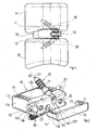
figure 2 est une vue en éclaté partiel du système selon l'invention, - la
figure 3 est une vue de dessus du système selon l'invention, - la
figure 4 est une vue en coupe selon la ligne IV - IV de lafigure 3 , - la
figure 5 est une vue en plan d'un pion d'ancrage, - la
figure 6 est une vue de dessus de la cage du système selon l'invention, - la
figure 7 est une vue en perspective de la cage selon l'invention, - la
figure 8 est une vue d'une autre forme de réalisation du pion d'ancrage selon l'invention, - la
figure 9 est une vue en coupe brisée, selon deux plans parallèles au plan sagittal, illustrant l'aptitude de pivotement limité de la plaque antérieure, - la
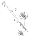
figure 10 est une vue en perspective d'un ancillaire de pose d'une cage du système selon l'invention, - la
figure 11 est une vue en perspective d'un amorçoir, - la
figure 12 est une vue en perspective d'un positionneur des pions, - la
figure 12a est une vue en coupe du positionneur selon lafigure 12 , - la
figure 13 est une vue en perspective d'un ancillaire de pose de la plaque antérieure, - la
figure 14 est une vue en coupe de l'ancillaire de pose de la plaque antérieure.
- the
figure 1 is a profile of the system in situation between two adjacent vertebrae, - the
figure 2 is a partial exploded view of the system according to the invention, - the
figure 3 is a top view of the system according to the invention, - the
figure 4 is a sectional view along line IV - IV of thefigure 3 , - the
figure 5 is a plan view of an anchor, - the
figure 6 is a top view of the cage of the system according to the invention, - the
figure 7 is a perspective view of the cage according to the invention, - the
figure 8 is a view of another embodiment of the anchor pin according to the invention, - the
figure 9 is a broken sectional view, in two planes parallel to the sagittal plane, illustrating the limited pivotability of the anterior plate, - the
figure 10 is a perspective view of an ancillary installation of a cage of the system according to the invention, - the
figure 11 is a perspective view of an initiator, - the
figure 12 is a perspective view of a pion positioner, - the
figure 12a is a sectional view of the positioner according to thefigure 12 , - the
figure 13 is a perspective view of an ancillary laying of the anterior plate, - the
figure 14 is a sectional view of the ancillary of the anterior plate.
Il est tout d'abord précisé que, sur les figures, les mêmes références désignent les mêmes éléments, quelle que soit la figure sur laquelle elles apparaissent et quelle que soit la forme de représentation de ces éléments. De même, si des éléments ne sont pas spécifiquement référencés sur l'une des figures, leurs références peuvent être aisément retrouvées en se reportant à une autre figure.It is first of all specified that, in the figures, the same references designate the same elements, whatever the figure on which they appear and whatever the form of representation of these elements. Similarly, if elements are not specifically referenced in one of the figures, their references can be easily found by referring to another figure.
Il est aussi précisé que les figures représentent essentiellement un mode de réalisation de l'objet selon l'invention, mais qu'il peut exister d'autres modes de réalisation qui répondent à la définition de cette invention.It is also stated that the figures essentially represent an embodiment of the object according to the invention, but that there may be other embodiments that meet the definition of this invention.
Il est en outre précisé que, lorsque, selon la définition de l'invention, l'objet de l'invention comporte "au moins un" élément ayant une fonction donnée, le mode de réalisation décrit peut comporter plusieurs de ces éléments. Réciproquement, si le mode de réalisation de l'objet selon l'invention tel qu'illustré comporte plusieurs éléments de fonction identique et si, dans la description, il n'est pas spécifié que l'objet selon cette invention doit obligatoirement comporter un nombre particulier de ces éléments, l'objet de l'invention pourra être défini comme comportant "au moins un" de ces éléments.It is furthermore specified that, when, according to the definition of the invention, the object of the invention comprises "at least one" element having a given function, the embodiment described may comprise several of these elements. Conversely, if the embodiment of the object according to the invention as illustrated has several elements of identical function and if, in the description, it is not specified that the object according to this invention must obligatorily comprise a number particular of these elements, the object of the invention may be defined as comprising "at least one" of these elements.
Il est enfin précisé que lorsque, dans la présente description, une expression définit à elle seule, sans mention particulière spécifique la concernant, un ensemble de caractéristiques structurelles, ces caractéristiques peuvent être prises, pour la définition de l'objet de la protection demandée, quand cela est techniquement possible, soit séparément, soit en combinaison totale et/ou partielle.Lastly, it is specified that when, in the present description, an expression defines, by itself, without a specific particular mention concerning it, a set of structural characteristics, these characteristics may be taken, for the definition of the object of the protection requested, when technically possible, either separately, or in full and / or partial combination.
La présente invention concerne un système pour réaliser une arthrodèse entre deux première et seconde vertèbres consécutives V1, V2,
Le système comporte une cage 10, généralement dénommée par les hommes du métier "cage intervertébrale" ou " cage intersomatique", apte à être interposée entre les deux vertèbres en remplacement du disque intervertébral qui était originellement situé entre ces deux vertèbres.The system comprises a
La cage est essentiellement définie dans une enveloppe parallélépipédique rectangle, ou similaire, de façon à comporter deux première et seconde faces opposées 11, 12, d'appui sur les corps vertébraux adjacents et une paroi latérale 13 réunissant ces deux faces opposées et se composant essentiellement de quatre portions de paroi ou assimilables, à savoir une portion antérieure 13a et une portion postérieure 13b normales au plan sagittal et deux portions 13c gauche et droite parallèles au plan sagittal ou inclinées par rapport à ce dernier. Les première et seconde faces opposées 11, 12 sont sensiblement planes ou convexes. Avantageusement la face supérieure est convexe tandis que la face inférieure est plane. Ces deux faces 11, 12 sont aptes à venir au contact respectivement des deux corps osseux des première et seconde vertèbres consécutives V1, V2, (
Le système selon l'invention comporte en outre des moyens pour stabiliser de manière postéro-antérieure par la cage 10 avec le corps osseux d'au moins l'une première V1 des deux vertèbres consécutives, afin de prévenir une migration postéro-antérieure secondaire de la cage 10, susceptible d'entraîner des dommages au niveau des tissus environnants.The system according to the invention further comprises means for stabilizing postero-anteriorly by the
Selon une caractéristique de l'invention, les moyens pour stabiliser de manière postéro-antérieure la cage 10 avec le corps osseux d'au moins l'une première V1 des deux vertèbres consécutives V1, V2, sont constitués par au moins un ensemble E1 comportant un élément d'ancrage 20, sous forme de pion ou de vis, l'élément d'ancrage comportant une tige 21 définie selon un premier axe longitudinal 121 entre une extrémité proximale 22 et une extrémité distale 23, l'extrémité distale étant conformée en extrémité pénétrante, de façon que la tige soit apte à être ancrée dans le corps osseux de la vertèbre V1 en pénétrant dans le corps osseux de cette vertèbre par son extrémité distale pénétrante 23, par impactage ou par vissage selon le cas. L'élément d'ancrage 20 comporte en outre une tête cylindrique 30, de préférence de révolution, ayant une longueur déterminée définie selon un deuxième axe longitudinal 131, ladite tête 30 étant solidaire de l'extrémité proximale 22 de la tige 21.According to one characteristic of the invention, the means for stabilizing postero-
Comme on peut le voir plus particulièrement en
Selon une variante de réalisation, comme représentée en
L'élément d'ancrage peut également être constitué par une vis et dans ce cas de figure les axes 121 et 131 seront confondus.The anchoring element may also be constituted by a screw and in this case the
L'ensemble E1 comporte aussi un logement 40 de forme sensiblement cylindrique, défini selon un troisième axe longitudinal 143 et réalisé dans la cage 10 de façon qu'il débouche notamment sur la face antérieure de la portion de paroi 13a par un orifice d'entrée 44, ce troisième axe longitudinal 143 faisant une direction déterminée par rapport au plan passant sensiblement par la seconde face 12 destinée à être en contact avec le corps osseux de la seconde vertèbre V2.The assembly E1 also comprises a
Le logement 40 débouche également sur la première face 11 par un orifice de sortie 45. Ce logement est en outre dotée d'une fente radiale 46 s'étendant de l'orifice d'entrée à l'orifice de sortie, cette fente débouchant dans la face 11.The
Le logement 40 a en outre un diamètre au moins égal à celui de la tête cylindrique 30 et est réalisé de façon que, lorsque la tête cylindrique 30 est enfichée dans ce logement 40, le premier axe longitudinal 121 de la tige 21 fasse avec le plan de la seconde face 12 un angle non nul β et que, lorsque la cage 10 est interposée entre les deux vertèbres consécutives V1, V2, la tige 21 pénètre de manière oblique dans le corps osseux de la première vertèbre V1 qui est au contact de la première face 11 et que la tête 30 par sa partie débordante du logement 40 puisse pénétrer dans le corps osseux adjacent.The
Selon une réalisation avantageuse et préférentielle, le logement 40 a une profondeur au moins égale à la longueur de la tête cylindrique 30 de façon que la tête cylindrique soit apte à y pénétrer en entier et que, comme illustré sur les figures et dans le but défini ci-après, elle n'émerge en aucune façon de la paroi latérale 13. On peut observer que cette tête 30 cylindrique présente une surface de butée 31, annulaire, adaptée à venir en butée contre un épaulement interne 47 du logement 40. En outre la tige 21 et la tête 30 présentent des formes en sapine 25, 25a, sous forme de collerette annulaire, agencées pour autoriser l'introduction de la tige 21 et de la tête 30 dans le corps osseux et pour s'opposer à leur extraction. De préférence au moins une des formes en sapine 25a de la tige, celle prévue pour être située immédiatement en regard de l'orifice de sortie, présente un diamètre supérieur à celui dudit orifice. Cette disposition après mise en place de l'élément d'ancrage 20 assure la fixation de ce dernier par rapport à la cage 10.According to an advantageous and preferred embodiment, the
Il est préférable que le troisième axe longitudinal 143, celui de l'orifice 40, fasse, avec le plan de la seconde face 12, un angle égal à l'angle non nul β défini auparavant.It is preferable that the third
Selon une réalisation avantageuse, le système comporte en outre un trou borgne réalisé dans la tête cylindrique 30 sensiblement suivant le deuxième axe longitudinal 131. Ce trou borgne est prévu pour recevoir un repère radiographique 38.According to an advantageous embodiment, the system further comprises a blind hole made in the
Le système peut avantageusement comporter en outre une plaque antérieure 70 venant en recouvrement au moins de l'entrée 44 du logement 40 pour empêcher la sortie de la tête cylindrique 30 hors de ce logement 40 après qu'elle y ait été enfichée, et des moyens pour solidariser la plaque antérieure 70 avec la cage 10. Ces moyens peuvent être de tout type, mais préférentiellement ils seront constitués d'une part par deux pattes latérales, élastiques 71 que comporte la dite plaque 70, ces pattes latérales présentant en extrémité des bossages 72 de rétention et d'autre part par des formes en creux 13d complémentaires de celles des bossages et prévues pour recevoir ces derniers, ces formes en creux 13d étant ménagées dans les portions de parois 13c gauche et droite de la cage 10. Avantageusement ces portions de parois 13c présentent chacune une gorge 13e apte à recevoir la patte correspondante 71 de la plaque antérieure 70, cette gorge 13e débouchant radialement dans la forme en creux 13d correspondante. Sous l'effet de l'élasticité des pattes 71, les bossages 72, lorsque la plaque antérieure est en place sur la cage, sont sollicités vers le fond des formes en creux 13d.The system may advantageously further comprise an
Selon la forme préférée de réalisation, les arêtes de la plaque antérieure 70, des pattes latérales 71 et des bossages 72 sont arrondies selon un rayon de courbure approprié afin que lors de la mise en place de la plaque antérieure, tous risques de lésions, par ces arêtes, de l'appareil veineux et des tissus adjacents soient écartés. De plus, pour notamment les mêmes raisons, l'extrémité libre de chaque patte latérale 71 est arrondie et chaque bossage 72 est cylindrique.According to the preferred embodiment, the edges of the
Toujours selon la forme préférée de réalisation, la profondeur de chaque gorge 13e est égale ou supérieure à l'épaisseur de chaque patte latérale afin qu'après mise en place de la plaque antérieure 70, les pattes latérales 71 ne soient pas en débordement par rapport aux faces externes à la cage, des parois 13c.Still according to the preferred embodiment, the depth of each
Pour faciliter la mise en place de la plaque antérieure 70, chaque gorge 13e est de forme évasée et s'élargit progressivement depuis la forme en creux 13d correspondante vers la face antérieure de la portion de paroi 13a. Toujours pour faciliter cette introduction, le fond plat de chaque gorge 13e est incliné latéralement vers l'extérieur depuis la face antérieure de la portion de paroi 13a, vers la forme en creux 13d et la face terminale de chaque bossage 72 est oblique par rapport à l'axe géométrique de révolution que possède ce bossage, et est parallèle lors de la mise en place de la plaque antérieure, au fond plat de la gorge correspondante. Lors de cette mise en place, la face terminale de chaque bossage vient glisser sur le fond de la gorge et compte tenu de l'oblicité de ce fond, les pattes élastiques 71 sous l'effet des efforts appliqués sur la face terminale de chaque bossage par le fond de chaque gorge, s'écartent angulairement l'une de l'autre et ce à l'encontre de l'action des forces élastiques internes. Par la suite, lorsque les bossages parviennent au droit de chaque forme en creux, les pattes élastiques 71 sont ramenées l'une vers l'autre sous l'effet des forces élastiques internes et les bossages 72 sont introduits dans les formes en creux 13d.To facilitate the introduction of the
La face terminale de chaque bossage 72 présente une facette arrière perpendiculaire à l'axe géométrique du dit bossage. De plus, toujours selon la forme préférée de réalisation, chaque bossage présente un méplat antérieur prévu pour venir en regard et contre une face plane de la forme en creux. De telles dispositions maximisent la rétentivité de la plaque 70 dans la cage 10.The end face of each
Pour obtenir de façon fiable une meilleure stabilisation postéro antérieure de la cage par rapport aux première et seconde vertèbres V1, V2, il est préférable que le système comporte au moins deux ensembles E1, E2, pour stabiliser la cage 10 avec respectivement les deux vertèbres.To reliably obtain a better postero-anterior stabilization of the cage with respect to the first and second vertebrae V1, V2, it is preferable that the system comprises at least two sets E1, E2, to stabilize the
Dans ce cas, les deux orifices 40 respectivement des deux ensembles E1, E2 sont réalisés de façon que, lorsque les têtes cylindriques 30 sont enfichées dans les orifices 40, les premiers axes longitudinaux 121 des deux tiges 21 fassent respectivement avec le plan de la seconde face 12 un angle β non nul, les deux angles β n'ayant pas obligatoirement la même valeur bien que cela soit préférable pour simplifier la réalisation industrielle du système et faciliter son implantation, les deux éléments d'ancrage 20 étant alors identiques.In this case, the two
De cette façon, lorsque la cage 10 est interposée entre les deux vertèbres V1, V2, la tige 21 de chaque ensemble pénètre dans le corps osseux de la vertèbre qui est au contact de l'une ou l'autre des première et seconde faces 11, 12 de la cage.In this way, when the
Dans ce cas, il est en outre avantageusement prévu que la plaque antérieure 70 soit conformée pour venir en recouvrement partiel des deux entrées 44 des deux orifices 40 respectivement des deux ensembles E1, E2. Préférentiellement, ce recouvrement n'est que partiel et la plaque antérieure 70, comme on peut le voir en
Selon la forme préférée de réalisation, l'amplitude du pivotement de la plaque antérieure est, à partir d'une position médiale, de cinq degrés vers le haut et de cinq degrés vers le bas. L'amplitude totale est donc de dix degrés.According to the preferred embodiment, the amplitude of the pivoting of the anterior plate is, from a medial position, five degrees up and five degrees down. The total amplitude is therefore ten degrees.
La cage 10, peut être de différentes formes et avoir différentes structures, comme celles que l'on trouve actuellement sur le marché. Cependant, elle aura, de préférence, une forme et une structure comme celle illustrée en
Comme défini précédemment, la cage 10 est inscrite dans un parallélépipède rectangle, avec des faces légèrement convexe pour l'une et plane pour l'autre pour s'adapter aux formes anatomiques des corps vertébraux et/ou pour des raisons de réalisation mécanique.As defined above, the
Elle peut en outre comporter au moins une percée traversante, réalisée entre les deux faces opposées 11, 12, cette percée étant conçue pour recevoir un substitut osseux ou un greffon osseux afin de favoriser, de façon connue en elle-même, l'arthrodèse entre les deux vertèbres V1, V2.It may also comprise at least one through-hole, made between the two
Mais elle peut aussi comporter une (ou plusieurs) percée traversante qui débouche sur sa paroi latérale 13 et de préférence communique avec la percée traversante débouchant sur ses deux faces opposées 11, 12.But it may also include one (or more) through-hole which opens on its
En outre, toutes les faces de la cage 10, mais essentiellement les deux faces opposées 11, 12, peuvent comporter des aspérités de toute forme, par exemple des picots ou analogues mais avantageusement des aspérités en dents de scie comme illustré notamment sur les
La cage 10 peut être réalisée en tout matériau biocompatible, avantageusement en PEEK (sigle anglais d'une matière plastique thermostable connue en français sous le nom de poly-éther-éther-cétone), comme d'ailleurs tous les autres éléments du système selon l'invention, à savoir les éléments d'ancrage 20, la plaque antérieure 70, les pattes 71 et les bossages 72.The
De plus, quand la cage est en un matériau comme du PEEK, elle est radio-transparente. Dans ce cas, elle peut avantageusement comporter, en des endroits choisis et bien connus des personnes du métier, des logements 90 aptes à recevoir des inserts en un matériau radio-opaque permettant de vérifier par radiographie la position de la cage 10 par rapport aux vertèbres.In addition, when the cage is made of a material such as PEEK, it is radio-transparent. In this case, it may advantageously include, in selected locations and well known to those skilled in the art,
Le système selon l'invention s'implante entre deux vertèbres V1, V2 de la façon suivante à l'aide d'un outil ancillaire 500 tel que représenté en
Au moyen de cet ancillaire, le praticien positionne la cage 10 entre les deux vertèbres V1, V2.By means of this ancillary device, the practitioner positions the
Puis, tout en maintenant l'ancillaire 500 lié à la cage 10, au moyen d'un amorçoir 510, il réalise, dans le corps osseux de chacune des deux vertèbres, un avant-trou d'une section inférieure à celle de la tige 21. Dans ce but l'amorçoir 510 est tour à tour engagé dans les canons de guidage 501.Then, while maintaining the ancillary 500 linked to the
Ces deux avant-trous réalisés, il peut, toujours par référence à cet ancillaire, mettre en place un premier pion d'ancrage 20 par l'intermédiaire de cet ancillaire 500 et d'un positionneur 520 apte, en vue de la mise en place du pion 20, à être introduit dans le canon de guidage 501 correspondant.These two pre-holes made, it can, still with reference to this ancillary, set up a
Ce positionneur 520 est avantageusement constitué d'un corps tubulaire 521 comportant une zone distale formant une chambre 522 prévue pour recevoir le pion à fixer. Une ouverture radiale 523 est pratiquée dans le corps tubulaire 521 pour l'introduction du pion 20 dans la chambre 522.This
Le positionneur 520 est de plus doté d'un poussoir 524, sous forme de tige cylindrique, monté en coulissement dans le corps tubulaire, doté extérieurement à ce dernier d'un bouton de manoeuvre 525. Ce poussoir est apte, par déplacement dans le corps tubulaire 521 à venir pousser le pion et le chasser hors de la chambre 522 et hors du corps tubulaire 521.The
Avantageusement, le corps tubulaire, en extrémité distale est doté d'un lamage 527 prévu pour être engagé autour d'un des canons de guidage 501. Une telle disposition assure un positionnement précis du positionneur 520 par rapport au canon et par voie de conséquence par rapport à la cage 10.Advantageously, the tubular body, at the distal end, is provided with a
La zone distale du corps du positionneur est dotée d'une fente diamétrale 528 qui confère à cette zone une fonction de pince. On peut voir que cette fente diamétrale traverse de part en part la chambre 522 et prend naissance en amont de la chambre et court jusqu'à l'extrémité distale du positionneur. Ainsi le pion 20 est maintenu en place dans le corps tubulaire 521 par de légères forces radiales de serrage suffisantes pour assurer son maintien dans le corps et éviter sa chute mais suffisamment faibles pour écarter tous risques de détérioration des formes saillantes en sapine 25, 25a lors de son coulissement vers l'extrémité distale du corps tubulaire. En combinaison avec cette caractéristique, le poussoir 524 est sollicité vers la chambre par un organe élastique 526 formé par un ressort à spires. Ce ressort à spires est monté dans le corps 521 autour du poussoir. En raison de ces dispositions, le pion 20 est maintenu dans la chambre tant par les forces radiales de serrage que par l'action axiale du poussoir, étant entendu que cette action axiale, dont l'intensité dépend du degré de compression du ressort à spires, est insuffisante à elle seule pour pousser le pion hors de la chambre.The distal zone of the positioner body is provided with a
En vue de de la fixation de chaque pion 20 dans le corps vertébral correspondant, le positionneur 520, par son lamage 527 est positionné sur le canon de perçage et le poussoir 524 est actionné en vue de chasser le pion 20 vers le logement 40 de la cage 10 et vers le corps vertébral. Une force est appliquée ensuite à l'aide d'un maillet sur le bouton 525 afin de finaliser la mise en place du pion dans le corps vertébral. Il y a lieu de noter que le déplacement axial du poussoir se trouve limité par le bouton de manoeuvre 525. Ce déplacement est suffisamment pour que la forme en sapine 24a que possède le pion puisse être amenée en regard de l'orifice de sortie du logement 40 correspondant, extérieurement à ce dernier.
Après mise en place des pions 20 dans les corps vertébraux, l'ancillaire 500 est retiré et la plaque antérieure 70 est placée sur la portion antérieure 13a de paroi latérale de la cage à l'aide d'un ancillaire de pose 530 tel que celui représenté en
After placement of the
Selon la forme préférée de réalisation, cet ancillaire de pose comprend sur un même bâti longiforme 531, une pince 532 dotée de deux mâchoires 533 de préhension de la plaque antérieure, articulées l'une à l'autre et associées chacune à un levier de manoeuvre 534. Selon la forme préférée de réalisation, l'extrémité de chaque mâchoire 533 est agencée en feuillure 536 tant pour faciliter la préhension de la plaque antérieure 70 par ses bordures longitudinales que la solidarisation de la plaque antérieure à cage 10. On peut remarquer également que l'articulation des deux mâchoires 533 est formée par une cloison transversale 535 élastique, enracinée aux deux mâchoires 533. Avantageusement, l'une des deux mâchoires 533 et le levier associé 534 sont formés par la partie distale du bâti 531. Le bâti porte de plus un moyen de manoeuvre des mâchoires 533 agissant sur les leviers 534. On peut remarquer que la distance entre la cloison d'articulation 535 et le point d'application des efforts par le moyen de manoeuvre sur les leviers 534 est moindre que la distance entre la cloison d'articulation et les feuillures d'extrémité 536. On réalise ainsi une démultiplication des efforts, au niveau des mâchoires de préhension de la plaque, tout en exerçant un effort moindre au niveau du levier 534. Cette disposition permet d'assurer la préhension, de la plaque, dans de bonnes conditions, et de garantir sa tenue, sur l'instrument, durant les phases de manipulation avant mise en place.According to the preferred embodiment, this anchoring device comprises on a same
Dans la forme préférée de réalisation, le moyen de manoeuvre est formé d'une tige537 montée en vissage dans le corps du bâti, ledit corps étant tubulaire. L'extrémité proximale de la tige reçoit un bouton 538 de manoeuvre en rotation. L'extrémité distale de la tige, qui présente une forme sphérique, s'engage entre les leviers 534 pour agir radialement sur ces derniers et les écarter angulairement l'un de l'autre. Est ainsi réalisé le serrage des mâchoires 533 sur la plaque antérieure 70.In the preferred embodiment, the operating means is formed of a
Selon la forme préférée de réalisation, la tige 537 à proximité de son extrémité proximale comporte un collet fileté 539 engagé en vissage dans un taraudage traversant formé dans la cloison terminale 540 que le corps tubulaire 531 comporte à son extrémité proximale. A distance de ce premier collet 539, la tige 537 comporte un second collet 541 également fileté. Une telle disposition, dans le cas d'un dévissage total du premier collet 539, s'oppose à la perte de la tige, le second collet 541 venant en butée contre la cloison terminale 540. Mais cette disposition autorise cependant le démontage de la tige, le second collet, pour ce faire, étant alors engagé en vissage dans le taraudage de la cloison terminale.According to the preferred embodiment, the
Claims (12)
- System for performing arthrodesis between two consecutive first and second vertebrae (V1, V2), more particularly cervical vertebrae, said system having:• a cage (10) that can be interposed between said two vertebrae to replace the intervertebral disc that was originally situated between these two vertebrae, said cage being defined within a rectangular parallelepipedal envelope, said cage having two opposite first and second bearing faces (11, 12) that can come into contact with the two osseous bodies of said two vertebrae (V1, V2), respectively, when the cage (10) is interposed between these, and a lateral wall (13) joining said two opposite faces (11, 12), said lateral wall being composed of four wall portions, namely an anterior portion (13a) and a posterior portion (13b), which are perpendicular to the sagittal plane, and two left and right portions (13c), and• means for stabilizing said cage with the osseous body of at least a first (V1) of the two consecutive vertebrae, said means being means for posterior-anterior stabilization and being formed by two assemblies (E1, E2) that each have at least:said system additionally having an anterior plate (70) that comes to partially cover at least the inlet (44) of the seat (40) in order to prevent the cylindrical head (30) from leaving each seat (40) after it has been engaged therein, and means for rigidly connecting this anterior plate to the cage (10), which means are formed, on the one hand, by two lateral tabs (71) arranged on said plate, these lateral tabs (71) having retention bosses (72) at their ends, and, on the other hand, by recessed formations (13d) complementing the bosses and designed to receive the latter, these recessed formations (13d) being formed in the left and right walls (13c) of the cage (10),- an anchoring element (20), in the form of a peg, having:• a rod (21) defined along a first longitudinal axis (121) between a proximal end (22) and a distal end (23), the distal end being configured as a penetrating end, said rod being able to be anchored in the osseous body of the first vertebra by penetrating into this osseous body with its penetrating distal end,• a cylindrical head (30) having a specific length defined along a second longitudinal axis (131), said head being rigidly connected to said rod and being formed as the proximal end of the latter,- and a seat (40) of substantially cylindrical shape defined along a third longitudinal axis (143) and formed in said cage (10) in such a way that it opens out on said lateral wall (13) via an inlet orifice (44) and on the first bearing face via an outlet orifice (45), said third longitudinal axis (143) forming a defined angle with respect to the plane passing substantially through the second bearing face (12), this seat (40) being provided with a radial slit (46) extending from one orifice to the other and opening out on the first bearing face (11), and said seat additionally being formed in such a way that, when said cylindrical head (30) is engaged in the seat (40), the first longitudinal axis (121) of the rod forms, with the plane of the second face (12), a non-zero angle (β), and, when said cage (10) is interposed between the two consecutive vertebrae (V1, V2), said rod (21) protrudes from the seat through the outlet orifice (45) and said head (30) protrudes through the radial slit (46) and both of them penetrate into the osseous body of the first vertebra (V1) that is in contact with this first face (11),
characterized in that the edges of the anterior plate (70), of the lateral tabs (71) and of the bosses (72) are rounded, in that the free end of each lateral tab (71) is rounded, in that each boss (72) is cylindrical, in that said plate (70) comes to partially cover the two inlets (44) of the two seats (40), respectively, of the two assemblies (E1, E2), and in that the anterior plate (70) is mounted on the cage with a capacity for limited pivoting about the geometric axis defined by the bosses (72) and the recessed formations (13d), this geometric axis of pivoting being parallel to the anterior face of the wall portion (13a), such that the migration of one of the pegs towards the plate translates into a thrusting force exerted by the anterior end face of this peg against the corresponding longitudinal edge of the inner face of the anterior plate (70), and, consequently, into the tilting of this anterior plate (70) towards the other peg and more particularly towards the inlet (44) of the seat (40) that receives this other peg. - System according to Claim 1, characterized in that the first and second longitudinal axes (121, 131) are coincident.
- System according to Claim 1 or 2, characterized in that the seat (40) has a depth at least equal to the length of said cylindrical head (30), such that said cylindrical head is able to penetrate fully therein.
- System according to the preceding claim, characterized in that the seat (40) has an inner shoulder (47) against which an annular abutment surface (31) of the head bears when the anchoring element is in place with respect to the cage.
- System according to any one of the preceding claims, characterized in that the rod (21) and the head (30) have fir-tree shapes (25, 25a), in the form of an annular collar, which are designed to permit the introduction of the rod and of the head into the osseous body and to oppose their removal from same.
- System according to the preceding claim, characterized in that the fir-tree shape (25a) of the rod (21) intended to be situated immediately opposite the outlet orifice (45) of the seat (40) has a diameter greater than the diameter of said orifice.
- System according to any one of the preceding claims, characterized in that said third longitudinal axis (143) forms, with the plane of the second face (12), an angle equal to said non-zero angle (β).
- System according to any one of the preceding claims, characterized in that the left and right walls (13c) each have a groove (13e) that is able to receive the corresponding tab (71) of the anterior plate (70), in that each groove (13e) opens out radially in the corresponding recessed formation (13d), and in that the depth of each groove (13e) is equal to or greater than the thickness of each lateral tab (71) such that, after the anterior plate (70) has been fitted in place, the lateral tabs (71) do not protrude, with respect to the outer faces of the cage, from the walls (13c).
- System according to Claim 8, characterized in that each groove (13e) has a flared shape and widens progressively from the corresponding recessed formation (13d) towards the anterior face of the wall portion (13a), in that the flat bottom of each groove (13e) is inclined laterally outwards from the anterior face of the wall portion (13a) towards the recessed formation (13d), and in that the end face of each boss (72) is oblique with respect to the geometric axis of revolution of this boss and is parallel, when the anterior plate is fitted in place, to the flat bottom of the corresponding groove.
- System according to any one of the preceding claims, characterized in that the two seats (40) of the two assemblies are formed in such a way that, when the cylindrical head (30) of each assembly is engaged in the corresponding orifice, the first longitudinal axes (121) of the two rods (21) form respectively with the plane of the second face (12) a non-zero angle (β) and, when said cage (10) is interposed between the two vertebrae, the rods (21) penetrate respectively into the osseous bodies of the two vertebrae (V1, V2) which are respectively in contact with the first and second faces (11, 12) of the cage (10).
- Positioner (520) by which a peg (20) of a system according to any one of the preceding claims is placed in a vertebral body, characterized in that it comprises a tubular body (521) having a distal zone that forms a chamber (522) intended to receive the peg to be introduced into the vertebral body, said chamber (522) being provided with a radial opening (523) for introduction of the peg (20), said positioner having a pusher (524) in the form of a cylindrical rod which is mounted so as to slide in the tubular body and is equipped externally with a control button (525).
- Positioner (520) according to the preceding claim, characterized in that the distal zone of the tubular body (521) is provided with a diametral slit (528) that gives this zone a gripping function, and in that the pusher (524) is stressed towards the chamber by an elastic member (526).
Applications Claiming Priority (1)
| Application Number | Priority Date | Filing Date | Title |
|---|---|---|---|
| FR1002189A FR2960419B1 (en) | 2010-05-25 | 2010-05-25 | SYSTEM FOR REALIZING ARTHRODESIS BETWEEN TWO VERTEBRATES |
Publications (2)
| Publication Number | Publication Date |
|---|---|
| EP2389903A1 EP2389903A1 (en) | 2011-11-30 |
| EP2389903B1 true EP2389903B1 (en) | 2015-06-17 |
Family
ID=43416222
Family Applications (1)
| Application Number | Title | Priority Date | Filing Date |
|---|---|---|---|
| EP11167529.4A Active EP2389903B1 (en) | 2010-05-25 | 2011-05-25 | System for performing arthrodesis between two vertebrae and installation accessories |
Country Status (3)
| Country | Link |
|---|---|
| EP (1) | EP2389903B1 (en) |
| ES (1) | ES2546835T3 (en) |
| FR (1) | FR2960419B1 (en) |
Family Cites Families (7)
| Publication number | Priority date | Publication date | Assignee | Title |
|---|---|---|---|---|
| GB8718627D0 (en) | 1987-08-06 | 1987-09-09 | Showell A W Sugicraft Ltd | Spinal implants |
| EP1769777A1 (en) * | 1997-04-25 | 2007-04-04 | Stryker France S.A. | Two parts interbody implant |
| US6629998B1 (en) * | 2000-08-23 | 2003-10-07 | Chih-I Lin | Intervertebral retrieval device |
| US6972019B2 (en) * | 2001-01-23 | 2005-12-06 | Michelson Gary K | Interbody spinal implant with trailing end adapted to receive bone screws |
| US6929647B2 (en) * | 2001-02-21 | 2005-08-16 | Howmedica Osteonics Corp. | Instrumentation and method for implant insertion |
| EP2457541A1 (en) * | 2003-02-06 | 2012-05-30 | Synthes GmbH | Implant between vertebrae |
| US20080249569A1 (en) * | 2007-04-03 | 2008-10-09 | Warsaw Orthopedic, Inc. | Implant Face Plates |
-
2010
- 2010-05-25 FR FR1002189A patent/FR2960419B1/en not_active Expired - Fee Related
-
2011
- 2011-05-25 ES ES11167529.4T patent/ES2546835T3/en active Active
- 2011-05-25 EP EP11167529.4A patent/EP2389903B1/en active Active
Also Published As
| Publication number | Publication date |
|---|---|
| FR2960419B1 (en) | 2013-03-15 |
| ES2546835T3 (en) | 2015-09-29 |
| EP2389903A1 (en) | 2011-11-30 |
| FR2960419A1 (en) | 2011-12-02 |
Similar Documents
| Publication | Publication Date | Title |
|---|---|---|
| EP1299054B1 (en) | Intersomatic implant | |
| CA2287523C (en) | Two-part intersomatic implant | |
| CA2299166C (en) | Implant, in particular front cervical plate | |
| EP2231074B1 (en) | Intervertebral stabilization assembly for arthrodesis, comprising an impaction cage body, and an ancillary device for implanting same | |
| EP1962730B1 (en) | Assembly comprising an implant for replacing a vertebral body and a spinal distraction tool | |
| EP2779953A2 (en) | Spinal intervertebral implant | |
| WO1997023174A1 (en) | Interbody-type intervertebral implant | |
| FR2715293A1 (en) | Vertebral interbody fusion cage. | |
| FR2763836A1 (en) | CERVICAL INTERVERTEBRAL CAGE | |
| FR2794362A1 (en) | INTERVERTEBRAL IMPLANT AND INSTALLATION ASSEMBLY OF SUCH AN IMPLANT | |
| EP0996383A1 (en) | Apparatus for interlocking two contiguous, in particular lumbar, vertebrae | |
| EP1980222A1 (en) | System for replacing a disc between two vertebrae | |
| EP0844849B1 (en) | Intrafocal pin | |
| FR2977474A1 (en) | INTERSOMATIC CAGE, IN PARTICULAR OF THE TRANSFORAMINAL TYPE | |
| FR2660856A1 (en) | Lower radioulnar prosthesis | |
| EP2440161A1 (en) | Intervertebral implant and tool for placing same | |
| EP3310282B1 (en) | Implant for the fixation of bone elements | |
| FR2764795A1 (en) | Inervertebral spinal fixation cage | |
| FR2759900A1 (en) | Ancillary instrument for fitting components of ankle joint prosthesis | |
| FR2965169A1 (en) | Intervertebral cage for treating degenerative rachis, has body interposed between two vertebrae, where cavity is realized in body, and crossing cylindrical opening comprising cross section that is on shape of polygonal | |
| WO2018024617A1 (en) | Deployable implant | |
| EP2389903B1 (en) | System for performing arthrodesis between two vertebrae and installation accessories | |
| EP2638880A1 (en) | Intervertebral cage | |
| FR2929504A1 (en) | Prosthesis assembly for accompanying intervertebral movement, has nose rotated to simultaneously induce opening of intervertebral space and displacement of cage body similar to that of cam, when nose is introduced into intervertebral space | |
| FR2923158A1 (en) | INTERVERTEBRAL IMPLANT FOR IMMOBILIZING A VERTEBRE IN RELATION TO ANOTHER AND INSTRUMENT OF INSTALLATION OF THIS IMPLANT. |
Legal Events
| Date | Code | Title | Description |
|---|---|---|---|
| AK | Designated contracting states |
Kind code of ref document: A1 Designated state(s): AL AT BE BG CH CY CZ DE DK EE ES FI FR GB GR HR HU IE IS IT LI LT LU LV MC MK MT NL NO PL PT RO RS SE SI SK SM TR |
|
| AX | Request for extension of the european patent |
Extension state: BA ME |
|
| PUAI | Public reference made under article 153(3) epc to a published international application that has entered the european phase |
Free format text: ORIGINAL CODE: 0009012 |
|
| 17P | Request for examination filed |
Effective date: 20111214 |
|
| 17Q | First examination report despatched |
Effective date: 20140319 |
|
| GRAP | Despatch of communication of intention to grant a patent |
Free format text: ORIGINAL CODE: EPIDOSNIGR1 |
|
| INTG | Intention to grant announced |
Effective date: 20150109 |
|
| GRAS | Grant fee paid |
Free format text: ORIGINAL CODE: EPIDOSNIGR3 |
|
| GRAA | (expected) grant |
Free format text: ORIGINAL CODE: 0009210 |
|
| AK | Designated contracting states |
Kind code of ref document: B1 Designated state(s): AL AT BE BG CH CY CZ DE DK EE ES FI FR GB GR HR HU IE IS IT LI LT LU LV MC MK MT NL NO PL PT RO RS SE SI SK SM TR |
|
| AX | Request for extension of the european patent |
Extension state: BA ME |
|
| REG | Reference to a national code |
Ref country code: GB Ref legal event code: FG4D Free format text: NOT ENGLISH |
|
| REG | Reference to a national code |
Ref country code: CH Ref legal event code: EP |
|
| REG | Reference to a national code |
Ref country code: AT Ref legal event code: REF Ref document number: 731474 Country of ref document: AT Kind code of ref document: T Effective date: 20150715 |
|
| REG | Reference to a national code |
Ref country code: IE Ref legal event code: FG4D Free format text: LANGUAGE OF EP DOCUMENT: FRENCH |
|
| REG | Reference to a national code |
Ref country code: DE Ref legal event code: R096 Ref document number: 602011017143 Country of ref document: DE |
|
| REG | Reference to a national code |
Ref country code: ES Ref legal event code: FG2A Ref document number: 2546835 Country of ref document: ES Kind code of ref document: T3 Effective date: 20150929 |
|
| PG25 | Lapsed in a contracting state [announced via postgrant information from national office to epo] |
Ref country code: HR Free format text: LAPSE BECAUSE OF FAILURE TO SUBMIT A TRANSLATION OF THE DESCRIPTION OR TO PAY THE FEE WITHIN THE PRESCRIBED TIME-LIMIT Effective date: 20150617 Ref country code: FI Free format text: LAPSE BECAUSE OF FAILURE TO SUBMIT A TRANSLATION OF THE DESCRIPTION OR TO PAY THE FEE WITHIN THE PRESCRIBED TIME-LIMIT Effective date: 20150617 Ref country code: NO Free format text: LAPSE BECAUSE OF FAILURE TO SUBMIT A TRANSLATION OF THE DESCRIPTION OR TO PAY THE FEE WITHIN THE PRESCRIBED TIME-LIMIT Effective date: 20150917 Ref country code: LT Free format text: LAPSE BECAUSE OF FAILURE TO SUBMIT A TRANSLATION OF THE DESCRIPTION OR TO PAY THE FEE WITHIN THE PRESCRIBED TIME-LIMIT Effective date: 20150617 |
|
| REG | Reference to a national code |
Ref country code: AT Ref legal event code: MK05 Ref document number: 731474 Country of ref document: AT Kind code of ref document: T Effective date: 20150617 |
|
| REG | Reference to a national code |
Ref country code: LT Ref legal event code: MG4D Ref country code: NL Ref legal event code: MP Effective date: 20150617 |
|
| REG | Reference to a national code |
Ref country code: RO Ref legal event code: EPE |
|
| PG25 | Lapsed in a contracting state [announced via postgrant information from national office to epo] |
Ref country code: LV Free format text: LAPSE BECAUSE OF FAILURE TO SUBMIT A TRANSLATION OF THE DESCRIPTION OR TO PAY THE FEE WITHIN THE PRESCRIBED TIME-LIMIT Effective date: 20150617 Ref country code: BG Free format text: LAPSE BECAUSE OF FAILURE TO SUBMIT A TRANSLATION OF THE DESCRIPTION OR TO PAY THE FEE WITHIN THE PRESCRIBED TIME-LIMIT Effective date: 20150917 Ref country code: RS Free format text: LAPSE BECAUSE OF FAILURE TO SUBMIT A TRANSLATION OF THE DESCRIPTION OR TO PAY THE FEE WITHIN THE PRESCRIBED TIME-LIMIT Effective date: 20150617 Ref country code: GR Free format text: LAPSE BECAUSE OF FAILURE TO SUBMIT A TRANSLATION OF THE DESCRIPTION OR TO PAY THE FEE WITHIN THE PRESCRIBED TIME-LIMIT Effective date: 20150918 |
|
| PG25 | Lapsed in a contracting state [announced via postgrant information from national office to epo] |
Ref country code: EE Free format text: LAPSE BECAUSE OF FAILURE TO SUBMIT A TRANSLATION OF THE DESCRIPTION OR TO PAY THE FEE WITHIN THE PRESCRIBED TIME-LIMIT Effective date: 20150617 |
|
| PG25 | Lapsed in a contracting state [announced via postgrant information from national office to epo] |
Ref country code: PL Free format text: LAPSE BECAUSE OF FAILURE TO SUBMIT A TRANSLATION OF THE DESCRIPTION OR TO PAY THE FEE WITHIN THE PRESCRIBED TIME-LIMIT Effective date: 20150617 Ref country code: PT Free format text: LAPSE BECAUSE OF FAILURE TO SUBMIT A TRANSLATION OF THE DESCRIPTION OR TO PAY THE FEE WITHIN THE PRESCRIBED TIME-LIMIT Effective date: 20151019 Ref country code: AT Free format text: LAPSE BECAUSE OF FAILURE TO SUBMIT A TRANSLATION OF THE DESCRIPTION OR TO PAY THE FEE WITHIN THE PRESCRIBED TIME-LIMIT Effective date: 20150617 Ref country code: IS Free format text: LAPSE BECAUSE OF FAILURE TO SUBMIT A TRANSLATION OF THE DESCRIPTION OR TO PAY THE FEE WITHIN THE PRESCRIBED TIME-LIMIT Effective date: 20151017 Ref country code: SK Free format text: LAPSE BECAUSE OF FAILURE TO SUBMIT A TRANSLATION OF THE DESCRIPTION OR TO PAY THE FEE WITHIN THE PRESCRIBED TIME-LIMIT Effective date: 20150617 |
|
| REG | Reference to a national code |
Ref country code: DE Ref legal event code: R097 Ref document number: 602011017143 Country of ref document: DE |
|
| PLBE | No opposition filed within time limit |
Free format text: ORIGINAL CODE: 0009261 |
|
| STAA | Information on the status of an ep patent application or granted ep patent |
Free format text: STATUS: NO OPPOSITION FILED WITHIN TIME LIMIT |
|
| PG25 | Lapsed in a contracting state [announced via postgrant information from national office to epo] |
Ref country code: DK Free format text: LAPSE BECAUSE OF FAILURE TO SUBMIT A TRANSLATION OF THE DESCRIPTION OR TO PAY THE FEE WITHIN THE PRESCRIBED TIME-LIMIT Effective date: 20150617 |
|
| 26N | No opposition filed |
Effective date: 20160318 |
|
| REG | Reference to a national code |
Ref country code: FR Ref legal event code: PLFP Year of fee payment: 6 |
|
| PG25 | Lapsed in a contracting state [announced via postgrant information from national office to epo] |
Ref country code: SI Free format text: LAPSE BECAUSE OF FAILURE TO SUBMIT A TRANSLATION OF THE DESCRIPTION OR TO PAY THE FEE WITHIN THE PRESCRIBED TIME-LIMIT Effective date: 20150617 |
|
| REG | Reference to a national code |
Ref country code: IE Ref legal event code: MM4A |
|
| REG | Reference to a national code |
Ref country code: FR Ref legal event code: PLFP Year of fee payment: 7 |
|
| PG25 | Lapsed in a contracting state [announced via postgrant information from national office to epo] |
Ref country code: IE Free format text: LAPSE BECAUSE OF NON-PAYMENT OF DUE FEES Effective date: 20160525 |
|
| PG25 | Lapsed in a contracting state [announced via postgrant information from national office to epo] |
Ref country code: NL Free format text: LAPSE BECAUSE OF FAILURE TO SUBMIT A TRANSLATION OF THE DESCRIPTION OR TO PAY THE FEE WITHIN THE PRESCRIBED TIME-LIMIT Effective date: 20150617 Ref country code: SE Free format text: LAPSE BECAUSE OF FAILURE TO SUBMIT A TRANSLATION OF THE DESCRIPTION OR TO PAY THE FEE WITHIN THE PRESCRIBED TIME-LIMIT Effective date: 20150617 |
|
| REG | Reference to a national code |
Ref country code: FR Ref legal event code: PLFP Year of fee payment: 8 |
|
| PG25 | Lapsed in a contracting state [announced via postgrant information from national office to epo] |
Ref country code: SM Free format text: LAPSE BECAUSE OF FAILURE TO SUBMIT A TRANSLATION OF THE DESCRIPTION OR TO PAY THE FEE WITHIN THE PRESCRIBED TIME-LIMIT Effective date: 20150617 Ref country code: HU Free format text: LAPSE BECAUSE OF FAILURE TO SUBMIT A TRANSLATION OF THE DESCRIPTION OR TO PAY THE FEE WITHIN THE PRESCRIBED TIME-LIMIT; INVALID AB INITIO Effective date: 20110525 Ref country code: CY Free format text: LAPSE BECAUSE OF FAILURE TO SUBMIT A TRANSLATION OF THE DESCRIPTION OR TO PAY THE FEE WITHIN THE PRESCRIBED TIME-LIMIT Effective date: 20150617 |
|
| PG25 | Lapsed in a contracting state [announced via postgrant information from national office to epo] |
Ref country code: MK Free format text: LAPSE BECAUSE OF FAILURE TO SUBMIT A TRANSLATION OF THE DESCRIPTION OR TO PAY THE FEE WITHIN THE PRESCRIBED TIME-LIMIT Effective date: 20150617 |
|
| PG25 | Lapsed in a contracting state [announced via postgrant information from national office to epo] |
Ref country code: AL Free format text: LAPSE BECAUSE OF FAILURE TO SUBMIT A TRANSLATION OF THE DESCRIPTION OR TO PAY THE FEE WITHIN THE PRESCRIBED TIME-LIMIT Effective date: 20150617 |
|
| PGFP | Annual fee paid to national office [announced via postgrant information from national office to epo] |
Ref country code: FR Payment date: 20190328 Year of fee payment: 9 |
|
| PGFP | Annual fee paid to national office [announced via postgrant information from national office to epo] |
Ref country code: LU Payment date: 20190416 Year of fee payment: 9 |
|
| PGFP | Annual fee paid to national office [announced via postgrant information from national office to epo] |
Ref country code: CZ Payment date: 20190418 Year of fee payment: 9 Ref country code: MC Payment date: 20190423 Year of fee payment: 9 Ref country code: IT Payment date: 20190514 Year of fee payment: 9 Ref country code: ES Payment date: 20190606 Year of fee payment: 9 Ref country code: DE Payment date: 20190510 Year of fee payment: 9 |
|
| PGFP | Annual fee paid to national office [announced via postgrant information from national office to epo] |
Ref country code: TR Payment date: 20190514 Year of fee payment: 9 Ref country code: MT Payment date: 20190425 Year of fee payment: 9 Ref country code: RO Payment date: 20190423 Year of fee payment: 9 Ref country code: BE Payment date: 20190528 Year of fee payment: 9 |
|
| PGFP | Annual fee paid to national office [announced via postgrant information from national office to epo] |
Ref country code: CH Payment date: 20190517 Year of fee payment: 9 |
|
| PGFP | Annual fee paid to national office [announced via postgrant information from national office to epo] |
Ref country code: GB Payment date: 20190516 Year of fee payment: 9 |
|
| REG | Reference to a national code |
Ref country code: DE Ref legal event code: R119 Ref document number: 602011017143 Country of ref document: DE |
|
| PG25 | Lapsed in a contracting state [announced via postgrant information from national office to epo] |
Ref country code: CZ Free format text: LAPSE BECAUSE OF NON-PAYMENT OF DUE FEES Effective date: 20200525 Ref country code: LI Free format text: LAPSE BECAUSE OF NON-PAYMENT OF DUE FEES Effective date: 20200531 Ref country code: RO Free format text: LAPSE BECAUSE OF NON-PAYMENT OF DUE FEES Effective date: 20200525 Ref country code: MC Free format text: LAPSE BECAUSE OF NON-PAYMENT OF DUE FEES Effective date: 20200602 Ref country code: CH Free format text: LAPSE BECAUSE OF NON-PAYMENT OF DUE FEES Effective date: 20200531 |
|
| REG | Reference to a national code |
Ref country code: BE Ref legal event code: MM Effective date: 20200531 |
|
| GBPC | Gb: european patent ceased through non-payment of renewal fee |
Effective date: 20200525 |
|
| PG25 | Lapsed in a contracting state [announced via postgrant information from national office to epo] |
Ref country code: LU Free format text: LAPSE BECAUSE OF NON-PAYMENT OF DUE FEES Effective date: 20200525 |
|
| PG25 | Lapsed in a contracting state [announced via postgrant information from national office to epo] |
Ref country code: GB Free format text: LAPSE BECAUSE OF NON-PAYMENT OF DUE FEES Effective date: 20200525 Ref country code: FR Free format text: LAPSE BECAUSE OF NON-PAYMENT OF DUE FEES Effective date: 20200531 |
|
| PG25 | Lapsed in a contracting state [announced via postgrant information from national office to epo] |
Ref country code: BE Free format text: LAPSE BECAUSE OF NON-PAYMENT OF DUE FEES Effective date: 20200531 Ref country code: DE Free format text: LAPSE BECAUSE OF NON-PAYMENT OF DUE FEES Effective date: 20201201 |
|
| REG | Reference to a national code |
Ref country code: ES Ref legal event code: FD2A Effective date: 20211006 |
|
| PG25 | Lapsed in a contracting state [announced via postgrant information from national office to epo] |
Ref country code: IT Free format text: LAPSE BECAUSE OF NON-PAYMENT OF DUE FEES Effective date: 20200525 |
|
| PG25 | Lapsed in a contracting state [announced via postgrant information from national office to epo] |
Ref country code: ES Free format text: LAPSE BECAUSE OF NON-PAYMENT OF DUE FEES Effective date: 20200526 |
|
| PG25 | Lapsed in a contracting state [announced via postgrant information from national office to epo] |
Ref country code: TR Free format text: LAPSE BECAUSE OF NON-PAYMENT OF DUE FEES Effective date: 20200525 Ref country code: MT Free format text: LAPSE BECAUSE OF NON-PAYMENT OF DUE FEES Effective date: 20200525 |