EP2389901B1 - An implant for cartilage repair - Google Patents
An implant for cartilage repair Download PDFInfo
- Publication number
- EP2389901B1 EP2389901B1 EP10163721A EP10163721A EP2389901B1 EP 2389901 B1 EP2389901 B1 EP 2389901B1 EP 10163721 A EP10163721 A EP 10163721A EP 10163721 A EP10163721 A EP 10163721A EP 2389901 B1 EP2389901 B1 EP 2389901B1
- Authority
- EP
- European Patent Office
- Prior art keywords
- implant
- cartilage
- bone
- contact surface
- coating
- Prior art date
- Legal status (The legal status is an assumption and is not a legal conclusion. Google has not performed a legal analysis and makes no representation as to the accuracy of the status listed.)
- Active
Links
Images


Classifications
-
- A—HUMAN NECESSITIES
- A61—MEDICAL OR VETERINARY SCIENCE; HYGIENE
- A61F—FILTERS IMPLANTABLE INTO BLOOD VESSELS; PROSTHESES; DEVICES PROVIDING PATENCY TO, OR PREVENTING COLLAPSING OF, TUBULAR STRUCTURES OF THE BODY, e.g. STENTS; ORTHOPAEDIC, NURSING OR CONTRACEPTIVE DEVICES; FOMENTATION; TREATMENT OR PROTECTION OF EYES OR EARS; BANDAGES, DRESSINGS OR ABSORBENT PADS; FIRST-AID KITS
- A61F2/00—Filters implantable into blood vessels; Prostheses, i.e. artificial substitutes or replacements for parts of the body; Appliances for connecting them with the body; Devices providing patency to, or preventing collapsing of, tubular structures of the body, e.g. stents
- A61F2/02—Prostheses implantable into the body
- A61F2/28—Bones
-
- A—HUMAN NECESSITIES
- A61—MEDICAL OR VETERINARY SCIENCE; HYGIENE
- A61F—FILTERS IMPLANTABLE INTO BLOOD VESSELS; PROSTHESES; DEVICES PROVIDING PATENCY TO, OR PREVENTING COLLAPSING OF, TUBULAR STRUCTURES OF THE BODY, e.g. STENTS; ORTHOPAEDIC, NURSING OR CONTRACEPTIVE DEVICES; FOMENTATION; TREATMENT OR PROTECTION OF EYES OR EARS; BANDAGES, DRESSINGS OR ABSORBENT PADS; FIRST-AID KITS
- A61F2/00—Filters implantable into blood vessels; Prostheses, i.e. artificial substitutes or replacements for parts of the body; Appliances for connecting them with the body; Devices providing patency to, or preventing collapsing of, tubular structures of the body, e.g. stents
- A61F2/02—Prostheses implantable into the body
- A61F2/30—Joints
- A61F2/30756—Cartilage endoprostheses
-
- A—HUMAN NECESSITIES
- A61—MEDICAL OR VETERINARY SCIENCE; HYGIENE
- A61F—FILTERS IMPLANTABLE INTO BLOOD VESSELS; PROSTHESES; DEVICES PROVIDING PATENCY TO, OR PREVENTING COLLAPSING OF, TUBULAR STRUCTURES OF THE BODY, e.g. STENTS; ORTHOPAEDIC, NURSING OR CONTRACEPTIVE DEVICES; FOMENTATION; TREATMENT OR PROTECTION OF EYES OR EARS; BANDAGES, DRESSINGS OR ABSORBENT PADS; FIRST-AID KITS
- A61F2/00—Filters implantable into blood vessels; Prostheses, i.e. artificial substitutes or replacements for parts of the body; Appliances for connecting them with the body; Devices providing patency to, or preventing collapsing of, tubular structures of the body, e.g. stents
- A61F2/02—Prostheses implantable into the body
- A61F2/30—Joints
- A61F2/3094—Designing or manufacturing processes
- A61F2/30942—Designing or manufacturing processes for designing or making customized prostheses, e.g. using templates, CT or NMR scans, finite-element analysis or CAD-CAM techniques
-
- A—HUMAN NECESSITIES
- A61—MEDICAL OR VETERINARY SCIENCE; HYGIENE
- A61F—FILTERS IMPLANTABLE INTO BLOOD VESSELS; PROSTHESES; DEVICES PROVIDING PATENCY TO, OR PREVENTING COLLAPSING OF, TUBULAR STRUCTURES OF THE BODY, e.g. STENTS; ORTHOPAEDIC, NURSING OR CONTRACEPTIVE DEVICES; FOMENTATION; TREATMENT OR PROTECTION OF EYES OR EARS; BANDAGES, DRESSINGS OR ABSORBENT PADS; FIRST-AID KITS
- A61F2/00—Filters implantable into blood vessels; Prostheses, i.e. artificial substitutes or replacements for parts of the body; Appliances for connecting them with the body; Devices providing patency to, or preventing collapsing of, tubular structures of the body, e.g. stents
- A61F2/02—Prostheses implantable into the body
- A61F2/30—Joints
- A61F2002/30001—Additional features of subject-matter classified in A61F2/28, A61F2/30 and subgroups thereof
- A61F2002/30108—Shapes
- A61F2002/3011—Cross-sections or two-dimensional shapes
- A61F2002/30112—Rounded shapes, e.g. with rounded corners
- A61F2002/30113—Rounded shapes, e.g. with rounded corners circular
-
- A—HUMAN NECESSITIES
- A61—MEDICAL OR VETERINARY SCIENCE; HYGIENE
- A61F—FILTERS IMPLANTABLE INTO BLOOD VESSELS; PROSTHESES; DEVICES PROVIDING PATENCY TO, OR PREVENTING COLLAPSING OF, TUBULAR STRUCTURES OF THE BODY, e.g. STENTS; ORTHOPAEDIC, NURSING OR CONTRACEPTIVE DEVICES; FOMENTATION; TREATMENT OR PROTECTION OF EYES OR EARS; BANDAGES, DRESSINGS OR ABSORBENT PADS; FIRST-AID KITS
- A61F2/00—Filters implantable into blood vessels; Prostheses, i.e. artificial substitutes or replacements for parts of the body; Appliances for connecting them with the body; Devices providing patency to, or preventing collapsing of, tubular structures of the body, e.g. stents
- A61F2/02—Prostheses implantable into the body
- A61F2/30—Joints
- A61F2002/30001—Additional features of subject-matter classified in A61F2/28, A61F2/30 and subgroups thereof
- A61F2002/30108—Shapes
- A61F2002/3011—Cross-sections or two-dimensional shapes
- A61F2002/30112—Rounded shapes, e.g. with rounded corners
- A61F2002/30125—Rounded shapes, e.g. with rounded corners elliptical or oval
-
- A—HUMAN NECESSITIES
- A61—MEDICAL OR VETERINARY SCIENCE; HYGIENE
- A61F—FILTERS IMPLANTABLE INTO BLOOD VESSELS; PROSTHESES; DEVICES PROVIDING PATENCY TO, OR PREVENTING COLLAPSING OF, TUBULAR STRUCTURES OF THE BODY, e.g. STENTS; ORTHOPAEDIC, NURSING OR CONTRACEPTIVE DEVICES; FOMENTATION; TREATMENT OR PROTECTION OF EYES OR EARS; BANDAGES, DRESSINGS OR ABSORBENT PADS; FIRST-AID KITS
- A61F2/00—Filters implantable into blood vessels; Prostheses, i.e. artificial substitutes or replacements for parts of the body; Appliances for connecting them with the body; Devices providing patency to, or preventing collapsing of, tubular structures of the body, e.g. stents
- A61F2/02—Prostheses implantable into the body
- A61F2/30—Joints
- A61F2002/30001—Additional features of subject-matter classified in A61F2/28, A61F2/30 and subgroups thereof
- A61F2002/30108—Shapes
- A61F2002/3011—Cross-sections or two-dimensional shapes
- A61F2002/30138—Convex polygonal shapes
- A61F2002/30154—Convex polygonal shapes square
-
- A—HUMAN NECESSITIES
- A61—MEDICAL OR VETERINARY SCIENCE; HYGIENE
- A61F—FILTERS IMPLANTABLE INTO BLOOD VESSELS; PROSTHESES; DEVICES PROVIDING PATENCY TO, OR PREVENTING COLLAPSING OF, TUBULAR STRUCTURES OF THE BODY, e.g. STENTS; ORTHOPAEDIC, NURSING OR CONTRACEPTIVE DEVICES; FOMENTATION; TREATMENT OR PROTECTION OF EYES OR EARS; BANDAGES, DRESSINGS OR ABSORBENT PADS; FIRST-AID KITS
- A61F2/00—Filters implantable into blood vessels; Prostheses, i.e. artificial substitutes or replacements for parts of the body; Appliances for connecting them with the body; Devices providing patency to, or preventing collapsing of, tubular structures of the body, e.g. stents
- A61F2/02—Prostheses implantable into the body
- A61F2/30—Joints
- A61F2002/30001—Additional features of subject-matter classified in A61F2/28, A61F2/30 and subgroups thereof
- A61F2002/30108—Shapes
- A61F2002/3011—Cross-sections or two-dimensional shapes
- A61F2002/30138—Convex polygonal shapes
- A61F2002/30156—Convex polygonal shapes triangular
-
- A—HUMAN NECESSITIES
- A61—MEDICAL OR VETERINARY SCIENCE; HYGIENE
- A61F—FILTERS IMPLANTABLE INTO BLOOD VESSELS; PROSTHESES; DEVICES PROVIDING PATENCY TO, OR PREVENTING COLLAPSING OF, TUBULAR STRUCTURES OF THE BODY, e.g. STENTS; ORTHOPAEDIC, NURSING OR CONTRACEPTIVE DEVICES; FOMENTATION; TREATMENT OR PROTECTION OF EYES OR EARS; BANDAGES, DRESSINGS OR ABSORBENT PADS; FIRST-AID KITS
- A61F2/00—Filters implantable into blood vessels; Prostheses, i.e. artificial substitutes or replacements for parts of the body; Appliances for connecting them with the body; Devices providing patency to, or preventing collapsing of, tubular structures of the body, e.g. stents
- A61F2/02—Prostheses implantable into the body
- A61F2/30—Joints
- A61F2002/30001—Additional features of subject-matter classified in A61F2/28, A61F2/30 and subgroups thereof
- A61F2002/30108—Shapes
- A61F2002/30199—Three-dimensional shapes
- A61F2002/30299—Three-dimensional shapes umbrella-shaped or mushroom-shaped
-
- A—HUMAN NECESSITIES
- A61—MEDICAL OR VETERINARY SCIENCE; HYGIENE
- A61F—FILTERS IMPLANTABLE INTO BLOOD VESSELS; PROSTHESES; DEVICES PROVIDING PATENCY TO, OR PREVENTING COLLAPSING OF, TUBULAR STRUCTURES OF THE BODY, e.g. STENTS; ORTHOPAEDIC, NURSING OR CONTRACEPTIVE DEVICES; FOMENTATION; TREATMENT OR PROTECTION OF EYES OR EARS; BANDAGES, DRESSINGS OR ABSORBENT PADS; FIRST-AID KITS
- A61F2/00—Filters implantable into blood vessels; Prostheses, i.e. artificial substitutes or replacements for parts of the body; Appliances for connecting them with the body; Devices providing patency to, or preventing collapsing of, tubular structures of the body, e.g. stents
- A61F2/02—Prostheses implantable into the body
- A61F2/30—Joints
- A61F2/30767—Special external or bone-contacting surface, e.g. coating for improving bone ingrowth
- A61F2/30771—Special external or bone-contacting surface, e.g. coating for improving bone ingrowth applied in original prostheses, e.g. holes or grooves
- A61F2002/30878—Special external or bone-contacting surface, e.g. coating for improving bone ingrowth applied in original prostheses, e.g. holes or grooves with non-sharp protrusions, for instance contacting the bone for anchoring, e.g. keels, pegs, pins, posts, shanks, stems, struts
-
- A—HUMAN NECESSITIES
- A61—MEDICAL OR VETERINARY SCIENCE; HYGIENE
- A61F—FILTERS IMPLANTABLE INTO BLOOD VESSELS; PROSTHESES; DEVICES PROVIDING PATENCY TO, OR PREVENTING COLLAPSING OF, TUBULAR STRUCTURES OF THE BODY, e.g. STENTS; ORTHOPAEDIC, NURSING OR CONTRACEPTIVE DEVICES; FOMENTATION; TREATMENT OR PROTECTION OF EYES OR EARS; BANDAGES, DRESSINGS OR ABSORBENT PADS; FIRST-AID KITS
- A61F2/00—Filters implantable into blood vessels; Prostheses, i.e. artificial substitutes or replacements for parts of the body; Appliances for connecting them with the body; Devices providing patency to, or preventing collapsing of, tubular structures of the body, e.g. stents
- A61F2/02—Prostheses implantable into the body
- A61F2/30—Joints
- A61F2/30767—Special external or bone-contacting surface, e.g. coating for improving bone ingrowth
- A61F2002/30929—Special external or bone-contacting surface, e.g. coating for improving bone ingrowth having at least two superposed coatings
-
- A—HUMAN NECESSITIES
- A61—MEDICAL OR VETERINARY SCIENCE; HYGIENE
- A61F—FILTERS IMPLANTABLE INTO BLOOD VESSELS; PROSTHESES; DEVICES PROVIDING PATENCY TO, OR PREVENTING COLLAPSING OF, TUBULAR STRUCTURES OF THE BODY, e.g. STENTS; ORTHOPAEDIC, NURSING OR CONTRACEPTIVE DEVICES; FOMENTATION; TREATMENT OR PROTECTION OF EYES OR EARS; BANDAGES, DRESSINGS OR ABSORBENT PADS; FIRST-AID KITS
- A61F2/00—Filters implantable into blood vessels; Prostheses, i.e. artificial substitutes or replacements for parts of the body; Appliances for connecting them with the body; Devices providing patency to, or preventing collapsing of, tubular structures of the body, e.g. stents
- A61F2/02—Prostheses implantable into the body
- A61F2/30—Joints
- A61F2/3094—Designing or manufacturing processes
- A61F2/30942—Designing or manufacturing processes for designing or making customized prostheses, e.g. using templates, CT or NMR scans, finite-element analysis or CAD-CAM techniques
- A61F2002/30948—Designing or manufacturing processes for designing or making customized prostheses, e.g. using templates, CT or NMR scans, finite-element analysis or CAD-CAM techniques using computerized tomography, i.e. CT scans
-
- A—HUMAN NECESSITIES
- A61—MEDICAL OR VETERINARY SCIENCE; HYGIENE
- A61F—FILTERS IMPLANTABLE INTO BLOOD VESSELS; PROSTHESES; DEVICES PROVIDING PATENCY TO, OR PREVENTING COLLAPSING OF, TUBULAR STRUCTURES OF THE BODY, e.g. STENTS; ORTHOPAEDIC, NURSING OR CONTRACEPTIVE DEVICES; FOMENTATION; TREATMENT OR PROTECTION OF EYES OR EARS; BANDAGES, DRESSINGS OR ABSORBENT PADS; FIRST-AID KITS
- A61F2/00—Filters implantable into blood vessels; Prostheses, i.e. artificial substitutes or replacements for parts of the body; Appliances for connecting them with the body; Devices providing patency to, or preventing collapsing of, tubular structures of the body, e.g. stents
- A61F2/02—Prostheses implantable into the body
- A61F2/30—Joints
- A61F2/3094—Designing or manufacturing processes
- A61F2/30942—Designing or manufacturing processes for designing or making customized prostheses, e.g. using templates, CT or NMR scans, finite-element analysis or CAD-CAM techniques
- A61F2002/30962—Designing or manufacturing processes for designing or making customized prostheses, e.g. using templates, CT or NMR scans, finite-element analysis or CAD-CAM techniques using stereolithography
-
- A—HUMAN NECESSITIES
- A61—MEDICAL OR VETERINARY SCIENCE; HYGIENE
- A61F—FILTERS IMPLANTABLE INTO BLOOD VESSELS; PROSTHESES; DEVICES PROVIDING PATENCY TO, OR PREVENTING COLLAPSING OF, TUBULAR STRUCTURES OF THE BODY, e.g. STENTS; ORTHOPAEDIC, NURSING OR CONTRACEPTIVE DEVICES; FOMENTATION; TREATMENT OR PROTECTION OF EYES OR EARS; BANDAGES, DRESSINGS OR ABSORBENT PADS; FIRST-AID KITS
- A61F2230/00—Geometry of prostheses classified in groups A61F2/00 - A61F2/26 or A61F2/82 or A61F9/00 or A61F11/00 or subgroups thereof
- A61F2230/0002—Two-dimensional shapes, e.g. cross-sections
- A61F2230/0004—Rounded shapes, e.g. with rounded corners
- A61F2230/0006—Rounded shapes, e.g. with rounded corners circular
-
- A—HUMAN NECESSITIES
- A61—MEDICAL OR VETERINARY SCIENCE; HYGIENE
- A61F—FILTERS IMPLANTABLE INTO BLOOD VESSELS; PROSTHESES; DEVICES PROVIDING PATENCY TO, OR PREVENTING COLLAPSING OF, TUBULAR STRUCTURES OF THE BODY, e.g. STENTS; ORTHOPAEDIC, NURSING OR CONTRACEPTIVE DEVICES; FOMENTATION; TREATMENT OR PROTECTION OF EYES OR EARS; BANDAGES, DRESSINGS OR ABSORBENT PADS; FIRST-AID KITS
- A61F2230/00—Geometry of prostheses classified in groups A61F2/00 - A61F2/26 or A61F2/82 or A61F9/00 or A61F11/00 or subgroups thereof
- A61F2230/0002—Two-dimensional shapes, e.g. cross-sections
- A61F2230/0004—Rounded shapes, e.g. with rounded corners
- A61F2230/0008—Rounded shapes, e.g. with rounded corners elliptical or oval
-
- A—HUMAN NECESSITIES
- A61—MEDICAL OR VETERINARY SCIENCE; HYGIENE
- A61F—FILTERS IMPLANTABLE INTO BLOOD VESSELS; PROSTHESES; DEVICES PROVIDING PATENCY TO, OR PREVENTING COLLAPSING OF, TUBULAR STRUCTURES OF THE BODY, e.g. STENTS; ORTHOPAEDIC, NURSING OR CONTRACEPTIVE DEVICES; FOMENTATION; TREATMENT OR PROTECTION OF EYES OR EARS; BANDAGES, DRESSINGS OR ABSORBENT PADS; FIRST-AID KITS
- A61F2230/00—Geometry of prostheses classified in groups A61F2/00 - A61F2/26 or A61F2/82 or A61F9/00 or A61F11/00 or subgroups thereof
- A61F2230/0002—Two-dimensional shapes, e.g. cross-sections
- A61F2230/0017—Angular shapes
- A61F2230/0021—Angular shapes square
-
- A—HUMAN NECESSITIES
- A61—MEDICAL OR VETERINARY SCIENCE; HYGIENE
- A61F—FILTERS IMPLANTABLE INTO BLOOD VESSELS; PROSTHESES; DEVICES PROVIDING PATENCY TO, OR PREVENTING COLLAPSING OF, TUBULAR STRUCTURES OF THE BODY, e.g. STENTS; ORTHOPAEDIC, NURSING OR CONTRACEPTIVE DEVICES; FOMENTATION; TREATMENT OR PROTECTION OF EYES OR EARS; BANDAGES, DRESSINGS OR ABSORBENT PADS; FIRST-AID KITS
- A61F2230/00—Geometry of prostheses classified in groups A61F2/00 - A61F2/26 or A61F2/82 or A61F9/00 or A61F11/00 or subgroups thereof
- A61F2230/0002—Two-dimensional shapes, e.g. cross-sections
- A61F2230/0017—Angular shapes
- A61F2230/0023—Angular shapes triangular
-
- A—HUMAN NECESSITIES
- A61—MEDICAL OR VETERINARY SCIENCE; HYGIENE
- A61F—FILTERS IMPLANTABLE INTO BLOOD VESSELS; PROSTHESES; DEVICES PROVIDING PATENCY TO, OR PREVENTING COLLAPSING OF, TUBULAR STRUCTURES OF THE BODY, e.g. STENTS; ORTHOPAEDIC, NURSING OR CONTRACEPTIVE DEVICES; FOMENTATION; TREATMENT OR PROTECTION OF EYES OR EARS; BANDAGES, DRESSINGS OR ABSORBENT PADS; FIRST-AID KITS
- A61F2230/00—Geometry of prostheses classified in groups A61F2/00 - A61F2/26 or A61F2/82 or A61F9/00 or A61F11/00 or subgroups thereof
- A61F2230/0063—Three-dimensional shapes
- A61F2230/0093—Umbrella-shaped, e.g. mushroom-shaped
-
- A—HUMAN NECESSITIES
- A61—MEDICAL OR VETERINARY SCIENCE; HYGIENE
- A61F—FILTERS IMPLANTABLE INTO BLOOD VESSELS; PROSTHESES; DEVICES PROVIDING PATENCY TO, OR PREVENTING COLLAPSING OF, TUBULAR STRUCTURES OF THE BODY, e.g. STENTS; ORTHOPAEDIC, NURSING OR CONTRACEPTIVE DEVICES; FOMENTATION; TREATMENT OR PROTECTION OF EYES OR EARS; BANDAGES, DRESSINGS OR ABSORBENT PADS; FIRST-AID KITS
- A61F2310/00—Prostheses classified in A61F2/28 or A61F2/30 - A61F2/44 being constructed from or coated with a particular material
- A61F2310/00005—The prosthesis being constructed from a particular material
- A61F2310/00011—Metals or alloys
-
- A—HUMAN NECESSITIES
- A61—MEDICAL OR VETERINARY SCIENCE; HYGIENE
- A61F—FILTERS IMPLANTABLE INTO BLOOD VESSELS; PROSTHESES; DEVICES PROVIDING PATENCY TO, OR PREVENTING COLLAPSING OF, TUBULAR STRUCTURES OF THE BODY, e.g. STENTS; ORTHOPAEDIC, NURSING OR CONTRACEPTIVE DEVICES; FOMENTATION; TREATMENT OR PROTECTION OF EYES OR EARS; BANDAGES, DRESSINGS OR ABSORBENT PADS; FIRST-AID KITS
- A61F2310/00—Prostheses classified in A61F2/28 or A61F2/30 - A61F2/44 being constructed from or coated with a particular material
- A61F2310/00005—The prosthesis being constructed from a particular material
- A61F2310/00161—Carbon; Graphite
-
- A—HUMAN NECESSITIES
- A61—MEDICAL OR VETERINARY SCIENCE; HYGIENE
- A61F—FILTERS IMPLANTABLE INTO BLOOD VESSELS; PROSTHESES; DEVICES PROVIDING PATENCY TO, OR PREVENTING COLLAPSING OF, TUBULAR STRUCTURES OF THE BODY, e.g. STENTS; ORTHOPAEDIC, NURSING OR CONTRACEPTIVE DEVICES; FOMENTATION; TREATMENT OR PROTECTION OF EYES OR EARS; BANDAGES, DRESSINGS OR ABSORBENT PADS; FIRST-AID KITS
- A61F2310/00—Prostheses classified in A61F2/28 or A61F2/30 - A61F2/44 being constructed from or coated with a particular material
- A61F2310/00005—The prosthesis being constructed from a particular material
- A61F2310/00179—Ceramics or ceramic-like structures
-
- A—HUMAN NECESSITIES
- A61—MEDICAL OR VETERINARY SCIENCE; HYGIENE
- A61F—FILTERS IMPLANTABLE INTO BLOOD VESSELS; PROSTHESES; DEVICES PROVIDING PATENCY TO, OR PREVENTING COLLAPSING OF, TUBULAR STRUCTURES OF THE BODY, e.g. STENTS; ORTHOPAEDIC, NURSING OR CONTRACEPTIVE DEVICES; FOMENTATION; TREATMENT OR PROTECTION OF EYES OR EARS; BANDAGES, DRESSINGS OR ABSORBENT PADS; FIRST-AID KITS
- A61F2310/00—Prostheses classified in A61F2/28 or A61F2/30 - A61F2/44 being constructed from or coated with a particular material
- A61F2310/00389—The prosthesis being coated or covered with a particular material
- A61F2310/00395—Coating or prosthesis-covering structure made of metals or of alloys
- A61F2310/00407—Coating made of titanium or of Ti-based alloys
-
- A—HUMAN NECESSITIES
- A61—MEDICAL OR VETERINARY SCIENCE; HYGIENE
- A61F—FILTERS IMPLANTABLE INTO BLOOD VESSELS; PROSTHESES; DEVICES PROVIDING PATENCY TO, OR PREVENTING COLLAPSING OF, TUBULAR STRUCTURES OF THE BODY, e.g. STENTS; ORTHOPAEDIC, NURSING OR CONTRACEPTIVE DEVICES; FOMENTATION; TREATMENT OR PROTECTION OF EYES OR EARS; BANDAGES, DRESSINGS OR ABSORBENT PADS; FIRST-AID KITS
- A61F2310/00—Prostheses classified in A61F2/28 or A61F2/30 - A61F2/44 being constructed from or coated with a particular material
- A61F2310/00389—The prosthesis being coated or covered with a particular material
- A61F2310/00592—Coating or prosthesis-covering structure made of ceramics or of ceramic-like compounds
- A61F2310/00796—Coating or prosthesis-covering structure made of a phosphorus-containing compound, e.g. hydroxy(l)apatite
-
- A—HUMAN NECESSITIES
- A61—MEDICAL OR VETERINARY SCIENCE; HYGIENE
- A61F—FILTERS IMPLANTABLE INTO BLOOD VESSELS; PROSTHESES; DEVICES PROVIDING PATENCY TO, OR PREVENTING COLLAPSING OF, TUBULAR STRUCTURES OF THE BODY, e.g. STENTS; ORTHOPAEDIC, NURSING OR CONTRACEPTIVE DEVICES; FOMENTATION; TREATMENT OR PROTECTION OF EYES OR EARS; BANDAGES, DRESSINGS OR ABSORBENT PADS; FIRST-AID KITS
- A61F2310/00—Prostheses classified in A61F2/28 or A61F2/30 - A61F2/44 being constructed from or coated with a particular material
- A61F2310/00389—The prosthesis being coated or covered with a particular material
- A61F2310/00928—Coating or prosthesis-covering structure made of glass or of glass-containing compounds, e.g. of bioglass
-
- A—HUMAN NECESSITIES
- A61—MEDICAL OR VETERINARY SCIENCE; HYGIENE
- A61F—FILTERS IMPLANTABLE INTO BLOOD VESSELS; PROSTHESES; DEVICES PROVIDING PATENCY TO, OR PREVENTING COLLAPSING OF, TUBULAR STRUCTURES OF THE BODY, e.g. STENTS; ORTHOPAEDIC, NURSING OR CONTRACEPTIVE DEVICES; FOMENTATION; TREATMENT OR PROTECTION OF EYES OR EARS; BANDAGES, DRESSINGS OR ABSORBENT PADS; FIRST-AID KITS
- A61F2310/00—Prostheses classified in A61F2/28 or A61F2/30 - A61F2/44 being constructed from or coated with a particular material
- A61F2310/00389—The prosthesis being coated or covered with a particular material
- A61F2310/00976—Coating or prosthesis-covering structure made of proteins or of polypeptides, e.g. of bone morphogenic proteins BMP or of transforming growth factors TGF
-
- B—PERFORMING OPERATIONS; TRANSPORTING
- B33—ADDITIVE MANUFACTURING TECHNOLOGY
- B33Y—ADDITIVE MANUFACTURING, i.e. MANUFACTURING OF THREE-DIMENSIONAL [3-D] OBJECTS BY ADDITIVE DEPOSITION, ADDITIVE AGGLOMERATION OR ADDITIVE LAYERING, e.g. BY 3-D PRINTING, STEREOLITHOGRAPHY OR SELECTIVE LASER SINTERING
- B33Y80/00—Products made by additive manufacturing
Definitions
- This invention relates in general to the field of orthopedic implants. More particularly the present invention relates to a medical implant for cartilage repair at an articulating surface in a joint such as a knee, hip, toe and shoulder.
- Traumatic and overuse disorders of the joints of the body is a common problem.
- the weight-bearing and articulating surfaces of for example knees and other joints are covered with a layer of soft tissue that typically comprises a significant amount of hyaline cartilage.
- the cartilage is prone to damage due to disease, injury or chronic wear and causes much suffering in terms of pain or disability to move freely. It is therefore important to have efficient means and methods for repairing damaged cartilage in joints in for example knees.
- Large knee prostheses on the market are successful in relieving pain but there is a limit in the lifetime of the prostheses of 10-15 years.
- Such implants are often designed with a contoured surface head and may also have one or several extending posts in the shape of a peg or a rod projecting from the bone contacting side underneath the surface head for fastening the implant to the bone in a first fixation in connection with the implant surgery.
- this first fixation is called the primary fixation and it provides a mechanical attachment of the implant directly after implantation.
- Primary mechanical fixation can be further reinforced with a secondary fixation of the implant to the bone tissue as the implant integrates with the underlying bone.
- a firm secondary fixation is promoted by coating the implant with an osteoinductive, bioactive material, for example hydroxyapatite, also called hydroxylapatite or HA, on the parts of the implant contacting the bone. The bone then grows into and/or onto the implant and is in this way fixated additionally to the bone.
- cartilage in the immediate vicinity of the implant may slide in relation to the implant, such that it is twisted, slides over the edge onto the top of the implant or is pressed down such that the edge and surface of the implant projects above the surface of the cartilage. This in turn may lead to irregular cartilage formation and wear damages to both the cartilage in the vicinity of the implant and to the cartilage on the opposing joint surface.
- EP2116210 A1 from Diamorph describes an implant component and a method for producing an implant using functionally graded sintered material composed of at least 4 layers.
- a top layer comprises 100wt% biocompatible wear resistant material whereas the bone contacting side of the implant comprises bioactive material, preferably hydroxyapatite (see fig. 2 and the abstract).
- the functionally graded material between the top layer and the bone contacting side comprises gradually increasing amounts of bioactive material towards the bone contacting surface.
- US2004/0002766 A1 relates to metallic orthopedic implants having surfaces of a thin, dense, highly wear-resistant coating of diffusion-hardened oxidation or nitridation layer in addition to surfaces coated with one or more bioceramic or bone growth promoting materials such as one or more apatite compounds.
- the apatite coating is applied on bone contacting areas.
- the publication shows that the bioceramics may be applied to different sites on the implant, and it is preferred that the bioceramics are applied to areas of maximum contact with bone, as it is intended to promote maximum bone in-growth and on-growth [0090].
- EP 12 277 450 A2 discloses a prosthetic implant according to the preamble of claim 1, comprising a multilayered porous scaffold which can mimic the morphology of an injure tissue junction with a gradient morphology and cell composition.
- WO 2009/108591 A1 discloses an implant for use in repairing a cartilage defect site.
- the present invention differs from this prior art in that the implant is not made of a porous material.
- the general object of the invention is to solve the problem of providing an implant for cartilage repair at an articulate surface of a joint that enables the implant to integrate well with healthy cartilage as well as with underlying bone.
- a more specific object and a partial problem to be solved is to provide an implant that reduces or blocks joint fluid from entering into the interface between the implant and the underlying bone.
- the invention is based on the findings that some bioactive substances, e.g. hydroxyapatite (HA), bone morphogenetic protein (BMP), beta tricalcium phosphate (TCP) or alfa tricalcium phosphate (TCP) has the ability to stimulate cartilage growth and regeneration, in addition to the previously well known ability to stimulate growth in bone tissue.
- some bioactive substances e.g. hydroxyapatite (HA), bone morphogenetic protein (BMP), beta tricalcium phosphate (TCP) or alfa tricalcium phosphate (TCP) has the ability to stimulate cartilage growth and regeneration, in addition to the previously well known ability to stimulate growth in bone tissue.
- a bioactive material e.g. HA, TCP and/or BMP
- the inventive concept comprises a medical implant (1) for cartilage repair at an articulating surface of a joint, comprising a contoured, substantially plate shaped implant body (11) and at least one extending post (8).
- the implant body has an articulate surface (3) configured to face the articulating part of the joint and a bone contact surface (6) configured to face the bone structure of a joint, where the bone contact surface (6) is provided with the extending post (8) and said articulate (3) and bone contact (6) surfaces face mutually opposite directions.
- a cartilage contact surface (7) connects the articulate (3) and the bone contact (6) surfaces and is configured to contact the cartilage surrounding the implant body (11) in a joint.
- the cartilage contact surface (7) has a coating substantially consisting of a bioactive material.
- the bioactive material of the bone contact surface (6) and or extending post (8) is any of hydroxyapatite (HA), titanium (Ti), bone morphogenetic protein (BMP), beta tricalcium phosphate (TCP), collagens, fibronectin, osteonectin, calcium sulphate, calcium phosphate, calcium aluminates, calcium silicates, calcium carbonates, bioactive glass or bisphosphonates, or combinations thereof.
- HA hydroxyapatite
- Ti titanium
- BMP bone morphogenetic protein
- TCP beta tricalcium phosphate
- collagens fibronectin
- osteonectin calcium sulphate
- calcium phosphate calcium aluminates
- calcium silicates calcium carbonates
- bioactive glass or bisphosphonates or combinations thereof.
- the extending post is not coated with bioactive material.
- the articulate surface (3) substantially corresponds to the curvature of the articulating surface at the site of the diseased cartilage.
- the implant is placed in the joint after removal of the damaged cartilage and optionally, but preferably, formation of a recess in the bone under the cartilage damage, e.g. by reaming.
- the implant is secured in the bone first by primary attachment, by means of the extending post 8 which fits in a drill hole in the bone.
- the implant is also secured by a long-term secondary fixation mechanism where cartilage and/or bone tissue is grown into and/or onto the parts of the implant coated with bioactive material.
- the surface area of the implant body 11 varies in different realizations of the invention between 0.5 cm 2 and 20 cm 2 , between 0,5 cm 2 and 15 cm 2 , between 0,5 cm 2 and 10 cm 2 or between about 1-10 cm 2 , preferably between 0,5 cm 2 and 5 cm 2 .
- small implants are preferred since they have a smaller impact on the joint at the site of incision and are also more easily implanted which leads to smaller open surgical procedures.
- the primary factor for determining the size of the implant is however the nature of the lesion in the cartilage to be repaired.
- the thickness 4 of the implant body 11 is between 1 mm and about 10 mm, preferably between about 2 mm and 5 mm.
- the thickness of the implant body 11 should on the whole preferably match the thickness of the original cartilage layer, possibly also adapted to adjust for the recess in the bone, used for anchorage of the implant or formed as a part of the disease process.
- the articulate surface and the cartilage surrounding the implant have, because of the prepared precise fit of the implant in the implant site, corresponding heights.
- the implant body 11 has an articulate surface 3 configured to face the articulating part of the joint.
- the articulate surface 3 comprises a biocompatible metal, metal alloy or ceramic. More specifically it can consist of any metal or metal alloy used for structural applications in the human or animal body, such as stainless steel, cobalt-based alloys, chrome-based alloys, titanium-based alloys, pure titanium, zirconium-based alloys, tantalum, niobium and precious metals and their alloys. If a ceramic is used as the biocompatible material, it can be a biocompatible ceramic such as aluminium oxide, silicon nitride or yttria-stabilized zirconia.
- the articulate surface 3 comprises a cobalt chrome alloy (CoCr), pyrolytic carbon stainless steel, or a ceramic material.
- the articulate surface 3 may also be further surface treated in order to e.g. achieve an even more durable surface or a surface with a lower friction coefficient.
- Such treatments may include, for example, polishing, micro machining, heat treatment, precipitation hardening or depositing a suitable surface coating.
- the bone contact surface 6 comprises, or in one specific embodiment is coated with, a bioactive material. In an alternative embodiment of the invention the bone contact surface does not comprise a bioactive material and/or is uncoated.
- the bioactive material of the bone contact surface if present, preferably stimulates bone to grow into and/or onto the implant surface.
- bioactive materials that have a stimulating effect on bone growth are known and have been used to promote adherence between implants and bone.
- examples of such prior art bioactive materials include bioactive glass, bioactive ceramics and biomolecules such as collagens, fibronectin, osteonectin and various growth factors, e.g. bone morphogenetic protein (BMP).
- BMP bone morphogenetic protein
- a commonly used bioactive material in the field of implant technology is the bioactive ceramic hydroxyapatite (HA), chemical formula Ca 10 (PO 4 ) 6 (OH) 2 .
- HA is the major mineral constituent of bone and is able to slowly bond with bone in vivo.
- HA coatings have been developed for medical implants to promote bone attachment.
- Other bioactive ceramics include calcium sulphate, calcium phosphate, calcium aluminates, calcium silicates, calcium carbonates or combinations thereof, or bioactive glass.
- Bioactive glasses generally comprising SiO 2 , CaSiO 3 , P 2 O 5 , Na 2 O and/or CaO and possibly other metal oxides or fluorides, are able to stimulate bone growth faster than HA.
- the bioactive materials described above have an anabolic effect on the bone i.e. stimulates bone growth.
- the fixation of the implant can also be improved by decreasing the catabolic processes i.e. decrease the amount of bone resorption next to the implant.
- the bone contact surface 21 and/or the extending post can also be modified with bisphosphonates.
- Bisphosphonates are substances that inhibit the catabolic process of bone.
- One way to bind the bisphosphonate to the surface is by coating it with HA, which it readily binds to.
- the implant can also simply be immersed in a bisphosphonate solution or linked with some other biocompatible molecule e.g. carbodiimides, N-hydroxysuccinimide (NHS)-esters, fibrinogen, collagen etc.
- the bone contact surface may also be further modified with fluoro compounds to enhance the bioactivity of the surface.
- the bone contact surface 6 is coated with a double coating.
- double coating may for instance comprise an inner coating comprising titanium (Ti).
- the second, outer coating, that is configured to contact the bone is preferably a HA coating containing more than 95% HA or 95-99,5% HA, or a coating comprising tricalcium phosphate (TCP) in combination with HA.
- TCP tricalcium phosphate
- the cartilage contact surface 7 is configured to face or contact the cartilage surrounding the implant and optionally also the bone underlying the cartilage layer when the implant is inserted in a joint for example in the knee.
- the cartilage contact surface 7 is coated with a bioactive material, such as any of bioactive materials described above for the bone contact surface 6.
- the bioactive material is capable of stimulating cartilage growth, regeneration and attachment.
- the bioactive surface promotes adhesion of the implant to the surrounding cartilage surface.
- bioactive materials include hydroxyapatite (HA), titanium (Ti), bone morphogenetic protein (BMP) or beta tricalcium phosphate (TCP), separately or in combination.
- HA hydroxyapatite
- Ti titanium
- BMP bone morphogenetic protein
- TCP beta tricalcium phosphate
- the bioactive material of the cartilage contact surface 3 is hydroxyapatite (HA) and/or beta tricalcium phosphate (TCP).
- the cartilage contact surface 7 is coated with a double coating, such as described for the bone contact surface 6 above.
- double coating may for instance comprise an inner coating comprising titanium (Ti).
- the second, outer coating, that is configured to contact the bone is preferably a HA coating containing more than 95% HA or 95-99,5% HA, or a coating comprising tricalcium phosphate (TCP), or a combination of HA and TCP.
- a bioactive material such as hydroxyapatite as a coating on the cartilage contact surface 7 of the implant has the effect that the implant, after insertion at the implant site with primary fixation, is fixated by a secondary fixation mechanism where the cartilage grows together with the bioactive coating of the implant, creating a smooth sealed surface without any holes or where joint fluid can pass. This would lead to an implant that stays in the right place and that is not prone to be undermined by joint fluids. Also, the smooth surface, where the implant and the surrounding cartilage may act as an integrated mechanical entity, reduces or prevents wear damage on the surface of the opposing side of the joint.
- the height 4 of the cartilage contact surface 7 corresponds to at least 75% of the thickness of the cartilage at the site of implant insertion in the joint. More preferably the height 4 of the cartilage contact surface 7 corresponds to the height of the cartilage surrounding the implant site plus the height of an area reamed out from the underlying bone in order to fit and fix the implant.
- the height 4 of the cartilage contact surface 7 may vary between said extremes. Typically the height 4 of the cartilage contact surface 7 is between 0,5 and 8 mm, preferably between 1 and 5 mm.
- the coating technique used is thermal spraying; in particular, air plasma spraying is the method which is used for producing these hydroxyapatite coatings on the implant.
- Another alternative is Vacuum Plasma Spray coating (VPS).
- VPS Vacuum Plasma Spray coating
- the coating contains more than 95% hydroxyapatite by XRD after heating of alternatively the coating or the hydroxyapatite coating contains 95-99.5% hydroxyapatite.
- the implant body 11 may have one or several extending posts 8 which extend from the bone contact surface 6.
- the extending post 8 is used for immediate, mechanical attachment, called primary fixation.
- the extending post 8 has a physical structure in the form of for example a cylinder or other shapes such as one or more of a small screw, peg, keel, barb or the like.
- the implant body 11 and the extending post(s) 8 may be manufactured as a single, integral piece or as separate pieces that are joined by some kind of attachment means, e.g. glue or by a threaded joint.
- the primary fixation means 4 may comprise e.g. the metal, metal alloy or ceramic, as in the articulate surface 3.
- the extending post 8 can in one aspect of the invention be coated with a bioactive material such as described for the bone contact surface 6 above. In another aspect of the invention the extending post is uncoated.
- the extending post 8 comprises uncoated titanium (Ti) and the cartilage contact surface 7 are coated with hydroxyapatite (HA) or a double coating with an inner coating comprising titanium (Ti) and an outer coating comprising HA, tricalcium phosphate (TCP), or a combination of HA and TCP.
- HA hydroxyapatite
- TCP tricalcium phosphate
- An implant which does not have a coating on the extending post 8, and thus lacks a secondary fixation of the extending post, is suitable for repairing a cartilage damage in for example a hip joint where a lot of pressure is applied on the placed implant and where there is a need for an implant which reduces the risk for tensions when the mechanical pressure is high.
- the extending post is thus not attached to the bone; the mechanical forces are in this way not directed into the bone part through the extending post (which may lead to tensions in the bone structure). The mechanical forces are directed to the bone through the implant head only which reduces the risk for tensions in the bone on the implant site.
- the implant according to the present invention may be formed in a way so that it substantially corresponds to the curvature of the articulating surface at the site of the diseased cartilage and such that it is adapted to a particular individual and its cartilage damage.
- Techniques for obtaining such 3D images, of either the cartilage or the underlying bone or both may also include X-rays, optical coherence tomography, SPECT, PET, MR and ultrasound imaging techniques.
- the 3D images are used for measuring the reconstruction of the bone and the thickness and/or curvature of the cartilage and for determining the position, size and contour of damaged cartilage or cartilage loss.
- Implants 1 according to the invention were tested on adult sheep, approximately 1.5 years old;
Description
- This invention relates in general to the field of orthopedic implants. More particularly the present invention relates to a medical implant for cartilage repair at an articulating surface in a joint such as a knee, hip, toe and shoulder.
- Traumatic and overuse disorders of the joints of the body is a common problem. The weight-bearing and articulating surfaces of for example knees and other joints, are covered with a layer of soft tissue that typically comprises a significant amount of hyaline cartilage. The cartilage is prone to damage due to disease, injury or chronic wear and causes much suffering in terms of pain or disability to move freely. It is therefore important to have efficient means and methods for repairing damaged cartilage in joints in for example knees. Large knee prostheses on the market are successful in relieving pain but there is a limit in the lifetime of the prostheses of 10-15 years.
- These large prostheses have lead to the further development of smaller implants that can be implanted with less invasive surgery. In this development there has also been an effort to achieve small joint implants, suitable for repair of a small cartilage injury that have a minimal influence on the surrounding parts of the joint. In the current development such small implants are designed as thin plates, or a head, with a hard surface for facing the articulate side of the joint and a bone contacting surface for facing the bone below the damaged part of cartilage. Generally, the shape and the curvature of the articulate surface of the implant are designed to be similar to the shape and the curvature of the part of the joint where the implant is inserted. Such implants are often designed with a contoured surface head and may also have one or several extending posts in the shape of a peg or a rod projecting from the bone contacting side underneath the surface head for fastening the implant to the bone in a first fixation in connection with the implant surgery.
- In the surgical operation of implanting such small implants it is critical that the implant is positioned in a precise manner, this first fixation is called the primary fixation and it provides a mechanical attachment of the implant directly after implantation. Primary mechanical fixation can be further reinforced with a secondary fixation of the implant to the bone tissue as the implant integrates with the underlying bone. A firm secondary fixation is promoted by coating the implant with an osteoinductive, bioactive material, for example hydroxyapatite, also called hydroxylapatite or HA, on the parts of the implant contacting the bone. The bone then grows into and/or onto the implant and is in this way fixated additionally to the bone.
- Although this kind of small implant has widened the repertoire for the orthopedic surgeons when it comes to repairing smaller cartilage damages in the joints, there are unwanted scenarios in the surgery of these small implants. When an implant is inserted to replace damaged cartilage in a joint, a small space may arise between a peripheral edge of the implant and the adjoining cartilage. It has been observed that joint fluid may enter the small space between the implant and the cartilage, and flow into gaps between the bone and the implant. This may lead to a stopped or delayed integration between the bone and the implant. It may even lead to the undermining of the implant and to the detachment of the implant. Another problem that may arise is that the cartilage in the immediate vicinity of the implant may slide in relation to the implant, such that it is twisted, slides over the edge onto the top of the implant or is pressed down such that the edge and surface of the implant projects above the surface of the cartilage. This in turn may lead to irregular cartilage formation and wear damages to both the cartilage in the vicinity of the implant and to the cartilage on the opposing joint surface.
- Examples of prior art which discloses implants where bioactive material is used on the bone contacting side of the implant to promote bone to grow onto the implant is found in the following patent publications.
-
EP2116210 A1 from Diamorph describes an implant component and a method for producing an implant using functionally graded sintered material composed of at least 4 layers. A top layer comprises 100wt% biocompatible wear resistant material whereas the bone contacting side of the implant comprises bioactive material, preferably hydroxyapatite (seefig. 2 and the abstract). The functionally graded material between the top layer and the bone contacting side comprises gradually increasing amounts of bioactive material towards the bone contacting surface. -
WO2009135889 A1 from Diamorph describes an implant device for an articulating surface in a joint such as a knee, elbow or shoulder. In this piece of prior art there is shown an implant that has a primary fixation means in the shape of an extending post that comprises bioactive ceramic material. Other surfaces comprising bioactive material are facing the bone underlying the cartilage (page 4 line 10-11). -
WO2007/014164 A2 describes a method for implanting a prosthetic articular surface in a joint (e.g. a knee). Hydroxyapatite material (HA) is described as an alternative of a biocompatible and osteoinductive [046] material on the surface of the bone contacting portion of the implant [042], [045]. -
US2004/0002766 A1 relates to metallic orthopedic implants having surfaces of a thin, dense, highly wear-resistant coating of diffusion-hardened oxidation or nitridation layer in addition to surfaces coated with one or more bioceramic or bone growth promoting materials such as one or more apatite compounds. The apatite coating is applied on bone contacting areas. The publication shows that the bioceramics may be applied to different sites on the implant, and it is preferred that the bioceramics are applied to areas of maximum contact with bone, as it is intended to promote maximum bone in-growth and on-growth [0090]. -
EP 12 277 450 A2 -
WO 2009/108591 A1 discloses an implant for use in repairing a cartilage defect site. -
US 2009/228104 A1 discloses cartilage implant devices and a method using the same. -
WO 2010/114578 represents prior art falling under Art. 54(3) EPC. - The present invention differs from this prior art in that the implant is not made of a porous material.
- The general object of the invention is to solve the problem of providing an implant for cartilage repair at an articulate surface of a joint that enables the implant to integrate well with healthy cartilage as well as with underlying bone. A more specific object and a partial problem to be solved is to provide an implant that reduces or blocks joint fluid from entering into the interface between the implant and the underlying bone.
- The invention is based on the findings that some bioactive substances, e.g. hydroxyapatite (HA), bone morphogenetic protein (BMP), beta tricalcium phosphate (TCP) or alfa tricalcium phosphate (TCP) has the ability to stimulate cartilage growth and regeneration, in addition to the previously well known ability to stimulate growth in bone tissue. In order to solve the above stated problems the inventors have designed an implant with a cartilage contacting rim coated with a bioactive material, e.g. HA, TCP and/or BMP, and thereby achieved an implant with a potential for better fixation in the joint and a longer life time.
- In a first aspect, the inventive concept comprises a medical implant (1) for cartilage repair at an articulating surface of a joint, comprising a contoured, substantially plate shaped implant body (11) and at least one extending post (8). The implant body has an articulate surface (3) configured to face the articulating part of the joint and a bone contact surface (6) configured to face the bone structure of a joint, where the bone contact surface (6) is provided with the extending post (8) and said articulate (3) and bone contact (6) surfaces face mutually opposite directions. A cartilage contact surface (7) connects the articulate (3) and the bone contact (6) surfaces and is configured to contact the cartilage surrounding the implant body (11) in a joint. The cartilage contact surface (7) has a coating substantially consisting of a bioactive material.
- In an embodiment of the invention the bioactive material is any of hydroxyapatite (HA), titanium (Ti), titanium alloys, bone morphogenetic protein (BMP), beta tricalcium phosphate (TCP), collagens, fibronectin, osteonectin, calcium sulphate, calcium phosphate, calcium aluminates, calcium silicates, calcium carbonates or bioactive glass, or combinations thereof. In an aspect of the invention the bioactive material is capable of stimulating cartilage growth and regeneration. Preferably the bioactive material is any of hydroxyapatite (HA), titanium (Ti), bone morphogenetic protein (BMP) and/or beta tricalcium phosphate (TCP), most preferably the bioactive material is hydroxyapatite (HA).
- Further varieties of the inventive concept comprise such an implant comprising any of the following optional individual or combinable aspects:
- The bone contact surface (6) is coated or partly coated with bioactive material.
- The extending post is coated or partly coated with bioactive material.
- The bioactive material of the bone contact surface (6) and or extending post (8) is any of hydroxyapatite (HA), titanium (Ti), bone morphogenetic protein (BMP), beta tricalcium phosphate (TCP), collagens, fibronectin, osteonectin, calcium sulphate, calcium phosphate, calcium aluminates, calcium silicates, calcium carbonates, bioactive glass or bisphosphonates, or combinations thereof.
- The extending post is not coated with bioactive material.
- The articulate surface (3) substantially corresponds to the curvature of the articulating surface at the site of the diseased cartilage.
- The coating of the cartilage contact surface (7) and/or bone contact surface (6) and/or extending post (8) consists of more than 95% hydroxyapatite according to XRD.
- The bone contact surface or the cartilage contact surface or both has a double coating, comprising an inner coating of titanium and a surface coating of hydroxyapatite and/or tricalcium phosphate.
- The present invention will be further explained below with reference to the accompanying drawings, in which:
-
Fig 1a shows a sectional view of an exemplifying embodiment of the implant of the present invention, with the cartilage contact surface coated with hydroxyapatite. -
Fig 1b shows a sectional view of an exemplifying embodiment of the implant of the present invention, with both the bone contact and the cartilage contact surfaces coated with hydroxyapatite. -
Fig 1c shows a sectional view of an exemplifying embodiment of the implant of the present invention, with the bone contact and the cartilage contact surface and also the extending post coated with hydroxyapatite. -
Fig 1d shows a perspective view of an implant according tofigure 1a and shows an embodiment of the present invention, having a hydroxyapatite coating on the cartilage contact surface. -
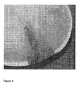
Fig 2 shows a schematic view of the coated implant according to the invention inserted in the bone and cartilage surface of a joint. -
Fig 3 shows a photo of the coated implant according to the invention inserted in the bone and cartilage surface of a joint. - The present invention relates to a new medical implant for replacing or repairing damaged, diseased or injured cartilage in an articulating surface of a joint. The implant has a cartilage contact surface, intended to contact the cartilage in a joint, which is coated with a bioactive material capable of stimulating cartilage growth and regeneration. The implant alleviates problems discussed in the background, by promoting cartilage on-growth to the implant. By this feature the implant becomes more integrated with the cartilage surface, yielding a more stabilized interaction and firmer attachment between the implant and the cartilage. Thereby cartilage damage in the vicinity of the implant is decreased. Also the entering of joint fluid between the implant, cartilage and bone is reduced or prevented. In addition, a smoother transition between the cartilage and the implant may be obtained, leading to lesser wear on the opposing surface of the joint as the cartilage and the implant works as an integrated mechanical entity.
-
Fig. 1a shows an exemplifying embodiment of an implant 1 according to the present invention. The implant 1 comprises a contoured, substantially plate shapedimplant body 11 and an extendingpost 8 extending from theimplant body 11. Theimplant body 11 has anarticulate surface 3, configured to face the articulating part of the joint, and abone contact surface 6, configured to face the bone structure of the joint. Between these surfaces of the plate shapedbody 11 of the implant 1 there is acartilage contact surface 7, on the rim or border that connects the articulate and the bone contact surfaces. Thecartilage contact surface 7 is configured to face or contact the cartilage, and optionally also the bone, surrounding the implant when the implant is inserted in a joint such as a knee, toe, hip, elbow or shoulder. The cartilage contact surface is coated with a bioactive material, such as a hydroxyapatite coating. - The implant is placed in the joint after removal of the damaged cartilage and optionally, but preferably, formation of a recess in the bone under the cartilage damage, e.g. by reaming. The implant is secured in the bone first by primary attachment, by means of the extending
post 8 which fits in a drill hole in the bone. The implant is also secured by a long-term secondary fixation mechanism where cartilage and/or bone tissue is grown into and/or onto the parts of the implant coated with bioactive material. - The implant 1 comprises a contoured, substantially plate shaped
implant body 11. Theimplant body 11 has a thin, plate-like design, meaning that itscross-sectional distance 9 is larger or even substantially larger than its thickness 4, e.g. at least 1.5 times larger. The plate can vary in size and shape and may be adjusted to the size and shape of the damaged cartilage tissue and to the needs of particular treatment situations. For instance the cross-section of theimplant body 11 may have a circular or roughly circular, oval, triangular, square or irregular shape, preferably a shape without sharp edges. The size of the implant 1 may also vary. The surface area of theimplant body 11 varies in different realizations of the invention between 0.5 cm2 and 20 cm2, between 0,5 cm2 and 15 cm2, between 0,5 cm2 and 10 cm2 or between about 1-10 cm2, preferably between 0,5 cm2 and 5 cm2. In general, small implants are preferred since they have a smaller impact on the joint at the site of incision and are also more easily implanted which leads to smaller open surgical procedures. The primary factor for determining the size of the implant is however the nature of the lesion in the cartilage to be repaired. The thickness 4 of theimplant body 11 is between 1 mm and about 10 mm, preferably between about 2 mm and 5 mm. The thickness of theimplant body 11 should on the whole preferably match the thickness of the original cartilage layer, possibly also adapted to adjust for the recess in the bone, used for anchorage of the implant or formed as a part of the disease process. The articulate surface and the cartilage surrounding the implant have, because of the prepared precise fit of the implant in the implant site, corresponding heights. - The
implant body 11 has anarticulate surface 3 configured to face the articulating part of the joint. Thearticulate surface 3 comprises a biocompatible metal, metal alloy or ceramic. More specifically it can consist of any metal or metal alloy used for structural applications in the human or animal body, such as stainless steel, cobalt-based alloys, chrome-based alloys, titanium-based alloys, pure titanium, zirconium-based alloys, tantalum, niobium and precious metals and their alloys. If a ceramic is used as the biocompatible material, it can be a biocompatible ceramic such as aluminium oxide, silicon nitride or yttria-stabilized zirconia. Preferably thearticulate surface 3 comprises a cobalt chrome alloy (CoCr), pyrolytic carbon stainless steel, or a ceramic material. - It should also be understood that the
articulate surface 3 may also be further surface treated in order to e.g. achieve an even more durable surface or a surface with a lower friction coefficient. Such treatments may include, for example, polishing, micro machining, heat treatment, precipitation hardening or depositing a suitable surface coating. - The
implant body 11 has abone contact surface 6, configured to face or contact the bone structure of the joint. In one embodiment thebone contact surface 6 comprises a biocompatible metal, metal alloy or ceramic, such as any of the metals, metal alloys or ceramic described above for thearticulate surface 3. Preferably thebone contact surface 6 comprises a cobalt chrome alloy (CoCr) or stainless steel. - In one embodiment the
bone contact surface 6 comprises, or in one specific embodiment is coated with, a bioactive material. In an alternative embodiment of the invention the bone contact surface does not comprise a bioactive material and/or is uncoated. - The bioactive material of the bone contact surface, if present, preferably stimulates bone to grow into and/or onto the implant surface. Several bioactive materials that have a stimulating effect on bone growth are known and have been used to promote adherence between implants and bone. Examples of such prior art bioactive materials include bioactive glass, bioactive ceramics and biomolecules such as collagens, fibronectin, osteonectin and various growth factors, e.g. bone morphogenetic protein (BMP). A commonly used bioactive material in the field of implant technology is the bioactive ceramic hydroxyapatite (HA), chemical formula Ca10(PO4)6(OH)2. HA is the major mineral constituent of bone and is able to slowly bond with bone in vivo. Thus, HA coatings have been developed for medical implants to promote bone attachment. Other bioactive ceramics include calcium sulphate, calcium phosphate, calcium aluminates, calcium silicates, calcium carbonates or combinations thereof, or bioactive glass. Bioactive glasses, generally comprising SiO2, CaSiO3, P2O5, Na2O and/or CaO and possibly other metal oxides or fluorides, are able to stimulate bone growth faster than HA.
- The bioactive materials described above have an anabolic effect on the bone i.e. stimulates bone growth. The fixation of the implant can also be improved by decreasing the catabolic processes i.e. decrease the amount of bone resorption next to the implant. The bone contact surface 21 and/or the extending post can also be modified with bisphosphonates. Bisphosphonates are substances that inhibit the catabolic process of bone. One way to bind the bisphosphonate to the surface is by coating it with HA, which it readily binds to. The implant can also simply be immersed in a bisphosphonate solution or linked with some other biocompatible molecule e.g. carbodiimides, N-hydroxysuccinimide (NHS)-esters, fibrinogen, collagen etc.
- The bone contact surface may also be further modified with fluoro compounds to enhance the bioactivity of the surface.
- In one embodiment the
bone contact surface 6 is coated with a double coating. Such double coating may for instance comprise an inner coating comprising titanium (Ti). The second, outer coating, that is configured to contact the bone, is preferably a HA coating containing more than 95% HA or 95-99,5% HA, or a coating comprising tricalcium phosphate (TCP) in combination with HA. By this design even more long-term fixation of the implant is achieved, since bone in- or on-growth to the implant is further stimulated by the titanium, even if the more brittle and/or soluble HA and/or TCP would eventually shed or dissolve. - Between the
articulate surface 3 and thebone contact surface 6 of the plate shapedbody 11 there is acartilage contact surface 7 on the rim or border which connects the articulate and the bone contact surfaces. Thecartilage contact surface 7 is configured to face or contact the cartilage surrounding the implant and optionally also the bone underlying the cartilage layer when the implant is inserted in a joint for example in the knee. Thecartilage contact surface 7 is coated with a bioactive material, such as any of bioactive materials described above for thebone contact surface 6. Preferably the bioactive material is capable of stimulating cartilage growth, regeneration and attachment. The bioactive surface promotes adhesion of the implant to the surrounding cartilage surface. Such bioactive materials include hydroxyapatite (HA), titanium (Ti), bone morphogenetic protein (BMP) or beta tricalcium phosphate (TCP), separately or in combination. In a preferred embodiment the bioactive material of thecartilage contact surface 3 is hydroxyapatite (HA) and/or beta tricalcium phosphate (TCP). - In one embodiment the
cartilage contact surface 7 is coated with a double coating, such as described for thebone contact surface 6 above. Such double coating may for instance comprise an inner coating comprising titanium (Ti). The second, outer coating, that is configured to contact the bone, is preferably a HA coating containing more than 95% HA or 95-99,5% HA, or a coating comprising tricalcium phosphate (TCP), or a combination of HA and TCP. - Using a bioactive material such as hydroxyapatite as a coating on the
cartilage contact surface 7 of the implant has the effect that the implant, after insertion at the implant site with primary fixation, is fixated by a secondary fixation mechanism where the cartilage grows together with the bioactive coating of the implant, creating a smooth sealed surface without any holes or where joint fluid can pass. This would lead to an implant that stays in the right place and that is not prone to be undermined by joint fluids. Also, the smooth surface, where the implant and the surrounding cartilage may act as an integrated mechanical entity, reduces or prevents wear damage on the surface of the opposing side of the joint. - The height 4 of the
cartilage contact surface 7 corresponds to at least 75% of the thickness of the cartilage at the site of implant insertion in the joint. More preferably the height 4 of thecartilage contact surface 7 corresponds to the height of the cartilage surrounding the implant site plus the height of an area reamed out from the underlying bone in order to fit and fix the implant. The height 4 of thecartilage contact surface 7 may vary between said extremes. Typically the height 4 of thecartilage contact surface 7 is between 0,5 and 8 mm, preferably between 1 and 5 mm. - The bioactive coating on the
cartilage contact surface 7 is preferably provided all the way around thecartilage contact surface 7 on the rim of the plate shapedimplant body 11. The coating is intended to be in direct contact with the surrounding cartilage and bone of a joint once the implant is implanted in the cartilage of a joint, for example a knee. The coating covers 60-100%, more preferably 80-100% and most preferably 90-100% of thecartilage contacting surface 7. In another embodiment the surface is coated such that the height 4 all around the rim of theimplant body 11 is 80-100%, preferably 90-100% covered, counting from thebone contact surface 6 and upwards. In still another embodiment the coating covers most of thecartilage contact surface 7, except for an uncoated section 0,5-1 mm at the top of the height 4, adjacent to thearticulate surface 3. By keeping the section closest to the articulate surface uncoated shedding of the bioactive material onto the cartilage surface surrounding the implant is prevented/reduced, thereby reducing the risk of wear from the shed material onto the joint surfaces. - The coating technique used is thermal spraying; in particular, air plasma spraying is the method which is used for producing these hydroxyapatite coatings on the implant. Another alternative is Vacuum Plasma Spray coating (VPS). In a hydroxyapatite embodiment the coating contains more than 95% hydroxyapatite by XRD after heating of alternatively the coating or the hydroxyapatite coating contains 95-99.5% hydroxyapatite.
- The
implant body 11 may have one or several extendingposts 8 which extend from thebone contact surface 6. In order to promote an immediate attachment of the implant to the bone as it is implanted into the body, the extendingpost 8 is used for immediate, mechanical attachment, called primary fixation. The extendingpost 8 has a physical structure in the form of for example a cylinder or other shapes such as one or more of a small screw, peg, keel, barb or the like. Theimplant body 11 and the extending post(s) 8 may be manufactured as a single, integral piece or as separate pieces that are joined by some kind of attachment means, e.g. glue or by a threaded joint. - The primary fixation means 4 may comprise e.g. the metal, metal alloy or ceramic, as in the
articulate surface 3. - The extending
post 8 can in one aspect of the invention be coated with a bioactive material such as described for thebone contact surface 6 above. In another aspect of the invention the extending post is uncoated. - In one embodiment the extending
post 8 comprises uncoated titanium (Ti) and thecartilage contact surface 7 are coated with hydroxyapatite (HA) or a double coating with an inner coating comprising titanium (Ti) and an outer coating comprising HA, tricalcium phosphate (TCP), or a combination of HA and TCP. - An implant which does not have a coating on the extending
post 8, and thus lacks a secondary fixation of the extending post, is suitable for repairing a cartilage damage in for example a hip joint where a lot of pressure is applied on the placed implant and where there is a need for an implant which reduces the risk for tensions when the mechanical pressure is high. By avoiding coating of the extending post, the extending post is thus not attached to the bone; the mechanical forces are in this way not directed into the bone part through the extending post (which may lead to tensions in the bone structure). The mechanical forces are directed to the bone through the implant head only which reduces the risk for tensions in the bone on the implant site. - An implant according to the present invention may be manufactured in predetermined, standard shapes and sizes or be tailor made for specific patients. A variety of manufacturing processes are conceivable, including, casting, molding, sintering or turning/cutting a blank e.g. with laser etc.
- In one embodiment the implant according to the present invention the
articulate surface 3 may be formed in a way so that it substantially corresponds to the curvature of the articulating surface at the site of the diseased cartilage and such that it is adapted to a particular individual and its cartilage damage. Techniques for obtaining such 3D images, of either the cartilage or the underlying bone or both may also include X-rays, optical coherence tomography, SPECT, PET, MR and ultrasound imaging techniques. The 3D images are used for measuring the reconstruction of the bone and the thickness and/or curvature of the cartilage and for determining the position, size and contour of damaged cartilage or cartilage loss. - A technique for making these tailor made implants is selective laser sintering (SLS). SLS is an additive manufacturing technique that uses a high power laser (for example, a carbon dioxide laser) to fuse small particles of plastic, metal (Direct metal laser sintering), ceramic, or glass powders into a mass representing a desired 3-dimensional object. The laser selectively fuses powdered material by scanning cross-sections generated from a 3-D digital description of the part (for example from a CAD file or scan data) on the surface of a powder bed. After each cross-section is scanned, the powder bed is lowered by one layer thickness, a new layer of material is applied on top, and the process is repeated until the part is completed. Or, the 3D surfaces are formed with a high precision lathe, a machine in which work is rotated about a horizontal axis and shaped by a fixed tool. The 3D surfaces can also be reamed using the digital data.
- Implants 1 according to the invention were tested on adult sheep, approximately 1.5 years old;
- Defects in the medial femoral condyles in the knee of the sheep were created.
- Implants were inserted to replace the created defect areas in the medial femoral condyles.
- Implants were retrieved and checked by taking histological preparations from the implant site after 6 weeks and after 3 months from insertion. An exact series of equipment, able to cut through metal as well as bone, was used. En bloc samples were retrieved, showing a cross-section of the implantation site (see
figure 2 and3 ). Light microscopy revealed good integration of the implants to the bone. It was also observed that the surroundingcartilage 71 had reacted with close adherence to the HA containing surface of the implant. This suggests that HA attracts also cartilage and promotes a biological activity.
Claims (8)
- A medical implant (1) for cartilage repair at an articulating surface of a joint, comprising a contoured, substantially plate shaped, implant body (11) and at least one extending post (8), where said implant body has:a. an articulate surface (3) configured to face the articulating part of the joint;b. a bone contact surface (6) configured to face the bone structure of a joint, where the bone contact surface (6) is provided with the extending post (8), said articulate (3) and bone contact (6) surfaces facing mutually opposite directions; andc. a cartilage contact surface (7), connecting the articulate (3) and the bone contact (6) surfaces, which is configured to contact the cartilage surrounding the implant body (11) in a jointcharacterized in that
the articulate surface (3) substantially corresponds to the curvature of the articulating surface of the site of the diseased cartilage and the cartilage contact surface (7) has a coating substantially consisting of a bioactive material selected from hydroxyapatite (HA) or wherein the cartilage contact surface has a double coating, comprising an inner coating of titanium and a surface coating of hydroxyapatite
and wherein said implant (1) is not made of porous material. - The medical implant of any of the preceding claims, wherein said bioactive material is hydroxyapatite (HA).
- The medical implant according to any of the preceding claims, wherein said bone contact surface (6) is coated or partly coated with bioactive material.
- The medical implant according to any of the preceding claims wherein said extending post is coated or partly coated with bioactive material.
- The medical implant according to any of claims 3 or 4, wherein said bioactive material of the bone contact surface (6) and/or extending post (8) is any of hydroxyapatite (HA), titanium (Ti), bone morphogenetic protein (BMP), beta tricalcium phosphate (TCP), collagens, fibronectin, osteonectin, calcium sulphate, calcium phosphate, calcium aluminates, calcium silicates, calcium carbonates, bioactive glass or bisphosphonates, or combinations thereof.
- The medical implant according any of the preceding claims 1-3 and 5, wherein said extending post is not coated with bioactive material
- The medical implant according to any of the preceding claims wherein the coating of the cartilage contact surface (7) and/or bone contact surface (6) and/or extending post (8) consists of more than 95% hydroxyapatite according to XRD.
- The medical implant according to any of the preceding claims, wherein the bone contact surface has a double coating, comprising an inner coating of titanium and a surface coating of hydroxyapatite and/or tricalcium phosphate.
Priority Applications (6)
| Application Number | Priority Date | Filing Date | Title |
|---|---|---|---|
| EP10163721.3A EP2389901B8 (en) | 2010-05-24 | 2010-05-24 | An implant for cartilage repair |
| US13/699,090 US10470885B2 (en) | 2010-05-24 | 2011-05-24 | Implant for cartilage repair |
| PCT/EP2011/058484 WO2011147836A2 (en) | 2010-05-24 | 2011-05-24 | An implant for cartilage repair |
| JP2013511657A JP5397796B2 (en) | 2010-05-24 | 2011-05-24 | Cartilage treatment implant |
| US15/965,592 US20180243096A1 (en) | 2010-05-24 | 2018-04-27 | Implant for cartilage and/or bone repair |
| US16/676,583 US20200163771A1 (en) | 2010-05-24 | 2019-11-07 | Implant for cartilage repair |
Applications Claiming Priority (1)
| Application Number | Priority Date | Filing Date | Title |
|---|---|---|---|
| EP10163721.3A EP2389901B8 (en) | 2010-05-24 | 2010-05-24 | An implant for cartilage repair |
Publications (3)
| Publication Number | Publication Date |
|---|---|
| EP2389901A1 EP2389901A1 (en) | 2011-11-30 |
| EP2389901B1 true EP2389901B1 (en) | 2013-04-03 |
| EP2389901B8 EP2389901B8 (en) | 2013-05-15 |
Family
ID=42989216
Family Applications (1)
| Application Number | Title | Priority Date | Filing Date |
|---|---|---|---|
| EP10163721.3A Active EP2389901B8 (en) | 2010-05-24 | 2010-05-24 | An implant for cartilage repair |
Country Status (4)
| Country | Link |
|---|---|
| US (2) | US10470885B2 (en) |
| EP (1) | EP2389901B8 (en) |
| JP (1) | JP5397796B2 (en) |
| WO (1) | WO2011147836A2 (en) |
Families Citing this family (27)
| Publication number | Priority date | Publication date | Assignee | Title |
|---|---|---|---|---|
| US6712856B1 (en) * | 2000-03-17 | 2004-03-30 | Kinamed, Inc. | Custom replacement device for resurfacing a femur and method of making the same |
| EP2389901B8 (en) | 2010-05-24 | 2013-05-15 | Episurf IP Management AB | An implant for cartilage repair |
| US9498334B2 (en) * | 2012-03-27 | 2016-11-22 | DePuy Synthes Products, Inc. | Glenoid defect-filling component |
| CN103420681B (en) * | 2012-05-15 | 2015-12-16 | 中南大学 | The method utilizing selective laser and temperature controlling stove to realize double sintering to prepare artificial bone |
| DE102014211725A1 (en) * | 2013-06-18 | 2014-12-18 | Ceram Tec Gmbh | Ceramic components for replacement of joint surfaces |
| CN103394124B (en) * | 2013-08-01 | 2015-04-01 | 上海师范大学 | Preparation method for well-aligned rodlike hydroxylapatite coating |
| WO2016175967A1 (en) * | 2015-04-30 | 2016-11-03 | Encore Medical, L.P. | Soft tissue repair using a porous coating implant |
| CN108025106A (en) * | 2015-09-29 | 2018-05-11 | 陶瓷技术有限责任公司 | The ceramic layer of thermal spraying |
| US11526988B2 (en) | 2015-12-18 | 2022-12-13 | Episurf Ip-Management Ab | System and method for creating a decision support material indicating damage to an anatomical joint |
| EP3181050B1 (en) * | 2015-12-18 | 2020-02-12 | Episurf IP Management AB | System and method for creating a decision support material indicating damage to an anatomical joint |
| CN105534619A (en) * | 2016-01-28 | 2016-05-04 | 江苏奥康尼医疗科技发展有限公司 | Cartilage repair and compensation prosthesis |
| WO2017155956A1 (en) * | 2016-03-07 | 2017-09-14 | Ossio Ltd | Surface treated biocomposite material, medical implants comprising same and methods of treatment thereof |
| CA3035803A1 (en) * | 2016-09-08 | 2018-03-15 | Karl Leibinger Medizintechnik Gmbh & Co. Kg | Method for producing an implant using a calcium carbonate-containing composite powder comprising microstructured particles |
| WO2018046238A1 (en) * | 2016-09-08 | 2018-03-15 | Karl Leibinger Medizintechnik Gmbh & Co. Kg | Implant comprising a calcium salt-containing composite powder having microstructred particles |
| JP6759022B2 (en) * | 2016-09-09 | 2020-09-23 | テルモ株式会社 | Implant system |
| US20200061239A1 (en) * | 2016-09-21 | 2020-02-27 | Orthopaedic Innovation Centre Inc. | Antimicrobial articles produced by additive manufacturing |
| CN106693053A (en) * | 2016-12-23 | 2017-05-24 | 大连三生科技发展有限公司 | Implant with BMP-2 slow-release composite coating |
| US10537658B2 (en) | 2017-03-28 | 2020-01-21 | DePuy Synthes Products, Inc. | Orthopedic implant having a crystalline gallium-containing hydroxyapatite coating and methods for making the same |
| US10537661B2 (en) | 2017-03-28 | 2020-01-21 | DePuy Synthes Products, Inc. | Orthopedic implant having a crystalline calcium phosphate coating and methods for making the same |
| US11250561B2 (en) | 2017-06-16 | 2022-02-15 | Episurf Ip-Management Ab | Determination and visualization of damage to an anatomical joint |
| SE543241C2 (en) * | 2018-04-27 | 2020-10-27 | Episurf Ip Man Ab | An implant for cartilage and/or bone repair |
| CN108705092B (en) * | 2018-06-15 | 2021-06-01 | 淮阴工学院 | 3D printing in-situ rare earth doped titanium-based composite material active bone implant and forming method |
| CN109010925A (en) * | 2018-09-07 | 2018-12-18 | 王翀 | A kind of preparation method of photo-thermal chemotherapy bone renovating material and tissue engineering bracket |
| US11645749B2 (en) | 2018-12-14 | 2023-05-09 | Episurf Ip-Management Ab | Determination and visualization of damage to an anatomical joint |
| US11090412B2 (en) | 2018-12-21 | 2021-08-17 | Zavation Medical Products Llc | Bone repair composition and kit |
| US11621086B2 (en) | 2020-06-04 | 2023-04-04 | Episurf Ip-Management Ab | Customization of individualized implant |
| CN112245069B (en) * | 2020-11-20 | 2022-06-14 | 北京爱康宜诚医疗器材有限公司 | Cartilage prosthesis |
Family Cites Families (65)
| Publication number | Priority date | Publication date | Assignee | Title |
|---|---|---|---|---|
| GB8620937D0 (en) * | 1986-08-29 | 1986-10-08 | Shepperd J A N | Spinal implant |
| SE9001009L (en) | 1990-03-21 | 1991-09-22 | Ytbolaget I Uppsala Ab | PROCEDURE SHOULD CREATE A HAIR AND Wear-Resistant Layer With Good Adhesion To Titanium Or Titanium Regulations And Products, Manufactured According To The Procedure |
| US5702448A (en) | 1990-09-17 | 1997-12-30 | Buechel; Frederick F. | Prosthesis with biologically inert wear resistant surface |
| JP2883214B2 (en) * | 1990-12-28 | 1999-04-19 | 京セラ株式会社 | Biological implant material and its manufacturing method |
| US6001104A (en) | 1991-12-03 | 1999-12-14 | Boston Scientific Technology, Inc. | Bone anchor implantation device |
| US5766221A (en) | 1991-12-03 | 1998-06-16 | Boston Scientific Technology, Inc. | Bone anchor implantation device |
| US5370700A (en) | 1993-02-19 | 1994-12-06 | Sarkisian; James S. | Prosthetic knee joint |
| JPH07236802A (en) * | 1994-02-28 | 1995-09-12 | Yoshikawa Enbi Kogyosho:Kk | Sewage treatment aid |
| JPH08173523A (en) * | 1994-12-20 | 1996-07-09 | Nikon Corp | Inbone implant and its manufacture |
| WO1997016137A1 (en) | 1995-10-31 | 1997-05-09 | Sarkisian James S | Prosthetic joint and method of manufacture |
| US7468075B2 (en) * | 2001-05-25 | 2008-12-23 | Conformis, Inc. | Methods and compositions for articular repair |
| US6296641B2 (en) * | 1998-04-03 | 2001-10-02 | Bionx Implants Oy | Anatomical fixation implant |
| US6261322B1 (en) * | 1998-05-14 | 2001-07-17 | Hayes Medical, Inc. | Implant with composite coating |
| US6395011B1 (en) | 1998-07-17 | 2002-05-28 | Johnson & Johnson | Method and apparatus for harvesting and implanting bone plugs |
| CA2393776C (en) | 1999-12-15 | 2009-02-10 | Sulzer Orthopedics Ltd. | Preparation for repairing cartilage defects or cartilage/bone defects in human or animal joints |
| US6626945B2 (en) | 2000-03-14 | 2003-09-30 | Chondrosite, Llc | Cartilage repair plug |
| AU5932701A (en) * | 2000-05-01 | 2001-11-12 | Std Mfg Inc | System and method for joint resurface repair |
| US7678151B2 (en) | 2000-05-01 | 2010-03-16 | Ek Steven W | System and method for joint resurface repair |
| EP2314257B9 (en) * | 2000-05-01 | 2013-02-27 | ArthroSurface, Inc. | System for joint resurface repair |
| US6488033B1 (en) | 2000-05-15 | 2002-12-03 | Cryolife, Inc. | Osteochondral transplant techniques |
| JP2002065709A (en) * | 2000-08-23 | 2002-03-05 | Tokyo Bio Ceramics Kenkyusho:Kk | Fixture of tooth or bone |
| CA2442855A1 (en) * | 2001-04-12 | 2002-10-24 | Therics, Inc. | Method and apparatus for engineered regenerative biostructures |
| US6626950B2 (en) * | 2001-06-28 | 2003-09-30 | Ethicon, Inc. | Composite scaffold with post anchor for the repair and regeneration of tissue |
| US6626667B2 (en) | 2002-01-16 | 2003-09-30 | Harold I. Sussman | Implant guide arrangement |
| US20040002766A1 (en) | 2002-06-27 | 2004-01-01 | Gordon Hunter | Prosthetic devices having diffusion-hardened surfaces and bioceramic coatings |
| FR2858209B1 (en) * | 2003-07-30 | 2006-06-02 | Depuy France | ACETABULAR IMPLANT AND METHOD OF MANUFACTURING THE IMPLANT |
| US20050049710A1 (en) | 2003-08-28 | 2005-03-03 | O'driscoll Shawn W. | Prosthesis for partial replacement of an articulating surface on bone |
| JP4315789B2 (en) * | 2003-11-28 | 2009-08-19 | オリンパス株式会社 | Bone filling material |
| US20050137600A1 (en) | 2003-12-23 | 2005-06-23 | Jacobs Andrew M. | Articular cartilage repair implant delivery device and method of use |
| EP1703867B1 (en) | 2004-01-12 | 2012-03-07 | Depuy Products, Inc. | Systems for compartmental replacement in a knee |
| GB2429164B (en) | 2004-03-11 | 2008-12-24 | Acumed Llc | Systems for bone replacement |
| WO2006060416A2 (en) | 2004-11-30 | 2006-06-08 | Osteobiologics, Inc. | Implants and delivery system for treating defects in articulating surfaces |
| US7160331B2 (en) | 2004-12-01 | 2007-01-09 | Mayo Foundation For Medical Research And Education | Sigmoid notch implant |
| US8172886B2 (en) | 2004-12-14 | 2012-05-08 | Depuy Products, Inc. | Bone plate with pre-assembled drill guide tips |
| US8828080B2 (en) | 2005-02-22 | 2014-09-09 | Barry M. Fell | Method and system for knee joint repair |
| JP2008531127A (en) | 2005-02-22 | 2008-08-14 | アースロサーフィス・インコーポレーテッド | Joint surface implant |
| DE102005010988A1 (en) | 2005-03-03 | 2006-09-14 | Karl Storz Gmbh & Co. Kg | Medical instrument for autologous chondrocyte transplantation |
| DE102005014623A1 (en) * | 2005-03-23 | 2006-09-28 | Aesculap Ag & Co. Kg | Surgical system for preparing an implant and method for preparing an implant |
| WO2006127486A2 (en) | 2005-05-20 | 2006-11-30 | Smith & Nephew, Inc. | Patello-femoral joint implant and instrumentation |
| US20070021838A1 (en) | 2005-07-22 | 2007-01-25 | Dugas Jeffrey R | Site specific minimally invasive joint implants |
| EP1981409B1 (en) | 2006-02-06 | 2017-01-11 | ConforMIS, Inc. | Patient selectable joint arthroplasty devices and surgical tools |
| US8473305B2 (en) | 2007-04-17 | 2013-06-25 | Biomet Manufacturing Corp. | Method and apparatus for manufacturing an implant |
| US20080257363A1 (en) | 2007-04-17 | 2008-10-23 | Biomet Manufacturing Corp. | Method And Apparatus For Manufacturing An Implant |
| US8858561B2 (en) | 2006-06-09 | 2014-10-14 | Blomet Manufacturing, LLC | Patient-specific alignment guide |
| US8070752B2 (en) | 2006-02-27 | 2011-12-06 | Biomet Manufacturing Corp. | Patient specific alignment guide and inter-operative adjustment |
| JP2007236802A (en) * | 2006-03-10 | 2007-09-20 | Takiron Co Ltd | Material for implant inclination |
| US20100168868A1 (en) * | 2006-11-30 | 2010-07-01 | Nihon University | Layered gradient material for biological use and method for producing the same |
| JP2008188400A (en) | 2007-02-06 | 2008-08-21 | Takehito Hananouchi | Artificial hip joint replacement assisting auxiliary member, and manufacturing method |
| CA2677316A1 (en) | 2007-02-06 | 2008-08-14 | Arthrosurface Inc. | System and method for joint resurface repair |
| EP2114312B1 (en) | 2007-02-14 | 2014-01-08 | ConforMIS, Inc. | Method for manufacture of an implant device |
| US8998918B2 (en) | 2008-02-12 | 2015-04-07 | Amir Jamali | Device and method for allograft and tissue engineered osteochondral graft surface matching, preparation, and implantation |
| GB0803514D0 (en) | 2008-02-27 | 2008-04-02 | Depuy Int Ltd | Customised surgical apparatus |
| WO2009108591A1 (en) * | 2008-02-28 | 2009-09-03 | Schwartz Biomedical, Llc | Partial joint resurfacing implant, instrumentation, and method |
| US8682052B2 (en) | 2008-03-05 | 2014-03-25 | Conformis, Inc. | Implants for altering wear patterns of articular surfaces |
| US8043375B2 (en) * | 2008-03-06 | 2011-10-25 | MoiRai Orthopaedic, LLC | Cartilage implants |
| EP2116210B1 (en) | 2008-05-06 | 2012-04-25 | Episurf Medical AB | Knee implant |
| US8556972B2 (en) | 2009-04-02 | 2013-10-15 | Sevika Holding AG | Monolithic orthopedic implant with an articular finished surface |
| US20100256758A1 (en) | 2009-04-02 | 2010-10-07 | Synvasive Technology, Inc. | Monolithic orthopedic implant with an articular finished surface |
| EP2389905B1 (en) | 2010-05-24 | 2012-05-23 | Episurf Medical AB | Method of designing a surgical kit for cartilage repair in a joint |
| EP2389901B8 (en) | 2010-05-24 | 2013-05-15 | Episurf IP Management AB | An implant for cartilage repair |
| EP2389904B1 (en) | 2010-05-24 | 2013-07-24 | Episurf IP Management AB | Surgical kit for cartilage repair comprising implant and a set of tools |
| EP2389899B1 (en) | 2010-05-24 | 2015-04-29 | Episurf IP Management AB | Method of manufacturing a surgical kit for cartilage repair in a joint |
| US20170100253A1 (en) | 2011-09-02 | 2017-04-13 | Episurf Ip-Management Ab | Design of an implant for cartilage repair |
| BR112014005660A2 (en) | 2011-09-15 | 2017-04-04 | Amedica Corp | coated implants and related methods |
| CA2870017A1 (en) | 2012-04-13 | 2013-10-17 | Conformis, Inc. | Devices and methods for additive manufacturing of implant components |
-
2010
- 2010-05-24 EP EP10163721.3A patent/EP2389901B8/en active Active
-
2011
- 2011-05-24 US US13/699,090 patent/US10470885B2/en active Active
- 2011-05-24 JP JP2013511657A patent/JP5397796B2/en active Active
- 2011-05-24 WO PCT/EP2011/058484 patent/WO2011147836A2/en active Application Filing
-
2019
- 2019-11-07 US US16/676,583 patent/US20200163771A1/en not_active Abandoned
Also Published As
| Publication number | Publication date |
|---|---|
| WO2011147836A2 (en) | 2011-12-01 |
| EP2389901B8 (en) | 2013-05-15 |
| US10470885B2 (en) | 2019-11-12 |
| WO2011147836A3 (en) | 2012-04-12 |
| JP2013531515A (en) | 2013-08-08 |
| EP2389901A1 (en) | 2011-11-30 |
| JP5397796B2 (en) | 2014-01-22 |
| US20130110252A1 (en) | 2013-05-02 |
| US20200163771A1 (en) | 2020-05-28 |
Similar Documents
| Publication | Publication Date | Title |
|---|---|---|
| US20200163771A1 (en) | Implant for cartilage repair | |
| US11529237B2 (en) | Method of manufacturing an implant and an implant with two coatings | |
| ZWEYMÜLLER et al. | Biologic fixation of a press-fit titanium hip joint endoprosthesis. | |
| Geesink et al. | Chemical implant fixation using hydroxyl-apatite coatings | |
| US20180243096A1 (en) | Implant for cartilage and/or bone repair | |
| EP1527757B1 (en) | Manufacturing process for a prosthetic implant | |
| US10966733B2 (en) | Implant specific drill bit in surgical kit for cartilage repair | |
| US20170100253A1 (en) | Design of an implant for cartilage repair | |
| US8657822B2 (en) | Surgical kit for cartilage repair comprising implant and a set of tools | |
| AU2012300837A1 (en) | Surgical kit for cartilage repair | |
| KR20120112670A (en) | Prosthesis | |
| US11000387B2 (en) | Implant for cartilage repair | |
| Daugaard | The influence of parathyroid hormone treatment on implant fixation | |
| WO2012003037A9 (en) | Convex concave implant | |
| Thomas et al. | Total hip arthroplasty | |
| Uklejewski et al. | Prototype of a Biomimetic Multi-Spiked Connecting Scaffold for a New Generation of Resurfacing Endoprostheses | |
| EP4241738A1 (en) | Non-polygonal porous structure | |
| EP1178765B1 (en) | Cementless total replacement of the human hip joint | |
| Park et al. | Hard tissue replacement II: joints and teeth | |
| US10765523B2 (en) | Prosthesis component and method for the production thereof | |
| Homsy | Tissue-ingrowth implant fixation by a soft porous coating | |
| Smith | Variable Density Ceramics Produced by Three Dimensional Printing | |
| Iwata et al. | Characterization and Biological Application of Hydroxyapatite-Glass-Titanium (HA-G-Ti) Functional Gradient Composite Material | |
| YAMAMURO et al. | and YASUTAKA MATSUDA | |
| Femoral et al. | HISTORICAL CONTEXT 989 OPTIMUM DESIGN CHARACTERISTICS OF AN EXTENSIVELY POROUS-COATED STEM 990 LABORATORY INVESTIGATION OF EXTENSIVELY COATED STEMS 990 |
Legal Events
| Date | Code | Title | Description |
|---|---|---|---|
| AK | Designated contracting states |
Kind code of ref document: A1 Designated state(s): AL AT BE BG CH CY CZ DE DK EE ES FI FR GB GR HR HU IE IS IT LI LT LU LV MC MK MT NL NO PL PT RO SE SI SK SM TR |
|
| AX | Request for extension of the european patent |
Extension state: BA ME RS |
|
| PUAI | Public reference made under article 153(3) epc to a published international application that has entered the european phase |
Free format text: ORIGINAL CODE: 0009012 |
|
| 17P | Request for examination filed |
Effective date: 20120126 |
|
| 17Q | First examination report despatched |
Effective date: 20120423 |
|
| RAP1 | Party data changed (applicant data changed or rights of an application transferred) |
Owner name: EPISURF MEDICAL AB |
|
| GRAP | Despatch of communication of intention to grant a patent |
Free format text: ORIGINAL CODE: EPIDOSNIGR1 |
|
| GRAS | Grant fee paid |
Free format text: ORIGINAL CODE: EPIDOSNIGR3 |
|
| GRAA | (expected) grant |
Free format text: ORIGINAL CODE: 0009210 |
|
| RIN1 | Information on inventor provided before grant (corrected) |
Inventor name: RYD, LEIF Inventor name: BAKE, NINA |
|
| AK | Designated contracting states |
Kind code of ref document: B1 Designated state(s): AL AT BE BG CH CY CZ DE DK EE ES FI FR GB GR HR HU IE IS IT LI LT LU LV MC MK MT NL NO PL PT RO SE SI SK SM TR |
|
| REG | Reference to a national code |
Ref country code: GB Ref legal event code: FG4D |
|
| REG | Reference to a national code |
Ref country code: AT Ref legal event code: REF Ref document number: 604223 Country of ref document: AT Kind code of ref document: T Effective date: 20130415 Ref country code: CH Ref legal event code: EP |
|
| RAP2 | Party data changed (patent owner data changed or rights of a patent transferred) |
Owner name: EPISURF IP MANAGEMENT AB |
|
| REG | Reference to a national code |
Ref country code: IE Ref legal event code: FG4D |
|
| REG | Reference to a national code |
Ref country code: DE Ref legal event code: R096 Ref document number: 602010005860 Country of ref document: DE Effective date: 20130529 |
|
| REG | Reference to a national code |
Ref country code: SE Ref legal event code: TRGR |
|
| REG | Reference to a national code |
Ref country code: AT Ref legal event code: MK05 Ref document number: 604223 Country of ref document: AT Kind code of ref document: T Effective date: 20130403 |
|
| PG25 | Lapsed in a contracting state [announced via postgrant information from national office to epo] |
Ref country code: SI Free format text: LAPSE BECAUSE OF FAILURE TO SUBMIT A TRANSLATION OF THE DESCRIPTION OR TO PAY THE FEE WITHIN THE PRESCRIBED TIME-LIMIT Effective date: 20130403 |
|
| REG | Reference to a national code |
Ref country code: NL Ref legal event code: VDEP Effective date: 20130403 |
|
| REG | Reference to a national code |
Ref country code: LT Ref legal event code: MG4D |
|
| PG25 | Lapsed in a contracting state [announced via postgrant information from national office to epo] |
Ref country code: LT Free format text: LAPSE BECAUSE OF FAILURE TO SUBMIT A TRANSLATION OF THE DESCRIPTION OR TO PAY THE FEE WITHIN THE PRESCRIBED TIME-LIMIT Effective date: 20130403 Ref country code: PT Free format text: LAPSE BECAUSE OF FAILURE TO SUBMIT A TRANSLATION OF THE DESCRIPTION OR TO PAY THE FEE WITHIN THE PRESCRIBED TIME-LIMIT Effective date: 20130805 Ref country code: NO Free format text: LAPSE BECAUSE OF FAILURE TO SUBMIT A TRANSLATION OF THE DESCRIPTION OR TO PAY THE FEE WITHIN THE PRESCRIBED TIME-LIMIT Effective date: 20130703 Ref country code: ES Free format text: LAPSE BECAUSE OF FAILURE TO SUBMIT A TRANSLATION OF THE DESCRIPTION OR TO PAY THE FEE WITHIN THE PRESCRIBED TIME-LIMIT Effective date: 20130714 Ref country code: BE Free format text: LAPSE BECAUSE OF FAILURE TO SUBMIT A TRANSLATION OF THE DESCRIPTION OR TO PAY THE FEE WITHIN THE PRESCRIBED TIME-LIMIT Effective date: 20130403 Ref country code: AT Free format text: LAPSE BECAUSE OF FAILURE TO SUBMIT A TRANSLATION OF THE DESCRIPTION OR TO PAY THE FEE WITHIN THE PRESCRIBED TIME-LIMIT Effective date: 20130403 Ref country code: IS Free format text: LAPSE BECAUSE OF FAILURE TO SUBMIT A TRANSLATION OF THE DESCRIPTION OR TO PAY THE FEE WITHIN THE PRESCRIBED TIME-LIMIT Effective date: 20130803 Ref country code: FI Free format text: LAPSE BECAUSE OF FAILURE TO SUBMIT A TRANSLATION OF THE DESCRIPTION OR TO PAY THE FEE WITHIN THE PRESCRIBED TIME-LIMIT Effective date: 20130403 Ref country code: GR Free format text: LAPSE BECAUSE OF FAILURE TO SUBMIT A TRANSLATION OF THE DESCRIPTION OR TO PAY THE FEE WITHIN THE PRESCRIBED TIME-LIMIT Effective date: 20130704 Ref country code: NL Free format text: LAPSE BECAUSE OF FAILURE TO SUBMIT A TRANSLATION OF THE DESCRIPTION OR TO PAY THE FEE WITHIN THE PRESCRIBED TIME-LIMIT Effective date: 20130403 |
|
| PG25 | Lapsed in a contracting state [announced via postgrant information from national office to epo] |
Ref country code: CY Free format text: LAPSE BECAUSE OF FAILURE TO SUBMIT A TRANSLATION OF THE DESCRIPTION OR TO PAY THE FEE WITHIN THE PRESCRIBED TIME-LIMIT Effective date: 20130403 Ref country code: HR Free format text: LAPSE BECAUSE OF FAILURE TO SUBMIT A TRANSLATION OF THE DESCRIPTION OR TO PAY THE FEE WITHIN THE PRESCRIBED TIME-LIMIT Effective date: 20130403 Ref country code: PL Free format text: LAPSE BECAUSE OF FAILURE TO SUBMIT A TRANSLATION OF THE DESCRIPTION OR TO PAY THE FEE WITHIN THE PRESCRIBED TIME-LIMIT Effective date: 20130403 Ref country code: BG Free format text: LAPSE BECAUSE OF FAILURE TO SUBMIT A TRANSLATION OF THE DESCRIPTION OR TO PAY THE FEE WITHIN THE PRESCRIBED TIME-LIMIT Effective date: 20130703 Ref country code: LV Free format text: LAPSE BECAUSE OF FAILURE TO SUBMIT A TRANSLATION OF THE DESCRIPTION OR TO PAY THE FEE WITHIN THE PRESCRIBED TIME-LIMIT Effective date: 20130403 |
|
| PG25 | Lapsed in a contracting state [announced via postgrant information from national office to epo] |
Ref country code: SK Free format text: LAPSE BECAUSE OF FAILURE TO SUBMIT A TRANSLATION OF THE DESCRIPTION OR TO PAY THE FEE WITHIN THE PRESCRIBED TIME-LIMIT Effective date: 20130403 Ref country code: DK Free format text: LAPSE BECAUSE OF FAILURE TO SUBMIT A TRANSLATION OF THE DESCRIPTION OR TO PAY THE FEE WITHIN THE PRESCRIBED TIME-LIMIT Effective date: 20130403 Ref country code: EE Free format text: LAPSE BECAUSE OF FAILURE TO SUBMIT A TRANSLATION OF THE DESCRIPTION OR TO PAY THE FEE WITHIN THE PRESCRIBED TIME-LIMIT Effective date: 20130403 Ref country code: CZ Free format text: LAPSE BECAUSE OF FAILURE TO SUBMIT A TRANSLATION OF THE DESCRIPTION OR TO PAY THE FEE WITHIN THE PRESCRIBED TIME-LIMIT Effective date: 20130403 Ref country code: MC Free format text: LAPSE BECAUSE OF FAILURE TO SUBMIT A TRANSLATION OF THE DESCRIPTION OR TO PAY THE FEE WITHIN THE PRESCRIBED TIME-LIMIT Effective date: 20130403 |
|
| PLBE | No opposition filed within time limit |
Free format text: ORIGINAL CODE: 0009261 |
|
| STAA | Information on the status of an ep patent application or granted ep patent |
Free format text: STATUS: NO OPPOSITION FILED WITHIN TIME LIMIT |
|
| REG | Reference to a national code |
Ref country code: IE Ref legal event code: MM4A |
|
| PG25 | Lapsed in a contracting state [announced via postgrant information from national office to epo] |
Ref country code: RO Free format text: LAPSE BECAUSE OF FAILURE TO SUBMIT A TRANSLATION OF THE DESCRIPTION OR TO PAY THE FEE WITHIN THE PRESCRIBED TIME-LIMIT Effective date: 20130403 |
|
| 26N | No opposition filed |
Effective date: 20140106 |
|
| REG | Reference to a national code |
Ref country code: DE Ref legal event code: R097 Ref document number: 602010005860 Country of ref document: DE Effective date: 20140106 |
|
| PG25 | Lapsed in a contracting state [announced via postgrant information from national office to epo] |
Ref country code: IE Free format text: LAPSE BECAUSE OF NON-PAYMENT OF DUE FEES Effective date: 20130524 |
|
| PG25 | Lapsed in a contracting state [announced via postgrant information from national office to epo] |
Ref country code: MT Free format text: LAPSE BECAUSE OF FAILURE TO SUBMIT A TRANSLATION OF THE DESCRIPTION OR TO PAY THE FEE WITHIN THE PRESCRIBED TIME-LIMIT Effective date: 20130403 |
|
| PG25 | Lapsed in a contracting state [announced via postgrant information from national office to epo] |
Ref country code: SM Free format text: LAPSE BECAUSE OF FAILURE TO SUBMIT A TRANSLATION OF THE DESCRIPTION OR TO PAY THE FEE WITHIN THE PRESCRIBED TIME-LIMIT Effective date: 20130403 |
|
| PG25 | Lapsed in a contracting state [announced via postgrant information from national office to epo] |
Ref country code: TR Free format text: LAPSE BECAUSE OF FAILURE TO SUBMIT A TRANSLATION OF THE DESCRIPTION OR TO PAY THE FEE WITHIN THE PRESCRIBED TIME-LIMIT Effective date: 20130403 |
|
| PG25 | Lapsed in a contracting state [announced via postgrant information from national office to epo] |
Ref country code: LU Free format text: LAPSE BECAUSE OF NON-PAYMENT OF DUE FEES Effective date: 20130524 Ref country code: MK Free format text: LAPSE BECAUSE OF FAILURE TO SUBMIT A TRANSLATION OF THE DESCRIPTION OR TO PAY THE FEE WITHIN THE PRESCRIBED TIME-LIMIT Effective date: 20130403 Ref country code: HU Free format text: LAPSE BECAUSE OF FAILURE TO SUBMIT A TRANSLATION OF THE DESCRIPTION OR TO PAY THE FEE WITHIN THE PRESCRIBED TIME-LIMIT; INVALID AB INITIO Effective date: 20100524 |
|
| REG | Reference to a national code |
Ref country code: FR Ref legal event code: PLFP Year of fee payment: 7 |
|
| REG | Reference to a national code |
Ref country code: FR Ref legal event code: PLFP Year of fee payment: 8 |
|
| REG | Reference to a national code |
Ref country code: FR Ref legal event code: PLFP Year of fee payment: 9 |
|
| PG25 | Lapsed in a contracting state [announced via postgrant information from national office to epo] |
Ref country code: AL Free format text: LAPSE BECAUSE OF FAILURE TO SUBMIT A TRANSLATION OF THE DESCRIPTION OR TO PAY THE FEE WITHIN THE PRESCRIBED TIME-LIMIT Effective date: 20130403 |
|
| PGFP | Annual fee paid to national office [announced via postgrant information from national office to epo] |
Ref country code: IT Payment date: 20230524 Year of fee payment: 14 Ref country code: FR Payment date: 20230516 Year of fee payment: 14 Ref country code: DE Payment date: 20230524 Year of fee payment: 14 Ref country code: CH Payment date: 20230602 Year of fee payment: 14 |
|
| PGFP | Annual fee paid to national office [announced via postgrant information from national office to epo] |
Ref country code: SE Payment date: 20230516 Year of fee payment: 14 |
|
| PGFP | Annual fee paid to national office [announced via postgrant information from national office to epo] |
Ref country code: GB Payment date: 20230523 Year of fee payment: 14 |