EP2389837B1 - Einstellungsvorrichtung mit elastischer Spannung für eine Schiebeanordnung - Google Patents
Einstellungsvorrichtung mit elastischer Spannung für eine Schiebeanordnung Download PDFInfo
- Publication number
- EP2389837B1 EP2389837B1 EP10163780.9A EP10163780A EP2389837B1 EP 2389837 B1 EP2389837 B1 EP 2389837B1 EP 10163780 A EP10163780 A EP 10163780A EP 2389837 B1 EP2389837 B1 EP 2389837B1
- Authority
- EP
- European Patent Office
- Prior art keywords
- rail
- elastic force
- adjustment
- fixing member
- elastic
- Prior art date
- Legal status (The legal status is an assumption and is not a legal conclusion. Google has not performed a legal analysis and makes no representation as to the accuracy of the status listed.)
- Active
Links
Images


Classifications
-
- A—HUMAN NECESSITIES
- A47—FURNITURE; DOMESTIC ARTICLES OR APPLIANCES; COFFEE MILLS; SPICE MILLS; SUCTION CLEANERS IN GENERAL
- A47B—TABLES; DESKS; OFFICE FURNITURE; CABINETS; DRAWERS; GENERAL DETAILS OF FURNITURE
- A47B88/00—Drawers for tables, cabinets or like furniture; Guides for drawers
- A47B88/40—Sliding drawers; Slides or guides therefor
- A47B88/453—Actuated drawers
- A47B88/46—Actuated drawers operated by mechanically-stored energy, e.g. by springs
- A47B88/463—Actuated drawers operated by mechanically-stored energy, e.g. by springs self-opening
Definitions
- the present invention relates to an elastic force adjustment device, and more particularly, to an elastic force adjustment device for adjusting the elastic force to control the distance that the rails travel in response to the load of the rails.
- U.S. Patent No. 7,374,261 discloses a push-open type slide structure comprises a top fastener and a locking device between an outer slide rail and a pull rod.
- the loading plate is extended from one side of the center portion of the main body.
- Two pillars are extended from both sides of the main body.
- a positioning fastener is coupled with the loading plate.
- a hook is mounted on the inner edge of the loading plate.
- a guide pillar is mounted on the rear end of the loading plate. The hook is inserted into the action trench of the main body and coupled with the elastic device.
- the locking device has a connection part for coupling with a guide part and a shaft holder.
- the push-open type slide structure is lockable or unlockable by pivotal rotation between the loading plate and the locking device. As a result, the push-open type slide structure can be controlled easily.
- the push-open type slide structure is operated by the stored force of the elastic device and the specification of the elastic device is chosen so as to have a fixed elastic force.
- the slide assembly When in use, the slide assembly is connected between the furniture part and the drawer so that when the drawer is pushed inward, the drawer opens automatically from the furniture part.
- the drawer has different loads, especially heavy objects, the load on the drawer applied to the rails cannot make the drawer to be opened to a desired position.
- the furniture include multiple drawers and different loads are received in the drawers, the drawers open to different positions which may be confused to the users.
- An elastic force adjustment device of the initially-mentioned type is already known from DE 20 2004 000 840 U1 .
- the inventor develops an elastic force adjustment device for the push-open type slide assembly so as to improve the shortcomings of the conventional push-open type slide assembly.
- the present invention intends to provide an elastic force adjustment device for the push-open type slide assembly, the adjustment device adjusts the stored elastic force to adjust the travel distance of the rails.
- the invention provides an elastic force adjustment device according to claim 1. Further embodiments of the invention are described in the dependent claims.
- the fixing member has a stop located between the first and second ends thereof.
- the movable member is movable between the second end of the fixing member and the stop.
- a buffering coat is mounted to the stop.
- the second rail includes a push member located corresponding to the movable member.
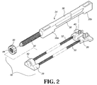
- the slide assembly comprises a first rail 12 and a second rail 14 which is slidably and longitudinally connected to the first rail 12.
- An elastic force adjustment device 16 of the present invention is installed to the first rail 12 so as to provide an adjustable and elastic force to the second rail 14 which is opened relative to the first rail 12.
- the first rail 12 includes a bottom board 18 and a sidewall 20 which extends perpendicularly from the bottom board 18.
- the second rail 14 includes a push member 22.
- the elastic force adjustment device 16 comprises a fixing member 24, a movable member 26, an adjustment frame 28, an adjustment member 30 and at least one elastic member 32, wherein the fixing member 24 is fixedly connected to the first rail 12 and includes a threaded rod 34 and a longitudinal body 36.
- the longitudinal body 36 has a first end 35a and a second end 35b which is located in opposite to the first end 35a.
- a longitudinal guiding portion 38 is located between the first and second ends 35a, 35b.
- the movable member 26 is slidably connected to the longitudinal guiding portion 38 of the fixing member 24 and movable along the longitudinal guiding portion 38.
- the movable member 26 includes a contact portion 40 which is located corresponding to the push member 22 of the second rail 14 so that the movable member 26 is moved with the movement of the push member 22 of the second rail 14 by the contact portion 40.
- the adjustment frame 28 has a mounting portion 42 connected to the threaded rod 34 of the fixing member 24.
- the adjustment member 30 has a threaded portion 44 threadedly connected to the threaded rod 34 of the fixing member 24.
- the at least one elastic member 32 (or two elastic members 32) has two ends which are respectively connected to the movable member 26 and the adjustment frame 28.
- Fig. 3 shows the second rail 14 is retracted relative to the first rail 12 and the push member 22 on the second rail 14 contacts the contact portion 40 of the movable member 26 of the elastic force adjustment device 16.
- the movable member 26 moves a pre-set distance along the longitudinal guiding portion 38 of the fixing member 24, so that the at least one elastic member 32 of the adjustment frame 28 and the movable member 26 are pulled so as to store an elastic force relative to the second rail 14.
- an engaging device (not shown) is connected between the first and second rails 12, 14 to position the second rail 14, relative to the retracted first rail 12 by the engaging device.
- the movable member 26 applied by the at least one elastic member 32 cannot push the second rail 14 via the push member 22.
- the adjustment frame 28 is moved by the adjustment member 30 and is set at the first position P1 on the threaded rod 34 of the fixing member 24.
- Fig. 4 shows that the adjustment member 30 of the elastic force adjustment device 16 is rotated on the threaded rod 34 of the fixing member 24 to contact and move the adjustment frame 28 from the first position P1 on the threaded rod 34 of the fixing member 24 to the second position P2, and the adjustment frame 28 is positioned at the second position P2.
- the relative distance between the movable member 26 and the adjustment frame 28 is adjusted, and the status of the at least one elastic member 32 of the adjustment frame 28 and the movable member 26 are adjusted. This is to say, the stored elastic force is adjusted.
- the movable member 26 applies the stored elastic force to the second rail 14, wherein the stored elastic force is formed according to the extension of the at least one elastic member 32.
- the elastic force from the at least one elastic member 32 is released and then applies to the contact portion 40 of the movable member 26 and moves the push member 22 of the second rail 14 so that the second rail 14 is opened to a desired position relative to the first rail 12.
- the fixing member 24 has a stop 46 located between the first and second ends 35a, 35b thereof.
- the stop 46 is located close to the first end 35a, and the movable member 26 is movable between the second end 35b of the fixing member 24 and the stop 46.
- a buffering coat 48 is mounted to the stop 46 so as to reduce the noise when the movable member 26 contacts the stop 46.
- the stop position of the movable member 26 applied by the elastic force of the at least one elastic member 32 can be controlled by the compressed length of the at least one elastic member 32.
- the adjustment member 30 and the adjustment frame 28 are adjusted to a third position on the threaded rod 34 of the fixing member 24. The third position allows the movable member 26 not to contact the first end 35a of the longitudinal guiding portion 38 of the fixing member 24 or the stop 46.
- the adjustment frame 28 further includes an urging member 50 wherein the adjustment member 30 is located and in contact between the urging member 50 and the mounting portion 42. By this arrangement, the adjustment member 30 and the adjustment frame 28 are moved back and forth together.
- the elastic force adjustment device for slide assembly allows the users to adjust the elastic force as needed. Especially when drawers are installed to the slide assembly and different weights of objects are received in the drawers, by the adjustment of the elastic force, the elastic force of each drawer can be properly adjusted so that the drawers can be opened to a desired position for convenience of accessing the objects in the drawers when the drawers are operated under the push-open mode.
Claims (4)
- Ein Schlitten mit einer Vorrichtung zur Verstellung der Spannkraft, wobei der Schlitten aus einer ersten Schiene (12) und aus einer zweiten Schiene (14) besteht; die zweite Schiene (14) gleitbar an der ersten Schiene (12) befestigt ist und die Vorrichtung zur Verstellung der Spannkraft aus den folgenden Komponenten umfassend:einem Befestigungsteil (24), das fest an der ersten Schiene (12) befestigt und mit einem länglichen Bauteil (36) gebildet ist; das längliche Bauteil (36) mit einem ersten Endteil (35a) und einem zweiten Endteil (35b) gegenüber dem ersten Endteil (35a) gebildet ist; ein längliches Führungsteil (38) zwischen dem ersten und zweiten Endteil (35a, 35b) gebildet istdadurch gekennzeichnet, dass:das Befestigungsteil (24) eine Gewindestange (34) aufweistein bewegliches Element (26) gleitbar am länglichen Führungsteil (38) des Befestigungsteils (24) befestigt isteine Verstelleinheit (28) mit einem Montageteil (42), das an der Gewindestange (34) des Befestigungsteils (24) befestigt und mit einem Andrückteil (50) gebildet ist;ein Verstellrad (30) mit einem Gewinde (44), in das die Gewindestange (34) des Befestigungsteils (24) eingeschraubt ist; das Verstellrad (30) zwischen dem Andrückteil (50) und dem Montageteil (42) angeordnet ist und mit diesen in Berührung kommt; mindestens eine Feder (32) zwei Enden aufweist, wobei eines dieser beiden Ende am beweglichen Element (26) und das andere an der Verstelleinheit (28) befestigt sind; eine Kraft durch die mindestens eine Feder (32) durch Rotieren des Verstellrades (30) an der Gewindestange (34) des Befestigungsteils (24) justiert wird.
- Die Vorrichtung nach Anspruch 1, wobei das Befestigungsteil (24) mit einem Anschlag (46) zwischen dem ersten und zweiten Endteil (35a, 35b) gebildet ist; das bewegliche Element (26) zwischen dem zweiten Ende (35b) des Befestigungsteils (24) und dem Anschlag (46) beweglich angeordnet ist.
- Die Vorrichtung nach Anspruch 2, weiter bestehend aus einem Pufferbelag (48), der am Anschlag (46) montiert ist.
- Die Vorrichtung nach Anspruch 1, wobei die zweite Schiene (14) mit einem Anschubteil (22) gebildet ist, das in Übereinstimmung mit dem beweglichen Element (26) angeordnet ist.
Priority Applications (2)
| Application Number | Priority Date | Filing Date | Title |
|---|---|---|---|
| EP10163780.9A EP2389837B1 (de) | 2010-05-25 | 2010-05-25 | Einstellungsvorrichtung mit elastischer Spannung für eine Schiebeanordnung |
| ES10163780.9T ES2577508T3 (es) | 2010-05-25 | 2010-05-25 | Dispositivo de regulación de energía elástica para ensamblaje corredizo |
Applications Claiming Priority (1)
| Application Number | Priority Date | Filing Date | Title |
|---|---|---|---|
| EP10163780.9A EP2389837B1 (de) | 2010-05-25 | 2010-05-25 | Einstellungsvorrichtung mit elastischer Spannung für eine Schiebeanordnung |
Publications (2)
| Publication Number | Publication Date |
|---|---|
| EP2389837A1 EP2389837A1 (de) | 2011-11-30 |
| EP2389837B1 true EP2389837B1 (de) | 2016-04-13 |
Family
ID=42830394
Family Applications (1)
| Application Number | Title | Priority Date | Filing Date |
|---|---|---|---|
| EP10163780.9A Active EP2389837B1 (de) | 2010-05-25 | 2010-05-25 | Einstellungsvorrichtung mit elastischer Spannung für eine Schiebeanordnung |
Country Status (2)
| Country | Link |
|---|---|
| EP (1) | EP2389837B1 (de) |
| ES (1) | ES2577508T3 (de) |
Families Citing this family (3)
| Publication number | Priority date | Publication date | Assignee | Title |
|---|---|---|---|---|
| AT511799B1 (de) | 2011-12-23 | 2013-03-15 | Blum Gmbh Julius | Anordnung zum bewegen eines bewegbaren möbelteils |
| CN104358780B (zh) * | 2014-11-28 | 2016-12-07 | 苏州中拓专利运营管理有限公司 | 一种滑动组合连接件 |
| DE202020101923U1 (de) * | 2020-03-11 | 2021-06-15 | Westermann Kg | In einem Schrankmöbel aufgenommener Auszug |
Family Cites Families (2)
| Publication number | Priority date | Publication date | Assignee | Title |
|---|---|---|---|---|
| DE202004000840U1 (de) * | 2004-01-20 | 2005-02-03 | Grass Gmbh | Schließvorrichtung, insbesondere für Möbelschubladen |
| US7374261B1 (en) | 2006-12-08 | 2008-05-20 | Dynaslide Corporation | Push-open type slide structure |
-
2010
- 2010-05-25 EP EP10163780.9A patent/EP2389837B1/de active Active
- 2010-05-25 ES ES10163780.9T patent/ES2577508T3/es active Active
Also Published As
| Publication number | Publication date |
|---|---|
| ES2577508T3 (es) | 2016-07-15 |
| EP2389837A1 (de) | 2011-11-30 |
Similar Documents
| Publication | Publication Date | Title |
|---|---|---|
| US8308251B2 (en) | Elastic force adjustment device for slide assembly | |
| US8172345B2 (en) | Self-moving device for movable furniture parts | |
| KR102012573B1 (ko) | 가구 구동 장치 | |
| US9416576B2 (en) | Mechanism for a sliding movement | |
| US8240789B2 (en) | Positioning device for slide assembly | |
| EP2438834B1 (de) | Verstärkungs- und Einstellungsvorrichtung für eine Schiebeanordnung | |
| US8801120B2 (en) | Self-opening and self-closing slide assembly | |
| EP1705330A1 (de) | Dämpfungsvorrichtung | |
| US20180087305A1 (en) | Ejection device for a movable furniture part | |
| US8764135B1 (en) | Linking mechanism | |
| EP2201863B1 (de) | Selbstbewegliche Vorrichtung für bewegliche Möbelteile | |
| US9364089B1 (en) | Self-closing slide rail assembly with deceleration mechanism | |
| US8561765B2 (en) | Damping device for movable furniture parts | |
| US9879460B2 (en) | Sliding door arrangement | |
| EP2389837B1 (de) | Einstellungsvorrichtung mit elastischer Spannung für eine Schiebeanordnung | |
| US20160270533A1 (en) | Drive device for a movable furniture part | |
| EP3094166B1 (de) | Gleitschienenanordnung | |
| KR20130041246A (ko) | 이젝터 장치 및 푸시 장치 | |
| US20160076293A1 (en) | System and device for soft closing | |
| US9936809B2 (en) | Cabinet assembly having a releasable support foot | |
| JP7030992B2 (ja) | 引出しガイド | |
| EP3025615B1 (de) | Selbstschließende Schienenanordnung mit Bremsmechanismus | |
| CA2704167C (en) | Elastic force adjustment device for slide assembly | |
| EP3251555B1 (de) | Ausziehführung für schubladen | |
| JP3161460U (ja) | スライドレールの弾力調整装置 |
Legal Events
| Date | Code | Title | Description |
|---|---|---|---|
| AK | Designated contracting states |
Kind code of ref document: A1 Designated state(s): AL AT BE BG CH CY CZ DE DK EE ES FI FR GB GR HR HU IE IS IT LI LT LU LV MC MK MT NL NO PL PT RO SE SI SK SM TR |
|
| AX | Request for extension of the european patent |
Extension state: BA ME RS |
|
| PUAI | Public reference made under article 153(3) epc to a published international application that has entered the european phase |
Free format text: ORIGINAL CODE: 0009012 |
|
| RIN1 | Information on inventor provided before grant (corrected) |
Inventor name: WANG, CHUN-CHIANG Inventor name: LIANG, HSIU-CHIANG Inventor name: CHEN, KEN-CHING |
|
| 17P | Request for examination filed |
Effective date: 20120530 |
|
| GRAP | Despatch of communication of intention to grant a patent |
Free format text: ORIGINAL CODE: EPIDOSNIGR1 |
|
| INTG | Intention to grant announced |
Effective date: 20151022 |
|
| GRAS | Grant fee paid |
Free format text: ORIGINAL CODE: EPIDOSNIGR3 |
|
| GRAA | (expected) grant |
Free format text: ORIGINAL CODE: 0009210 |
|
| AK | Designated contracting states |
Kind code of ref document: B1 Designated state(s): AL AT BE BG CH CY CZ DE DK EE ES FI FR GB GR HR HU IE IS IT LI LT LU LV MC MK MT NL NO PL PT RO SE SI SK SM TR |
|
| REG | Reference to a national code |
Ref country code: GB Ref legal event code: FG4D |
|
| REG | Reference to a national code |
Ref country code: AT Ref legal event code: REF Ref document number: 789119 Country of ref document: AT Kind code of ref document: T Effective date: 20160415 Ref country code: CH Ref legal event code: EP |
|
| REG | Reference to a national code |
Ref country code: IE Ref legal event code: FG4D |
|
| REG | Reference to a national code |
Ref country code: DE Ref legal event code: R096 Ref document number: 602010032183 Country of ref document: DE |
|
| REG | Reference to a national code |
Ref country code: ES Ref legal event code: FG2A Ref document number: 2577508 Country of ref document: ES Kind code of ref document: T3 Effective date: 20160715 |
|
| REG | Reference to a national code |
Ref country code: NL Ref legal event code: FP |
|
| REG | Reference to a national code |
Ref country code: LT Ref legal event code: MG4D |
|
| PG25 | Lapsed in a contracting state [announced via postgrant information from national office to epo] |
Ref country code: BE Free format text: LAPSE BECAUSE OF NON-PAYMENT OF DUE FEES Effective date: 20160531 |
|
| PG25 | Lapsed in a contracting state [announced via postgrant information from national office to epo] |
Ref country code: PL Free format text: LAPSE BECAUSE OF FAILURE TO SUBMIT A TRANSLATION OF THE DESCRIPTION OR TO PAY THE FEE WITHIN THE PRESCRIBED TIME-LIMIT Effective date: 20160413 Ref country code: FI Free format text: LAPSE BECAUSE OF FAILURE TO SUBMIT A TRANSLATION OF THE DESCRIPTION OR TO PAY THE FEE WITHIN THE PRESCRIBED TIME-LIMIT Effective date: 20160413 Ref country code: LT Free format text: LAPSE BECAUSE OF FAILURE TO SUBMIT A TRANSLATION OF THE DESCRIPTION OR TO PAY THE FEE WITHIN THE PRESCRIBED TIME-LIMIT Effective date: 20160413 Ref country code: NO Free format text: LAPSE BECAUSE OF FAILURE TO SUBMIT A TRANSLATION OF THE DESCRIPTION OR TO PAY THE FEE WITHIN THE PRESCRIBED TIME-LIMIT Effective date: 20160713 |
|
| REG | Reference to a national code |
Ref country code: DE Ref legal event code: R079 Ref document number: 602010032183 Country of ref document: DE Free format text: PREVIOUS MAIN CLASS: A47B0088040000 Ipc: A47B0088400000 |
|
| PG25 | Lapsed in a contracting state [announced via postgrant information from national office to epo] |
Ref country code: HR Free format text: LAPSE BECAUSE OF FAILURE TO SUBMIT A TRANSLATION OF THE DESCRIPTION OR TO PAY THE FEE WITHIN THE PRESCRIBED TIME-LIMIT Effective date: 20160413 Ref country code: PT Free format text: LAPSE BECAUSE OF FAILURE TO SUBMIT A TRANSLATION OF THE DESCRIPTION OR TO PAY THE FEE WITHIN THE PRESCRIBED TIME-LIMIT Effective date: 20160816 Ref country code: SE Free format text: LAPSE BECAUSE OF FAILURE TO SUBMIT A TRANSLATION OF THE DESCRIPTION OR TO PAY THE FEE WITHIN THE PRESCRIBED TIME-LIMIT Effective date: 20160413 Ref country code: LV Free format text: LAPSE BECAUSE OF FAILURE TO SUBMIT A TRANSLATION OF THE DESCRIPTION OR TO PAY THE FEE WITHIN THE PRESCRIBED TIME-LIMIT Effective date: 20160413 |
|
| PG25 | Lapsed in a contracting state [announced via postgrant information from national office to epo] |
Ref country code: BE Free format text: LAPSE BECAUSE OF FAILURE TO SUBMIT A TRANSLATION OF THE DESCRIPTION OR TO PAY THE FEE WITHIN THE PRESCRIBED TIME-LIMIT Effective date: 20160413 |
|
| REG | Reference to a national code |
Ref country code: CH Ref legal event code: PL |
|
| REG | Reference to a national code |
Ref country code: DE Ref legal event code: R097 Ref document number: 602010032183 Country of ref document: DE |
|
| PG25 | Lapsed in a contracting state [announced via postgrant information from national office to epo] |
Ref country code: SK Free format text: LAPSE BECAUSE OF FAILURE TO SUBMIT A TRANSLATION OF THE DESCRIPTION OR TO PAY THE FEE WITHIN THE PRESCRIBED TIME-LIMIT Effective date: 20160413 Ref country code: CH Free format text: LAPSE BECAUSE OF NON-PAYMENT OF DUE FEES Effective date: 20160531 Ref country code: RO Free format text: LAPSE BECAUSE OF FAILURE TO SUBMIT A TRANSLATION OF THE DESCRIPTION OR TO PAY THE FEE WITHIN THE PRESCRIBED TIME-LIMIT Effective date: 20160413 Ref country code: EE Free format text: LAPSE BECAUSE OF FAILURE TO SUBMIT A TRANSLATION OF THE DESCRIPTION OR TO PAY THE FEE WITHIN THE PRESCRIBED TIME-LIMIT Effective date: 20160413 Ref country code: MC Free format text: LAPSE BECAUSE OF FAILURE TO SUBMIT A TRANSLATION OF THE DESCRIPTION OR TO PAY THE FEE WITHIN THE PRESCRIBED TIME-LIMIT Effective date: 20160413 Ref country code: DK Free format text: LAPSE BECAUSE OF FAILURE TO SUBMIT A TRANSLATION OF THE DESCRIPTION OR TO PAY THE FEE WITHIN THE PRESCRIBED TIME-LIMIT Effective date: 20160413 Ref country code: LI Free format text: LAPSE BECAUSE OF NON-PAYMENT OF DUE FEES Effective date: 20160531 Ref country code: CZ Free format text: LAPSE BECAUSE OF FAILURE TO SUBMIT A TRANSLATION OF THE DESCRIPTION OR TO PAY THE FEE WITHIN THE PRESCRIBED TIME-LIMIT Effective date: 20160413 |
|
| PLBE | No opposition filed within time limit |
Free format text: ORIGINAL CODE: 0009261 |
|
| STAA | Information on the status of an ep patent application or granted ep patent |
Free format text: STATUS: NO OPPOSITION FILED WITHIN TIME LIMIT |
|
| REG | Reference to a national code |
Ref country code: IE Ref legal event code: MM4A |
|
| PG25 | Lapsed in a contracting state [announced via postgrant information from national office to epo] |
Ref country code: SM Free format text: LAPSE BECAUSE OF FAILURE TO SUBMIT A TRANSLATION OF THE DESCRIPTION OR TO PAY THE FEE WITHIN THE PRESCRIBED TIME-LIMIT Effective date: 20160413 |
|
| REG | Reference to a national code |
Ref country code: FR Ref legal event code: ST Effective date: 20170131 |
|
| 26N | No opposition filed |
Effective date: 20170116 |
|
| PG25 | Lapsed in a contracting state [announced via postgrant information from national office to epo] |
Ref country code: FR Free format text: LAPSE BECAUSE OF NON-PAYMENT OF DUE FEES Effective date: 20160613 |
|
| PG25 | Lapsed in a contracting state [announced via postgrant information from national office to epo] |
Ref country code: SI Free format text: LAPSE BECAUSE OF FAILURE TO SUBMIT A TRANSLATION OF THE DESCRIPTION OR TO PAY THE FEE WITHIN THE PRESCRIBED TIME-LIMIT Effective date: 20160413 Ref country code: IE Free format text: LAPSE BECAUSE OF NON-PAYMENT OF DUE FEES Effective date: 20160525 |
|
| PG25 | Lapsed in a contracting state [announced via postgrant information from national office to epo] |
Ref country code: CY Free format text: LAPSE BECAUSE OF FAILURE TO SUBMIT A TRANSLATION OF THE DESCRIPTION OR TO PAY THE FEE WITHIN THE PRESCRIBED TIME-LIMIT Effective date: 20160413 Ref country code: HU Free format text: LAPSE BECAUSE OF FAILURE TO SUBMIT A TRANSLATION OF THE DESCRIPTION OR TO PAY THE FEE WITHIN THE PRESCRIBED TIME-LIMIT; INVALID AB INITIO Effective date: 20100525 |
|
| PG25 | Lapsed in a contracting state [announced via postgrant information from national office to epo] |
Ref country code: MK Free format text: LAPSE BECAUSE OF FAILURE TO SUBMIT A TRANSLATION OF THE DESCRIPTION OR TO PAY THE FEE WITHIN THE PRESCRIBED TIME-LIMIT Effective date: 20160413 Ref country code: IS Free format text: LAPSE BECAUSE OF FAILURE TO SUBMIT A TRANSLATION OF THE DESCRIPTION OR TO PAY THE FEE WITHIN THE PRESCRIBED TIME-LIMIT Effective date: 20160413 Ref country code: MT Free format text: LAPSE BECAUSE OF NON-PAYMENT OF DUE FEES Effective date: 20160531 Ref country code: GR Free format text: LAPSE BECAUSE OF FAILURE TO SUBMIT A TRANSLATION OF THE DESCRIPTION OR TO PAY THE FEE WITHIN THE PRESCRIBED TIME-LIMIT Effective date: 20160413 Ref country code: LU Free format text: LAPSE BECAUSE OF NON-PAYMENT OF DUE FEES Effective date: 20160525 |
|
| PG25 | Lapsed in a contracting state [announced via postgrant information from national office to epo] |
Ref country code: BG Free format text: LAPSE BECAUSE OF FAILURE TO SUBMIT A TRANSLATION OF THE DESCRIPTION OR TO PAY THE FEE WITHIN THE PRESCRIBED TIME-LIMIT Effective date: 20160413 |
|
| PG25 | Lapsed in a contracting state [announced via postgrant information from national office to epo] |
Ref country code: AL Free format text: LAPSE BECAUSE OF FAILURE TO SUBMIT A TRANSLATION OF THE DESCRIPTION OR TO PAY THE FEE WITHIN THE PRESCRIBED TIME-LIMIT Effective date: 20160413 |
|
| REG | Reference to a national code |
Ref country code: AT Ref legal event code: UEP Ref document number: 789119 Country of ref document: AT Kind code of ref document: T Effective date: 20160413 |
|
| PGFP | Annual fee paid to national office [announced via postgrant information from national office to epo] |
Ref country code: NL Payment date: 20230510 Year of fee payment: 14 Ref country code: IT Payment date: 20230510 Year of fee payment: 14 Ref country code: ES Payment date: 20230601 Year of fee payment: 14 Ref country code: DE Payment date: 20230510 Year of fee payment: 14 |
|
| PGFP | Annual fee paid to national office [announced via postgrant information from national office to epo] |
Ref country code: TR Payment date: 20230522 Year of fee payment: 14 Ref country code: AT Payment date: 20230525 Year of fee payment: 14 |
|
| PGFP | Annual fee paid to national office [announced via postgrant information from national office to epo] |
Ref country code: GB Payment date: 20230508 Year of fee payment: 14 |