EP2389757B1 - Lokalisierungssystem zur bestimmung einer lage einer auf dem boden bewegbaren vorrichtung - Google Patents
Lokalisierungssystem zur bestimmung einer lage einer auf dem boden bewegbaren vorrichtung Download PDFInfo
- Publication number
- EP2389757B1 EP2389757B1 EP10703799.6A EP10703799A EP2389757B1 EP 2389757 B1 EP2389757 B1 EP 2389757B1 EP 10703799 A EP10703799 A EP 10703799A EP 2389757 B1 EP2389757 B1 EP 2389757B1
- Authority
- EP
- European Patent Office
- Prior art keywords
- floor
- transceiver
- localization system
- tablet
- coil
- Prior art date
- Legal status (The legal status is an assumption and is not a legal conclusion. Google has not performed a legal analysis and makes no representation as to the accuracy of the status listed.)
- Active
Links
Images


Classifications
-
- H—ELECTRICITY
- H04—ELECTRIC COMMUNICATION TECHNIQUE
- H04N—PICTORIAL COMMUNICATION, e.g. TELEVISION
- H04N5/00—Details of television systems
- H04N5/222—Studio circuitry; Studio devices; Studio equipment
-
- G—PHYSICS
- G05—CONTROLLING; REGULATING
- G05D—SYSTEMS FOR CONTROLLING OR REGULATING NON-ELECTRIC VARIABLES
- G05D1/00—Control of position, course, altitude or attitude of land, water, air or space vehicles, e.g. using automatic pilots
- G05D1/02—Control of position or course in two dimensions
- G05D1/021—Control of position or course in two dimensions specially adapted to land vehicles
- G05D1/0259—Control of position or course in two dimensions specially adapted to land vehicles using magnetic or electromagnetic means
- G05D1/0261—Control of position or course in two dimensions specially adapted to land vehicles using magnetic or electromagnetic means using magnetic plots
Definitions
- the invention relates to a localization system for determining a position of a device movable on a floor, in particular a movable robot for industrial applications or a camera robot.
- a series of passive coded targets are usually used in a studio lighting system, which are constantly illuminated and detected by a small, mounted on the studio camera tracking camera.
- Each target is uniquely identified by a circular bar code, and the use of narrowband LEDs and reflective material ensures that a sufficient number of targets are always visible in the studio under normal lighting conditions.
- the image of the tracking camera is processed to calculate the exact position and orientation of the studio camera. Based on the knowledge of the position of the targets, the position and orientation of the studio camera can be calculated.
- a commercial application of this positioning principle is, for example, the Free-D system from RADAMEC Broadcast Robotics.
- RF-ID transmitters incorporated in a warehouse floor for transport vehicle orientation or in a carpet for automatic vacuum cleaners
- the corresponding vehicle having an RF-ID antenna for receiving the RF-ID Locate transmitter in the ground and get appropriate driving instructions or guidance.
- the antennas of the vehicles to be dropped are as large as possible, whereby, however, the precision of localization is low due to the size of the antennas used.
- the US 6,377,888 B1 describes a system for controlling a movement of a vehicle.
- the system includes a plurality of ground transceivers which are provided on a floor surface and provide absolute location data.
- the ground transceivers are arranged in a rectangular grid of equidistant rows and columns.
- At least two bottom transceiver readers are mounted on a vehicle at the bottom thereof. As the vehicle moves across the ground surface, the ground transceiver readers pass the ground transceivers and read the absolute location data from a corresponding ground transceiver swept by a ground transceiver reader.
- the absolute location data is used to calculate the absolute position of the vehicle.
- the absolute orientation of the vehicle can be calculated from both the knowledge of the locations of the ground transceivers and the position of the ground transceiver readers mounted on the vehicle. Furthermore, the vehicle speed and acceleration from a sequence of absolute. Positions are derived.
- the invention is therefore an object of the invention to provide a further localization system for determining a position of a movable device along a floor, which has a high positioning accuracy and at the same time requires low maintenance.
- a locating system for determining a position of a device that can be moved or moved on a ground
- a ground-transceiver system having a plurality of ground-transceivers each having ground antennas for marking position points within the ground plane
- a transceiver tray connected to the movable device having a transceiver surface, which is opposite to the ground and capable of always determining the position of at least two ground antennas within the transceiver area simultaneously.
- a localization system in which a planar antenna arrangement is used, which is mounted on a movable device and moved over a ground, wherein in the ground plane at predetermined intervals, for example in a honeycomb arrangement quasi-point-shaped antennas are introduced by the planar antenna array can be located.
- the planar antenna arrangement is designed such that it can detect the position of a point-shaped antenna in the ground plane within its receiving surface very accurately, ie approximately in the millimeter range.
- the planar antenna arrangement is designed so that it can simultaneously detect at least two ground antennas, in order to be able to determine the position and orientation of the planar antenna arrangement and thus of the movable device. It is particularly advantageous if the individual ground antennas operate on the basis of induction, whereby an external power supply of the ground antennas is eliminated.
- a ground transceiver embodied as a ground antenna coil whose winding axis is substantially perpendicular to the ground plane, and an electrically connected to the coil electronics board, which is designed for RF communication with the transceiver tray.
- the ground antenna can be formed quasi-point-like in the ground plane, which can be marked in a particularly suitable manner position points within the ground plane.
- the traveling device knows its position and orientation immediately even without setting its original starting position, it is appropriate if the electronic board is suitable for transmitting a position identifier to it during RF communication with the transceiver tray.
- the coil of a bottom transceiver has a diameter of less than 5 mm and in particular less than 2 mm.
- the bottom transceiver so a coil together with an electronic board, can be inserted into holes that directly into a have been drilled since there is no cabling due to power supply from the transceiver tray.
- the ground transceiver system has a plurality of bottom plates, with the coils of the bottom transceivers being respectively received in rear blind holes of the bottom plate such that the distance between bottom surface and ground Coil end is smaller than 15 mm, preferably smaller than 10 mm and in particular smaller than 5 mm.
- the bottom plate is advantageously made of gypsum fibers, wherein the blind holes can be formed by drilling.
- the coil of a bottom transceiver is designed as a flat coil in a rollable, flexible floor, whereby the floor can be transported in a simple manner. It is expedient to choose the diameter of the coils of the bottom transceiver in the range between 50 mm and 150 mm.
- the mean distance between the transceiver surface of the transceiver tray and the ground plane is less than 15 mm, preferably less than 10 mm and in particular less than 5 mm is.
- this spacer has to hold the transceiver area of the transceiver tray at a predetermined distance from the ground level.
- the spacers are made of plastic, which can be easily replaced after wear.
- the transceiver tray is composed of a plurality of sub-trays for detecting a respective position of a ground antenna of a ground transceiver, wherein the ground antennas of the ground transceiver are arranged in the ground plane, that in each position of the transceiver tray is always a ground antenna in the detection area of a sub-tray.
- the transceiver tray may have at least two subtablets.
- the movable device is a movable camera robot or industrial robot.
- a camera tripod as a movable device.
- the use of the localization system according to the invention in a movable industrial robot or camera robot has the particular advantage that when moving to a predetermined position of a camera or a robot hand, a movable subset of the robot is first moved to a predetermined ground position by a positioning system located in the movable subset, wherein the natural inaccuracy of the approached ground position due to the adjustment of the movable pedestal can be compensated in a simple manner that the position in the ground plane is determined by the localization millimeter and the not exactly approached stationary position of the movable pedestal of the industrial or camera robot by camera robotics, ie is compensated by the millimeter-accurate movement of the robot arms.
- a movable robot can be created by combining camera robotics and localization system, which can move a robot hand or a film camera with millimeter accuracy to a position in a room.
- the movable device is a movable airbag system with a robot for industrial use or a camera robot.
- FIG. 1 an embodiment of a transceiver tray 10 of the location system according to the invention is shown.
- the transceiver tray 10 is intended to be connected to a movable or traveling device, the underside (as in FIG FIG. 1 shown) of the transceiver tray 10 is opposite a ground plane in which ground transceivers are introduced, which will be described in more detail below.
- the transceiver tray may for this purpose comprise plastic spacers 12 for keeping the underside of the transceiver tray 10 at a defined distance from the bottom plane or the bottom surface.
- the transceiver tray 10 is therefore preferably moved over a ground plane, but it is also conceivable as a spacer 12 small. Provide ball rollers.
- the transceiver tray 10 is attached to the traveling device (not shown) so as to be freely movable in the horizontal direction so as to achieve a continuous contact of the spacers 12 and the transceiver tray 10 with the ground. In this case, however, it is crucial that the relative position of the transceiver tray 10 with respect to the movable device is fixed within the ground plane, so as to be able to accurately determine the orientation and position of the traveling device by means of the position and orientation of the transceiver tray 10.
- a camera robot is preferably used, which sits on a movable camera frame by means of rollers, but it is also conceivable to position the camera robot on a movable air cushion platform.
- the transceiver tray 10 has on its underside a transceiver surface 14 which faces the bottom plane at a predetermined distance and which is adapted to determine the position of at least two bottom antennas.
- the transceiver surface 14 is connected to an evaluation electronics 16 in order to evaluate the signals received by the transceiver 14.
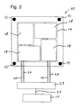
- FIG. 2 an embodiment of a transceiver tray 10 of the location system according to the invention is shown.
- this transceiver tray 10 four sub-trays 18 are disposed within the transceiver surface 14, each of which has transceiver surfaces and which are opposed to the bottom surface or bottom plane at a predetermined distance.
- the subtablets 18 are configured so that they can detect the position of each of a ground antenna within the tray area of the subtablet.
- the sub-trays 18 are connected via data lines 20, which transmit, for example, a USB protocol, with a data line node 22, which may be configured as a USB hub.
- the data lines 20 merged by the data line node 22 are supplied to the evaluation electronics 16 via a common data line 24.
- the subtablets 18 may have their own evaluation electronics in addition to the transceiver surface, in which case the fully evaluated position of a ground antenna within the sub-tablet level is already transmitted via the data lines 20 to the evaluation electronics 16 by means of a USB protocol.
- the transmitter 16 may be a PC or an integrated circuit.
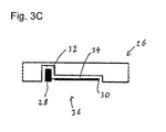
- FIGS. 3A to 3C For example, an embodiment of a floor panel 26 of a floor transceiver system according to the invention is shown.
- the surface of the bottom plate 26 of the bottom transceiver system has no changes in contour compared to a normal one Base plate, which can be coated for example in a television studio with a special color, as is common, for example, in the green-screen technique.
- the ground transceiver system of the invention is stain resistant, abrasion resistant and, moreover, highly resistant since all electronic components of the ground transceiver system are protected from moisture or other force effects by the bottom plate 26.
- FIG. 3B is a plan view of a bottom surface of the bottom plate 26 of the ground transceiver system of the invention.
- FIG. 3C is formed, arranged in the back of the bottom plate 26 as bottom antennas 28 coils arranged, which are each electrically connected to associated electronic boards 30.
- the coils 28 are arranged in cylindrical blind holes 32, which extend to just before the surface of the bottom plate 26.
- the electronic boards 30 may each be inserted in flat rectangular recesses 34 in the back of the bottom plate 26, whereby the bottom transceiver 36 formed from the coil 28 and electronics board 30 does not protrude from the back of the bottom plate 26.
- the blind holes 32 and the recesses 34 may be formed by the use of gypsum fiber-made bottom plates 26 by milling or drilling.
- the embodiment shown is only one example of a possible arrangement of the electronic board 30 and an associated coil 28, it is for example also possible to arrange both the electronic board 30 and the coil 28 in a blind hole 32, whereby for installation of the base transceiver 36 only holes must be drilled in the bottom plates 26.
- call navigation or odometry can be used. The information determined by dead reckoning is in this case used as long as the sub-trays 18 within the transceiver area 14 of the transceiver tray 10 can detect no bottom transceivers 36.
- the floor transceiver system For installation of the floor transceiver system within a room, which may be, for example, a television studio, a plurality of floor panels 26 are laid, the floor of the floor transceiver system being designed as a hollow floor system, as is well known.
- the modular design of the ground transceiver system of pavable floor panels 26 has the advantage that in case of failure of individual components of the ground transceiver system each individual floor panels 26 can be replaced without the entire floor system needs to be replaced.
- the corresponding ground antennas 28 are re-measured.
- the ground transceivers 36 are disposed in the bottom plate 26 such that the coils 28 are spaced at regular intervals in the bottom plate 26, with each spool or ground antenna 28 marking a corresponding location within the bottom plate 26 and thus within the ground plane of the ground transceiver system.
- the ground transceivers 36 are formed according to the invention as a transceiver, the coil 28 operates as a transmitting antenna as well as a receiving antenna for receiving energy, as it is also used in the RF-ID technique.
- the electronic board 30 connected to the coil 28 can in this case transmit its position within the ground plane to the transceiver tray 10.
- the electronics board 30 can in the simplest case transmit a unique bottom transceiver identifier to the transceiver tray 10, with all relevant data regarding a bottom transceiver 36 in the corresponding subtablets 18 or in the transmitter 16 are stored, which can be retrieved via the unique ground transceiver identifier.
- the coil 28 is inserted into the blind hole 32 of the bottom plate 26 that the winding axis of the coil 28 substantially perpendicular to the bottom plane of the bottom plate 26 is located.
- a quasi-point-shaped ground antenna 28 can be formed within the ground plane.
- the diameter of the coil 28 is about 1 mm.
- the coil diameter of the coil 28 may also be slightly larger, that is about 5 mm or 10 mm.
- the coil 28 is cylindrical and about 20 mm long, wherein the distance of the end of the coil 28 from the surface of the bottom plate 26, which corresponds approximately to the distance between the surface of the bottom plate 26 and the end of the blind hole 32, preferably less than 15 mm, more preferably less than 10 mm and in particular less than 5 mm in order to achieve the smallest possible distance between transceiver tray 10 and coil 28.
- a coil of a base transceiver may have a substantially larger diameter, that is about 50 mm to 150 mm, wherein the transceiver surface 14 of the transceiver tray 10 determines the center of the coil accordingly.
- the transceiver tray 10 is designed so that the correspondingly enlarged coil can be determined with the same precision with respect to their center point position.
- the correspondingly larger coil since it can be made correspondingly thinner, be placed in a PVC floor, whereby a roll-out bottom can be provided.
- the transceiver tray 10 is moved over the ground level of the ground transceiver system composed of the plurality of bottom plates 26.
- the spacers 12 are dimensioned such that the transceiver surfaces of the sub-trays 18 do not possibly come into contact with the ground plane in order to avoid abrasion of the transceiver surfaces of the sub-trays 18 or scratching them.
- the spacers 12 are selected so that the distance between the transceiver surface of the subtray 18 is kept as small as possible from the surface of the bottom plates 26.
- the mean distance between the transceiver surface the transceiver tray 10 and the bottom plane is preferably less than 15 mm, more preferably less than 10 mm and in particular less than 5 mm.
- the transceiver surface of a subtablet 18 is configured such that the position of the coil 28 which opposes the transceiver surface of the subtablet 18 during operation of the locator system can be located within the transceiver surface of the subtablet 18.
- 18 horizontally and vertically aligned antennas are arranged below the surface of the transmission receiving surface of the subtablet, which change between a transmission and a reception mode.
- This plurality of horizontally and vertically oriented antennas which are each designed as elongated induction loops, are arranged one above the other in two layers, so that an antenna grating is formed by the mutually perpendicular antennas, which is connected to an evaluation to an evaluation of the received Transmission strength to determine the position of a lying in the receiving field coil 28 exactly within the tablet level.
- the respective antennas of the transceiver surface emit an electromagnetic signal which excite a resonant circuit located in the transmission range of a base transceiver 36, which is formed from the coil 28 and a capacitor located in the electronic circuit board 30.
- a bottom transceiver 36 can be supplied with energy.
- the activated electronic board 30 then outputs via the coil in turn a signal to the respective coil 28 opposite antennas within the transceiver surface of a subtablet 18, wherein in this RF communication between an antenna within the transceiver surface of the subtablet 18 and the coil 28 and a position identifier or land-transceiver identifier can be transmitted.
- a subtablet 18 is adapted to be able to uniquely locate only one coil 28 of a bottom transceiver 36.
- the ground antennas or coils 28 are arranged within the ground plane so that in each case a coil 28 is located within a transmission receiving surface of a subtray 18.
- four sub-trays 18 are disposed within the transceiver 14 of the transceiver tray 10, and in addition, due to the overlapping of the four sub-trays 18 in the different directions, dead zones due to the four sub-trays 18 are also compensated within the receiving surface 14 can be.
- a loss of sub-trays or ground transceivers can also be compensated.
- known in the art known graphics tablets can be used, which have a resolution accuracy of about 1 mm, creating a high-precision localization system for a movable device is created within a room.
- the localization system according to the invention can be connected to other localization systems, it is possible, for example, to provide the floor provided with bottom transceivers 36 only at certain points in a room where a precise determination of the situation is necessary, with the location in intermediate areas can be determined via dead reckoning or odometry.
- the localization system according to the invention can advantageously also be used to recalibrate the displacement sensors used in an odometry, since the absolute determination of the position and orientation of a movable device is possible in the regions of the localization system according to the invention.
- a movable device which may be a camera robot or an industrial robot. Bridging intermediate areas within a room using odometry.
- this can be driven by means of a positioning system which moves the robot into areas which are equipped with the localization system according to the invention, within these areas inaccuracies in approaching a predetermined ground position can be compensated in a simple manner by a movement of the modroboterarms ,
- an industrial robot can be driven in front of a work area, whereby the accuracy of the approached location does not have to be high.
- This is followed by an exact determination of the position in the ground plane by the location system according to the invention with an accuracy in the millimeter range.
- This information is passed on to the industrial robot by means of a control device, whereby the industrial robot can drive his handheld or an attached film camera with millimeter accuracy to a predetermined position in the space of the work area.
- industrial robots can perform different tasks in different work areas and do not need to be re-taught because they know the exact position of their location in each work area and thus can move the robot hand, which can be moved with millimeter precision, precisely to a position in the room.
- the movable device can be used as a transport device in an autonomous storage system.
- the movable device which is equipped with a transceiver tray, as a transport or working robot in a biochemical laboratory, thereby providing a robot system which is simultaneously highly precise and has a long reach, and beyond can work in a highly sterile environment.
- work that had previously been performed by humans (in protective suits) due to the required precision be performed by the robot system according to the invention.
- Another possible application is, for example, in the transport of or work with hazardous substances, such as radioactive material. Explosives or pathogenic biological or chemical material.
- Another application of the location system according to the invention is, for example, the use of autonomous production robots. It is particularly advantageous that due to the non-contact location by means of RF communication, both the base transceiver system and the transceiver tray can be encapsulated, with pollution by dust. Oil or other dirt can be prevented, whereby a trouble-free operation is possible.
- the location system according to the invention has a number of advantages over the known positioning systems, which are used for example in television studios for camera robots.
- the localization system according to the invention achieves a uniquely high positioning accuracy in the millimeter range, which can not be achieved by RF-ID systems due to the corresponding antenna size.
- the locating system of the invention is very resistant, since the floor panels 26 are dirt and abrasion resistant. This is not the case with optical positioning systems known in the art.
- repair is possible almost only with a complete replacement of the floor system. In the system according to the invention, in which a plurality of bottom plates 26 are used, only one respective defective bottom plate has to be exchanged and the coils 28 located in the bottom plate have to be remeasured.
- the localization system according to the invention can be achieved by the localization system according to the invention, a high time resolution of less than 20 ms, which is often not possible in the known systems due to the high computational complexity by means of image processing.
- no installation on the ceiling or walls is necessary, as is the case, for example, with optical systems.
- the ground-based receiver system of the localization system of the present invention due to its unvarying surface, can be adapted to the respective requirements, for example, application of a particular color or markings is still possible regardless of the corresponding locating system.
- the locating system operates without contact, eliminating the need for maintenance of corresponding components due to abrasion (apart from the spacers 12).
Landscapes
- Engineering & Computer Science (AREA)
- Physics & Mathematics (AREA)
- Electromagnetism (AREA)
- Aviation & Aerospace Engineering (AREA)
- Radar, Positioning & Navigation (AREA)
- Remote Sensing (AREA)
- General Physics & Mathematics (AREA)
- Automation & Control Theory (AREA)
- Multimedia (AREA)
- Signal Processing (AREA)
- Control Of Position, Course, Altitude, Or Attitude Of Moving Bodies (AREA)
- Radar Systems Or Details Thereof (AREA)
Description
- Die Erfindung betrifft ein Lokalisierungssystem zur Bestimmung einer Lage einer auf einem Boden bewegbaren Vorrichtung, insbesondere eines verfahrbaren Roboters für Industrieanwendungen oder eines Kameraroboters.
- Bei der Produktion von Filmen und Fernsehsendungen werden oft virtuelle Welten eingesetzt, in denen die Protagonisten wie Schauspieler und Nachrichtensprecher eingespielt werden. Diese Technik ist unter anderem als Bluescreen- oder Greenscreen-Technik bekannt. Um bei der Aufnahme mittels einer Studiokamera diese virtuelle Welt später auf das reale Bild entsprechend perspektivisch richtig anzupassen, ist es nötig, die genaue Position des Brennpunkts der Studiokamera sowie deren Blickrichtung, also ihre Orientierung im Raum zu kennen.
- Für diesen Zweck werden üblicherweise eine Reihe passiver kodierter Targets in einer Studiobeleuchtungsanlage eingesetzt, die ständig beleuchtet und von einer kleinen, auf der Studiokamera montierten Tracking-Kamera erfasst werden. Jedes Target ist durch einen kreisförmigen Strichcode eindeutig gekennzeichnet, wobei die Verwendung von schmalbandigen LEDs und reflektierendem Material sicherstellt, dass unter normalen Beleuchtungsbedingungen im Studio immer eine ausreichende Anzahl von Targets sichtbar ist. Das Bild der Tracking-Kamera wird verarbeitet, um die exakte Position und Ausrichtung der Studiokamera zu berechnen. Aufgrund der Kenntnis der Position der Targets kann die Position und Orientierung der Studiokamera berechnet werden. Eine kommerzielle Anwendung dieses Positionierungsprinzips ist beispielsweise das Free-D-System der Firma RADAMEC Broadcast Robotics.
- In einem weiteren Lokalisierungssystem, welches durch die Firma MGS unter dem Produktnamen blue.i Studio Navigator vertrieben wird, werden Kameras eingesetzt, welche Servoachsen mit Drehgebern besitzen, wobei jederzeit die Stellung der einzelnen Achsen abgefragt und damit die Position der Kamera und ihre Orientierung bestimmt werden kann. Ferner ist die Kamera auf einem Gestell befestigt, das in dem Studio verfahrbar ist, wobei ein speziell gestalteter Boden eingesetzt wird, welcher ein digital kodiertes Muster aufweist, das mittels einer Kamera ausgelesen wird, die an dem Kameragestell montiert ist und über den Boden bewegt wird, wodurch die Position und relative Lage in der Bodenebene des Studios bestimmt werden kann. Um ein präzises Auslesen des Bodenmusters zu gewährleisten, muss jedoch der Boden schmutzfrei gehalten werden.
- Darüber hinaus sind Lokalisierungssysteme unter Verwendung von RF-ID-Sendern bekannt, welche in einem Lagerhallenboden für die Orientierung von Transportfahrzeugen oder in einem Teppich für automatische Staubsauger eingebracht sind, wobei das entsprechende Fahrzeug eine RF-ID-Antenne aufweist, um die RF-ID-Sender im Boden zu lokalisieren und entsprechende Fahranweisungen oder Orientierungshilfen zu erhalten. Um die RF-ID-Sender im Boden leicht orten zu können, sind die Antennen der zu lotsenden Fahrzeuge möglichst groß, wodurch jedoch die Präzision der Lokalisierung aufgrund der Größe der eingesetzten Antennen gering ist.
- Die
US 6,377, 888 B1 beschreibt ein System zur Steuerung einer Bewegung eines Fahrzeugs. Das System umfasst eine Vielzahl von Bodensendeempfängern, welche auf einer Bodenfläche vorgesehen sind und absolute Ortsdaten zur Verfügung stellen. Die Bodensendeempfänger sind in einem rechteckigen Gitter von gleich beabstandeten Reihen und Spalten angeordnet. Zumindest zwei Bodensendeempfängerlesevorrichtungen sind an einem Fahrzeug an dessen Unterseite montiert. Wenn das Fahrzeug sich über die Bodenfläche bewegt, passieren die Bodensendeempfängerlesevorrichtungen die Bodensendeempfänger und lesen die absoluten Ortsdaten von einem entsprechenden Bodensendeempfänger aus, der von einer Bodensendeempfängerlesevorrichtung überstrichen wird. Die absoluten Ortsdaten werden dazu verwendet, die absolute Position des Fahrzeugs zu berechnen. Wenn das Fahrzeug in einer Position ist, so dass zwei Bodensendeempfängerlesevorrichtungen über einen Bodensendeempfänger fahren, dann kann die absolute Orientierung des Fahrzeugs sowohl aus der Kenntnis der Orte der Bodensendeempfänger und der Position der an dem Fahrzeug montierten Bodensendeempfängerlesevorrichtungen berechnet werden. Ferner kann die Fahrzeuggeschwindigkeit und -beschleunigung aus einer Abfolge von absoluten. Positionen abgeleitet werden. - Der Erfindung liegt also die Aufgabe zugrunde, ein weiteres Lokalisierungssystem zur Bestimmung einer Lage einer entlang eines Bodens bewegbaren Vorrichtung zu schaffen, welches eine hohe Positioniergenauigkeit besitzt und gleichzeitig einen geringen Wartungsaufwand erfordert.
- Diese Aufgabe wird durch das Lokalisierungssystem nach Anspruch 1 gelöst. Vorteilhafte Ausgestaltungen und Weiterbildungen der Erfindung werden in den Unteransprüchen dargelegt.
- Erfindungsgemäß ist ein Lokalisierungssystem zur Bestimmung einer Lage einer auf einem Boden bewegbaren oder verfahrbaren Vorrichtung vorgesehen, mit einem Bodensendeempfängersystem mit einer Vielzahl von Bodensendeempfängern, welche jeweils Bodenantennen zur Markierung von Positionspunkten innerhalb der Bodenebene aufweisen, einem mit der bewegbaren Vorrichtung verbundenen Sendeempfängertablett mit einer Sendeempfangsfläche, die dem Boden gegenüberliegt und dazu geeignet ist, stets die Position von zumindest zwei Bodenantennen innerhalb der Sendeempfangsfläche gleichzeitig zu bestimmen. Hierbei soll unter dem Begriff Lage der bewegbaren Vorrichtung die Position der bewegbaren Vorrichtung sowie ihre Orientierung in der Bodenebene verstanden werden.
- Es ist also ein Lokalisierungssystem vorgesehen, bei welchem eine flächige Antennenanordnung eingesetzt wird, die an einer verfahrbaren Vorrichtung montiert und über einem Boden bewegt wird, wobei in der Bodenebene in vorbestimmten Abständen, beispielsweise in einer Wabenanordnung quasipunktförmige Antennen eingebracht sind, die durch die flächige Antennenanordnung lokalisiert werden können. Die flächige Antennenanordnung ist dabei so ausgestaltet, dass sie die Position einer punktförmigen Antenne in der Bodenebene innerhalb ihrer Empfangsfläche sehr genau, also etwa im Millimeterbereich detektieren kann. Die flächige Antennenanordnung ist dabei so ausgestaltet, dass sie gleichzeitig mindestens zwei Bodenantennen detektieren kann, um somit die Position und Orientierung der flächigen Antennenanordnung und somit der verfahrbaren Vorrichtung bestimmen zu können. Hierbei ist es besonders vorteilhaft, wenn die einzelnen Bodenantennen auf der Basis von Induktion arbeiten, wodurch eine externe Stromversorgung der Bodenantennen entfällt.
- Für eine reale Ausgestaltung eines Bodensendeempfänger ist es zweckmäßig, wenn ein Bodensendeempfänger eine als Bodenantenne ausgebildete Spule, deren Wicklungsachse im Wesentlichen senkrecht zur Bodenebene liegt, und eine mit der Spule elektrisch verbundene Elektronikplatine umfasst, welche für eine RF-Kommunikation mit dem Sendeempfängertablett ausgebildet ist. Somit kann also die Bodenantenne quasi-punktförmig in der Bodenebene ausgebildet sein, wodurch in besonders geeigneter Weise Positionspunkte innerhalb der Bodenebene markiert werden können.
- Um zu gewährleisten, dass die verfahrbare Vorrichtung auch ohne Einstellung ihrer ursprünglichen Startposition sofort ihre Position und Orientierung kennt, ist es zwecksmäßig, wenn die Elektronikplatine dazu geeignet ist, bei der RF-Kommunikation mit dem Sendeempfängertablett eine Positionskennung an dieses zu übertragen.
- Für eine einfache Unterbringung der Bodensendeempfänger innerhalb eines Bodens ist es von Vorteil, wenn die Spule eines Bodensendeempfängers einen Durchmesser von kleiner als 5 mm und insbesondere kleiner als 2 mm aufweist. Hierbei können die Bodensendeempfänger, also eine Spule zusammen mit einer Elektronikplatine, in Löcher eingesetzt werden, die direkt in einen bestehenden Boden gebohrt wurden, da eine Verkabelung aufgrund der Stromversorgung durch das Sendeempfängertablett entfällt.
- Für eine einfache Installation des Bodensendeempfängersystems oder eine einfache Wartung bei einem Ausfall von Bodensendeempfängern ist es besonders zweckmäßig, wenn das Bodensendeempfängersystem eine Vielzahl von Bodenplatten aufweist, wobei die Spulen der Bodensendeempfänger jeweils so in rückseitigen Sacklöchern der Bodenplatte aufgenommen sind, dass der Abstand zwischen Bodenoberfläche und Spulenende kleiner als 15 mm, vorzugsweise kleiner als 10 mm und insbesondere kleiner als 5 mm ist.
- Hierbei ist die Bodenplatte vorteilhafter Weise aus Gipsfasern hergestellt, wobei die Sacklöcher durch Bohren gebildet werden können.
- Für den mobilen Einsatz des erfindungsgemäßen Lokalisierungssystems ist es besonders von Vorteil, wenn die Spule eines Bodensendeempfängers als flächige Spule in einem ausrollbaren, flexiblen Boden ausgebildet ist, wodurch der Boden in einfacher Weise transportiert werden kann. Hierbei ist es zweckmäßig, den Durchmesser der Spulen des Bodensendeempfängers im Bereich zwischen 50 mm und 150 mm zu wählen.
- Für die Verwirklichung eines präzisen Lokalisierungssystems für eine verfahrbare Vorrichtung, beispielsweise für eine Studiokamera in einem Fernsehstudio ist es zweckmäßig, wenn der mittlere Abstand zwischen der Sendeempfängerfläche des Sendeempfängertabletts und der Bodenebene kleiner als 15 mm, vorzugsweise kleiner als 10 mm und insbesondere kleiner als 5 mm ist.
- In einer bevorzugten Ausgestaltung eines Sendeempfängertabletts weist dieses Abstandshalter auf, um die Sendeempfangsfläche des Sendeempfängertabletts in einem vorbestimmten Abstand von der Bodenebene zu halten.
- Zweckmäßiger Weise sind hierbei die Abstandhalter aus Kunststoff gefertigt, wobei diese nach einem Verschleiß einfach ausgetauscht werden können.
- Für eine einfache Ausgestaltung der Erfindung, welche hinsichtlich der Lokalisierung und Erkennung von Bodenantennen einen möglichst geringen Programmieraufwand benötigt, ist es zweckmäßig, wenn das Sendeempfängertablett aus mehreren Untertabletts zur Detektion jeweils einer Position einer Bodenantenne eines Bodensenderempfängers zusammengesetzt ist, wobei die Bodenantennen der Bodensendeempfänger so in der Bodenebene angeordnet sind, dass in jeder Lage des Sendeempfängertabletts immer eine Bodenantenne im Detektionsbereich eines Untertabletts liegt. Hierbei kann vorteilhafter Weise das Sendeempfängertablett mindestens zwei Untertabletts aufweisen.
- Für den Einsatz des erfindungsgemäßen Lokalisierungssystems in einem Filmstudio ist es von Vorteil, wenn die bewegbare Vorrichtung ein verfahrbarer Kameraroboter oder Industrieroboter ist. Hierbei ist es jedoch auch vorstellbar, als bewegbare Vorrichtung ein Kamerastativ vorzusehen.
- Der Einsatz des erfindungsgemäßen Lokalisierungssystems bei einem verfahrbaren Industrieroboter oder Kameraroboter hat den besonderen Vorteil, dass bei einem Anfahren einer vorbestimmten Position einer Kamera oder einer Roboterhand ein verfahrbarer Untersatz des Roboters zunächst an eine vorbestimmte Bodenposition durch ein im verfahrbaren Untersatz befindliches Stellsystem gefahren wird, wobei die naturbedingte Ungenauigkeit der angefahrenen Bodenposition aufgrund des Verstellsystems des verfahrbaren Untersatzes in einfacher Weise dadurch ausgeglichen werden kann, dass die Position in der Bodenebene millimetergenau durch das Lokalisierungssystem bestimmt wird und die nicht exakt angefahrene Standposition des verfahrbaren Untersatzes des Industrie- oder Kameraroboters durch die Kamerarobotik, also durch die millimetergenaue Bewegung der Roboterarme ausgeglichen wird. Somit kann durch Kombination von Kamerarobotik und Lokalisierungssystem ein verfahrbarer Roboter geschaffen werden, welcher eine Roboterhand oder eine Filmkamera millimetergenau an eine Position in einem Raum bewegen kann.
- Schließlich ist es vorteilhaft, wenn die bewegbare Vorrichtung ein verfahrbares Luftkissensystem mit einem Roboter für den Industrieeinsatz oder einem Kameraroboter ist.
- Die Erfindung wird im Folgenden beispielsweise anhand der Zeichnung näher erläutert. Es zeigen:
-
Figur 1 eine stark vereinfachte schematische Ansicht eines Sendeempfängertabletts gemäß der Erfindung, -
Figur 2 eine stark vereinfachte schematische Ansicht eines Sendeempfängertabletts gemäß einem Ausführungsbeispiel der Erfindung, -
Figur 3A eine vereinfachte schematische Draufsicht auf eine Oberseite einer Bodenplatte eines erfindungsgemäßen Bodensendeempfängersystems. -
Figur 3B eine vereinfachte schematische Draufsicht auf eine Rückseite der Bodenplatte des erfindungsgemäßen Bodensendeempfängersystems, und -
Figur 3C eine vereinfachte schematische Schnittansicht entlang einer Linie A-A' inFig. 3B der Bodenplatte des erfindungsgemäßen Bodensendeempfängersystems. - In den verschiedenen Figuren der Zeichnung sind einander entsprechende Bauelemente mit gleichen Bezugszeichen versehen.
- In
Figur 1 ist ein Ausführungsbeispiel eines Sendeempfängertabletts 10 des Lokalisierungssystems gemäß der Erfindung gezeigt. - Das Sendeempfängertablett 10 ist dazu vorgesehen, mit einer bewegbaren oder verfahrbaren Vorrichtung verbunden zu werden, wobei die Unterseite (wie in
Figur 1 gezeigt) des Sendeempfängertabletts 10 einer Bodenebene gegenüberliegt, in welcher Bodensendeempfänger eingebracht sind, die im Folgenden noch genauer beschrieben werden. Das Sendeempfängertablett kann hierfür Abstandshalter 12 aus Kunststoff aufweisen, um die Unterseite des Sendeempfängertabletts 10 von der Bodenebene oder der Bodenfläche in einem definierten Abstand zu halten. Das Sendeempfängertablett 10 wird also vorzugsweise über eine Bodenebene bewegt, es ist jedoch auch vorstellbar, als Abstandshalter 12 kleine. Kugelrollen vorzusehen. Das Sendeempfängertablett 10 wird so an der verfahrbaren Vorrichtung (nicht gezeigt) angebracht, dass es in Horizontalrichtung frei beweglich ist, um so einen steten Kontakt der Abstandshalter 12 und des Sendeempfängertabletts 10 mit dem Boden zu erreichen. Hierbei ist es jedoch entscheidend, dass die relative Lage des Sendeempfängertabletts 10 in Bezug auf die verfahrbare Vorrichtung innerhalb der Bodenebene fest ist, um somit die Orientierung und Position der verfahrbaren Vorrichtung mittels der Position und Orientierung des Sendeempfängertabletts 10 genau bestimmen zu können. Als verfahrbare Vorrichtung wird vorzugsweise ein Kameraroboter eingesetzt, welcher auf einem mittels Rollen verfahrbaren Kameragestell sitzt, es ist jedoch auch vorstellbar, den Kameraroboter auf einer verfahrbaren Luftkissenplattform zu positionieren. - Das Sendeempfängertablett 10 weist an seiner Unterseite eine Sendeempfangsfläche 14 auf, die in einem vorbestimmten Abstand der Bodenebene gegenüberliegt, und welche dazu geeignet ist, die Position von zumindest zwei Bodenantennen zu bestimmen. Die Sendeempfangsfläche 14 ist mit einer Auswerteelektronik 16 verbunden, um die von der Sendeempfangsfläche 14 empfangenen Signale auszuwerten.
- In
Figur 2 ist ein Ausführungsbeispiel eines Sendeempfängertabletts 10 des Lokalisierungssystems gemäß der Erfindung gezeigt. Bei diesem Sendeempfängertablett 10 sind innerhalb der Sendeempfangsfläche 14 vier Untertabletts 18 angeordnet, die jeweils Sendeempfangsflächen aufweisen und welche der Bodenfläche oder Bodenebene in einem vorbestimmten Abstand gegenüberliegen. Die Untertabletts 18 sind so ausgestaltet, dass diese die Lage jeweils einer Bodenantenne innerhalb des Tablettbereichs des Untertabletts detektieren können. Die Untertabletts 18 sind über Datenleitungen 20, welche beispielsweise ein USB-Protokoll übertragen, mit einem Datenleitungsknotenpunkt 22 verbunden, welcher als USB-Hub ausgebildet sein kann. Die von dem Datenleitungsknotenpunkt 22 zusammengeführten Datenleitungen 20 werden über eine gemeinsame Datenleitung 24 der Auswerteelektronik 16 zugeführt. Die Untertabletts 18 können neben der Sendeempfangsfläche eine eigene Auswerteelektronik aufweisen, wobei dann über die Datenleitungen 20 bereits die vollständig ausgewertete Position einer Bodenantenne innerhalb der Untertablettebene an die Auswerteelektronik 16 mittels eines USB-Protokolls übermittelt wird. Die Auswerteelektronik 16 kann hierbei ein PC oder eine integrierte Schaltung sein. - In den
Figuren 3A bis 3C ist ein Ausführungsbeispiel einer Bodenplatte 26 eines Bodensendeempfängersystems gemäß der Erfindung gezeigt. - Wie in
Figur 3A in der Draufsicht auf die Oberseite der Bodenplatte 26 deutlich wird, weist die Oberfläche der Bodenplatte 26 des Bodensendeempfängersystems keine Veränderungen in der Kontur im Vergleich zu einer normalen Bodenplatte auf, wodurch diese beispielsweise in einem Fernsehstudio mit einer speziellen Farbe beschichtet werden kann, wie dies beispielsweise bei der Green-Screen-Technik üblich ist. Zudem ist das Bodensendeempfängersystem der Erfindung schmutz- und abriebfest und darüber hinaus sehr widerstandsfähig, da sämtliche elektronische Komponenten des Bodensendeempfängersystems vor Feuchtigkeit oder sonstigen Krafteinwirkungen durch die Bodenplatte 26 geschützt sind. - In
Figur 3B ist eine Draufsicht auf eine Unterseite der Bodenplatte 26 des Bodensendeempfängersystems der Erfindung gezeigt. Wie ausFigur 3C deutlich wird, welche eine seitliche Schnittansicht entlang einer Linie A-A' inFig. 3B darstellt, sind in der Rückseite der Bodenplatte 26 als Bodenantennen 28 ausgebildete Spulen angeordnet, die jeweils mit zugehörigen Elektronikplatinen 30 elektrisch verbunden sind. Die Spulen 28 sind in zylinderförmigen Sacklöchern 32 angeordnet, welche bis knapp vor die Oberfläche der Bodenplatte 26 reichen. Die Elektronikplatinen 30 können jeweils in flachen rechteckförmigen Ausnehmungen 34 in der Rückseite der Bodenplatte 26 eingelegt sein, wodurch die aus der Spule 28 und Elektronikplatine 30 gebildeten Bodensendeempfänger 36 nicht von der Rückseite der Bodenplatte 26 hervorragen. - Die Sacklöcher 32 und die Ausnehmungen 34 können bei der Verwendung von aus Gipsfasern gefertigten Bodenplatten 26 durch Fräsen oder durch Bohren gebildet werden. Die in
Fig. 3B und3C gezeigte Ausführungsform ist jedoch nur ein Beispiel für eine mögliche Anordnung der Elektronikplatine 30 und einer zugehörigen Spule 28, es ist beispielsweise auch möglich, sowohl die Elektronikplatine 30 als auch die Spule 28 in einem Sackloch 32 anzuordnein, wodurch für eine Installation der Bodensendeempfänger 36 lediglich Löcher in die Bodenplatten 26 gebohrt werden müssen. Um den Abstand zwischen den einzelnen Bodensendeempfängern 36 zu erhöhen, kann in einem Ausführungsbeispiel auf Koppelnavigation bzw. Odometrie zurückgegriffen werden. Die durch Koppelnavigation ermittelte Information wird hierbei solange verwendet, wie die Untertabletts 18 innerhalb der Sendeempfangsfläche 14 des Sendeempfängertabletts 10 keine Bodensendeempfänger 36 detektieren können. - Im Folgenden soll nun die Funktionsweise und das Zusammenwirken des Sendeempfängertabletts 10 mit dem Bodensendeempfängersystem, welches aus einer Vielzahl von Bodenplatten 26 zusammengesetzt ist, beschrieben werden.
- Für eine Installation des Bodensendeempfängersystems innerhalb eines Raums, welcher beispielsweise ein Fernsehstudio sein kann, werden eine Vielzahl von Bodenplatten 26 verlegt, wobei der Boden des Bodensendeempfängersystems als Hohlbödensystem, wie es allgemein bekannt ist, ausgestaltet sein kann. Der modulare Aufbau des Bodensendeempfängersystems aus pflasterbaren Bodenplatten 26 hat den Vorteil, dass im Falle eines Ausfalls von einzelnen Komponenten des Bodensendeempfängersystems jeweils einzelne Bodenplatten 26 ausgetauscht werden können, ohne dass das komplette Bodensystem ausgetauscht werden muss. Hierbei werden nach einem Austausch der Bodenplatte 26 die entsprechenden Bodenantennen 28 neu eingemessen.
- Die Bodensendeempfänger 36 sind in der Bodenplatte 26 so angeordnet, dass die Spulen 28 in regelmäßigen Abständen in der Bodenplatte 26 angeordnet sind, wobei jede Spule oder Bodenantenne 28 einen entsprechenden Positionspunkt innerhalb der Bodenplatte 26 und damit innerhalb der Bodenebene des Bodensendeempfängersystems markiert. Die Bodensendeempfänger 36 sind gemäß der Erfindung als Sender-Empfänger ausgebildet, wobei die Spule 28 als Sendeantenne wie auch als Empfangsantenne zur Aufnahme von Energie arbeitet, wie es auch in der RF-ID-Technik verwendet wird. Die mit der Spule 28 verbundene Elektronikplatine 30 kann hierbei ihre Position innerhalb der Bodenebene an das Sendeempfängertablett 10 übermitteln. Dabei ist es jedoch nicht nötig, dass die Elektronikplatine 30 sämtliche Positionsdaten übermittelt, sondern die Elektronikplatine 30 kann im einfachsten Fall eine eindeutige Bodensendeempfängerkennung an das Sendeempfängertablett 10 übertragen, wobei sämtliche relevante Daten hinsichtlich eines Bodensendeempfängers 36 in den entsprechenden Untertabletts 18 oder in der Auswerteelektronik 16 abgespeichert sind, welche über die eindeutige Bodensendeempfängerkennung abgerufen werden können.
- Wie in
Figur 3C gezeigt, ist die Spule 28 so in das Sackloch 32 der Bodenplatte 26 eingesetzt, dass die Wicklungsachse der Spule 28 im wesentlichen senkrecht zur Bodenebene der Bodenplatte 26 liegt. Somit kann aufgrund der Abstrahlrichtung und Empfangsrichtung der Spule 28 eine quasi-punktförmige Bodenantenne 28 innerhalb der Bodenebene gebildet werden. Der Durchmesser der Spule 28 ist hierbei etwa 1 mm. Der Spulendurchmesser der Spule 28 kann jedoch auch etwas größer sein, also etwa 5 mm oder 10 mm. Bei der Verwendung von festen Bodenplatten ist es jedoch von Vorteil, wenn der Spulendurchmesser der Spule 28 gering gehalten wird, um in einfacher Weise Löcher in eine Bodenplatte 26 bohren zu können. Die Spule 28 ist zylinderförmig aufgebaut und etwa 20 mm lang, wobei der Abstand des Endes der Spule 28 von der Oberfläche der Bodenplatte 26, welcher in etwa dem Abstand zwischen Oberfläche der Bodenplatte 26 und dem Ende des Sacklochs 32 entspricht, vorzugsweise kleiner 15 mm, besonders bevorzugt kleiner 10 mm und insbesondere kleiner 5 mm ist, um einen möglichst geringen Abstand zwischen Sendeempfängertablett 10 und Spule 28 zu erreichen. - In einer anderen Ausgestaltung der Erfindung, welche nicht gezeigt ist, kann eine Spule eines Bodensendeempfängers jedoch einen wesentlichen größeren Durchmesser aufweisen, also etwa 50 mm bis 150 mm, wobei die Sendeempfangsfläche 14 des Sendeempfängertabletts 10 den Mittelpunkt der Spule entsprechend bestimmt. Hierbei ist das Sendeempfängertablett 10 so ausgestaltet, dass die entsprechend vergrößerte Spule mit der gleichen Präzision hinsichtlich ihrer Mittelpunktslage bestimmt werden kann. Die entsprechend größere Spule kann, da sie entsprechend dünner gefertigt werden kann, in einem PVC-Boden eingebracht sein, wodurch ein ausrollbarer Boden bereitgestellt werden kann.
- Im Einsatz des Lokalisierungssystems zur Bestimmung der Lage der entlang der Bodenebene verfahrbaren Vorrichtung gemäß der Erfindung wird das Sendeempfängertablett 10 über die Bodenebene des Bodensendeempfängersystems, welches aus der Vielzahl von Bodenplatten 26 zusammengesetzt ist, bewegt. Die Abstandshalter 12 sind dabei so bemessen, dass die Sendeempfangsflächen der Untertabletts 18 möglichst nicht in Berührung mit der Bodenebene gelangen, um einen Abrieb der Sendeempfangsflächen der Untertabletts 18 oder ein Verkratzen dieser zu vermeiden. Im Übrigen sind jedoch die Abstandshalter 12 so gewählt, dass der Abstand zwischen der Sendeempfangsfläche der Untertabletts 18 von der Oberfläche der Bodenplatten 26 möglichst gering gehalten wird. Der mittlere Abstand zwischen der Sendeempfangsfläche des Sendeempfängertabletts 10 und der Bodenebene ist dabei vorzugsweise kleiner als 15 mm, besonders bevorzugt kleiner als 10 mm und insbesondere kleiner als 5 mm.
- Die Sendeempfangsfläche eines Untertabletts 18 ist so ausgestaltet, dass die Position der Spule 28. die im Betrieb des Lokalisierungssystems der Sendeempfangsfläche des Untertabletts 18 gegenüberliegt, innerhalb der Sendeempfangsfläche des Untertabletts 18 lokalisiert werden kann. Für diesen Zweck sind unter der Oberfläche der Sendeempfangsfläche des Untertabletts 18 horizontal und vertikal ausgerichtete Antennen angeordnet, welche zwischen einem Sende- und einem Empfangsmodus wechseln. Diese Vielzahl von horizontal und vertikal ausgerichteten Antennen, welche jeweils als längsgestreckte Induktionsschlaufen ausgebildet sind, sind in zwei Schichten übereinander angeordnet, so dass durch die senkrecht zueinander angeordneten Antennen ein Antennengitter gebildet wird, welches mit einer Auswerteelektronik verbunden ist, um mittels einer Auswertung der empfangenen Sendestärke die Position einer im Empfangsfeld liegenden Spule 28 genau innerhalb der Tablettebene bestimmen zu können. Die entsprechenden Antennen der Sendeempfangsfläche senden ein elektromagnetisches Signal aus, welche einen im Sendebereich liegenden Schwingkreis eines Bodensendeempfängers 36 anregen, der aus der Spule 28 und einem in der Elektronikplatine 30 befindlichen Kondensator gebildet wird. Somit kann über den Schwingkreis ein Bodensendeempfänger 36 mit Energie versorgt werden. Die aktivierte Elektronikplatine 30 gibt dann über die Spule wiederum ein Signal an die der jeweiligen Spule 28 gegenüberliegenden Antennen innerhalb der Sendeempfangsfläche eines Untertabletts 18 aus, wobei bei dieser RF-Kommunikation zwischen einer Antenne innerhalb der Sendeempfangsfläche des Untertabletts 18 und der Spule 28 auch eine Positionskennung oder Bodensendeempfängerkennung übermittelt werden kann.
- In einer einfachen Ausführungsform der Erfindung, wie sie in
Fig. 2 gezeigt ist, ist ein Untertablett 18 dazu geeignet, nur jeweils eine Spule 28 eines Bodensendeempfängers 36 eindeutig lokalisieren zu können. Somit ist es bei dieser Ausführungsform vorteilhaft, wenn die Bodenantennen oder Spulen 28 innerhalb der Bodenebene so angeordnet sind, dass jeweils eine Spule 28 innerhalb einer Sendeempfangsfläche eines Untertabletts 18 befindlich ist. Um die Orientierung und Lage des Sendeempfängertabletts 10 eindeutig bestimmen zu können, sind daher in diesem Ausführungsbeispiel vier Untertabletts 18 innerhalb der Sendeempfangsfläche 14 des Sendeempfängertabletts 10 angeordnet, wobei zusätzlich durch die modulare Anordnung aufgrund des Überlapps der vier Untertabletts 18 in den verschiedenen Richtungen auch innerhalb der Empfangsfläche 14 liegende Totbereiche durch die vier Untertabletts 18 kompensiert werden können. Darüber hinaus kann aufgrund der Verwendung von vier Untertabletts 18 auch ein Ausfall von Untertabletts oder Bodensendeempfängern kompensiert werden. - Als Untertabletts 18 können beispielsweise im Stand der Technik bekannte Grafiktabletts eingesetzt werden, welche eine Auflösungsgenauigkeit von etwa 1 mm besitzen, wodurch ein hochpräzises Lokalisierungssystem für eine verfahrbare Vorrichtung innerhalb eines Raums geschaffen wird.
- Bei einem praktischen Einsatz kann das erfindungsgemäße Lokalisierungssystem mit anderen Lokalisierungssystemen verbunden werden, so ist es beispielsweise möglich, den mit Bodensendeempfängern 36 versehenen Boden nur an bestimmten Stellen in einem Raum vorzusehen, an welchen eine präzise Bestimmung der Lage nötig ist, wobei in Zwischenbereichen die Lage über Koppelnavigation bzw. Odometrie bestimmt werden kann. Hierbei kann das erfindungsgemäße Lokalisierungssystem vorteilhafterweise auch dazu verwendet werden, die bei einer Odometrie verwendeten Wegsensoren entsprechend nachzukalibrieren, da in den Bereichen des erfindungsgemäßen Lokalisierungssystems die absolute Bestimmung der Position und Orientierung einer bewegbaren Vorrichtung möglich ist. Somit kann also eine bewegbare Vorrichtung, welche ein Kameraroboter oder ein Industrieroboter sein kann. Zwischenbereiche innerhalb eines Raums mittels Odometrie überbrücken.
- Bei einem Einsatz eines Industrieroboters kann dieser mittels eines Stellsystems, welches den Roboter verfährt, in Bereiche gefahren werden, welche mit dem erfindungsgemäßen Lokalisierungssystem ausgestattet sind, wobei innerhalb dieser Bereiche Ungenauigkeiten beim Anfahren einer vorbestimmten Bodenposition in einfacher Weise durch eine Bewegung des Kameraroboterarms ausgeglichen werden können. So kann ein Industrieroboter beispielsweise vor einen Arbeitsbereich gefahren werden, wobei die Genauigkeit des angefahrenen Ortes nicht hoch sein muss. Danach erfolgt eine exakte Bestimmung der Position in der Bodenebene durch das erfindungsgemäße Lokalisierungssystem mit einer Genauigkeit im Millimeterbereich. Diese Information wird an den Industrieroboter mittels einer Steuerungsvorrichtung weitergegeben, wodurch der Industrieroboter seine Hand- oder eine angebrachte Filmkamera millimetergenau an eine vorbestimmte Position im Raum des Arbeitsbereichs fahren kann. Dadurch können Industrieroboter unterschiedliche Tätigkeiten in unterschiedlichen Arbeitsbereichen durchführen und müssen nicht neu eingelernt werden, da sie in jedem Arbeitsbereich die exakte Position ihres Standortes kennen und somit die Roboterhand, welche millimetergenau bewegt werden kann, präzise an eine Position im Raum bewegen können.
- Für die Ausgestaltung der bewegbaren Vorrichtung gibt es eine Reihe an Möglichkeiten. So kann die bewegbare Vorrichtung als Transportvorrichtung in einem autonomen Lagerhaltungssystem verwendet werden. Ferner ist es denkbar, die bewegbare Vorrichtung, welche mit einem Sende-Empfänger-Tablett ausgestattet ist, als Transport- oder Arbeitsroboter in einem biochemischen Labor vorzusehen, wodurch ein Robotersystem geschaffen wird, welches gleichzeitig hochpräzise ist und eine hohe Reichweite aufweist, und darüber hinaus in einem hochsterilen Umfeld arbeiten kann. Somit können Arbeiten, welche aufgrund der benötigten Präzision bislang durch Menschen (in Schutzanzügen) durchgeführt werden mussten, durch das erfindungsgemäße Robotersystem durchgeführt werden. Ein weiteres mögliches Einsatzgebiet liegt beispielsweise im Transport von oder der Arbeit mit Gefahrenstoffen, wie beispielsweise radioaktivem Material. Sprengstoffen oder krankheitserregendem biologischen oder chemischen Material.
- Eine weitere Anwendung des erfindungsgemäßen Lokalisierungssystems ist beispielsweise der Einsatz von autonomen Fertigungsrobotern. Hierbei ist besonders vorteilhaft, dass aufgrund der berührungsfreien Lokalisierung mittels RF-Kommunikation sowohl das Bodensendeempfängersystem als auch das Sendeempfängertablett verkapselt sein kann, wobei eine Verschmutzung durch Staub. Öl oder sonstigen Schmutz verhindert werden kann, wodurch ein störungsfreier Betrieb ermöglicht wird.
- Das erfindungsgemäße Lokalisierungssystem weist eine Vielzahl von Vorteilen gegenüber den bekannten Positioniersystemen auf, die beispielsweise in Fernsehstudios für Kameraroboter eingesetzt werden.
- So erreicht das erfindungsgemäße Lokalisierungssystem eine einzigartig hohe Positioniergenauigkeit im Millimeterbereich, welche von RF-ID-Systemen aufgrund der entsprechenden Antennengröße nicht erreicht werden kann. Weiter ist das Lokalisierungssystem der Erfindung sehr widerstandsfähig, da die Bodenplatten 26 schmutz- und abriebfest sind. Dies ist bei optischen Positioniersystemen, die im Stand der Technik bekannt sind, nicht der Fall. Des weiteren ist bei den bekannten Lokalisierungssystemen eine Reparatur fast nur mit einem kompletten Austausch des Bodensystems möglich. Bei dem erfindungsgemäßen System, bei welchem eine Vielzahl von Bodenplatten 26 eingesetzt werden, muss nur eine jeweilige defekte Bodenplatte ausgetauscht und die in der Bodenplatte befindlichen Spulen 28 neu eingemessen werden. Darüber hinaus kann durch das erfindungsgemäße Lokalisierungssystem eine hohe Zeitauflösung von unter 20 ms erreicht werden, was bei den bekannten Systemen aufgrund des hohen Rechenaufwands mittels Bildverarbeitung oft nicht möglich ist. Im Vergleich zu bekannten Systemen ist auch keine Installation an der Decke oder Wänden nötig, wie dies beispielsweise bei optischen Systemen der Fall ist. Somit entfällt der üblicherweise schwierige Vermessungsvorgang der optischen Targets innerhalb eines Raums. Das Bodensendeempfängersystem des Lokalisierungssystems der vorliegenden Erfindung kann darüber hinaus aufgrund seiner unveränderten Oberfläche den entsprechenden Anforderungen angepasst werden, so ist beispielsweise das Auftragen einer bestimmten Farbe oder von bestimmten Bodenmarkierungen weiterhin ohne Rücksicht auf das entsprechende Lokalisierungssystem möglich. Schließlich arbeitet das Lokalisierungssystem berührungslos, wodurch eine Wartung von entsprechenden Bauteilen aufgrund eines Abriebs (abgesehen von den Abstandshaltern 12) entfällt.
Claims (14)
- Lokalisierungssystem zur Bestimmung einer Lage einer auf einem Boden bewegbaren Vorrichtung mit:- einem Bodensendeempfängersystem mit einer Vielzahl von Bodensendeempfängern (36), welche jeweils Bodenantennen (28) zur Markierung von Positionspunkten innerhalb der Bodenebene aufweisen, und- einem mit der verfahrbaren Vorrichtung verbundenen Sendeempfängertablett (10) mit einer Sendeempfangsfläche (14), die dem Boden gegenüberliegt, dadurch gekennzeichnet, dass die Sendeempfangsfläche (14) dazu geeignet ist, stets die Lage von zumindest zwei Bodenantennen (28) innerhalb der Sendeempfangsfläche (14) gleichzeitig zu bestimmen.
- Lokalisierungssystem nach Anspruch 1, dadurch gekennzeichnet, dass ein Bodensendeempfänger (36) Folgendes umfasst:- eine als Bodenantenne ausgebildete Spule (28), deren Wicklungsachse im Wesentlichen senkrecht zur Bodenebene liegt, und- eine mit der Spule (38) elektrisch verbundene Elektronikplatine (30), welche für eine RF-Kommunikation mit dem Sendeempfängertablett (10) ausgebildet ist.
- Lokalisierungssystem nach Anspruch 2, dadurch gekennzeichnet, dass die Elektronikplatine (30) dazu geeignet ist, bei der RF-Kommunikation mit dem Sendeempfängertablett (10) eine Positionskennung an dieses zu übertragen.
- Lokalisierungssystem nach Anspruch 2 oder 3, dadurch gekennzeichnet, dass die Spule (28) eines Bodensendeempfängers (36) einen Durchmesser von kleiner als 5 mm und insbesondere kleiner als 2 mm aufweist.
- Lokalisierungssystem nach einem der Ansprüche 2 bis 4, dadurch gekennzeichnet, dass das Bodensendeempfängersystem eine Vielzahl von Bodenplatten (26) aufweist, wobei die Spulen (28) der Bodensendeempfänger (36) jeweils so in rückseitigen Sacklöchern (32) der Bodenplatte (26) aufgenommen sind, dass der Abstand zwischen Bodenoberfläche und Spulenende kleiner als 15 mm, vor zugsweise kleiner als 10 mm und insbesondere kleiner als 5 mm ist.
- Lokalisierungssystem nach Anspruch 5, dadurch gekennzeichnet, dass die Bodenplatte (26) aus Gipsfasern ist, wobei die Sacklöcher (32) durch Bohren gebildet sind.
- Lokalisierungssystem nach Anspruch 2 oder 3, dadurch gekennzeichnet, dass die Spule (28) eines Bodensendeempfängers (36) als flächige Spule in einem ausrollbaren Boden eingebettet ist.
- Lokalisierungssystem nach einem der vorstehenden Ansprüche, dadurch gekennzeichnet, dass der mittlere Abstand zwischen der Sendeempfängerfläche (14) des Sendeempfängertabletts (10) und der Bodenebene kleiner als 15 mm, vorzugsweise kleiner als 10 mm und insbesondere kleiner als 5 mm ist.
- Lokalisierungssystem nach einem der vorstehenden Ansprüche, dadurch gekennzeichnet, dass das Sendeempfängertablett (10) Abstandshalter (12) aufweist, um die Sendeempfangsfläche (14) des Sendeempfängertabletts (10) in einem vorbestimmten Abstand von der Bodenebene zu halten.
- Lokalisierungssystem nach Anspruch 9, dadurch gekennzeichnet, dass die Abstandshalter (12) aus Kunststoff sind.
- Lokalisierungssystem nach einem der vorstehenden Ansprüche, dadurch gekennzeichnet, dass das Sendeempfängertablett (10) aus mehreren Untertabletts (18) zur Detektion jeweils einer Position einer Bodenantenne (28) eines Bodensenderempfängers (36) zusammengesetzt ist, wobei die Bodenantennen (28) der Bodensendeempfänger (36) so in der Bodenebene angeordnet sind, dass in jeder Lage des Sendeempfängertabletts (10) immer eine Bodenantenne (28) im Detektionsbereich eines Untertabletts (18) liegt.
- Lokalisierungssystem nach Anspruch 11, dadurch gekennzeichnet, dass das Sendeempfängertablett (10) mindestens zwei Untertabletts (18) aufweist.
- Lokalisierungssystem nach einem der vorstehenden Ansprüche, dadurch gekennzeichnet, dass die bewegbare Vorrichtung ein verfahrbarer Kameraroboter, ein Industrieroboter oder ein Kamerastativ ist.
- Lokalisierungssystem nach einem der Ansprüche 1 bis 12, dadurch gekennzeichnet, dass die bewegbare Vorrichtung ein verfahrbares Luftkissensystem mit einem Roboter für den Industrieeinsatz oder mit einem Kameraroboter ist.
Applications Claiming Priority (2)
| Application Number | Priority Date | Filing Date | Title |
|---|---|---|---|
| DE202009000643U DE202009000643U1 (de) | 2009-01-20 | 2009-01-20 | Lokalisierungssystem zur Bestimmung einer Lage einer auf einem Boden bewegbaren Vorrichtung |
| PCT/EP2010/000279 WO2010083977A2 (de) | 2009-01-20 | 2010-01-19 | Lokalisierungssystem zur bestimmung einer lage einer auf dem boden bewegbaren vorrichtung |
Publications (2)
| Publication Number | Publication Date |
|---|---|
| EP2389757A2 EP2389757A2 (de) | 2011-11-30 |
| EP2389757B1 true EP2389757B1 (de) | 2013-07-31 |
Family
ID=40577522
Family Applications (1)
| Application Number | Title | Priority Date | Filing Date |
|---|---|---|---|
| EP10703799.6A Active EP2389757B1 (de) | 2009-01-20 | 2010-01-19 | Lokalisierungssystem zur bestimmung einer lage einer auf dem boden bewegbaren vorrichtung |
Country Status (5)
| Country | Link |
|---|---|
| US (1) | US8421674B2 (de) |
| EP (1) | EP2389757B1 (de) |
| JP (1) | JP5323947B2 (de) |
| DE (1) | DE202009000643U1 (de) |
| WO (1) | WO2010083977A2 (de) |
Families Citing this family (7)
| Publication number | Priority date | Publication date | Assignee | Title |
|---|---|---|---|---|
| DE102012004592A1 (de) | 2011-11-22 | 2013-05-23 | Robotics Technology Leaders Gmbh | System zur Steuerung eines Roboters zum Tragen einer Kamera |
| DK178276B1 (en) | 2014-12-19 | 2015-10-26 | Conpleks Innovation Aps | Method for recording and predicting position data for a selfpropelled wheeled vehicle, and delivery or pick up system comprising a self-propelled, self-guided wheeled vehicle |
| AU2016258102B2 (en) | 2015-05-06 | 2020-05-14 | Crown Equipment Corporation | Industrial vehicle for identifying malfunctioning sequenced tag |
| BR112017023384A2 (pt) | 2015-05-06 | 2018-07-24 | Crown Equip Corp | veículo industrial, e, método para identificar uma falha em um sistema rfid. |
| US20170111128A1 (en) * | 2015-10-15 | 2017-04-20 | Infineon Technologies Ag | Localization System and Animal Cage Comprising the Same |
| US12167984B2 (en) * | 2020-10-06 | 2024-12-17 | P Tech, Llc | Robotic systems, operating room systems, insulated conductor including biologically active material, microplastic filter, and combinations thereof |
| DE102021207117A1 (de) | 2021-07-07 | 2023-01-12 | Robert Bosch Gesellschaft mit beschränkter Haftung | Bodenelement und Bodenbelag für eine Anlage zur industriellen Fertigung, Anlage und Verfahren hierfür |
Family Cites Families (7)
| Publication number | Priority date | Publication date | Assignee | Title |
|---|---|---|---|---|
| NL1006710C2 (nl) * | 1997-08-04 | 1999-02-25 | Frog Navigation Systems B V | Systeem en werkwijze voor het besturen van voertuigen. |
| JP2000003218A (ja) * | 1998-06-11 | 2000-01-07 | Shinko Electric Co Ltd | Agvの位置検出方式 |
| US6377888B1 (en) * | 2000-04-03 | 2002-04-23 | Disney Enterprises, Inc. | System for controlling movement of a vehicle |
| DE10148976A1 (de) * | 2001-10-04 | 2003-04-30 | Overmeyer Ludger | Transpondergestütztes Fahrzeug- und Transportleitsystem |
| JP2006085216A (ja) * | 2004-09-14 | 2006-03-30 | Dainippon Printing Co Ltd | 情報読取装置及び情報書込装置並びに情報処理装置 |
| JP2007033119A (ja) * | 2005-07-25 | 2007-02-08 | Fuji Xerox Co Ltd | ずれ量検出装置 |
| JP2007166554A (ja) * | 2005-12-16 | 2007-06-28 | Canon Inc | 読み取り装置、読み取りシステム及び読み取り方法 |
-
2009
- 2009-01-20 DE DE202009000643U patent/DE202009000643U1/de not_active Expired - Lifetime
-
2010
- 2010-01-19 EP EP10703799.6A patent/EP2389757B1/de active Active
- 2010-01-19 WO PCT/EP2010/000279 patent/WO2010083977A2/de not_active Ceased
- 2010-01-19 US US13/144,262 patent/US8421674B2/en active Active
- 2010-01-19 JP JP2011546678A patent/JP5323947B2/ja active Active
Also Published As
| Publication number | Publication date |
|---|---|
| WO2010083977A2 (de) | 2010-07-29 |
| WO2010083977A3 (de) | 2011-09-15 |
| DE202009000643U1 (de) | 2009-04-23 |
| JP5323947B2 (ja) | 2013-10-23 |
| US20110279325A1 (en) | 2011-11-17 |
| JP2012515904A (ja) | 2012-07-12 |
| EP2389757A2 (de) | 2011-11-30 |
| US8421674B2 (en) | 2013-04-16 |
Similar Documents
| Publication | Publication Date | Title |
|---|---|---|
| EP2389757B1 (de) | Lokalisierungssystem zur bestimmung einer lage einer auf dem boden bewegbaren vorrichtung | |
| DE69615789T2 (de) | System zur Ermittlung von Grenzlinien für einen automatisierten Roboter | |
| DE10110776B4 (de) | Verfahren zur Zuordnung einer mobilen Bedien- und/oder Beobachtungseinrichtung zu einer Maschine sowie Bedien- und/oder Beobachtungseinrichtung hierfür | |
| EP2548088B1 (de) | Anlage, verfahren zur bestimmung der position eines fahrzeuges innerhalb einer anlage und verfahren zum erstellen einer verbesserten soll-bahnkurve für ein fahrzeug innerhalb einer anlage | |
| DE10234730A1 (de) | Verfahren zur Positionsbestimmung eines Transportfahrzeuges | |
| EP1664836A1 (de) | Transponderunterstütztes positioniersystem | |
| EP1898289B1 (de) | Modulares System zur Steuerung eines Flächenbearbeitungsgeräts | |
| EP3291144B1 (de) | Rfid-vorrichtung und verfahren zur fachbelegungserkennung | |
| EP3452966B1 (de) | Lagerlogistik-verfahren | |
| DE112020003491B4 (de) | Fahrzeug mit einer elektronischen Detektionseinrichtung zur Positionierung eines verstellbaren Innenraumobjekts an einer Innenraumfläche des Fahrzeugs und Verwendung einer derartigen Detektionseinrichtung | |
| EP3457161A1 (de) | Verfahren und anordnung zum lokalisieren und/oder bewegen eines objekts in einer umgebung | |
| WO2022180179A1 (de) | Materialflusssteuerung mit virtuellen sensoren | |
| DE102016216206A1 (de) | Fertigungsanlage | |
| DE102020212641A1 (de) | Berührungslose Beförderungsvorrichtung mit Positionserfassungseinrichtung und Verfahren zur Positionserfassung | |
| EP0141964A1 (de) | Einrichtung für ortsbewegliche, ebenegebundene Objekte zur Selbstbestimmung ihrer Lagekoordinaten und Richtungswinkel | |
| EP1095241B1 (de) | Anordnung und verfahren zur ermittlung einer räumlichen position eines objekts | |
| DE102004053183A1 (de) | System mit Landmarken und mit einem selbstfahrenden Gerät | |
| EP2108920A2 (de) | Verfahren zum Erfassen eines Kantenverlaufs einer Kante einer Platte | |
| DE102006040941B4 (de) | Medizinische Einrichtung und Verfahren | |
| EP0937965B1 (de) | Positioniersystem | |
| DE102006004400A1 (de) | Navigationssystem, Vorrichtung und Navigationsverfahren | |
| DE102015217314A1 (de) | Überwachungssystem | |
| DE102023002384A1 (de) | Verfahren zum Betreiben einer technischen Anlage und technische Anlage | |
| DE102021200676A1 (de) | Verfahren zu einem Erkennen und einem Darstellen von Oberflächenveränderungen an einem Objekt, Gerät und System aus mehreren Geräten zu einer Durchführung des Verfahrens | |
| DE112021007260T5 (de) | Warnmeldungs-Steuervorrichtung, Warnmeldungs-Steuerverfahren, Warnmeldungs-Steuerprogramm und Speichermedium |
Legal Events
| Date | Code | Title | Description |
|---|---|---|---|
| PUAI | Public reference made under article 153(3) epc to a published international application that has entered the european phase |
Free format text: ORIGINAL CODE: 0009012 |
|
| 17P | Request for examination filed |
Effective date: 20110818 |
|
| AK | Designated contracting states |
Kind code of ref document: A2 Designated state(s): AT BE BG CH CY CZ DE DK EE ES FI FR GB GR HR HU IE IS IT LI LT LU LV MC MK MT NL NO PL PT RO SE SI SK SM TR |
|
| DAX | Request for extension of the european patent (deleted) | ||
| GRAP | Despatch of communication of intention to grant a patent |
Free format text: ORIGINAL CODE: EPIDOSNIGR1 |
|
| GRAS | Grant fee paid |
Free format text: ORIGINAL CODE: EPIDOSNIGR3 |
|
| GRAA | (expected) grant |
Free format text: ORIGINAL CODE: 0009210 |
|
| AK | Designated contracting states |
Kind code of ref document: B1 Designated state(s): AT BE BG CH CY CZ DE DK EE ES FI FR GB GR HR HU IE IS IT LI LT LU LV MC MK MT NL NO PL PT RO SE SI SK SM TR |
|
| REG | Reference to a national code |
Ref country code: GB Ref legal event code: FG4D Free format text: NOT ENGLISH Ref country code: CH Ref legal event code: EP |
|
| REG | Reference to a national code |
Ref country code: AT Ref legal event code: REF Ref document number: 625225 Country of ref document: AT Kind code of ref document: T Effective date: 20130815 |
|
| REG | Reference to a national code |
Ref country code: IE Ref legal event code: FG4D Free format text: LANGUAGE OF EP DOCUMENT: GERMAN |
|
| REG | Reference to a national code |
Ref country code: DE Ref legal event code: R096 Ref document number: 502010004201 Country of ref document: DE Effective date: 20130926 |
|
| REG | Reference to a national code |
Ref country code: NL Ref legal event code: VDEP Effective date: 20130731 |
|
| REG | Reference to a national code |
Ref country code: LT Ref legal event code: MG4D |
|
| PG25 | Lapsed in a contracting state [announced via postgrant information from national office to epo] |
Ref country code: PT Free format text: LAPSE BECAUSE OF FAILURE TO SUBMIT A TRANSLATION OF THE DESCRIPTION OR TO PAY THE FEE WITHIN THE PRESCRIBED TIME-LIMIT Effective date: 20131202 Ref country code: HR Free format text: LAPSE BECAUSE OF FAILURE TO SUBMIT A TRANSLATION OF THE DESCRIPTION OR TO PAY THE FEE WITHIN THE PRESCRIBED TIME-LIMIT Effective date: 20130731 Ref country code: LT Free format text: LAPSE BECAUSE OF FAILURE TO SUBMIT A TRANSLATION OF THE DESCRIPTION OR TO PAY THE FEE WITHIN THE PRESCRIBED TIME-LIMIT Effective date: 20130731 Ref country code: SE Free format text: LAPSE BECAUSE OF FAILURE TO SUBMIT A TRANSLATION OF THE DESCRIPTION OR TO PAY THE FEE WITHIN THE PRESCRIBED TIME-LIMIT Effective date: 20130731 Ref country code: CY Free format text: LAPSE BECAUSE OF FAILURE TO SUBMIT A TRANSLATION OF THE DESCRIPTION OR TO PAY THE FEE WITHIN THE PRESCRIBED TIME-LIMIT Effective date: 20130731 Ref country code: IS Free format text: LAPSE BECAUSE OF FAILURE TO SUBMIT A TRANSLATION OF THE DESCRIPTION OR TO PAY THE FEE WITHIN THE PRESCRIBED TIME-LIMIT Effective date: 20131130 Ref country code: NO Free format text: LAPSE BECAUSE OF FAILURE TO SUBMIT A TRANSLATION OF THE DESCRIPTION OR TO PAY THE FEE WITHIN THE PRESCRIBED TIME-LIMIT Effective date: 20131031 |
|
| PG25 | Lapsed in a contracting state [announced via postgrant information from national office to epo] |
Ref country code: SI Free format text: LAPSE BECAUSE OF FAILURE TO SUBMIT A TRANSLATION OF THE DESCRIPTION OR TO PAY THE FEE WITHIN THE PRESCRIBED TIME-LIMIT Effective date: 20130731 Ref country code: LV Free format text: LAPSE BECAUSE OF FAILURE TO SUBMIT A TRANSLATION OF THE DESCRIPTION OR TO PAY THE FEE WITHIN THE PRESCRIBED TIME-LIMIT Effective date: 20130731 Ref country code: GR Free format text: LAPSE BECAUSE OF FAILURE TO SUBMIT A TRANSLATION OF THE DESCRIPTION OR TO PAY THE FEE WITHIN THE PRESCRIBED TIME-LIMIT Effective date: 20131101 Ref country code: PL Free format text: LAPSE BECAUSE OF FAILURE TO SUBMIT A TRANSLATION OF THE DESCRIPTION OR TO PAY THE FEE WITHIN THE PRESCRIBED TIME-LIMIT Effective date: 20130731 Ref country code: NL Free format text: LAPSE BECAUSE OF FAILURE TO SUBMIT A TRANSLATION OF THE DESCRIPTION OR TO PAY THE FEE WITHIN THE PRESCRIBED TIME-LIMIT Effective date: 20130731 Ref country code: FI Free format text: LAPSE BECAUSE OF FAILURE TO SUBMIT A TRANSLATION OF THE DESCRIPTION OR TO PAY THE FEE WITHIN THE PRESCRIBED TIME-LIMIT Effective date: 20130731 |
|
| PG25 | Lapsed in a contracting state [announced via postgrant information from national office to epo] |
Ref country code: SK Free format text: LAPSE BECAUSE OF FAILURE TO SUBMIT A TRANSLATION OF THE DESCRIPTION OR TO PAY THE FEE WITHIN THE PRESCRIBED TIME-LIMIT Effective date: 20130731 Ref country code: CZ Free format text: LAPSE BECAUSE OF FAILURE TO SUBMIT A TRANSLATION OF THE DESCRIPTION OR TO PAY THE FEE WITHIN THE PRESCRIBED TIME-LIMIT Effective date: 20130731 Ref country code: DK Free format text: LAPSE BECAUSE OF FAILURE TO SUBMIT A TRANSLATION OF THE DESCRIPTION OR TO PAY THE FEE WITHIN THE PRESCRIBED TIME-LIMIT Effective date: 20130731 Ref country code: EE Free format text: LAPSE BECAUSE OF FAILURE TO SUBMIT A TRANSLATION OF THE DESCRIPTION OR TO PAY THE FEE WITHIN THE PRESCRIBED TIME-LIMIT Effective date: 20130731 Ref country code: RO Free format text: LAPSE BECAUSE OF FAILURE TO SUBMIT A TRANSLATION OF THE DESCRIPTION OR TO PAY THE FEE WITHIN THE PRESCRIBED TIME-LIMIT Effective date: 20130731 |
|
| PG25 | Lapsed in a contracting state [announced via postgrant information from national office to epo] |
Ref country code: ES Free format text: LAPSE BECAUSE OF FAILURE TO SUBMIT A TRANSLATION OF THE DESCRIPTION OR TO PAY THE FEE WITHIN THE PRESCRIBED TIME-LIMIT Effective date: 20130731 Ref country code: IT Free format text: LAPSE BECAUSE OF FAILURE TO SUBMIT A TRANSLATION OF THE DESCRIPTION OR TO PAY THE FEE WITHIN THE PRESCRIBED TIME-LIMIT Effective date: 20130731 |
|
| PLBE | No opposition filed within time limit |
Free format text: ORIGINAL CODE: 0009261 |
|
| STAA | Information on the status of an ep patent application or granted ep patent |
Free format text: STATUS: NO OPPOSITION FILED WITHIN TIME LIMIT |
|
| REG | Reference to a national code |
Ref country code: DE Ref legal event code: R082 Ref document number: 502010004201 Country of ref document: DE Representative=s name: MUELLER HOFFMANN & PARTNER PATENTANWAELTE MBB, DE |
|
| 26N | No opposition filed |
Effective date: 20140502 |
|
| BERE | Be: lapsed |
Owner name: ROBOTICS TECHNOLOGY LEADERS G.M.B.H. Effective date: 20140131 |
|
| REG | Reference to a national code |
Ref country code: DE Ref legal event code: R097 Ref document number: 502010004201 Country of ref document: DE Effective date: 20140502 |
|
| PG25 | Lapsed in a contracting state [announced via postgrant information from national office to epo] |
Ref country code: LU Free format text: LAPSE BECAUSE OF FAILURE TO SUBMIT A TRANSLATION OF THE DESCRIPTION OR TO PAY THE FEE WITHIN THE PRESCRIBED TIME-LIMIT Effective date: 20140119 |
|
| REG | Reference to a national code |
Ref country code: CH Ref legal event code: PL |
|
| PG25 | Lapsed in a contracting state [announced via postgrant information from national office to epo] |
Ref country code: CH Free format text: LAPSE BECAUSE OF NON-PAYMENT OF DUE FEES Effective date: 20140131 Ref country code: LI Free format text: LAPSE BECAUSE OF NON-PAYMENT OF DUE FEES Effective date: 20140131 |
|
| REG | Reference to a national code |
Ref country code: IE Ref legal event code: MM4A |
|
| PG25 | Lapsed in a contracting state [announced via postgrant information from national office to epo] |
Ref country code: BE Free format text: LAPSE BECAUSE OF NON-PAYMENT OF DUE FEES Effective date: 20140131 Ref country code: IE Free format text: LAPSE BECAUSE OF NON-PAYMENT OF DUE FEES Effective date: 20140119 |
|
| PG25 | Lapsed in a contracting state [announced via postgrant information from national office to epo] |
Ref country code: MC Free format text: LAPSE BECAUSE OF FAILURE TO SUBMIT A TRANSLATION OF THE DESCRIPTION OR TO PAY THE FEE WITHIN THE PRESCRIBED TIME-LIMIT Effective date: 20130731 |
|
| REG | Reference to a national code |
Ref country code: FR Ref legal event code: PLFP Year of fee payment: 7 |
|
| PG25 | Lapsed in a contracting state [announced via postgrant information from national office to epo] |
Ref country code: MT Free format text: LAPSE BECAUSE OF FAILURE TO SUBMIT A TRANSLATION OF THE DESCRIPTION OR TO PAY THE FEE WITHIN THE PRESCRIBED TIME-LIMIT Effective date: 20130731 |
|
| REG | Reference to a national code |
Ref country code: AT Ref legal event code: MM01 Ref document number: 625225 Country of ref document: AT Kind code of ref document: T Effective date: 20150119 |
|
| PG25 | Lapsed in a contracting state [announced via postgrant information from national office to epo] |
Ref country code: SM Free format text: LAPSE BECAUSE OF FAILURE TO SUBMIT A TRANSLATION OF THE DESCRIPTION OR TO PAY THE FEE WITHIN THE PRESCRIBED TIME-LIMIT Effective date: 20130731 |
|
| PG25 | Lapsed in a contracting state [announced via postgrant information from national office to epo] |
Ref country code: AT Free format text: LAPSE BECAUSE OF NON-PAYMENT OF DUE FEES Effective date: 20150119 |
|
| PG25 | Lapsed in a contracting state [announced via postgrant information from national office to epo] |
Ref country code: BG Free format text: LAPSE BECAUSE OF FAILURE TO SUBMIT A TRANSLATION OF THE DESCRIPTION OR TO PAY THE FEE WITHIN THE PRESCRIBED TIME-LIMIT Effective date: 20130731 |
|
| PG25 | Lapsed in a contracting state [announced via postgrant information from national office to epo] |
Ref country code: TR Free format text: LAPSE BECAUSE OF FAILURE TO SUBMIT A TRANSLATION OF THE DESCRIPTION OR TO PAY THE FEE WITHIN THE PRESCRIBED TIME-LIMIT Effective date: 20130731 Ref country code: HU Free format text: LAPSE BECAUSE OF FAILURE TO SUBMIT A TRANSLATION OF THE DESCRIPTION OR TO PAY THE FEE WITHIN THE PRESCRIBED TIME-LIMIT; INVALID AB INITIO Effective date: 20100119 |
|
| REG | Reference to a national code |
Ref country code: FR Ref legal event code: PLFP Year of fee payment: 8 |
|
| REG | Reference to a national code |
Ref country code: FR Ref legal event code: PLFP Year of fee payment: 9 |
|
| PG25 | Lapsed in a contracting state [announced via postgrant information from national office to epo] |
Ref country code: MK Free format text: LAPSE BECAUSE OF FAILURE TO SUBMIT A TRANSLATION OF THE DESCRIPTION OR TO PAY THE FEE WITHIN THE PRESCRIBED TIME-LIMIT Effective date: 20130731 |
|
| REG | Reference to a national code |
Ref country code: DE Ref legal event code: R082 Ref document number: 502010004201 Country of ref document: DE Representative=s name: MATHYS & SQUIRE EUROPE PATENTANWAELTE PARTNERS, DE |
|
| PGFP | Annual fee paid to national office [announced via postgrant information from national office to epo] |
Ref country code: DE Payment date: 20250617 Year of fee payment: 16 |
|
| PGFP | Annual fee paid to national office [announced via postgrant information from national office to epo] |
Ref country code: GB Payment date: 20250711 Year of fee payment: 16 |
|
| PGFP | Annual fee paid to national office [announced via postgrant information from national office to epo] |
Ref country code: FR Payment date: 20250715 Year of fee payment: 16 |