EP2388990A1 - Zoom control - Google Patents
Zoom control Download PDFInfo
- Publication number
- EP2388990A1 EP2388990A1 EP11177887A EP11177887A EP2388990A1 EP 2388990 A1 EP2388990 A1 EP 2388990A1 EP 11177887 A EP11177887 A EP 11177887A EP 11177887 A EP11177887 A EP 11177887A EP 2388990 A1 EP2388990 A1 EP 2388990A1
- Authority
- EP
- European Patent Office
- Prior art keywords
- mobile terminal
- user
- distance
- sensor
- zoom
- Prior art date
- Legal status (The legal status is an assumption and is not a legal conclusion. Google has not performed a legal analysis and makes no representation as to the accuracy of the status listed.)
- Granted
Links
- 230000008859 change Effects 0.000 claims abstract description 19
- 238000000034 method Methods 0.000 claims description 26
- 230000001133 acceleration Effects 0.000 claims description 9
- 238000002604 ultrasonography Methods 0.000 description 15
- 230000001276 controlling effect Effects 0.000 description 10
- 238000010586 diagram Methods 0.000 description 10
- 230000008569 process Effects 0.000 description 8
- 238000012545 processing Methods 0.000 description 8
- 230000003287 optical effect Effects 0.000 description 7
- 239000000523 sample Substances 0.000 description 5
- 238000004891 communication Methods 0.000 description 4
- 230000006870 function Effects 0.000 description 2
- 239000006210 lotion Substances 0.000 description 2
- 230000007246 mechanism Effects 0.000 description 2
- 230000000007 visual effect Effects 0.000 description 2
- 229910052724 xenon Inorganic materials 0.000 description 2
- FHNFHKCVQCLJFQ-UHFFFAOYSA-N xenon atom Chemical compound [Xe] FHNFHKCVQCLJFQ-UHFFFAOYSA-N 0.000 description 2
- 230000003213 activating effect Effects 0.000 description 1
- 230000006399 behavior Effects 0.000 description 1
- 238000006243 chemical reaction Methods 0.000 description 1
- 230000001419 dependent effect Effects 0.000 description 1
- 230000005611 electricity Effects 0.000 description 1
- 238000005286 illumination Methods 0.000 description 1
- 239000004973 liquid crystal related substance Substances 0.000 description 1
- 238000005259 measurement Methods 0.000 description 1
- 238000012986 modification Methods 0.000 description 1
- 230000004048 modification Effects 0.000 description 1
- 230000001105 regulatory effect Effects 0.000 description 1
- 230000035945 sensitivity Effects 0.000 description 1
- 230000003068 static effect Effects 0.000 description 1
- 238000012546 transfer Methods 0.000 description 1
Images






Classifications
-
- G—PHYSICS
- G03—PHOTOGRAPHY; CINEMATOGRAPHY; ANALOGOUS TECHNIQUES USING WAVES OTHER THAN OPTICAL WAVES; ELECTROGRAPHY; HOLOGRAPHY
- G03B—APPARATUS OR ARRANGEMENTS FOR TAKING PHOTOGRAPHS OR FOR PROJECTING OR VIEWING THEM; APPARATUS OR ARRANGEMENTS EMPLOYING ANALOGOUS TECHNIQUES USING WAVES OTHER THAN OPTICAL WAVES; ACCESSORIES THEREFOR
- G03B13/00—Viewfinders; Focusing aids for cameras; Means for focusing for cameras; Autofocus systems for cameras
- G03B13/02—Viewfinders
- G03B13/10—Viewfinders adjusting viewfinders field
- G03B13/12—Viewfinders adjusting viewfinders field to compensate for change of camera lens or size of picture
-
- H—ELECTRICITY
- H04—ELECTRIC COMMUNICATION TECHNIQUE
- H04N—PICTORIAL COMMUNICATION, e.g. TELEVISION
- H04N23/00—Cameras or camera modules comprising electronic image sensors; Control thereof
- H04N23/60—Control of cameras or camera modules
- H04N23/69—Control of means for changing angle of the field of view, e.g. optical zoom objectives or electronic zooming
-
- G—PHYSICS
- G02—OPTICS
- G02B—OPTICAL ELEMENTS, SYSTEMS OR APPARATUS
- G02B7/00—Mountings, adjusting means, or light-tight connections, for optical elements
- G02B7/02—Mountings, adjusting means, or light-tight connections, for optical elements for lenses
- G02B7/04—Mountings, adjusting means, or light-tight connections, for optical elements for lenses with mechanism for focusing or varying magnification
- G02B7/10—Mountings, adjusting means, or light-tight connections, for optical elements for lenses with mechanism for focusing or varying magnification by relative axial movement of several lenses, e.g. of varifocal objective lens
- G02B7/102—Mountings, adjusting means, or light-tight connections, for optical elements for lenses with mechanism for focusing or varying magnification by relative axial movement of several lenses, e.g. of varifocal objective lens controlled by a microcomputer
Definitions
- Implementations described herein relate to photography and in particular, to controlling a zoom.
- the optical zoom of the camera may be used to change the magnification of the subject image.
- the magnification may be changed by manually adjusting the zoom lens.
- a method may comprise establishing a first distance between a device and a reference object, determining a difference between the first distance and a current distance between the device and the reference object, obtaining a zoom value based on the difference, and zooming in on a view based on the zoom value.
- establishing a first distance may include setting an output value of an accelerometer sensor to zero.
- determining the difference between the first distance and the current distance may include obtaining the output value from the accelerometer sensor.
- the reference object may be a user of the device or a portion of the user's body.
- the method may further comprise receiving a calibration value to be used for determining the zoom value.
- obtaining a zoom value based on the difference may include multiplying the calibration value by the difference.
- the method may further comprise setting a shutter speed or an aperture size based on the zoom value.
- the method may further comprise setting a shutter speed, a white balance, or an aperture size based on luminance sensor outputs.
- the method may further comprise focusing in on the view based on focus sensor outputs.
- the method may further comprise receiving a user input to terminate zooming in on the view.
- the method may further comprise capturing the view as an image.
- a device may comprise a lens assembly and a sensor. Additionally, the device may further comprise a processor to set a reference position of the device relative to a reference point based on information from the sensor, determine the distance of the device to the reference position, derive zoom information based on the distance, and adjust the lens assembly to magnify an image based on the zoom information.
- the senor may include at least one of an accelerometer sensor that obtains the distance of the device to the reference position, an ultrasound sensor that obtains the distance of the device to the reference point, an infrared sensor that obtains the distance of the device to the reference point, or a camera sensor that obtains the distance of the device to the reference point.
- an accelerometer sensor that obtains the distance of the device to the reference position
- an ultrasound sensor that obtains the distance of the device to the reference point
- an infrared sensor that obtains the distance of the device to the reference point
- a camera sensor that obtains the distance of the device to the reference point.
- the accelerometer sensor may include an accelerometer.
- the camera sensor may include a video camera.
- the device may further comprise a light sensor to sense the image, a memory to capture the image, and a display to show the image.
- the senor may include a luminance sensor for detecting brightness of the image.
- the senor may include a focus sensor.
- a device may comprise means for obtaining a distance from the device to a user of the device, means for determining magnification based on the distance, and means for adjusting an optical zoom based on the magnification.
- the device may further comprise at least one of means for measuring acceleration and determining the distance based on the measured acceleration, means for measuring a delay between an ultrasound pulse and an echo of the ultrasound pulse and determining the distance based on the delay, or means for measuring video camera parameters and determining the distance based on the video camera parameters.
- image may refer to a digital or an analog representation of visual information (e.g., a picture, a video, a photograph, animations, etc).
- a digital camera may include a device that may capture and store images.
- a digital camera may include an electronic device that may capture and store images electronically instead of using photographic film.
- a digital camera may be multifunctional, with some devices capable of recording sound and/or images.
- a "subject,” as the term is used herein, is to be broadly interpreted to include any person, place, and/or thing capable of being captured as an image.
- the optical zoom of a device may be controlled by changing the distance between a reference point and the device.
- Fig. 1A depicts a person using device 100 to take a picture of a subject 102.
- Fig. 1B an image 106 of subject 102 is shown on display 104 of device 100.
- a reference point e.g., his face, his body, etc.
- device 100 may detect the changes in distance D through its zoom sensor, use the detected changes to determine a new zoom value, and zoom in or out on subject 102 in accordance with the new zoom value.
- Fig. 1C shows image 108 on display 104 after zooming in on subject 102.
- Figs. 2A and 2B are front and rear views, respectively, of device 100 of Fig. 1A .
- device 100 may be a mobile terminal capable of making and receiving telephone calls.
- device 100 may include a front camera 202, a speaker 204, a display 206, control buttons 208, a keypad 210, a microphone 212, sensors 214, a lens assembly 216, a flash 218, and housing 220.
- Front camera 202 may enable a user to view, capture and store images (e.g., pictures, video clips) of a subject in front of device 100, and may be separate from lens assembly 216 that is located on the back of device 100.
- Speaker 204 may provide audible information to a user of device 100.
- Display 206 may provide visual information to the user, such as video images or pictures.
- Control buttons 208 may permit the user to interact with device 100 to cause device 100 to perform one or more operations, such as place or receive a telephone call.
- Keypad 210 may include a standard telephone keypad.
- Microphone 212 may receive audible information from the user.
- Sensors 214 may collect and provide, to device 100, information (e.g., acoustic, infrared, etc.) that is used to aid the user in capturing images.
- Lens assembly 216 which is separate from front camera 202, may include a device for manipulating light rays from a given or a selected range, so that images in the range can be captured in a desired manner.
- Flash 218 may include any type of flash unit used in cameras and may provide illumination for taking pictures.
- Housing 220 may provide a casing for components of device 100 and may protect the components from outside elements.
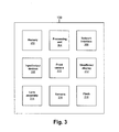
- Fig. 3 shows an exemplary block diagram of device 100 of Fig. 1A .
- device 100 may include memory 302, a processing unit 304, a network interface 306, input/output devices 308, a front camera 310, a viewfinder/display 312, a lens assembly 314, sensors 316, and a flash 318.
- a bus (not shown) may interconnect the components illustrated in Fig. 3 .
- device 100 may include more, fewer, or different components.
- device 100 may include film.
- Memory 302 may include static memory, such as read only memory (ROM), and/or dynamic memory, such as random access memory (RAM), or onboard cache, for storing data and machine-readable instructions. Memory 302 may also include storage devices, such as a floppy disk, CD ROM, CD read/write (R/W) disc, and/or flash memory, as well as other types of storage devices.
- Processing unit 304 may include one or more processors, microprocessors, and/or processing logic capable of controlling device 100.
- Network interface 306 may include any transceiver-like mechanism that enables device 100 to communicate with other devices and/or systems. For example, network interface 306 may include mechanisms for communicating via a network, such as the Internet, a terrestrial wireless network, a satellite-based network, etc.
- network interface 306 may include a modem, an Ethernet interface to a LAN, and/or an interface/ connection for connecting device 100 to other devices.
- Input/output devices 308 may include a keyboard, keypad (e.g., keypad 210 of Fig. 2A ), button (e.g., control buttons 208), mouse, speaker (e.g., speaker 204), microphone (e.g., microphone 212), Digital Video Disk (DVD) writer, DVD reader, Universal Serial Bus (USB) lines, and/or another type of device for converting physical events or phenomena to and/or from digital signals that pertain to device 100.
- keypad e.g., keypad 210 of Fig. 2A
- button e.g., control buttons 208
- mouse e.g., speaker 204
- microphone e.g., microphone 212
- DVD Digital Video Disk
- DVD Universal Serial Bus
- Front camera 310 may include devices to view, capture and store images (e.g., pictures, video clips) at device 100, and may provide image information to other components, such as memory 302, viewfinder/display 312, and/or sensors 316 for storage and for further processing.
- Viewfinder/display 312 may include a device that can display signals generated by device 100 as images on a screen and/or that can accept inputs in the form of taps or touches on the screen. For example, viewfinder/display 312 may provide a window through which the user may view images that are received from front camera 310 or lens assembly 314.
- viewfinder/display 312 examples include an optical viewfinder (e.g., a reversed telescope), a liquid crystal display (LCD), cathode ray tube (CRT) display, organic light-emitting diode (OLED) display, surface-conduction electron-emitter display (SED), plasma display, field emission display (FED), bistable display, and/or a touch screen.
- optical viewfinder e.g., a reversed telescope
- LCD liquid crystal display
- CRT cathode ray tube
- OLED organic light-emitting diode
- SED surface-conduction electron-emitter display
- FED field emission display
- bistable display e.g., a touch screen.
- Lens assembly 314 may include a device for manipulating light rays from a given or a selected range, so that images in the range can be captured in a desired manner. Lens assembly 314 may be controlled manually and/or electromechanically by processing unit 304 to obtain the correct focus and magnification (i. e., zoom) of the subject image and to provide a proper exposure. Sensors 316 may include one or more devices for obtaining information related to image, luminance, focus, and/or zoom. Sensors 316 may provide the information to processing unit 304, so that processing unit 304 may control lens assembly 314 and flash 318. Flash 318 may include any type of flash unit used in cameras.
- flash unit 318 may include a flash unit built into device 100; a flash unit separate from device 100; an electronic xenon flash lamp (e.g., a tube filled with xenon gas, where electricity of high voltage is discharged to generate an electrical arc that emits a short flash of light); or a microflash (e.g., a special, high-voltage flash unit designed to discharge a flash of light with a sub-microsecond duration).
- an electronic xenon flash lamp e.g., a tube filled with xenon gas, where electricity of high voltage is discharged to generate an electrical arc that emits a short flash of light
- a microflash e.g., a special, high-voltage flash unit designed to discharge a flash of light with a sub-microsecond duration.
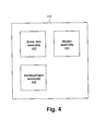
- Fig. 4 is an exemplary block diagram of lens assembly 314 of Fig. 3 .
- lens assembly 314 may include zoom lens assembly 402, shutter assembly 404, and iris/diaphragm assembly 406.
- lens assembly 314 may include more, fewer, or different components.
- Zoom lens assembly 402 may include a collection of lenses, and may provide a magnification and a focus of a given or selected image, by changing relative positions of the lenses.
- Shutter assembly 404 may include a device for allowing light to pass for a period of time.
- Shutter assembly 404 may expose sensors 316 to a determined amount of light to create an image of a view.
- Iris/diaphragm assembly 406 may include a device for providing an aperture for light and may control the brightness of light on sensors 316 by regulating the size of the aperture.
- Zoom lens assembly 402, shutter assembly 404, and iris/diaphragm assembly 406 may operate in conjunction with each other to provide a desired magnification and an exposure. For example, when a magnification is increased by using zoom lens assembly 402, shutter assembly 404 and iris/diaphragm assembly 406 may be adjusted to compensate for changes in the amount of light, in order to maintain the exposure relatively constant.
- Fig. 5 is an exemplary block diagram of sensors 316 of Fig. 3 .
- sensors 316 may include a light sensor 502, luminance sensor 504, focus sensor 506, and zoom sensor 508.
- sensors 316 may include additional, fewer, or different components.
- Light sensor 502 may include hardware and/or software for sensing light and storing an image.
- Luminance sensor 504 may include hardware and/or software for sensing the intensity of light (i.e., luminance) within a view.
- Luminance sensor 504 may provide luminance information that may be used for controlling flash 318 and the exposure of light sensor 502.
- An example of luminance sensor 504 includes a flash sensor.
- luminance sensor 504 may include a white point detector. The white point of a view may depend on light sources and may be used to white balance the view.
- Focus sensor 506 may include hardware and/or software for providing information that may be used for focusing an image.
- focus sensor 506 may provide the distance of a subject from device 100, so that device 100 may adjust lens assembly 314 to obtain a properly focused image of the subject.
- focus sensor 506 may detect when lens assembly 314 outputs an image with the greatest contrast between measured light intensities at adjacent detector elements in sensors 316 and indicate the focused condition.
- Zoom sensor 506 may include hardware and/or software for providing information about the distance between device 100 and a reference point. As illustrated in Fig. 1A , because the reference point may not be co-located with subject 102, focus sensor 506 may not necessarily provide to device 100 the information that zoom sensor 508 provides. That is, focus sensor 506 may provide distance information from device 100 to a subject, such as subject 102, for autofocusing purposes. In contrast, zoom sensor 508 may provide distance information, such as distance D in Fig. 1A , to device 100. This distance may be used to modify a displayed image, as described below.
- Fig. 6 is an exemplary block diagram of zoom sensor 508 of Fig. 5 .
- zoom sensor 508 may include accelerometer sensor 602, ultrasound sensor 604, and front camera image sensor 606.
- zoom sensor 508 may include fewer, additional, or different types of sensors.
- zoom sensor 508 may include an infrared sensor.
- zoom sensor 508 may include only accelerometer sensor 602 and exclude ultrasound sensor 604 and front camera image sensor 606.
- Accelerometer sensor 602 may include hardware and/or software for determining acceleration of device 100 and for determining changes in the distance between device 100 and a reference point. Accelerometer sensor 602 may include an accelerometer for obtaining values of acceleration of device 100.
- the accelerometer may include a device such as a micro electro mechanical system (MEMS) accelerometer or a piezoelectric accelerometer that is coupled to the housing of device 100. The changes in the distance between device 100 and a reference point may be determined in accordance with acceleration information obtained from the accelerometer.
- MEMS micro electro mechanical system
- Ultrasound sensor 604 may include hardware and/or software for determining the distance between a reference point and device 100 by measuring the difference between the time at which an ultrasound probe pulse is transmitted from device 100 and the time at which the echo pulse corresponding to the probe pulse is received by device 100.
- Front camera image sensor 606 may include hardware and/or software for measuring the distance between a reference point (e.g., the user's face, body, etc.) associated with an image to be captured and device 100, by using an effective focal distance of front camera lenses and a distance of a focused image from its lenses.
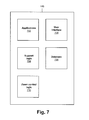
- Fig. 7 is an exemplary functional block diagram of exemplary components that may be included in the device of Fig. 1A .
- Device 100 may include applications 702, user interface 704, support logic 706, database 708, and zoom control logic 710. In other implementations, device 100 may include fewer, additional, or different types of components than those illustrated in Fig. 7 .
- Applications 702 may include hardware and/or software for supporting various functionalities of device 100, such as text messaging, email, Multimedia Messaging, wireless (e.g., Bluetooth) communications, image capturing and storing, infrared communications, web access, file uploading and downloading, image transfer, etc.
- wireless e.g., Bluetooth
- User interface 704 may include hardware and/or software for allowing a user to interact with applications 702, support logic 706, database 708, and/or zoom control logic 710.
- user interface 704 may accept inputs that indicate the start or the end of a zoom control and calibration parameters that specify how much to magnify a subject per unit of distance that device 100 has changed or moved with respect to a reference point. For example, a user may input calibration parameters that instruct device 100 to magnify an image 20% per 1 inch decrease in the distance.
- Support logic 706 may include hardware and/or software for performing various support functions for applications 702, user interface 704, database 708, and zoom control logic 710.
- support logic 706 may provide interfaces between the components illustrated in Fig. 7 (e.g., applications 702, zoom control logic 710) and the components in Fig. 3 (e.g., network interface 306, input/output devices 308, front camera 310, viewfinder/display 312, etc.).
- support logic 706 may provide a TCI/IP stack to support communication applications.
- Database 708 may act as an information repository for applications 702, user interface 704, support logic 706, and/or zoom control logic 710.
- applications 702 may store and/or retrieve captured images and/or sounds to and from database 708.
- user interface 704 may store accepted input values for controlling zoom at database 708.
- Zoom control logic 710 may include hardware and/or software that receive outputs from one or more of the subcomponents of zoom sensor 508 ( Fig. 5 ), for determining new zoom values based on the outputs and/or calibration parameters that have been inputted, and for controlling zoom lens assembly 402 ( Fig. 4 ) in accordance with the new zoom values. If a user has not supplied calibration parameters, default values may be used.
- zoom control logic 710 may begin to use or receive outputs from accelerometer sensor 602 ( Fig. 6 ) when a user signals zoom control logic 710, through one of input/output devices 308 ( Fig. 3 ) (e.g., control buttons 208, keypad 210, etc.). For example, when the user activates a camera mode of device 100, zoom control logic 710 may automatically begin processing data from accelerometer sensor 602. Zoom control logic 710 may use the outputs, which reflect the changes in the distance between device 100 and a reference point (e.g., the user) after the occurrence of the signal, to determine a new zoom for zoom lens assembly 402. Zoom control logic 710 may cause lens assembly 314 (i.e., zoom lens assembly 402, shutter assembly 404, and iris/diaphragm assembly 406) to adjust in accordance with the new zoom.
- lens assembly 314 i.e., zoom lens assembly 402, shutter assembly 404, and iris/diaphragm assembly 406
- zoom control logic 710 may use outputs from others components of zoom sensor 508, such as ultrasound sensor 604 or front camera image sensor 606, in the manner similar to that described above for accelerometer sensor 602.
- zoom sensor 508 may use the outputs from one or more of the accelerometer sensor 602, ultrasound sensor 604, or front camera image sensor 606 to determine a new zoom and adjust zoom lens assembly 402. In determining the new zoom, the outputs of the accelerometer sensor 602, ultrasound sensor 604, and/or front camera image sensor 606 may be averaged or may be used together to obtain a more accurate zoom value.
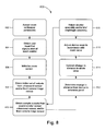
- Fig. 8 shows an exemplary process for controlling a zoom based on the distance between a reference point and the device of Fig. 1A .
- zoom calibration parameters may be accepted.
- a user may provide calibration parameters. If no calibration parameters are provided, default values may be used.
- a user input that signals the start of a zoom control may be obtained (e.g., clicking on one of control buttons 208 ( Fig. 2A ), activating a camera mode of device 100, etc.).
- zoom sensor 508 may be initialized. Initializing zoom sensor 508 may signal accelerometer sensor 602 to reset measurement values to zero and cause ultrasound sensor 604 and front camera image sensor 606 to determine the reference distance between a reference point (e.g., the user's body, the user's face, etc.) and device 100.
- a reference point e.g., the user's body, the user's face, etc.
- an initial set of outputs from ultrasound sensor 604 and/or front camera image sensor 606 may be obtained.
- the outputs may relate the initial distance between the reference point, such as a user, and device 100.
- sample outputs from accelerometer sensor 602, ultrasound sensor 604, and/or front camera image sensor 606 may be obtained.
- the sample outputs of accelerometer sensor 602 relate the change in the distance between the reference point and device 100 after initializing zoom sensor 508.
- the sample outputs of ultrasound sensor 604 or front camera image sensor 606 relate the current distance between the reference point and device 100.
- a change in distance from device 100 to the reference point may be determined.
- the change in distance from device 100 to the reference point may be the same as its output.
- the change in distance may be given by the difference between its output at block 810 and its initial output at block 808.
- the change in distance may be converted to a zoom value.
- the calibration parameters may also indicate that optical magnification of the image is to decrease 20% per 1 inch increase in the distance D in Fig. 1A .
- the zoom of device 100 may be adjusted in accordance with the zoom value.
- adjusting the zoom of device 100 may enlarge image 106 in Fig. 1B by 144%, to result in image 108 in Fig. 1C .
- shutter assembly 404 and iris/diaphragm assembly 406 may be adjusted to compensate for any changes in white balance, focus, and/or exposure due to changes in zoom.
- N 2 / t I S / K , where N measures the ratio of the focal distance of the lens to iris/diaphragm opening (i.e., relative aperture), t is the shutter speed, I is the average luminance, S is the sensitivity of film to light, and K is a calibration constant.
- the shutter speed and the aperture size may be adjusted in accordance with equation (1).
- adjusting the magnification may affect its focal distance, which in turn may affect N in equation (1).
- changing a view may affect the luminance, I .
- process 800 returns to 810, unless process 800 is terminated by the user through an input. That is, as the user moves device 100 closer and/or further from the reference point (e.g., his/her face, body, etc), zoom parameters may be determined and magnification of a subject displayed via display 206 ( Fig. 1A ) may be changed without requiring the user to manually adjust a zoom controller.
- the reference point e.g., his/her face, body, etc
- Figs. 9A and 9B are rear and front views, respectively, of another exemplary device in which the systems and methods described herein can be implemented.
- device 900 may take the form of a camera (e.g., a standard camera) with or without additional communication functionality, such as the ability to make or receive telephone calls.
- device 900 may include a button 902, a viewfinder 904, a lens assembly 906, sensors 908, a flash 910, and housing 912.
- Button 902, viewfinder 904, lens assembly 906, sensors 908, flash 910, and housing 912 may include components that are similar to control buttons 208, display 206, lens assembly 216, sensors 214, flash 218, and housing 220, and may operate similarly.
- device 900 may also include components that have been described with references to Figs. 2-7 .
- the following example illustrates processes involved in controlling optical zoom, with reference to Fig. 10A-C .
- the example is consistent with the exemplary process described above with reference to Figs. 8 .
- Fig. 10B illustrates image 1006 of bird 1002 on a display 1004 of her camera 1000. Finding the size of image 1006 too small, Brigitte decides to zoom in on bird 1002. She clicks on a control button (not shown) to begin zooming. Alternatively, camera 1000 may automatically begin zooming without input from Brigitte based on camera 1000 being activated (e.g., turned on).
- camera 1000 measures the distance from camera 1000 to Brigitte (i.e., reference point). As Brigitte pulls camera 1000 toward her body, camera 1000 continues to measure changes in the distance between camera 1000 and Brigitte, to determine zoom values, and to show images on display 1004 that are magnified in accordance with the zoom values. When Brigitte sees image 1008, as illustrated in Fig. 10C , Brigitte may decide to take a picture. Brigitte may also further adjust the size of image 1008 by moving camera 1000 away from her body or zoom in further by moving camera 1000 closer to her body. In this manner, simplified zoom control may be achieved by simply moving camera 1000.
- Brigitte i.e., reference point
- block 808 may be performed prior to block 806. If zoom sensor 508 includes only accelerometer sensor 602, block 808 and 810 may be omitted.
- non-dependent blocks may represent acts that can be performed in parallel to other blocks.
- logic that performs one or more functions.
- This logic may include hardware, such as a processor, an application specific integrated circuit, or a field programmable gate array, software, or a combination of hardware and software.
Landscapes
- Engineering & Computer Science (AREA)
- Multimedia (AREA)
- Signal Processing (AREA)
- Physics & Mathematics (AREA)
- General Physics & Mathematics (AREA)
- Studio Devices (AREA)
- Measurement Of Optical Distance (AREA)
- Automatic Focus Adjustment (AREA)
- Lens Barrels (AREA)
Abstract
Description
- Implementations described herein relate to photography and in particular, to controlling a zoom.
- When the size of a subject on the viewfinder of a camera is too small or too large, the optical zoom of the camera may be used to change the magnification of the subject image. The magnification may be changed by manually adjusting the zoom lens.
- According to one aspect, a method may comprise establishing a first distance between a device and a reference object, determining a difference between the first distance and a current distance between the device and the reference object, obtaining a zoom value based on the difference, and zooming in on a view based on the zoom value.
- Additionally, establishing a first distance may include setting an output value of an accelerometer sensor to zero.
- Additionally, determining the difference between the first distance and the current distance may include obtaining the output value from the accelerometer sensor.
- Additionally, the reference object may be a user of the device or a portion of the user's body.
- Additionally, the method may further comprise receiving a calibration value to be used for determining the zoom value.
- Additionally, obtaining a zoom value based on the difference may include multiplying the calibration value by the difference.
- Additionally, the method may further comprise setting a shutter speed or an aperture size based on the zoom value.
- Additionally, the method may further comprise setting a shutter speed, a white balance, or an aperture size based on luminance sensor outputs.
- Additionally, the method may further comprise focusing in on the view based on focus sensor outputs.
- Additionally, the method may further comprise receiving a user input to terminate zooming in on the view.
- Additionally, the method may further comprise capturing the view as an image.
- According to another aspect, a device may comprise a lens assembly and a sensor. Additionally, the device may further comprise a processor to set a reference position of the device relative to a reference point based on information from the sensor, determine the distance of the device to the reference position, derive zoom information based on the distance, and adjust the lens assembly to magnify an image based on the zoom information.
- Additionally, the sensor may include at least one of an accelerometer sensor that obtains the distance of the device to the reference position, an ultrasound sensor that obtains the distance of the device to the reference point, an infrared sensor that obtains the distance of the device to the reference point, or a camera sensor that obtains the distance of the device to the reference point.
- Additionally, the accelerometer sensor may include an accelerometer.
- Additionally, the camera sensor may include a video camera.
- Additionally, the device may further comprise a light sensor to sense the image, a memory to capture the image, and a display to show the image.
- Additionally, the sensor may include a luminance sensor for detecting brightness of the image.
- Additionally, the sensor may include a focus sensor.
- According to yet another aspect, a device may comprise means for obtaining a distance from the device to a user of the device, means for determining magnification based on the distance, and means for adjusting an optical zoom based on the magnification.
- Additionally, the device may further comprise at least one of means for measuring acceleration and determining the distance based on the measured acceleration, means for measuring a delay between an ultrasound pulse and an echo of the ultrasound pulse and determining the distance based on the delay, or means for measuring video camera parameters and determining the distance based on the video camera parameters.
- The accompanying drawings, which are incorporated in and constitute a part of this specification, illustrate one or more embodiments described herein and, together with the description, explain the embodiments. In the drawings,
-
Fig. 1A shows a person using a device to take a picture of a subject; -
Fig. 1B shows an image of the subject ofFig. 1A , at a zoom, on the display screen of the device ofFig. 1A ; -
Fig. 1C shows an image of the subject ofFig. 1A , at another zoom, on the display screen of the mobile device ofFig. 1A ; -
Figs. 2A and 2B are front and rear views, respectively, of the device ofFig. 1A ; -
Fig. 3 is an exemplary block diagram of the device ofFig. 1A ; -
Fig. 4 is an exemplary block diagram of the lens assembly ofFig. 3 ; -
Fig. 5 is an exemplary block diagram of the sensors ofFig. 3 ; -
Fig. 6 is an exemplary block diagram of the zoom sensor ofFig. 5 ; -
Fig. 7 is an exemplary functional block diagram of exemplary components that may be included in the device ofFig. 1A ; -
Fig. 8 illustrates an exemplary process for controlling a zoom based on the distance between a reference point and the device ofFig. 1A ; and -
Figs. 9A and 9B are rear and front views, respectively, of another exemplary device in which the systems and methods described herein can be implemented. - The following detailed description refers to the accompanying drawings. The same reference numbers in different drawings may identify the same or similar elements.
- The term "image," as used herein, may refer to a digital or an analog representation of visual information (e.g., a picture, a video, a photograph, animations, etc).
- The term "camera," as used herein, may include a device that may capture and store images. For example, a digital camera may include an electronic device that may capture and store images electronically instead of using photographic film. A digital camera may be multifunctional, with some devices capable of recording sound and/or images.
- A "subject," as the term is used herein, is to be broadly interpreted to include any person, place, and/or thing capable of being captured as an image.
- In the following implementations, the optical zoom of a device may be controlled by changing the distance between a reference point and the device.
Fig. 1A depicts aperson using device 100 to take a picture of a subject 102. InFig. 1B , animage 106 of subject 102 is shown ondisplay 104 ofdevice 100. If the person changes the distance D (Fig. 1A ) betweendevice 100 and a reference point (e.g., his face, his body, etc.), by pullingdevice 100 toward or away from the reference point,device 100 may detect the changes in distance D through its zoom sensor, use the detected changes to determine a new zoom value, and zoom in or out on subject 102 in accordance with the new zoom value.Fig. 1C showsimage 108 ondisplay 104 after zooming in on subject 102. By adjusting its zoom based on the distance between the reference point anddevice 100,device 100 allows its user to conveniently control the magnification of an image that is to be captured atdevice 100. -
Figs. 2A and 2B are front and rear views, respectively, ofdevice 100 ofFig. 1A . In this implementation,device 100 may be a mobile terminal capable of making and receiving telephone calls. As illustrated,device 100 may include afront camera 202, aspeaker 204, adisplay 206,control buttons 208, akeypad 210, amicrophone 212,sensors 214, alens assembly 216, aflash 218, andhousing 220.Front camera 202 may enable a user to view, capture and store images (e.g., pictures, video clips) of a subject in front ofdevice 100, and may be separate fromlens assembly 216 that is located on the back ofdevice 100.Speaker 204 may provide audible information to a user ofdevice 100.Display 206 may provide visual information to the user, such as video images or pictures.Control buttons 208 may permit the user to interact withdevice 100 to causedevice 100 to perform one or more operations, such as place or receive a telephone call.Keypad 210 may include a standard telephone keypad.Microphone 212 may receive audible information from the user.Sensors 214 may collect and provide, todevice 100, information (e.g., acoustic, infrared, etc.) that is used to aid the user in capturing images.Lens assembly 216, which is separate fromfront camera 202, may include a device for manipulating light rays from a given or a selected range, so that images in the range can be captured in a desired manner.Flash 218 may include any type of flash unit used in cameras and may provide illumination for taking pictures.Housing 220 may provide a casing for components ofdevice 100 and may protect the components from outside elements. -
Fig. 3 shows an exemplary block diagram ofdevice 100 ofFig. 1A . As shown,device 100 may includememory 302, aprocessing unit 304, anetwork interface 306, input/output devices 308, afront camera 310, a viewfinder/display 312, alens assembly 314,sensors 316, and aflash 318. A bus (not shown) may interconnect the components illustrated inFig. 3 . In other implementations,device 100 may include more, fewer, or different components. For example, whendevice 100 takes the form of a non-digital camera,device 100 may include film. -
Memory 302 may include static memory, such as read only memory (ROM), and/or dynamic memory, such as random access memory (RAM), or onboard cache, for storing data and machine-readable instructions.Memory 302 may also include storage devices, such as a floppy disk, CD ROM, CD read/write (R/W) disc, and/or flash memory, as well as other types of storage devices.Processing unit 304 may include one or more processors, microprocessors, and/or processing logic capable of controllingdevice 100.Network interface 306 may include any transceiver-like mechanism that enablesdevice 100 to communicate with other devices and/or systems. For example,network interface 306 may include mechanisms for communicating via a network, such as the Internet, a terrestrial wireless network, a satellite-based network, etc. Additionally or alternatively,network interface 306 may include a modem, an Ethernet interface to a LAN, and/or an interface/ connection for connectingdevice 100 to other devices. Input/output devices 308 may include a keyboard, keypad (e.g.,keypad 210 ofFig. 2A ), button (e.g., control buttons 208), mouse, speaker (e.g., speaker 204), microphone (e.g., microphone 212), Digital Video Disk (DVD) writer, DVD reader, Universal Serial Bus (USB) lines, and/or another type of device for converting physical events or phenomena to and/or from digital signals that pertain todevice 100. -
Front camera 310 may include devices to view, capture and store images (e.g., pictures, video clips) atdevice 100, and may provide image information to other components, such asmemory 302, viewfinder/display 312, and/orsensors 316 for storage and for further processing. Viewfinder/display 312 may include a device that can display signals generated bydevice 100 as images on a screen and/or that can accept inputs in the form of taps or touches on the screen. For example, viewfinder/display 312 may provide a window through which the user may view images that are received fromfront camera 310 orlens assembly 314. Examples of viewfinder/display 312 include an optical viewfinder (e.g., a reversed telescope), a liquid crystal display (LCD), cathode ray tube (CRT) display, organic light-emitting diode (OLED) display, surface-conduction electron-emitter display (SED), plasma display, field emission display (FED), bistable display, and/or a touch screen. -
Lens assembly 314 may include a device for manipulating light rays from a given or a selected range, so that images in the range can be captured in a desired manner.Lens assembly 314 may be controlled manually and/or electromechanically by processingunit 304 to obtain the correct focus and magnification (i. e., zoom) of the subject image and to provide a proper exposure.Sensors 316 may include one or more devices for obtaining information related to image, luminance, focus, and/or zoom.Sensors 316 may provide the information toprocessing unit 304, so that processingunit 304 may controllens assembly 314 andflash 318.Flash 318 may include any type of flash unit used in cameras. For example,flash unit 318 may include a flash unit built intodevice 100; a flash unit separate fromdevice 100; an electronic xenon flash lamp (e.g., a tube filled with xenon gas, where electricity of high voltage is discharged to generate an electrical arc that emits a short flash of light); or a microflash (e.g., a special, high-voltage flash unit designed to discharge a flash of light with a sub-microsecond duration). -
Fig. 4 is an exemplary block diagram oflens assembly 314 ofFig. 3 . As shown,lens assembly 314 may includezoom lens assembly 402,shutter assembly 404, and iris/diaphragm assembly 406. In other implementations,lens assembly 314 may include more, fewer, or different components. -
Zoom lens assembly 402 may include a collection of lenses, and may provide a magnification and a focus of a given or selected image, by changing relative positions of the lenses.Shutter assembly 404 may include a device for allowing light to pass for a period of time.Shutter assembly 404 may exposesensors 316 to a determined amount of light to create an image of a view. Iris/diaphragm assembly 406 may include a device for providing an aperture for light and may control the brightness of light onsensors 316 by regulating the size of the aperture. -
Zoom lens assembly 402,shutter assembly 404, and iris/diaphragm assembly 406 may operate in conjunction with each other to provide a desired magnification and an exposure. For example, when a magnification is increased by usingzoom lens assembly 402,shutter assembly 404 and iris/diaphragm assembly 406 may be adjusted to compensate for changes in the amount of light, in order to maintain the exposure relatively constant. -
Fig. 5 is an exemplary block diagram ofsensors 316 ofFig. 3 . As shown,sensors 316 may include alight sensor 502,luminance sensor 504, focus sensor 506, andzoom sensor 508. In another implementation,sensors 316 may include additional, fewer, or different components. -
Light sensor 502 may include hardware and/or software for sensing light and storing an image.Luminance sensor 504 may include hardware and/or software for sensing the intensity of light (i.e., luminance) within a view.Luminance sensor 504 may provide luminance information that may be used for controllingflash 318 and the exposure oflight sensor 502. An example ofluminance sensor 504 includes a flash sensor. In one implementation,luminance sensor 504 may include a white point detector. The white point of a view may depend on light sources and may be used to white balance the view. - Focus sensor 506 may include hardware and/or software for providing information that may be used for focusing an image. In one implementation, focus sensor 506 may provide the distance of a subject from
device 100, so thatdevice 100 may adjustlens assembly 314 to obtain a properly focused image of the subject. In another implementation, focus sensor 506 may detect whenlens assembly 314 outputs an image with the greatest contrast between measured light intensities at adjacent detector elements insensors 316 and indicate the focused condition. - Zoom sensor 506 may include hardware and/or software for providing information about the distance between
device 100 and a reference point. As illustrated inFig. 1A , because the reference point may not be co-located with subject 102, focus sensor 506 may not necessarily provide todevice 100 the information thatzoom sensor 508 provides. That is, focus sensor 506 may provide distance information fromdevice 100 to a subject, such as subject 102, for autofocusing purposes. In contrast,zoom sensor 508 may provide distance information, such as distance D inFig. 1A , todevice 100. This distance may be used to modify a displayed image, as described below. -
Fig. 6 is an exemplary block diagram ofzoom sensor 508 ofFig. 5 . As shown,zoom sensor 508 may includeaccelerometer sensor 602, ultrasound sensor 604, and frontcamera image sensor 606. In other implementations,zoom sensor 508 may include fewer, additional, or different types of sensors. For example, in one implementation,zoom sensor 508 may include an infrared sensor. In another example,zoom sensor 508 may includeonly accelerometer sensor 602 and exclude ultrasound sensor 604 and frontcamera image sensor 606. -
Accelerometer sensor 602 may include hardware and/or software for determining acceleration ofdevice 100 and for determining changes in the distance betweendevice 100 and a reference point.Accelerometer sensor 602 may include an accelerometer for obtaining values of acceleration ofdevice 100. The accelerometer may include a device such as a micro electro mechanical system (MEMS) accelerometer or a piezoelectric accelerometer that is coupled to the housing ofdevice 100. The changes in the distance betweendevice 100 and a reference point may be determined in accordance with acceleration information obtained from the accelerometer. - Ultrasound sensor 604 may include hardware and/or software for determining the distance between a reference point and
device 100 by measuring the difference between the time at which an ultrasound probe pulse is transmitted fromdevice 100 and the time at which the echo pulse corresponding to the probe pulse is received bydevice 100. Frontcamera image sensor 606 may include hardware and/or software for measuring the distance between a reference point (e.g., the user's face, body, etc.) associated with an image to be captured anddevice 100, by using an effective focal distance of front camera lenses and a distance of a focused image from its lenses. -
Fig. 7 is an exemplary functional block diagram of exemplary components that may be included in the device ofFig. 1A .Device 100 may includeapplications 702, user interface 704,support logic 706,database 708, and zoomcontrol logic 710. In other implementations,device 100 may include fewer, additional, or different types of components than those illustrated inFig. 7 . -
Applications 702 may include hardware and/or software for supporting various functionalities ofdevice 100, such as text messaging, email, Multimedia Messaging, wireless (e.g., Bluetooth) communications, image capturing and storing, infrared communications, web access, file uploading and downloading, image transfer, etc. - User interface 704 may include hardware and/or software for allowing a user to interact with
applications 702,support logic 706,database 708, and/or zoomcontrol logic 710. In one implementation, for controlling zoom, user interface 704 may accept inputs that indicate the start or the end of a zoom control and calibration parameters that specify how much to magnify a subject per unit of distance thatdevice 100 has changed or moved with respect to a reference point. For example, a user may input calibration parameters that instructdevice 100 to magnify an image 20% per 1 inch decrease in the distance. -
Support logic 706 may include hardware and/or software for performing various support functions forapplications 702, user interface 704,database 708, and zoomcontrol logic 710. For example,support logic 706 may provide interfaces between the components illustrated inFig. 7 (e.g.,applications 702, zoom control logic 710) and the components inFig. 3 (e.g.,network interface 306, input/output devices 308,front camera 310, viewfinder/display 312, etc.). In yet another example,support logic 706 may provide a TCI/IP stack to support communication applications. -
Database 708 may act as an information repository forapplications 702, user interface 704,support logic 706, and/or zoomcontrol logic 710. For example,applications 702 may store and/or retrieve captured images and/or sounds to and fromdatabase 708. In another example, user interface 704 may store accepted input values for controlling zoom atdatabase 708. -
Zoom control logic 710 may include hardware and/or software that receive outputs from one or more of the subcomponents of zoom sensor 508 (Fig. 5 ), for determining new zoom values based on the outputs and/or calibration parameters that have been inputted, and for controlling zoom lens assembly 402 (Fig. 4 ) in accordance with the new zoom values. If a user has not supplied calibration parameters, default values may be used. - In one implementation,
zoom control logic 710 may begin to use or receive outputs from accelerometer sensor 602 (Fig. 6 ) when a user signalszoom control logic 710, through one of input/output devices 308 (Fig. 3 ) (e.g.,control buttons 208,keypad 210, etc.). For example, when the user activates a camera mode ofdevice 100,zoom control logic 710 may automatically begin processing data fromaccelerometer sensor 602.Zoom control logic 710 may use the outputs, which reflect the changes in the distance betweendevice 100 and a reference point (e.g., the user) after the occurrence of the signal, to determine a new zoom forzoom lens assembly 402.Zoom control logic 710 may cause lens assembly 314 (i.e.,zoom lens assembly 402,shutter assembly 404, and iris/diaphragm assembly 406) to adjust in accordance with the new zoom. - In other implementations, zoom
control logic 710 may use outputs from others components ofzoom sensor 508, such as ultrasound sensor 604 or frontcamera image sensor 606, in the manner similar to that described above foraccelerometer sensor 602. In still other implementations,zoom sensor 508 may use the outputs from one or more of theaccelerometer sensor 602, ultrasound sensor 604, or frontcamera image sensor 606 to determine a new zoom and adjustzoom lens assembly 402. In determining the new zoom, the outputs of theaccelerometer sensor 602, ultrasound sensor 604, and/or frontcamera image sensor 606 may be averaged or may be used together to obtain a more accurate zoom value. -
Fig. 8 shows an exemplary process for controlling a zoom based on the distance between a reference point and the device ofFig. 1A . Atblock 802, zoom calibration parameters may be accepted. As described above, a user may provide calibration parameters. If no calibration parameters are provided, default values may be used. - At
block 804, a user input that signals the start of a zoom control may be obtained (e.g., clicking on one of control buttons 208 (Fig. 2A ), activating a camera mode ofdevice 100, etc.). - At
block 806,zoom sensor 508 may be initialized.Initializing zoom sensor 508 may signalaccelerometer sensor 602 to reset measurement values to zero and cause ultrasound sensor 604 and frontcamera image sensor 606 to determine the reference distance between a reference point (e.g., the user's body, the user's face, etc.) anddevice 100. - At
block 808, an initial set of outputs from ultrasound sensor 604 and/or frontcamera image sensor 606 may be obtained. The outputs may relate the initial distance between the reference point, such as a user, anddevice 100. - At
block 810, sample outputs fromaccelerometer sensor 602, ultrasound sensor 604, and/or frontcamera image sensor 606 may be obtained. The sample outputs ofaccelerometer sensor 602 relate the change in the distance between the reference point anddevice 100 after initializingzoom sensor 508. The sample outputs of ultrasound sensor 604 or frontcamera image sensor 606 relate the current distance between the reference point anddevice 100. - At
block 812, a change in distance fromdevice 100 to the reference point may be determined. Foraccelerometer sensor 602, the change in distance fromdevice 100 to the reference point may be the same as its output. For ultrasound sensor 604 or frontcamera image sensor 606, the change in distance may be given by the difference between its output atblock 810 and its initial output atblock 808. - At
block 814, the change in distance may be converted to a zoom value. The conversion may be obtained by multiplying the change in distance by the calibration value. For example, if the user inFig. 1A movesdevice 100 two inches closer to the user's body and the calibration value indicates that optical magnification of the image is to increase 20% per 1 inch decrease in the distance D (Fig. 1A ), the zoom value may be (100 + 20)2 % = 144%. The calibration parameters may also indicate that optical magnification of the image is to decrease 20% per 1 inch increase in the distance D inFig. 1A . - At
block 816, the zoom ofdevice 100 may be adjusted in accordance with the zoom value. In the same example described above, adjusting the zoom ofdevice 100 may enlargeimage 106 inFig. 1B by 144%, to result inimage 108 inFig. 1C . In some implementations,device 100 may be configured to decrease the size of the image whendevice 100 moves closer to the reference point, and increase the size of the image whendevice 100 moves further away, based on the user's preference. In this case, whendevice 100 is moved two inches closer to the user, the zoom value may be determined as (100 ― 20)2 % = 64%, and the image may be made smaller by 36%. - At
block 818,shutter assembly 404 and iris/diaphragm assembly 406 may be adjusted to compensate for any changes in white balance, focus, and/or exposure due to changes in zoom. - The relationship between the iris/diaphragm opening size and shutter speed (exposure time) may be given by:

- When a zoom and/or a view changes, the shutter speed and the aperture size may be adjusted in accordance with equation (1). Depending on the specific implementation of
zoom lens assembly 402, adjusting the magnification may affect its focal distance, which in turn may affect N in equation (1). In addition, changing a view may affect the luminance, I . - At
block 818,process 800 returns to 810, unlessprocess 800 is terminated by the user through an input. That is, as the user movesdevice 100 closer and/or further from the reference point (e.g., his/her face, body, etc), zoom parameters may be determined and magnification of a subject displayed via display 206 (Fig. 1A ) may be changed without requiring the user to manually adjust a zoom controller. -
Figs. 9A and 9B are rear and front views, respectively, of another exemplary device in which the systems and methods described herein can be implemented. In this implementation,device 900 may take the form of a camera (e.g., a standard camera) with or without additional communication functionality, such as the ability to make or receive telephone calls. As shown inFig. 9A ,device 900 may include abutton 902, aviewfinder 904, alens assembly 906,sensors 908, aflash 910, andhousing 912.Button 902,viewfinder 904,lens assembly 906,sensors 908,flash 910, andhousing 912 may include components that are similar to controlbuttons 208,display 206,lens assembly 216,sensors 214,flash 218, andhousing 220, and may operate similarly. While not shown,device 900 may also include components that have been described with references toFigs. 2-7 . - The following example illustrates processes involved in controlling optical zoom, with reference to
Fig. 10A-C . The example is consistent with the exemplary process described above with reference toFigs. 8 . - Assume that Brigitte is on her vacation at a beach. Brigitte, who has started rubbing some tanning lotion on her skin, notices a
bird 1002 and decides to take a picture ofbird 1002. Because her right hand is full of tanning lotion, Brigitte takes hercamera 1000 with her left hand.Fig. 10B illustratesimage 1006 ofbird 1002 on adisplay 1004 of hercamera 1000. Finding the size ofimage 1006 too small, Brigitte decides to zoom in onbird 1002. She clicks on a control button (not shown) to begin zooming. Alternatively,camera 1000 may automatically begin zooming without input from Brigitte based oncamera 1000 being activated (e.g., turned on). - In each case,
camera 1000 measures the distance fromcamera 1000 to Brigitte (i.e., reference point). As Brigitte pullscamera 1000 toward her body,camera 1000 continues to measure changes in the distance betweencamera 1000 and Brigitte, to determine zoom values, and to show images ondisplay 1004 that are magnified in accordance with the zoom values. When Brigitte seesimage 1008, as illustrated inFig. 10C , Brigitte may decide to take a picture. Brigitte may also further adjust the size ofimage 1008 by movingcamera 1000 away from her body or zoom in further by movingcamera 1000 closer to her body. In this manner, simplified zoom control may be achieved by simply movingcamera 1000. - The foregoing description of embodiments provides illustration, but is not intended to be exhaustive or to limit the embodiments to the precise form disclosed. Modifications and variations are possible in light of the above teachings or may be acquired from practice of the teachings.
- For example, while series of blocks have been described with regard to processes illustrated in
Fig. 8 , the order of the blocks may be modified in other implementations. For example, block 808 may be performed prior to block 806. Ifzoom sensor 508 includesonly accelerometer sensor 602, block 808 and 810 may be omitted. In addition, non-dependent blocks may represent acts that can be performed in parallel to other blocks. - It will be apparent that aspects described herein may be implemented in many different forms of software, firmware, and hardware in the implementations illustrated in the figures. The actual software code or specialized control hardware used to implement aspects should not be construed as limiting. Thus, the operation and behavior of the aspects were described without reference to the specific software code - it being understood that software and control hardware can be designed to implement the aspects based on the description herein.
- No element, act, or instruction used in the present application should be construed as critical or essential to the invention unless explicitly described as such. Also, as used herein, the article "a" is intended to include one or more items. Where only one item is intended, the term "one" or similar language is used. Further, the phrase "based on" is intended to mean "based, at least in part, on" unless explicitly stated otherwise.
- It should be emphasized that the term "comprises/comprising" when used in this specification is taken to specify the presence of stated features, integers, steps or components but does not preclude the presence or addition of one or more other features, integers, steps, components, or groups thereof.
- Further, certain portions of the invention have been described as "logic" that performs one or more functions. This logic may include hardware, such as a processor, an application specific integrated circuit, or a field programmable gate array, software, or a combination of hardware and software.
Claims (16)
- A method comprising:receiving, via a mobile terminal (100), a first image of a subject to be captured by the mobile terminal;establishing a distance (D) between the mobile terminal and a user of the mobile terminal where the user is different than the subject to he captured by the mobile terminal;determining a change in the distance between the mobile terminal and the user;obtaining a zoom value based on the determined change in the distance between the mobile terminal and the user;zooming on the subject based on the zoom value;setting at least one of a focus, a shutter speed and an aperture size, associated with the mobile terminal, based on the zoom value; anddisplaying a second image of the subject based on the zooming on the subject and setting the focus, the shutter speed, and the aperture size.
- The method of claim 1, where a portion of the user's body is used to establish the distance (D) and is used to determine the change in the distance.
- The method of claim 1, further comprising:receiving a calibration value to be used for determining the zoom value, where the calibration value includes a value that represents an amount to change the zoom value per unit of the determined change in the distance (D) between the mobile terminal (100) and the user.
- The method of claim 3, where obtaining a zoom value based on the determined change in the distance (D) between the mobile terminal (100) and the user includes:multiplying the calibration value by the determined change in the distance between the mobile terminal and the user.
- The method of claim 1, further comprising:receiving outputs from a luminance sensor provided in the mobile terminal (100); andsetting, based on the luminance sensor outputs, a white balance of the second image associated with the mobile terminal,where setting the shutter speed and the aperture size is further based on the luminance sensor outputs.
- The method of claim 1, further comprising:receiving outputs from a focus sensor (506) provided in the mobile terminal; and focusing in on the subject based on the focus sensor outputs.
- The method of claim 1, further comprising: receiving, from the user, an input to terminate zooming on the subject.
- The method of claim 7, further comprising:capturing the second image of the subject in response to receiving the input to terminate zooming on the subject.
- A computer-readable medium comprising computer executable code for executing the method of claims 1-8.
- A mobile terminal (100) comprising:a lens assembly (216, 314); anda processor (304) to:receive a first image of a subject to be captured by the mobile terminal,establish a distance (D) between the mobile terminal and a user of the mobile terminal where the user is different than the subject to be captured by the mobile terminal;determine a change in a distance (D) between the mobile terminal and the user, where the user is different than the subject to be captured by the mobile terminal,derive zoom information based on the determined change in the distance between the mobile terminal and the user;set at least one of a focus, a shutter speed and an aperture size, associated with the mobile terminal, based on the zoom information; anddisplay the magnified image of the subject.
- The mobile terminal of claim 10, further comprising:an ultrasonic sensor (604); andwherein the processor sets a reference position of the mobile terminal relative to a user of the mobile terminal based on information received from the ultrasonic sensor.
- The mobile terminal of claim 10, further comprising:an acceleration sensor (602); and
wherein the processor:receives, from the acceleration sensor, an acceleration value associated with the mobile terminal; andwherein the step of determining the change in a distance (D) between the mobile terminal and the user is based on the received acceleration value. - The mobile terminal of claim 10, wherein the processor adjusts the lens assembly to magnify the image of the subject based on at least one of the zoom information, the focus, the shutter speed, and the aperture size.
- The mobile terminal of claim 10, further comprising:a light sensor (502) to sense the image;a memory (302) to store the magnified image; anda display (104, 206, 312) to show the magnified image.
- The mobile terminal (100) of claim 10, further comprising:a luminance sensor (504) that detects a brightness of the image, where the processor (304) is further to set the shutter speed and the aperture size based on an output of the luminance sensor.
- The mobile terminal of claim 10, further comprising:a focus sensor (506), where the processor (304) is further to set the focus based on an output of the focus sensor.
Applications Claiming Priority (2)
| Application Number | Priority Date | Filing Date | Title |
|---|---|---|---|
| US11/692,260 US7639935B2 (en) | 2007-03-28 | 2007-03-28 | Zoom control |
| EP07826596A EP2132926B1 (en) | 2007-03-28 | 2007-09-28 | Zoom control |
Related Parent Applications (1)
| Application Number | Title | Priority Date | Filing Date |
|---|---|---|---|
| EP07826596.4 Division | 2007-09-28 |
Publications (2)
| Publication Number | Publication Date |
|---|---|
| EP2388990A1 true EP2388990A1 (en) | 2011-11-23 |
| EP2388990B1 EP2388990B1 (en) | 2013-10-23 |
Family
ID=39092135
Family Applications (2)
| Application Number | Title | Priority Date | Filing Date |
|---|---|---|---|
| EP11177887.4A Not-in-force EP2388990B1 (en) | 2007-03-28 | 2007-09-28 | Zoom control |
| EP07826596A Not-in-force EP2132926B1 (en) | 2007-03-28 | 2007-09-28 | Zoom control |
Family Applications After (1)
| Application Number | Title | Priority Date | Filing Date |
|---|---|---|---|
| EP07826596A Not-in-force EP2132926B1 (en) | 2007-03-28 | 2007-09-28 | Zoom control |
Country Status (5)
| Country | Link |
|---|---|
| US (1) | US7639935B2 (en) |
| EP (2) | EP2388990B1 (en) |
| CN (1) | CN101637018B (en) |
| AT (1) | ATE525852T1 (en) |
| WO (1) | WO2008117141A1 (en) |
Cited By (1)
| Publication number | Priority date | Publication date | Assignee | Title |
|---|---|---|---|---|
| WO2014105507A1 (en) * | 2012-12-28 | 2014-07-03 | Motorola Mobility Llc | Front camera face detection for rear camera zoom function |
Families Citing this family (59)
| Publication number | Priority date | Publication date | Assignee | Title |
|---|---|---|---|---|
| EP1983740A1 (en) * | 2007-04-16 | 2008-10-22 | STMicroelectronics (Research & Development) Limited | Image stabilisation method and apparatus |
| US20100296802A1 (en) * | 2009-05-21 | 2010-11-25 | John Andrew Davies | Self-zooming camera |
| JP5335571B2 (en) * | 2009-06-15 | 2013-11-06 | キヤノン株式会社 | Imaging device |
| JP5274388B2 (en) * | 2009-06-15 | 2013-08-28 | キヤノン株式会社 | Imaging device |
| CN101996021B (en) * | 2009-08-12 | 2013-02-13 | 幻音科技(深圳)有限公司 | Handheld electronic equipment and method for controlling display contents thereby |
| JP2011044064A (en) * | 2009-08-24 | 2011-03-03 | Nikon Corp | Image processing device and image processing program |
| US8301202B2 (en) * | 2009-08-27 | 2012-10-30 | Lg Electronics Inc. | Mobile terminal and controlling method thereof |
| TWI450012B (en) * | 2010-03-17 | 2014-08-21 | Fih Hong Kong Ltd | System and method for taking photos |
| US20110298887A1 (en) * | 2010-06-02 | 2011-12-08 | Maglaque Chad L | Apparatus Using an Accelerometer to Capture Photographic Images |
| CN102055844B (en) * | 2010-11-15 | 2013-05-15 | 惠州Tcl移动通信有限公司 | Method and mobile phone device for realizing camera shutter function through gesture recognition |
| WO2012073779A1 (en) * | 2010-12-01 | 2012-06-07 | Necカシオモバイルコミュニケーションズ株式会社 | Mobile terminal, image processing method and program |
| US8754831B2 (en) * | 2011-08-02 | 2014-06-17 | Microsoft Corporation | Changing between display device viewing modes |
| EP2706376A1 (en) * | 2012-09-07 | 2014-03-12 | Leica Geosystems AG | Laser tracker with hybrid imaging method for expanding measurement range |
| KR101983288B1 (en) * | 2012-11-22 | 2019-05-29 | 삼성전자주식회사 | Apparatus and method for controlling a shooting status in a portable device having a dual camera |
| US9654563B2 (en) | 2012-12-14 | 2017-05-16 | Biscotti Inc. | Virtual remote functionality |
| US9485459B2 (en) * | 2012-12-14 | 2016-11-01 | Biscotti Inc. | Virtual window |
| US9568713B2 (en) | 2013-01-05 | 2017-02-14 | Light Labs Inc. | Methods and apparatus for using multiple optical chains in parallel to support separate color-capture |
| CN103327256A (en) * | 2013-07-05 | 2013-09-25 | 上海斐讯数据通信技术有限公司 | System and method for adjusting view-finding interface display image of mobile terminal camera |
| US9374514B2 (en) | 2013-10-18 | 2016-06-21 | The Lightco Inc. | Methods and apparatus relating to a camera including multiple optical chains |
| US9549127B2 (en) | 2013-10-18 | 2017-01-17 | Light Labs Inc. | Image capture control methods and apparatus |
| US9423588B2 (en) | 2013-10-18 | 2016-08-23 | The Lightco Inc. | Methods and apparatus for supporting zoom operations |
| US9736365B2 (en) | 2013-10-26 | 2017-08-15 | Light Labs Inc. | Zoom related methods and apparatus |
| US9426365B2 (en) | 2013-11-01 | 2016-08-23 | The Lightco Inc. | Image stabilization related methods and apparatus |
| US9554031B2 (en) | 2013-12-31 | 2017-01-24 | Light Labs Inc. | Camera focusing related methods and apparatus |
| US10931866B2 (en) | 2014-01-05 | 2021-02-23 | Light Labs Inc. | Methods and apparatus for receiving and storing in a camera a user controllable setting that is used to control composite image generation performed after image capture |
| WO2015110363A1 (en) * | 2014-01-24 | 2015-07-30 | Sony Corporation | Camera with radar-based autofocus |
| US9979878B2 (en) * | 2014-02-21 | 2018-05-22 | Light Labs Inc. | Intuitive camera user interface methods and apparatus |
| US9507066B2 (en) | 2014-06-30 | 2016-11-29 | Microsoft Technology Licensing, Llc | Eyepiece for near eye display system |
| EP3164831A4 (en) | 2014-07-04 | 2018-02-14 | Light Labs Inc. | Methods and apparatus relating to detection and/or indicating a dirty lens condition |
| US10110794B2 (en) | 2014-07-09 | 2018-10-23 | Light Labs Inc. | Camera device including multiple optical chains and related methods |
| US20160070343A1 (en) * | 2014-09-09 | 2016-03-10 | Beijing Lenovo Software Ltd. | Information processing method and electronic device |
| WO2016061565A1 (en) | 2014-10-17 | 2016-04-21 | The Lightco Inc. | Methods and apparatus for using a camera device to support multiple modes of operation |
| US9823352B2 (en) * | 2014-10-31 | 2017-11-21 | Rockwell Automation Safety Ag | Absolute distance measurement for time-of-flight sensors |
| EP3235243A4 (en) | 2014-12-17 | 2018-06-20 | Light Labs Inc. | Methods and apparatus for implementing and using camera devices |
| US9544503B2 (en) | 2014-12-30 | 2017-01-10 | Light Labs Inc. | Exposure control methods and apparatus |
| CN104717427B (en) * | 2015-03-06 | 2018-06-08 | 广东欧珀移动通信有限公司 | A kind of automatic zooming method, device and mobile terminal |
| US9824427B2 (en) | 2015-04-15 | 2017-11-21 | Light Labs Inc. | Methods and apparatus for generating a sharp image |
| US9967535B2 (en) | 2015-04-17 | 2018-05-08 | Light Labs Inc. | Methods and apparatus for reducing noise in images |
| US9857584B2 (en) | 2015-04-17 | 2018-01-02 | Light Labs Inc. | Camera device methods, apparatus and components |
| US10075651B2 (en) | 2015-04-17 | 2018-09-11 | Light Labs Inc. | Methods and apparatus for capturing images using multiple camera modules in an efficient manner |
| US10091447B2 (en) | 2015-04-17 | 2018-10-02 | Light Labs Inc. | Methods and apparatus for synchronizing readout of multiple image sensors |
| US9930233B2 (en) | 2015-04-22 | 2018-03-27 | Light Labs Inc. | Filter mounting methods and apparatus and related camera apparatus |
| US10129483B2 (en) | 2015-06-23 | 2018-11-13 | Light Labs Inc. | Methods and apparatus for implementing zoom using one or more moveable camera modules |
| US10491806B2 (en) | 2015-08-03 | 2019-11-26 | Light Labs Inc. | Camera device control related methods and apparatus |
| US10397484B2 (en) * | 2015-08-14 | 2019-08-27 | Qualcomm Incorporated | Camera zoom based on sensor data |
| US10365480B2 (en) | 2015-08-27 | 2019-07-30 | Light Labs Inc. | Methods and apparatus for implementing and/or using camera devices with one or more light redirection devices |
| US10051182B2 (en) | 2015-10-05 | 2018-08-14 | Light Labs Inc. | Methods and apparatus for compensating for motion and/or changing light conditions during image capture |
| US9749549B2 (en) | 2015-10-06 | 2017-08-29 | Light Labs Inc. | Methods and apparatus for facilitating selective blurring of one or more image portions |
| CN105227845B (en) * | 2015-10-21 | 2018-01-16 | 广东欧珀移动通信有限公司 | Calibration method and system for laser focusing device of mobile terminal |
| US10003738B2 (en) | 2015-12-18 | 2018-06-19 | Light Labs Inc. | Methods and apparatus for detecting and/or indicating a blocked sensor or camera module |
| US10225445B2 (en) | 2015-12-18 | 2019-03-05 | Light Labs Inc. | Methods and apparatus for providing a camera lens or viewing point indicator |
| CN105744158B (en) * | 2016-02-03 | 2019-01-08 | 广东欧珀移动通信有限公司 | The method, device and mobile terminal that video image is shown |
| US10306218B2 (en) | 2016-03-22 | 2019-05-28 | Light Labs Inc. | Camera calibration apparatus and methods |
| CN106101532B (en) * | 2016-06-13 | 2019-12-10 | 惠州Tcl移动通信有限公司 | Method and system for adjusting camera focal length based on multifunctional keys on side edge of mobile terminal |
| CN106657766A (en) * | 2016-10-19 | 2017-05-10 | 广东欧珀移动通信有限公司 | Camera focus adjustment method, device and intelligent terminal |
| CN107392850B (en) * | 2017-06-30 | 2020-08-25 | 联想(北京)有限公司 | Image processing method and system |
| CN107633398A (en) * | 2017-08-24 | 2018-01-26 | 阿里巴巴集团控股有限公司 | Method for displaying image and device and electronic equipment |
| WO2022151473A1 (en) * | 2021-01-18 | 2022-07-21 | 深圳市大疆创新科技有限公司 | Photographing control method, photographing control apparatus and gimbal assembly |
| US12457301B2 (en) * | 2024-02-08 | 2025-10-28 | Lenovo (Singapore) Pte. Ltd. | Video processing adjustment based on user looking/not looking |
Citations (5)
| Publication number | Priority date | Publication date | Assignee | Title |
|---|---|---|---|---|
| EP1324597A2 (en) * | 2001-12-31 | 2003-07-02 | Nokia Corporation | Method and device for forming an image in an electronic device |
| JP2003195145A (en) * | 2001-12-27 | 2003-07-09 | Olympus Optical Co Ltd | camera |
| US20050122401A1 (en) * | 2003-10-15 | 2005-06-09 | Kenichi Horie | Camera |
| US20060077263A1 (en) * | 2004-09-29 | 2006-04-13 | Casio Computer Co., Ltd. | Method of capturing still image during capture of moving image and image capture apparatus |
| KR20060104606A (en) * | 2005-03-31 | 2006-10-09 | 주식회사 팬택 | Camera zoom control device based on distance of photographer and its method |
Family Cites Families (2)
| Publication number | Priority date | Publication date | Assignee | Title |
|---|---|---|---|---|
| JP2544964B2 (en) * | 1988-09-12 | 1996-10-16 | 富士写真フイルム株式会社 | Method for determining shutter speed in camera |
| US6420704B1 (en) | 2000-12-07 | 2002-07-16 | Trw Inc. | Method and system for improving camera infrared sensitivity using digital zoom |
-
2007
- 2007-03-28 US US11/692,260 patent/US7639935B2/en not_active Expired - Fee Related
- 2007-09-28 AT AT07826596T patent/ATE525852T1/en not_active IP Right Cessation
- 2007-09-28 WO PCT/IB2007/053967 patent/WO2008117141A1/en not_active Ceased
- 2007-09-28 CN CN2007800522809A patent/CN101637018B/en not_active Expired - Fee Related
- 2007-09-28 EP EP11177887.4A patent/EP2388990B1/en not_active Not-in-force
- 2007-09-28 EP EP07826596A patent/EP2132926B1/en not_active Not-in-force
Patent Citations (5)
| Publication number | Priority date | Publication date | Assignee | Title |
|---|---|---|---|---|
| JP2003195145A (en) * | 2001-12-27 | 2003-07-09 | Olympus Optical Co Ltd | camera |
| EP1324597A2 (en) * | 2001-12-31 | 2003-07-02 | Nokia Corporation | Method and device for forming an image in an electronic device |
| US20050122401A1 (en) * | 2003-10-15 | 2005-06-09 | Kenichi Horie | Camera |
| US20060077263A1 (en) * | 2004-09-29 | 2006-04-13 | Casio Computer Co., Ltd. | Method of capturing still image during capture of moving image and image capture apparatus |
| KR20060104606A (en) * | 2005-03-31 | 2006-10-09 | 주식회사 팬택 | Camera zoom control device based on distance of photographer and its method |
Cited By (1)
| Publication number | Priority date | Publication date | Assignee | Title |
|---|---|---|---|---|
| WO2014105507A1 (en) * | 2012-12-28 | 2014-07-03 | Motorola Mobility Llc | Front camera face detection for rear camera zoom function |
Also Published As
| Publication number | Publication date |
|---|---|
| EP2388990B1 (en) | 2013-10-23 |
| US20080240698A1 (en) | 2008-10-02 |
| WO2008117141A1 (en) | 2008-10-02 |
| CN101637018A (en) | 2010-01-27 |
| EP2132926B1 (en) | 2011-09-21 |
| EP2132926A1 (en) | 2009-12-16 |
| ATE525852T1 (en) | 2011-10-15 |
| CN101637018B (en) | 2011-09-14 |
| US7639935B2 (en) | 2009-12-29 |
Similar Documents
| Publication | Publication Date | Title |
|---|---|---|
| EP2132926B1 (en) | Zoom control | |
| EP2308226B1 (en) | Shadow and reflection identification in image capturing devices | |
| US7468743B2 (en) | Photographing device and method for obtaining photographic image having image vibration correction | |
| US20100302393A1 (en) | Self-portrait assistance in image capturing devices | |
| JP4873762B2 (en) | IMAGING DEVICE AND IMAGING DEVICE CONTROL METHOD | |
| JP5411508B2 (en) | Imaging apparatus and control method thereof | |
| JP2005321806A (en) | Image-exposure system and method | |
| JP5278564B2 (en) | Imaging device | |
| JP2001272591A (en) | Electronic still camera | |
| JP2019029998A (en) | IMAGING DEVICE, IMAGING DEVICE CONTROL METHOD, AND CONTROL PROGRAM | |
| KR101567814B1 (en) | METHOD, DEVICE, AND COMPUTER-READABLE STORAGE MEDIUM FOR PROVIDING SLIDE SHOW | |
| US7664383B2 (en) | Multiple frame photography | |
| JP2004234010A (en) | Camera showing focusing measure as function of focal distance | |
| TW200913680A (en) | Image stabilization with user feedback | |
| JP2015149611A (en) | Photographing apparatus, photographing support method, and photographing support program | |
| CN112088293A (en) | Computer-implemented method and system for preventing visual deterioration caused by long-term use of electronic visual display under dim light condition | |
| JP2002023241A (en) | Camera having focus information display function | |
| JP2010282107A (en) | Imaging apparatus and control method thereof | |
| JP2008076981A (en) | Electronic camera | |
| JP2016142853A (en) | Control device for imaging device | |
| JP2025173346A (en) | Image processing device, image processing method, and program | |
| KR101532611B1 (en) | Digital image processing apparatus and method showing zooming shot effect | |
| CN113709366A (en) | Information processing method and device | |
| JP2005062243A (en) | Camera | |
| JP2011040950A (en) | Imaging device, control method thereof, and program |
Legal Events
| Date | Code | Title | Description |
|---|---|---|---|
| AC | Divisional application: reference to earlier application |
Ref document number: 2132926 Country of ref document: EP Kind code of ref document: P |
|
| AK | Designated contracting states |
Kind code of ref document: A1 Designated state(s): AT BE BG CH CY CZ DE DK EE ES FI FR GB GR HU IE IS IT LI LT LU LV MC MT NL PL PT RO SE SI SK TR |
|
| PUAI | Public reference made under article 153(3) epc to a published international application that has entered the european phase |
Free format text: ORIGINAL CODE: 0009012 |
|
| 17P | Request for examination filed |
Effective date: 20120522 |
|
| 17Q | First examination report despatched |
Effective date: 20121109 |
|
| GRAP | Despatch of communication of intention to grant a patent |
Free format text: ORIGINAL CODE: EPIDOSNIGR1 |
|
| INTG | Intention to grant announced |
Effective date: 20130506 |
|
| GRAS | Grant fee paid |
Free format text: ORIGINAL CODE: EPIDOSNIGR3 |
|
| GRAA | (expected) grant |
Free format text: ORIGINAL CODE: 0009210 |
|
| AC | Divisional application: reference to earlier application |
Ref document number: 2132926 Country of ref document: EP Kind code of ref document: P |
|
| AK | Designated contracting states |
Kind code of ref document: B1 Designated state(s): AT BE BG CH CY CZ DE DK EE ES FI FR GB GR HU IE IS IT LI LT LU LV MC MT NL PL PT RO SE SI SK TR |
|
| REG | Reference to a national code |
Ref country code: GB Ref legal event code: FG4D |
|
| REG | Reference to a national code |
Ref country code: CH Ref legal event code: EP |
|
| REG | Reference to a national code |
Ref country code: AT Ref legal event code: REF Ref document number: 638115 Country of ref document: AT Kind code of ref document: T Effective date: 20131115 |
|
| REG | Reference to a national code |
Ref country code: IE Ref legal event code: FG4D |
|
| REG | Reference to a national code |
Ref country code: DE Ref legal event code: R096 Ref document number: 602007033529 Country of ref document: DE Effective date: 20131219 |
|
| REG | Reference to a national code |
Ref country code: NL Ref legal event code: T3 |
|
| REG | Reference to a national code |
Ref country code: NL Ref legal event code: T3 |
|
| REG | Reference to a national code |
Ref country code: AT Ref legal event code: MK05 Ref document number: 638115 Country of ref document: AT Kind code of ref document: T Effective date: 20131023 |
|
| REG | Reference to a national code |
Ref country code: LT Ref legal event code: MG4D |
|
| PG25 | Lapsed in a contracting state [announced via postgrant information from national office to epo] |
Ref country code: LT Free format text: LAPSE BECAUSE OF FAILURE TO SUBMIT A TRANSLATION OF THE DESCRIPTION OR TO PAY THE FEE WITHIN THE PRESCRIBED TIME-LIMIT Effective date: 20131023 Ref country code: SE Free format text: LAPSE BECAUSE OF FAILURE TO SUBMIT A TRANSLATION OF THE DESCRIPTION OR TO PAY THE FEE WITHIN THE PRESCRIBED TIME-LIMIT Effective date: 20131023 Ref country code: BE Free format text: LAPSE BECAUSE OF FAILURE TO SUBMIT A TRANSLATION OF THE DESCRIPTION OR TO PAY THE FEE WITHIN THE PRESCRIBED TIME-LIMIT Effective date: 20131023 Ref country code: FI Free format text: LAPSE BECAUSE OF FAILURE TO SUBMIT A TRANSLATION OF THE DESCRIPTION OR TO PAY THE FEE WITHIN THE PRESCRIBED TIME-LIMIT Effective date: 20131023 Ref country code: IS Free format text: LAPSE BECAUSE OF FAILURE TO SUBMIT A TRANSLATION OF THE DESCRIPTION OR TO PAY THE FEE WITHIN THE PRESCRIBED TIME-LIMIT Effective date: 20140223 |
|
| PG25 | Lapsed in a contracting state [announced via postgrant information from national office to epo] |
Ref country code: ES Free format text: LAPSE BECAUSE OF FAILURE TO SUBMIT A TRANSLATION OF THE DESCRIPTION OR TO PAY THE FEE WITHIN THE PRESCRIBED TIME-LIMIT Effective date: 20131023 Ref country code: CY Free format text: LAPSE BECAUSE OF FAILURE TO SUBMIT A TRANSLATION OF THE DESCRIPTION OR TO PAY THE FEE WITHIN THE PRESCRIBED TIME-LIMIT Effective date: 20131023 Ref country code: AT Free format text: LAPSE BECAUSE OF FAILURE TO SUBMIT A TRANSLATION OF THE DESCRIPTION OR TO PAY THE FEE WITHIN THE PRESCRIBED TIME-LIMIT Effective date: 20131023 Ref country code: LV Free format text: LAPSE BECAUSE OF FAILURE TO SUBMIT A TRANSLATION OF THE DESCRIPTION OR TO PAY THE FEE WITHIN THE PRESCRIBED TIME-LIMIT Effective date: 20131023 |
|
| PG25 | Lapsed in a contracting state [announced via postgrant information from national office to epo] |
Ref country code: PT Free format text: LAPSE BECAUSE OF FAILURE TO SUBMIT A TRANSLATION OF THE DESCRIPTION OR TO PAY THE FEE WITHIN THE PRESCRIBED TIME-LIMIT Effective date: 20140224 |
|
| REG | Reference to a national code |
Ref country code: DE Ref legal event code: R097 Ref document number: 602007033529 Country of ref document: DE |
|
| PG25 | Lapsed in a contracting state [announced via postgrant information from national office to epo] |
Ref country code: EE Free format text: LAPSE BECAUSE OF FAILURE TO SUBMIT A TRANSLATION OF THE DESCRIPTION OR TO PAY THE FEE WITHIN THE PRESCRIBED TIME-LIMIT Effective date: 20131023 |
|
| PG25 | Lapsed in a contracting state [announced via postgrant information from national office to epo] |
Ref country code: PL Free format text: LAPSE BECAUSE OF FAILURE TO SUBMIT A TRANSLATION OF THE DESCRIPTION OR TO PAY THE FEE WITHIN THE PRESCRIBED TIME-LIMIT Effective date: 20131023 Ref country code: CZ Free format text: LAPSE BECAUSE OF FAILURE TO SUBMIT A TRANSLATION OF THE DESCRIPTION OR TO PAY THE FEE WITHIN THE PRESCRIBED TIME-LIMIT Effective date: 20131023 Ref country code: IT Free format text: LAPSE BECAUSE OF FAILURE TO SUBMIT A TRANSLATION OF THE DESCRIPTION OR TO PAY THE FEE WITHIN THE PRESCRIBED TIME-LIMIT Effective date: 20131023 Ref country code: SK Free format text: LAPSE BECAUSE OF FAILURE TO SUBMIT A TRANSLATION OF THE DESCRIPTION OR TO PAY THE FEE WITHIN THE PRESCRIBED TIME-LIMIT Effective date: 20131023 Ref country code: RO Free format text: LAPSE BECAUSE OF FAILURE TO SUBMIT A TRANSLATION OF THE DESCRIPTION OR TO PAY THE FEE WITHIN THE PRESCRIBED TIME-LIMIT Effective date: 20131023 |
|
| PLBE | No opposition filed within time limit |
Free format text: ORIGINAL CODE: 0009261 |
|
| STAA | Information on the status of an ep patent application or granted ep patent |
Free format text: STATUS: NO OPPOSITION FILED WITHIN TIME LIMIT |
|
| PG25 | Lapsed in a contracting state [announced via postgrant information from national office to epo] |
Ref country code: DK Free format text: LAPSE BECAUSE OF FAILURE TO SUBMIT A TRANSLATION OF THE DESCRIPTION OR TO PAY THE FEE WITHIN THE PRESCRIBED TIME-LIMIT Effective date: 20131023 |
|
| 26N | No opposition filed |
Effective date: 20140724 |
|
| REG | Reference to a national code |
Ref country code: DE Ref legal event code: R097 Ref document number: 602007033529 Country of ref document: DE Effective date: 20140724 |
|
| PG25 | Lapsed in a contracting state [announced via postgrant information from national office to epo] |
Ref country code: SI Free format text: LAPSE BECAUSE OF FAILURE TO SUBMIT A TRANSLATION OF THE DESCRIPTION OR TO PAY THE FEE WITHIN THE PRESCRIBED TIME-LIMIT Effective date: 20131023 |
|
| PG25 | Lapsed in a contracting state [announced via postgrant information from national office to epo] |
Ref country code: LU Free format text: LAPSE BECAUSE OF FAILURE TO SUBMIT A TRANSLATION OF THE DESCRIPTION OR TO PAY THE FEE WITHIN THE PRESCRIBED TIME-LIMIT Effective date: 20140928 Ref country code: MC Free format text: LAPSE BECAUSE OF FAILURE TO SUBMIT A TRANSLATION OF THE DESCRIPTION OR TO PAY THE FEE WITHIN THE PRESCRIBED TIME-LIMIT Effective date: 20131023 |
|
| REG | Reference to a national code |
Ref country code: CH Ref legal event code: PL |
|
| GBPC | Gb: european patent ceased through non-payment of renewal fee |
Effective date: 20140928 |
|
| REG | Reference to a national code |
Ref country code: FR Ref legal event code: ST Effective date: 20150529 |
|
| REG | Reference to a national code |
Ref country code: IE Ref legal event code: MM4A |
|
| PG25 | Lapsed in a contracting state [announced via postgrant information from national office to epo] |
Ref country code: CH Free format text: LAPSE BECAUSE OF NON-PAYMENT OF DUE FEES Effective date: 20140930 Ref country code: LI Free format text: LAPSE BECAUSE OF NON-PAYMENT OF DUE FEES Effective date: 20140930 Ref country code: GB Free format text: LAPSE BECAUSE OF NON-PAYMENT OF DUE FEES Effective date: 20140928 |
|
| PG25 | Lapsed in a contracting state [announced via postgrant information from national office to epo] |
Ref country code: IE Free format text: LAPSE BECAUSE OF NON-PAYMENT OF DUE FEES Effective date: 20140928 Ref country code: FR Free format text: LAPSE BECAUSE OF NON-PAYMENT OF DUE FEES Effective date: 20140930 |
|
| PGFP | Annual fee paid to national office [announced via postgrant information from national office to epo] |
Ref country code: DE Payment date: 20150922 Year of fee payment: 9 |
|
| PGFP | Annual fee paid to national office [announced via postgrant information from national office to epo] |
Ref country code: NL Payment date: 20150909 Year of fee payment: 9 |
|
| PG25 | Lapsed in a contracting state [announced via postgrant information from national office to epo] |
Ref country code: BG Free format text: LAPSE BECAUSE OF FAILURE TO SUBMIT A TRANSLATION OF THE DESCRIPTION OR TO PAY THE FEE WITHIN THE PRESCRIBED TIME-LIMIT Effective date: 20131023 |
|
| PG25 | Lapsed in a contracting state [announced via postgrant information from national office to epo] |
Ref country code: MT Free format text: LAPSE BECAUSE OF FAILURE TO SUBMIT A TRANSLATION OF THE DESCRIPTION OR TO PAY THE FEE WITHIN THE PRESCRIBED TIME-LIMIT Effective date: 20131023 Ref country code: GR Free format text: LAPSE BECAUSE OF FAILURE TO SUBMIT A TRANSLATION OF THE DESCRIPTION OR TO PAY THE FEE WITHIN THE PRESCRIBED TIME-LIMIT Effective date: 20140124 |
|
| PG25 | Lapsed in a contracting state [announced via postgrant information from national office to epo] |
Ref country code: TR Free format text: LAPSE BECAUSE OF FAILURE TO SUBMIT A TRANSLATION OF THE DESCRIPTION OR TO PAY THE FEE WITHIN THE PRESCRIBED TIME-LIMIT Effective date: 20131023 Ref country code: HU Free format text: LAPSE BECAUSE OF FAILURE TO SUBMIT A TRANSLATION OF THE DESCRIPTION OR TO PAY THE FEE WITHIN THE PRESCRIBED TIME-LIMIT; INVALID AB INITIO Effective date: 20070928 |
|
| REG | Reference to a national code |
Ref country code: DE Ref legal event code: R119 Ref document number: 602007033529 Country of ref document: DE |
|
| REG | Reference to a national code |
Ref country code: NL Ref legal event code: MM Effective date: 20161001 |
|
| PG25 | Lapsed in a contracting state [announced via postgrant information from national office to epo] |
Ref country code: NL Free format text: LAPSE BECAUSE OF NON-PAYMENT OF DUE FEES Effective date: 20161001 |
|
| PG25 | Lapsed in a contracting state [announced via postgrant information from national office to epo] |
Ref country code: DE Free format text: LAPSE BECAUSE OF NON-PAYMENT OF DUE FEES Effective date: 20170401 |