EP2388541B1 - Flow path switching valve - Google Patents
Flow path switching valve Download PDFInfo
- Publication number
- EP2388541B1 EP2388541B1 EP11154126.4A EP11154126A EP2388541B1 EP 2388541 B1 EP2388541 B1 EP 2388541B1 EP 11154126 A EP11154126 A EP 11154126A EP 2388541 B1 EP2388541 B1 EP 2388541B1
- Authority
- EP
- European Patent Office
- Prior art keywords
- valve
- sub
- valve chamber
- pressure
- switching
- Prior art date
- Legal status (The legal status is an assumption and is not a legal conclusion. Google has not performed a legal analysis and makes no representation as to the accuracy of the status listed.)
- Active
Links
- 239000003507 refrigerant Substances 0.000 claims description 42
- 238000012856 packing Methods 0.000 claims description 26
- 238000000638 solvent extraction Methods 0.000 claims description 2
- 238000005057 refrigeration Methods 0.000 description 7
- CURLTUGMZLYLDI-UHFFFAOYSA-N Carbon dioxide Chemical compound O=C=O CURLTUGMZLYLDI-UHFFFAOYSA-N 0.000 description 5
- 238000007789 sealing Methods 0.000 description 5
- 229910002092 carbon dioxide Inorganic materials 0.000 description 4
- 238000001816 cooling Methods 0.000 description 3
- 238000010438 heat treatment Methods 0.000 description 3
- 239000002184 metal Substances 0.000 description 3
- 238000000034 method Methods 0.000 description 3
- 230000008569 process Effects 0.000 description 3
- OHMHBGPWCHTMQE-UHFFFAOYSA-N 2,2-dichloro-1,1,1-trifluoroethane Chemical compound FC(F)(F)C(Cl)Cl OHMHBGPWCHTMQE-UHFFFAOYSA-N 0.000 description 2
- 230000000694 effects Effects 0.000 description 2
- 238000012986 modification Methods 0.000 description 2
- 230000004048 modification Effects 0.000 description 2
- 230000000149 penetrating effect Effects 0.000 description 2
- 230000009467 reduction Effects 0.000 description 2
- 238000001179 sorption measurement Methods 0.000 description 2
- 230000000903 blocking effect Effects 0.000 description 1
- 239000001569 carbon dioxide Substances 0.000 description 1
- 239000007788 liquid Substances 0.000 description 1
- 239000000463 material Substances 0.000 description 1
- 230000007246 mechanism Effects 0.000 description 1
- 238000000465 moulding Methods 0.000 description 1
- 229920003002 synthetic resin Polymers 0.000 description 1
- 239000000057 synthetic resin Substances 0.000 description 1
- 238000003466 welding Methods 0.000 description 1
Images



Classifications
-
- F—MECHANICAL ENGINEERING; LIGHTING; HEATING; WEAPONS; BLASTING
- F25—REFRIGERATION OR COOLING; COMBINED HEATING AND REFRIGERATION SYSTEMS; HEAT PUMP SYSTEMS; MANUFACTURE OR STORAGE OF ICE; LIQUEFACTION SOLIDIFICATION OF GASES
- F25B—REFRIGERATION MACHINES, PLANTS OR SYSTEMS; COMBINED HEATING AND REFRIGERATION SYSTEMS; HEAT PUMP SYSTEMS
- F25B41/00—Fluid-circulation arrangements
- F25B41/20—Disposition of valves, e.g. of on-off valves or flow control valves
- F25B41/26—Disposition of valves, e.g. of on-off valves or flow control valves of fluid flow reversing valves
Definitions
- the present invention relates to a flow path switching valve for switching a flow path of a refrigerant used in a refrigeration cycle of an air conditioner or the like.
- Such a flow path switching valve is disclosed in JP, A, 2009-68695 (Patent document 1).
- a piston main body formed by joining two pistons and a main valve body is received in a tubular valve housing (valve main body), and the main valve body is slid relative to a valve seat in the valve housing in an axial direction to switch the flow path of the refrigerant passing though a plurality of pipes.
- a differential pressure between a pressure of the refrigerant in a main valve chamber between two pistons and a pressure of the refrigerant of a sub valve chamber outside of the pistons moves the piston main body.
- a second valve body (ball) disposed at the piston is in contact with the valve seat provided at an end cap of the valve housing, and by blocking an exhaust pipe provided at the valve seat, the pressures of the main valve chamber at a high pressure side and of the sub valve chamber at a low pressure side are equalized to reduce the differential pressure acting on a packing of the piston. In this way, even when a super high pressure refrigerant such as CO 2 is used, durability of the piston is maintained.
- a circular slope portion is provided around a packing of the piston.
- a sectional shape of the slope portion is gradually closer to an inner wall of the valve housing as the slope portion extends to an end of the valve housing.
- An object of the present invention is to solve the above-described problem, and to surely equalize the pressure between the main valve chamber and the sub valve chamber after the main valve body is moved, and improve the durability of the piston, in the flow path switching valve receiving two pistons and the main valve body in a joint manner in the tubular valve housing for switching the flow path of the refrigerant passing through a plurality of pipes by sliding the main valve body relative to the valve seat due to the differential pressure of the refrigerant between the main valve chamber inside the piston and the sub valve chamber outside the piston.
- a flow path switching valve for switching a flow of a refrigerant receiving two pistons joined together in a tubular valve housing disposed on an axial line of the valve housing, said two pistons partitioning the valve housing into a center main valve chamber to which a high pressure pipe is connected and two sub valve chambers at both sides of the main valve chamber, wherein a main valve seat connected to a low pressure pipe and two switching pipes is disposed in the main valve chamber, and a main valve body slidable in the axial direction relative to the main valve seat is connected to the piston, wherein by introducing a high pressure refrigerant into any one of the two sub valve chambers, and by reducing a pressure of the other sub valve chamber, the piston and the main valve body are moved to the sub valve chamber side due to a differential pressure between the sub valve chamber of which pressure is reduced and the main valve chamber, whereby with a concave portion of the valve body, the low pressure pipe alternatively communicates with any one of the
- the piston includes a packing contacting an inner wall of the valve housing, and a sloped portion extending circularly at the center of the valve housing is formed on an outer periphery of the packing. Further, a sectional shape of the sloped portion is gradually closer to the inner wall of the valve housing as the sloped portion extends toward the center of the valve housing.
- the flow path switching valve of the present invention when the piston finishes moving to the sub valve chamber of which pressure is reduced, the sub valve of the piston closes the opening of the sub valve seat at the sub valve chamber side. Therefore, the reduction of the pressure in the sub valve chamber is stopped, and the sub valve seat abuts on the sub valve to open the pressure equalizing path, thereby the refrigerant flows from the main valve chamber to the sub valve chamber via the pressure equalizing path.
- the differential pressure between the main valve chamber and the sub valve chamber is equalized smoothly.
- a pressure load acting on a sealing member of the piston is eliminated when the piston is not moved, a creep deformation of the sealing member is prevented. Further, a stress deformation of a member composing the piston is prevented. Accordingly, the flow path switching valve of the present invention is particularly suitable for a super high pressure refrigerant such as CO 2 refrigerant.
- the preferable flow path switching valve of the present invention in addition to the effect described above, when the pressure of the sub valve chamber is reduced, the high pressure refrigerant at the main valve chamber presses the sloped portion of the packing of the piston positioned between the pressure-reduced sub valve chamber and the high pressure main valve chamber toward the inner wall of the valve housing. Therefore, this packing can surely seal the pressure-reduced sub valve chamber and the main valve chamber, and the piston and the main valve body is surely moved.
- FIG. 1 is a schematic view showing a flow path switching valve, a pilot valve, and a refrigeration cycle according to the embodiment.
- a flow path switching valve 10 of this embodiment is a four way switching valve. This flow path switching valve 10 is connected to a pilot valve 20 with a pipe.
- a valve housing 1 is a tubular shape, and composed of a cylindrical cylinder 11 and two disk-shaped caps 12, 12. The caps 12, 12 are attached to the cylinder 11 by welding or the like so as to close ends of the cylinder 11.
- a center axis of the cylinder 11 and the caps 12, 12 is an axis line L1 of the valve housing 1.
- Thin circular concavities 121 are formed at the cylinder 11 side of the caps 12, 12.
- valve housing 1 Two pistons 2, 2 disposed on the axis line L of the valve housing 1 and joined together with a joining member 3 are received in the valve housing 1.
- an inside of the valve housing 1 composed of an inside of the cylinder 11 and circular concavities 121, 121 of the caps 12, 12 is partitioned by the two pistons 2, 2 into a center main valve chamber 11A and two sub valve chambers 12A, 12A disposed at both sides of the main valve chamber 11A.
- a main valve seat 4 is disposed at the center of the main valve chamber 11A, and a main valve body 5 sliding in the axis line L1 direction of the valve housing 1 is disposed on the main valve seat 4.
- E port 4a, S port 4b, and C port 4c arranged in a straight line in the axis line L1 direction of the valve housing 1 are formed in the main valve seat 4.
- E joint pipe 13a, S joint pipe 13b, C joint pipe 13c are respectively attached to E port 4a, S port 4b, and C port 4c.
- D port 11a is formed at a position facing the main valve seat 4 disposed at the center of the cylinder 11.
- D joint pipe 13d is attached to D port 11a.
- E joint pipe 13a and C joint pipe 13c correspond to a switching pipe
- S joint pipe 13b corresponds to a low pressure pipe
- D joint pipe 13d corresponds to a high pressure pipe.
- the main valve chamber 11A is connected to D joint pipe 13d as the high pressure pipe
- the main valve seat 4 is connected to the low pressure pipe and two switching pipes.
- a valve body fitting hole 3a is formed at the center of the joining member 3, and transparent holes 3b, 3c are formed at both sides of the valve body fitting hole 3a.
- the main valve body 5 is fitted into the valve body fitting hole 3a, and held with a little play in the axial line L direction relative to the joining member 3.
- the main valve body 5 is slid on the main valve seat 4 together with the joining member 3 and stopped at one of predetermined left or right positions.
- the main valve body 5 is made by insert-molding a bowl-shaped metal plate 51 with a resin-made member 52.
- a main valve concavity 5A is formed on an inside of the metal plate 51.
- the main valve body 5 communicates the S port 4b and the E port 4a via the main valve concavity 5A at a left end position shown in Fig. 1 .
- the C port 4c is communicated with the D port 11a mainly via the transparent hole 3c in the main valve chamber 11A.
- the main valve body 5 communicates the S port 4b and the C port 4c via the main valve concavity 5A at a right end position in Fig. 1 .
- the E port 4a is communicated with the D port 11a mainly via the transparent hole 3b in the main valve chamber 11A.
- the S joint pipe 13b is connected to an inlet of a compressor 30 via a low pressure pipe 14a, and the D joint pipe 13d is connected to an outlet of the compressor 30 via a high pressure pipe 14b.
- the C joint pipe 13c is connected to an indoor unit 50 via a pipe 14c, and the E joint pipe 13a is connected to an outdoor unit 40 via a pipe 14d.
- the outdoor unit 40 and the indoor unit 50 are connected to each other with a pipe 14e via a throttle unit 60.
- the refrigeration cycle is formed by a route composed of the C joint pipe 13c, the outdoor unit 40, the throttle unit 60, the indoor unit 50, and the E joint pipe 13a, and by a route composed of the S joint pipe 13b, the compressor 30, and the D joint pipe 13d.
- the pilot valve 20 switches the position of the main valve body 5 of the flow path switching valve 10 as described later.
- the high pressure refrigerant compressed by the compressor 30 flows from the D joint pipe 13d via the D port 11a to the main valve chamber 11A, and in a cooling operation of Fig. 1 , the high pressure refrigerant flows from the C port 4c to the outdoor unit 40. Further, in a heating operation when the main valve body 5 is switched, the high pressure refrigerant flows from the E port 4a to the indoor unit 50.
- the refrigerant discharged from the compressor 30 is circulated from the C joint pipe 13c via the outdoor unit 40, the throttle unit 60, the indoor unit 50, to the E joint pipe 13a.
- the outdoor unit 40 works as a condenser
- the indoor unit 50 works as an evaporator to cool the air. Further, in the heating operation, the refrigerant is circulated inversely.
- the indoor unit 50 works as the condenser
- the outdoor unit 40 works as the evaporator to heat the air.
- a sub valve seat 122 projected toward an inside of the cylinder 11 at the center of the circular concavity 121 (on the axial line L1) is formed on each of caps 12, 12. Further, an exhaust path 12a penetrating from a side of the cap 12 to an end 122a of the sub valve seat 122 is formed on each of caps 12, 12. Guiding pipes 15f, 15g are respectively connected to the exhaust paths 12a, 12a.
- the pilot valve 20 includes two electromagnetic actuators.
- This pilot valve 20 has a block-shaped valve housing 61, and two plunger cases 62, 62 are air-tightly fixed to the valve housing 61.
- adsorbers 63, 63 are air-tightly fixed to ends of the plunger cases 62, 62.
- a plunger 65 is disposed in the plunger cases 12, 12.
- Electromagnet coils 72, 72 wound around bobbins 71, 71 are disposed on outer peripheries of the adsorbers 63, 63 and the plunger cases 62, 62. When the electromagnet coils 72, 72 are excited, an inner end wall of the adsorber 63 becomes a magnetic adsorption surface relative to the plunger 65.
- a high pressure joint pipe 64d, a low pressure joint pipe 64b, and two switching joint pipes 64a, 64c are attached to the valve housing 61.
- the high pressure joint pipe 64d is connected to the D joint pipe 13d of the four way switching valve 10 by a guiding pipe 14f
- the low pressure joint pipe 64b is connected to the S joint pipe 13b of the four way switching valve 10 by a guiding pipe 14g.
- the switching joint pipes 64a, 64c are respectively connected to guiding pipes 15f, 15g of the four way switching valve 10.
- the high pressure joint pipe 64d, the low pressure joint pipe 64b, the switching joint pipes 64a, 64c, and the guiding pipes 14f, 14g, 14h, 14i can be made by the same material.
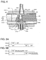
- Fig. 4 is a sectional view showing in detail a main part of the pilot valve 20.
- a cylindrical pilot valve chamber 61A is formed in the valve housing 61.
- the plunger cases 62, 62 are fitted into both ends of the pilot valve chamber 61A coaxially with an axial line L2.
- the plunger cases 62, 62 are a cylindrical shape.
- a pilot valve seat 66 is attached between the plunger cases 62, 62 in the pilot valve chamber 61A.
- a pilot valve body 67 sliding in an axial line L2 direction is provided on the pilot valve seat 66.
- a pilot switching port 61a, a pilot low pressure port 61b, and a pilot switching port 61c are arranged in a line in the axial line L2 direction in the pilot valve seat 66.
- the switching joint pipe 64a, the low pressure joint pipe 64b, and the switching joint pipe 64c are respectively attached to the pilot switching port 61a, the pilot low pressure port 61b, and the pilot switching port 61c. Further, a pilot high pressure port 61d is formed at a position opposite to the pilot valve seat 66 in the middle of the valve housing 61. The high pressure joint pipe 64d is attached to the pilot high pressure port 61d.
- the plunger 65 is disposed in the plunger cases 62, 62 in a manner penetrating the pilot valve chamber 61A.
- the plunger 65 is in a substantially cylindrical shape, and includes a small diameter portion 651 at the center side, and large diameter portions 652, 652 on both sides of the small diameter portion 651, and aligned with inner walls of the plunger cases 62, 62.
- the plunger 65 includes a D-cut surface 65a which is partially cut parallel to the axial line L2. This D-cut surface 65a faces the pilot valve seat 66.
- a valve body holding hole 65b is drilled from the D-cut surface 65a in the center of the small diameter portion 651.
- a communicating hole 65c is formed opposite to the D-cut surface 65a from the valve body holding hole 65b.
- the pilot valve body 67 and a coil spring 68 are disposed in the valve body holding hole 65b.
- a pilot concavity 67a is formed on the pilot valve body 67 at the pilot valve seat 66 side.
- the pilot valve body 67 makes the pilot switching port 61a and the pilot low pressure port 61b communicate with each other via the pilot concavity 67a at a left end position in Fig. 4 .
- the pilot switching port 61c communicates with the pilot high pressure port 61d via the pilot valve chamber 61A and a circumference of the small diameter portion 651.
- the pilot valve body 67 makes the pilot switching port 61c and the pilot low pressure port 61b communicate with each other via the pilot concavity 67a at a right end position in Fig. 4 .
- the pilot switching port 61a communicates with the pilot high pressure port 61d via the pilot valve chamber 61A and a circumference of the small diameter portion 651.
- the plunger 65 is adsorbed onto the adsorber 63 to move the pilot valve body 67 straight along the axial line L2.
- the pilot valve body 67 is pressed onto a pilot valve seat 66 by the coil spring 68, thereby a sealing property between the pilot valve body 67 and the pilot valve seat 66 is increased.
- the pilot valve seat 66 is a metallic member, and the pilot valve body 67 is a resin-made member. Therefore, due to a plastic property of the pilot valve body 67, the sealing property between the pilot valve body 67 and the pilot valve seat 66 is further increased. This high sealing property is effective, in particular, when the super high pressure CO 2 is used as the refrigerant.
- Figs. 5A, 5B are a timing chart showing an example of an energizing control to the two electromagnet coils 72, 72.
- the left side electromagnet coil 72 is defined as "coil A”
- the right side electromagnet coil 72 is defined as "coil B”.
- the pilot valve body 67 is moved to the left side position (the coil A side). Then, the pilot high pressure port 61d and the pilot switching port 61c communicate with each other, and the pilot switching port 61a and the pilot low pressure port 61b communicate with each other.
- the plunger 65 holding the pilot valve body 67 is disposed in the two plunger cases 62, 62 attached to the valve housing 61.
- the pilot valve body 67 is slidable on the pilot valve seat 66 connected to a plurality of joint pipes together with the plunger 65 in the axial line L2 direction.
- the adsorbers 63, 63 are air-tightly fixed to the ends of the plunger cases 62, 62.
- the electromagnet coils 72, 72 are respectively provided on the outer peripheries of the adsorbers 63, 63 and the plunger cases 62, 62.
- the pilot valve 20 of this embodiment is superior to, for example, a pilot valve disclosed in JP, A, H08-170865 .
- a pilot valve body is moved to one side by energizing an electromagnetic actuator, and the pivot valve body is moved to the other side by not energizing the electromagnetic actuator, and by a biasing force of a spring. Therefore, because of a high differential pressure of the refrigerant acting on the pilot valve body, when the pilot valve body is moved, a large driving force of the electromagnetic actuator and a large spring force are needed. Further, the spring force blocks the driving force of the electromagnetic actuator, and an efficiency of the adsorbing force is reduced.
- the spring is not used, and two facing electromagnet actuators are provided.
- the pilot valve body on which high differential pressure acts can be moved without an efficiency reduction due to the spring force, and with small-sized low-cost electromagnetic actuators.
- the differential pressure is generated on the pilot valve body, because when the coil is not energized (OFF), the position of the pilot valve body is maintained, a latching mechanism is realized to improve the energy-saving property.
- the conventional pilot valve when the adsorption force is reduced with a low voltage, a magnetic noise is generated due to a balance between the electromagnetic force and the spring force.
- the pilot valve 20 of this embodiment because the spring is not used, the magnetic noise is reduced.
- the high pressure refrigerant flowing into the pilot valve 20 from the high pressure joint pipe 64d flows out from the switching joint pipe 64a or 64c.
- This high pressure refrigerant is supplied to the left or right side sub valve chamber 12A in the four way switching valve 10.
- the right or left side sub valve chamber 12A of the flow path switching valve 10 communicates with the low pressure side via the low pressure joint pipe 64b.
- the pilot valve 20 in the four way switching valve 10 one sub valve chamber is in high pressure, and the other sub valve chamber is in low pressure. Incidentally, the high pressure refrigerant is always supplied to the main valve chamber 11A.
- the differential pressure between the low pressure at the sub valve chamber 12A and the high pressure at the main valve chamber 11A acts on the piston 2 at the low pressure sub valve chamber side, and mainly due to this differential pressure, the piston 2 and the main valve body 5 is moved to the low pressure sub valve chamber 12A side to switch the position of the main valve body 5.
- pistons 2, 2 are mirror symmetrical.
- the piston 2 includes a fixed disk 21 fixed to the joining member 3, a flat spring 22, a packing 23, a circular stopper plate 24, a sub valve 25, and a coil spring 26. They are coaxially disposed relative to the axial line L1.
- the flat spring 22 is made of an elastically deformable thin metal plate, and integrally includes a circular disk portion 221 and a sloped biasing portion 222.
- An outer diameter of the disk portion 221 is substantially the same as the fixed disk 21.
- the sloped biasing portion 222 is formed in a ring shape, and disposed on a whole outer edge of the disk portion 221.
- the sloped biasing portion 222 is extended from the outer edge of the disk portion 221 toward the center of the cylinder 11 (valve housing 1). Namely, as the sloped biasing portion 222 is extended toward the center of the valve housing 1, a sectional shape of the sloped biasing portion 222 is closer to an inner wall of the valve housing 1.
- the sloped biasing portion 222 is sloped relative to both the axial line L1 direction and a radial direction.
- the packing 23 is made of synthetic resin, and integrally includes a circular disk portion 231 and a sloped portion 232.
- An outer diameter of the disk portion 231 is substantially the same as the fixed disk 21.
- the sloped portion 232 is formed in a ring shape, and disposed on a whole outer edge of the disk portion 231.
- the sloped portion 232 is extended from the outer edge of the disk portion 231 toward the center of the cylinder 11 (valve housing 1). Namely, as the sloped portion 232 is extended toward the center of the valve housing 1, a sectional shape of the sloped portion 232 is closer to an inner wall of the valve housing 1.
- the sloped biasing portion 232 is sloped relative to both the axial line L1 direction and the radial direction.
- the flat spring 22 and the packing 23 are formed in the substantially same shape, and the flat spring 22 is disposed inside of the packing 23.
- the elastically deformable flat spring 22 is slid on the inner wall of the valve housing 1 at an end of the sloped biasing portion 222 away from the disk portion 221 via the sloped portion 232 of the packing 23. Further, an elastically restoring force is generated by the flat spring 22 for biasing the sloped portion 232 of the packing 23 away from the inner wall of the valve housing 1 toward the inner wall of the valve housing 1.
- the end of the sloped biasing portion 222 away from the disk portion 221 pushes the sloped portion 232 of the packing 23 toward the inner wall of the valve housing 1.
- the packing 23 surely seals the piston 2 on an inner circumference of the cylinder 11 with regard to the high pressure refrigerant in the main valve chamber 11A.
- circular holes 21a, 22a, 23a, and 24a are respectively formed on the centers of the fixed disk 21, the flat spring 22, the packing 23, and the stopper plate 24. Further, a circular hole 3d is formed at the fixed disk 21 side of the joining member 3, and the circular hole 3d of the joining member 3 communicates with the transparent hole 3b (transparent hole 3c at the right side) via a path 3e. Among them, diameters of the hole 3d of the joining member 3, the hole 21a of the fixed disk 21, the hole 22a of the flat spring 22, and the hole 23a of the packing 23 are substantially the same, and a diameter of the hole 24a of the stopper plate 24 is smaller than them. A pressure equalizing path is composed of these holes 21a, 22a, 23a, 24a, and 3d.
- the sub valve 25 is disposed with a gap on outer peripheries of the holes 21a, 22a, 23a, 24a, and 3d.
- the sub valve 25 is composed of a cylindrical large diameter portion 251, a cylindrical small diameter portion 252, and a cylindrical boss portion 253.
- the large diameter portion 251 is inserted into the holes 21a, 22a, 23a, and the small diameter portion 252 is inserted into the hole 24a.
- the coil spring 26 is fitted into the boss portion 253 in the hole 3d of the joining member 3.
- the sub valve 25 is pushed toward the cap 12 by the coil spring 26.
- a step end wall 25a is formed between the large diameter portion 251 and the small diameter portion 252.
- the piston 2 When the pressure in the main valve chamber 11A and the pressure in the 12A are equalized, the piston 2 is stopped at a position where the biasing force of the coil spring 26 and a frictional force between the piston 2 and the inner periphery of the cylinder 11 stay in balance. Incidentally, when the pressure of the opposite sub valve chamber 12A is reduced from this condition, and the piston 2 is removed from the cap 12, due to the biasing force of the coil spring 26, while the sub valve 25 still contacts the sub valve seat 122, the stopper plate 24 abuts on the step end wall 25a. Then, the piston 2 including the sub valve 25 is moved.
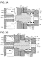
- Figs. 3A and 3B are an explanatory view for explaining an operation of the sub valve 25 and the pressure equalizing path composed of the holes 21a, 22a, 23a, 24a, 3d.
- Fig. 3A shows a condition that the sub valve 25 is separated from the sub valve seat 122, and corresponds to a process that the main valve body 5 is moved to the right side in Fig. 1 , or a process that the main valve body 5 is moved to the left side from the center of the valve housing 1.
- the step end wall 25a of the sub valve 25 abuts on the stopper plate 24, and closes the path between the hole 24a of the stopper plate 24 and the hole 23a of the packing 23 and the hole 21a of the fixed disk 21.
- the pressure equalizing path is in a closed condition.
- Fig. 3B corresponds to a condition shown in Fig. 2 where the sub valve 25 abuts on the sub valve seat 122.
- the small diameter portion 252 of the sub valve 25 closes the exhaust path 12a of the sub valve seat 122, and the stopper plate 24 is separated from the step end wall 25a of the sub valve 25.
- the hole 24a of the stopper plate 24, the hole 23a of the packing 23, the hole 21a of the fixed disk 21, and the hole 3d of the joining member 3 communicate with each other.
- the pressure equalizing path is in an open state.
- the high pressure refrigerant in the main valve chamber 11A flows into the sub valve chamber 12A via the transparent hole 3b ( Fig. 2 ) of the joining member 3, the path 3e, the hole 3d, the hole 21a of the fixed disk 21, the hole 22a of the flat spring 22, the hole 23a of the packing 23, and the hole 24a of the stopper plate 24. Then, because the exhaust path 12a of the sub valve seat 122 is closed, the pressure in the main valve chamber 11A and the pressure in the sub valve chamber 12A are equalized, and the flow of this refrigerant is stopped.
- the pressure in the main valve chamber 11A and the pressure in the sub valve chamber 12A are rapidly equalized via the pressure equalizing path. Therefore, a condition where the refrigerant pressure does not affect the packing 23 rapidly comes.
- the sloped portion 232 of the packing 23 is extended from the outer edge of the disk portion 231 toward the center of the cylinder 11, and the sectional shape of the sloped portion 232 is closer to an inner wall of the valve housing 1. Therefore, the high pressure of the main valve chamber 11A is surely maintained.
- Fig. 6 shows another embodiment of the piston, the same elements in Fig. 2 are identified with the same reference numerals, and duplicated explanation is omitted.
- a disk-shaped stopper plate 27 is fixed to the joining member 3, and a ring-shaped packing 28 sliding on an inner wall of the cylinder 11 is fitted into an outer periphery of the stopper plate 27.
- a large hole 27a corresponding to the large diameter portion 251 of the sub valve 25, and a small hole 27b corresponding to the small diameter portion 252 are formed on the center of the stopper plate 27.
- the sub valve 25 is disposed with a gap in the large hole 27a and the small hole 27b.
- the large hole 27a and the small hole 27b compose the pressure equalizing path.
- the above described embodiment is particularly efficient when the refrigerant (liquid) is the carbon dioxide which is used in high pressure.
- various refrigerant such as HCFC (Hydrochlorofluorocarbon) or HFC (hydrofluorocarbon) may be used.
- HCFC Hydrofluorocarbon
- HFC hydrofluorocarbon
- a ball shaped valve may be used as the sub valve 25.
- a flat spring may be used instead of the coil spring 26.
Landscapes
- Physics & Mathematics (AREA)
- Engineering & Computer Science (AREA)
- Fluid Mechanics (AREA)
- Mechanical Engineering (AREA)
- Thermal Sciences (AREA)
- General Engineering & Computer Science (AREA)
- Fluid-Driven Valves (AREA)
- Multiple-Way Valves (AREA)
Description
- The present invention relates to a flow path switching valve for switching a flow path of a refrigerant used in a refrigeration cycle of an air conditioner or the like.
- Conventionally, in the air conditioner, by switching the flow path of the refrigerant of the refrigeration cycle, air cooling and heating operations are switched. In such a refrigeration cycle, a compressor, two heat exchangers for a condenser and an evaporator, and a flow path switching valve for switching the flow path of the refrigerant disposed in the compressor and two heat exchangers are used.
- For example, such a flow path switching valve is disclosed in
JP, A, 2009-68695 - Further, in the flow path switching valve disclosed in the patent document 1, when the piston main body is moved, a second valve body (ball) disposed at the piston is in contact with the valve seat provided at an end cap of the valve housing, and by blocking an exhaust pipe provided at the valve seat, the pressures of the main valve chamber at a high pressure side and of the sub valve chamber at a low pressure side are equalized to reduce the differential pressure acting on a packing of the piston. In this way, even when a super high pressure refrigerant such as CO2 is used, durability of the piston is maintained.
- [Patent Document 1]
JP, A, 2009-68695 - In the flow path switching valve of the patent document 1, a circular slope portion is provided around a packing of the piston. A sectional shape of the slope portion is gradually closer to an inner wall of the valve housing as the slope portion extends to an end of the valve housing. Then, while the main valve chamber is in a high pressure, and the sub valve chamber is in a low pressure, when the pressures of the main valve chamber and the sub valve chamber are equalized after the second valve body blocks the exhaust pipe, the high pressure refrigerant at the main valve chamber leaks into the sub valve chamber from a space between the slope portion of the packing and the inner wall of the valve housing. Therefore, there is a problem that it is difficult to smoothly equalize the pressure between the main valve chamber and the sub valve chamber. This also applies for the valves shown in
US-2976701 andUS-4966194 . - An object of the present invention is to solve the above-described problem, and to surely equalize the pressure between the main valve chamber and the sub valve chamber after the main valve body is moved, and improve the durability of the piston, in the flow path switching valve receiving two pistons and the main valve body in a joint manner in the tubular valve housing for switching the flow path of the refrigerant passing through a plurality of pipes by sliding the main valve body relative to the valve seat due to the differential pressure of the refrigerant between the main valve chamber inside the piston and the sub valve chamber outside the piston.
- In order to attain the object, according to the present invention, there is provided a flow path switching valve for switching a flow of a refrigerant receiving two pistons joined together in a tubular valve housing disposed on an axial line of the valve housing, said two pistons partitioning the valve housing into a center main valve chamber to which a high pressure pipe is connected and two sub valve chambers at both sides of the main valve chamber,
wherein a main valve seat connected to a low pressure pipe and two switching pipes is disposed in the main valve chamber, and a main valve body slidable in the axial direction relative to the main valve seat is connected to the piston,
wherein by introducing a high pressure refrigerant into any one of the two sub valve chambers, and by reducing a pressure of the other sub valve chamber, the piston and the main valve body are moved to the sub valve chamber side due to a differential pressure between the sub valve chamber of which pressure is reduced and the main valve chamber,
whereby with a concave portion of the valve body, the low pressure pipe alternatively communicates with any one of the two switching pipes, and the other switching pipe communicates with the high pressure pipe via the main valve chamber to switch the flow of the refrigerant,
wherein sub valve seats projected toward the main valve chamber and in which an exhaust path for the refrigerant is opened in the valve housing are formed at both ends of the valve housing,
wherein a pressure equalizing path for communicating the main valve chamber with the sub valve chamber is formed on the axial line corresponding to the sub valve seat, and a sub valve is arranged in the pressure equalizing path for switching open/close of the pressure equalizing path by moving the sub valve in an axial line direction relative to the pressure equalizing path, and
wherein when the piston finishes moving to the sub valve chamber of which pressure is reduced, the sub valve of the piston closes an opening of the sub valve seat at the sub valve chamber side, and the sub valve seat abuts on the sub valve to open the pressure equalizing path, thereby the pressures between the sub valve chamber of which pressure is reduced and the main valve chamber is equalized via the pressure equalizing path. - Preferably, the piston includes a packing contacting an inner wall of the valve housing, and a sloped portion extending circularly at the center of the valve housing is formed on an outer periphery of the packing. Further, a sectional shape of the sloped portion is gradually closer to the inner wall of the valve housing as the sloped portion extends toward the center of the valve housing.
- According to the flow path switching valve of the present invention, when the piston finishes moving to the sub valve chamber of which pressure is reduced, the sub valve of the piston closes the opening of the sub valve seat at the sub valve chamber side. Therefore, the reduction of the pressure in the sub valve chamber is stopped, and the sub valve seat abuts on the sub valve to open the pressure equalizing path, thereby the refrigerant flows from the main valve chamber to the sub valve chamber via the pressure equalizing path. Thus, the differential pressure between the main valve chamber and the sub valve chamber is equalized smoothly. Thus, because a pressure load acting on a sealing member of the piston is eliminated when the piston is not moved, a creep deformation of the sealing member is prevented. Further, a stress deformation of a member composing the piston is prevented. Accordingly, the flow path switching valve of the present invention is particularly suitable for a super high pressure refrigerant such as CO2 refrigerant.
- According to the preferable flow path switching valve of the present invention, in addition to the effect described above, when the pressure of the sub valve chamber is reduced, the high pressure refrigerant at the main valve chamber presses the sloped portion of the packing of the piston positioned between the pressure-reduced sub valve chamber and the high pressure main valve chamber toward the inner wall of the valve housing. Therefore, this packing can surely seal the pressure-reduced sub valve chamber and the main valve chamber, and the piston and the main valve body is surely moved.
- These and other objects, features, and advantages of the present invention will become more apparent upon reading of the following detailed description along with the accompanied drawings.
-
-
Fig. 1 is a schematic view showing a flow path switching valve, a pilot valve, and a refrigeration cycle according to an embodiment of the present invention; -
Fig. 2 is a main part sectional view of the flow path switching valve according to the embodiment; -
Figs. 3A, 3B are a main part operation explanatory view of the flow path switching valve according to the embodiment; -
Fig. 4 is a main part sectional view of the pilot valve according to the embodiment; -
Figs. 5A, 5B are a timing chart showing a driving example of the pilot valve according to the embodiment; and -
Fig. 6 is a main part sectional view showing another example of a piston of the flow path switching valve according to the embodiment. - Next, an embodiment of the present invention will be explained.
Fig. 1 is a schematic view showing a flow path switching valve, a pilot valve, and a refrigeration cycle according to the embodiment. A flowpath switching valve 10 of this embodiment is a four way switching valve. This flowpath switching valve 10 is connected to apilot valve 20 with a pipe. In the flowpath switching valve 10, a valve housing 1 is a tubular shape, and composed of acylindrical cylinder 11 and two disk-shaped caps caps cylinder 11 by welding or the like so as to close ends of thecylinder 11. A center axis of thecylinder 11 and thecaps circular concavities 121 are formed at thecylinder 11 side of thecaps - Two
pistons member 3 are received in the valve housing 1. In this way, an inside of the valve housing 1 composed of an inside of thecylinder 11 andcircular concavities caps pistons main valve chamber 11A and twosub valve chambers main valve chamber 11A. - A
main valve seat 4 is disposed at the center of themain valve chamber 11A, and a main valve body 5 sliding in the axis line L1 direction of the valve housing 1 is disposed on themain valve seat 4.E port 4a,S port 4b, andC port 4c arranged in a straight line in the axis line L1 direction of the valve housing 1 are formed in themain valve seat 4. Ejoint pipe 13a, Sjoint pipe 13b, Cjoint pipe 13c are respectively attached toE port 4a,S port 4b, andC port 4c. Further, D port 11a is formed at a position facing themain valve seat 4 disposed at the center of thecylinder 11. Djoint pipe 13d is attached to D port 11a. Incidentally, Ejoint pipe 13a and Cjoint pipe 13c correspond to a switching pipe, Sjoint pipe 13b corresponds to a low pressure pipe, and Djoint pipe 13d corresponds to a high pressure pipe. In this way, themain valve chamber 11A is connected to Djoint pipe 13d as the high pressure pipe, and themain valve seat 4 is connected to the low pressure pipe and two switching pipes. - A valve body
fitting hole 3a is formed at the center of the joiningmember 3, andtransparent holes fitting hole 3a. The main valve body 5 is fitted into the valve bodyfitting hole 3a, and held with a little play in the axial line L direction relative to the joiningmember 3. When thepistons main valve seat 4 together with the joiningmember 3 and stopped at one of predetermined left or right positions. - The main valve body 5 is made by insert-molding a bowl-shaped
metal plate 51 with a resin-mademember 52. Amain valve concavity 5A is formed on an inside of themetal plate 51. The main valve body 5 communicates theS port 4b and theE port 4a via themain valve concavity 5A at a left end position shown inFig. 1 . At this time, theC port 4c is communicated with the D port 11a mainly via thetransparent hole 3c in themain valve chamber 11A. Further, the main valve body 5 communicates theS port 4b and theC port 4c via themain valve concavity 5A at a right end position inFig. 1 . At this time, theE port 4a is communicated with the D port 11a mainly via thetransparent hole 3b in themain valve chamber 11A. - The S
joint pipe 13b is connected to an inlet of acompressor 30 via alow pressure pipe 14a, and the Djoint pipe 13d is connected to an outlet of thecompressor 30 via ahigh pressure pipe 14b. The Cjoint pipe 13c is connected to anindoor unit 50 via apipe 14c, and the Ejoint pipe 13a is connected to anoutdoor unit 40 via apipe 14d. Theoutdoor unit 40 and theindoor unit 50 are connected to each other with apipe 14e via athrottle unit 60. The refrigeration cycle is formed by a route composed of the Cjoint pipe 13c, theoutdoor unit 40, thethrottle unit 60, theindoor unit 50, and the Ejoint pipe 13a, and by a route composed of the Sjoint pipe 13b, thecompressor 30, and the Djoint pipe 13d. - Then, the
pilot valve 20 switches the position of the main valve body 5 of the flowpath switching valve 10 as described later. The high pressure refrigerant compressed by thecompressor 30 flows from the Djoint pipe 13d via the D port 11a to themain valve chamber 11A, and in a cooling operation ofFig. 1 , the high pressure refrigerant flows from theC port 4c to theoutdoor unit 40. Further, in a heating operation when the main valve body 5 is switched, the high pressure refrigerant flows from theE port 4a to theindoor unit 50. Namely, in the cooling operation, the refrigerant discharged from thecompressor 30 is circulated from the Cjoint pipe 13c via theoutdoor unit 40, thethrottle unit 60, theindoor unit 50, to the Ejoint pipe 13a. Theoutdoor unit 40 works as a condenser, and theindoor unit 50 works as an evaporator to cool the air. Further, in the heating operation, the refrigerant is circulated inversely. Theindoor unit 50 works as the condenser, and theoutdoor unit 40 works as the evaporator to heat the air. - A
sub valve seat 122 projected toward an inside of thecylinder 11 at the center of the circular concavity 121 (on the axial line L1) is formed on each ofcaps exhaust path 12a penetrating from a side of thecap 12 to anend 122a of thesub valve seat 122 is formed on each ofcaps pipes exhaust paths - In
Fig. 1 , thepilot valve 20 includes two electromagnetic actuators. Thispilot valve 20 has a block-shapedvalve housing 61, and twoplunger cases valve housing 61. Further, adsorbers 63, 63 are air-tightly fixed to ends of theplunger cases plunger 65 is disposed in theplunger cases adsorbers plunger cases adsorber 63 becomes a magnetic adsorption surface relative to theplunger 65. - A high pressure
joint pipe 64d, a low pressurejoint pipe 64b, and two switchingjoint pipes valve housing 61. The high pressurejoint pipe 64d is connected to the Djoint pipe 13d of the fourway switching valve 10 by a guidingpipe 14f, and the low pressurejoint pipe 64b is connected to the Sjoint pipe 13b of the fourway switching valve 10 by a guidingpipe 14g. Further, the switchingjoint pipes pipes way switching valve 10. Incidentally, the high pressurejoint pipe 64d, the low pressurejoint pipe 64b, the switchingjoint pipes pipes -
Fig. 4 is a sectional view showing in detail a main part of thepilot valve 20. A cylindricalpilot valve chamber 61A is formed in thevalve housing 61. Theplunger cases pilot valve chamber 61A coaxially with an axial line L2. Theplunger cases pilot valve seat 66 is attached between theplunger cases pilot valve chamber 61A. Apilot valve body 67 sliding in an axial line L2 direction is provided on thepilot valve seat 66. Apilot switching port 61a, a pilotlow pressure port 61b, and apilot switching port 61c are arranged in a line in the axial line L2 direction in thepilot valve seat 66. The switchingjoint pipe 64a, the low pressurejoint pipe 64b, and the switchingjoint pipe 64c are respectively attached to thepilot switching port 61a, the pilotlow pressure port 61b, and thepilot switching port 61c. Further, a pilothigh pressure port 61d is formed at a position opposite to thepilot valve seat 66 in the middle of thevalve housing 61. The high pressurejoint pipe 64d is attached to the pilothigh pressure port 61d. - The
plunger 65 is disposed in theplunger cases pilot valve chamber 61A. Theplunger 65 is in a substantially cylindrical shape, and includes asmall diameter portion 651 at the center side, andlarge diameter portions small diameter portion 651, and aligned with inner walls of theplunger cases plunger 65 includes a D-cutsurface 65a which is partially cut parallel to the axial line L2. This D-cutsurface 65a faces thepilot valve seat 66. A valve body holding hole 65b is drilled from the D-cutsurface 65a in the center of thesmall diameter portion 651. A communicatinghole 65c is formed opposite to the D-cutsurface 65a from the valve body holding hole 65b. Thepilot valve body 67 and acoil spring 68 are disposed in the valve body holding hole 65b. - A
pilot concavity 67a is formed on thepilot valve body 67 at thepilot valve seat 66 side. Thepilot valve body 67 makes thepilot switching port 61a and the pilotlow pressure port 61b communicate with each other via thepilot concavity 67a at a left end position inFig. 4 . At this time, thepilot switching port 61c communicates with the pilothigh pressure port 61d via thepilot valve chamber 61A and a circumference of thesmall diameter portion 651. Further, thepilot valve body 67 makes thepilot switching port 61c and the pilotlow pressure port 61b communicate with each other via thepilot concavity 67a at a right end position inFig. 4 . At this time, thepilot switching port 61a communicates with the pilothigh pressure port 61d via thepilot valve chamber 61A and a circumference of thesmall diameter portion 651. - In this manner, in the
pilot valve 20, by energizing the electromagnet coil 72, theplunger 65 is adsorbed onto theadsorber 63 to move thepilot valve body 67 straight along the axial line L2. Thus, by switching a condition that the high pressure refrigerant is supplied to the left sidesub valve chamber 12A of the fourway switching valve 10 from thepilot switching port 61a, and the pressure of the right sidesub valve chamber 12A is reduced, and a condition that the high pressure refrigerant is supplied to the right sidesub valve chamber 12A of the fourway switching valve 10 from thepilot switching port 61c, and the pressure of the left sidesub valve chamber 12A is reduced, the flow path of the refrigeration cycle is switched. - Incidentally, the
pilot valve body 67 is pressed onto apilot valve seat 66 by thecoil spring 68, thereby a sealing property between thepilot valve body 67 and thepilot valve seat 66 is increased. Further, thepilot valve seat 66 is a metallic member, and thepilot valve body 67 is a resin-made member. Therefore, due to a plastic property of thepilot valve body 67, the sealing property between thepilot valve body 67 and thepilot valve seat 66 is further increased. This high sealing property is effective, in particular, when the super high pressure CO2 is used as the refrigerant. -
Figs. 5A, 5B are a timing chart showing an example of an energizing control to the two electromagnet coils 72, 72. InFig. 1 , the left side electromagnet coil 72 is defined as "coil A", and the right side electromagnet coil 72 is defined as "coil B". As shown inFig. 5A , when the coil A is energized (ON), the coil B is not energized (OFF). Thereby, thepilot valve body 67 is moved to the left side position (the coil A side). Then, the pilothigh pressure port 61d and thepilot switching port 61c communicate with each other, and thepilot switching port 61a and the pilotlow pressure port 61b communicate with each other. Then, even when the coil A is not energized (OFF), the position of thepilot valve body 67 is maintained. Next, while the coil A is not energized, when the coil B is energized (ON), thepilot valve body 67 is moved to the right side position (the coil B side). Then, the pilothigh pressure port 61d and thepilot switching port 61a communicate with each other, and thepilot switching port 61c and the pilotlow pressure port 61b communicate with each other. Then, even when the coil B is not energized (OFF), the position of thepilot valve body 67 is maintained. Incidentally, as shown inFig. 5B , after the electromagnet coil 72 is energized to switch the position of thepilot valve body 67, a holding voltage may be applied to the electromagnet coil 72 until the next switching is occurred. - According to the
pilot valve 20 of this embodiment, theplunger 65 holding thepilot valve body 67 is disposed in the twoplunger cases valve housing 61. Thepilot valve body 67 is slidable on thepilot valve seat 66 connected to a plurality of joint pipes together with theplunger 65 in the axial line L2 direction. Theadsorbers plunger cases adsorbers plunger cases plunger 65 is adsorbed onto theadsorber 63, thereby the flow paths of the refrigerant in the pipes are switched with thepilot valve body 67. - The
pilot valve 20 of this embodiment is superior to, for example, a pilot valve disclosed inJP, A, H08-170865 - On the contrary, according to the
pilot valve 20 of this embodiment, the spring is not used, and two facing electromagnet actuators are provided. By switching the two electromagnet actuators reciprocally, the pilot valve body on which high differential pressure acts can be moved without an efficiency reduction due to the spring force, and with small-sized low-cost electromagnetic actuators. Further, when the differential pressure is generated on the pilot valve body, because when the coil is not energized (OFF), the position of the pilot valve body is maintained, a latching mechanism is realized to improve the energy-saving property. Further, according to the conventional pilot valve, when the adsorption force is reduced with a low voltage, a magnetic noise is generated due to a balance between the electromagnetic force and the spring force. However, according to thepilot valve 20 of this embodiment, because the spring is not used, the magnetic noise is reduced. - In this manner, the high pressure refrigerant flowing into the
pilot valve 20 from the high pressurejoint pipe 64d flows out from the switchingjoint pipe sub valve chamber 12A in the fourway switching valve 10. At this time, the right or left sidesub valve chamber 12A of the flowpath switching valve 10 communicates with the low pressure side via the low pressurejoint pipe 64b. In this manner, owing to thepilot valve 20, in the fourway switching valve 10, one sub valve chamber is in high pressure, and the other sub valve chamber is in low pressure. Incidentally, the high pressure refrigerant is always supplied to themain valve chamber 11A. Therefore, the differential pressure between the low pressure at thesub valve chamber 12A and the high pressure at themain valve chamber 11A acts on thepiston 2 at the low pressure sub valve chamber side, and mainly due to this differential pressure, thepiston 2 and the main valve body 5 is moved to the low pressuresub valve chamber 12A side to switch the position of the main valve body 5. - Here, in
Fig. 1 ,pistons right side piston 2 will be explained with reference toFig. 2 . Thepiston 2 includes a fixeddisk 21 fixed to the joiningmember 3, aflat spring 22, a packing 23, acircular stopper plate 24, asub valve 25, and acoil spring 26. They are coaxially disposed relative to the axial line L1. - The
flat spring 22 is made of an elastically deformable thin metal plate, and integrally includes acircular disk portion 221 and asloped biasing portion 222. An outer diameter of thedisk portion 221 is substantially the same as the fixeddisk 21. The slopedbiasing portion 222 is formed in a ring shape, and disposed on a whole outer edge of thedisk portion 221. The slopedbiasing portion 222 is extended from the outer edge of thedisk portion 221 toward the center of the cylinder 11 (valve housing 1). Namely, as thesloped biasing portion 222 is extended toward the center of the valve housing 1, a sectional shape of the sloped biasingportion 222 is closer to an inner wall of the valve housing 1. The slopedbiasing portion 222 is sloped relative to both the axial line L1 direction and a radial direction. - The packing 23 is made of synthetic resin, and integrally includes a
circular disk portion 231 and asloped portion 232. An outer diameter of thedisk portion 231 is substantially the same as the fixeddisk 21. The slopedportion 232 is formed in a ring shape, and disposed on a whole outer edge of thedisk portion 231. The slopedportion 232 is extended from the outer edge of thedisk portion 231 toward the center of the cylinder 11 (valve housing 1). Namely, as the slopedportion 232 is extended toward the center of the valve housing 1, a sectional shape of the slopedportion 232 is closer to an inner wall of the valve housing 1. The slopedbiasing portion 232 is sloped relative to both the axial line L1 direction and the radial direction. - Thus, the
flat spring 22 and the packing 23 are formed in the substantially same shape, and theflat spring 22 is disposed inside of the packing 23. By holding thedisk portion 221 and thedisk portion 231 between the fixeddisk 21 and thestopper plate 24, theflat spring 22 and the packing 23 are fixed. The elastically deformableflat spring 22 is slid on the inner wall of the valve housing 1 at an end of the sloped biasingportion 222 away from thedisk portion 221 via the slopedportion 232 of the packing 23. Further, an elastically restoring force is generated by theflat spring 22 for biasing the slopedportion 232 of the packing 23 away from the inner wall of the valve housing 1 toward the inner wall of the valve housing 1. Further, in a state that theflat spring 22 is assembled in the valve housing 1 (cylinder 11), the end of the sloped biasingportion 222 away from thedisk portion 221 pushes the slopedportion 232 of the packing 23 toward the inner wall of the valve housing 1. Thereby, the packing 23 surely seals thepiston 2 on an inner circumference of thecylinder 11 with regard to the high pressure refrigerant in themain valve chamber 11A. - In the each
piston 2,circular holes disk 21, theflat spring 22, the packing 23, and thestopper plate 24. Further, acircular hole 3d is formed at the fixeddisk 21 side of the joiningmember 3, and thecircular hole 3d of the joiningmember 3 communicates with thetransparent hole 3b (transparent hole 3c at the right side) via apath 3e. Among them, diameters of thehole 3d of the joiningmember 3, thehole 21a of the fixeddisk 21, thehole 22a of theflat spring 22, and thehole 23a of the packing 23 are substantially the same, and a diameter of thehole 24a of thestopper plate 24 is smaller than them. A pressure equalizing path is composed of theseholes sub valve 25 is disposed with a gap on outer peripheries of theholes - The
sub valve 25 is composed of a cylindricallarge diameter portion 251, a cylindricalsmall diameter portion 252, and acylindrical boss portion 253. Thelarge diameter portion 251 is inserted into theholes small diameter portion 252 is inserted into thehole 24a. Further, thecoil spring 26 is fitted into theboss portion 253 in thehole 3d of the joiningmember 3. Thesub valve 25 is pushed toward thecap 12 by thecoil spring 26. Astep end wall 25a is formed between thelarge diameter portion 251 and thesmall diameter portion 252. - An operation of the
sub valve 25 is described below. When the low pressure is introduced into onesub valve chamber 12A, and the differential pressure is generated between themain valve chamber 11A and the one sub valve chamber, thewhole piston 2 including thesub valve 25 is moved toward the low pressure sub valve chamber (cap 12). Then, when thestopper plate 24 abuts on thecap 12, thepiston 2 is stopped. In a process of movement of thepiston 2, firstly, an end (small diameter portion 252) of thesub valve 25 contacts thesub valve seat 122. At this time, theexhaust path 12a disposed on thesub valve chamber 12A is closed. Even after the end of thesub valve 25 contacts thesub valve seat 122, thepiston 2 is still moved because the differential pressure between themain valve chamber 11A and thesub valve chamber 12A overcomes the biasing force of thecoil spring 26. Thepiston 2 keeps on moving until thestopper plate 24 abuts on thecap 12. In this moving interval, a gap is always generated between thestep end wall 25a of thesub valve 25 and thestopper plate 24. Therefore, the refrigerant flows from themain valve chamber 11A to thesub valve chamber 12A via the gap to equalize the pressure. When the pressure in themain valve chamber 11A and the pressure in the 12A are equalized, thepiston 2 is stopped at a position where the biasing force of thecoil spring 26 and a frictional force between thepiston 2 and the inner periphery of thecylinder 11 stay in balance. Incidentally, when the pressure of the oppositesub valve chamber 12A is reduced from this condition, and thepiston 2 is removed from thecap 12, due to the biasing force of thecoil spring 26, while thesub valve 25 still contacts thesub valve seat 122, thestopper plate 24 abuts on thestep end wall 25a. Then, thepiston 2 including thesub valve 25 is moved. -
Figs. 3A and 3B are an explanatory view for explaining an operation of thesub valve 25 and the pressure equalizing path composed of theholes Fig. 3A shows a condition that thesub valve 25 is separated from thesub valve seat 122, and corresponds to a process that the main valve body 5 is moved to the right side inFig. 1 , or a process that the main valve body 5 is moved to the left side from the center of the valve housing 1. At this time, thestep end wall 25a of thesub valve 25 abuts on thestopper plate 24, and closes the path between thehole 24a of thestopper plate 24 and thehole 23a of the packing 23 and thehole 21a of the fixeddisk 21. Namely, the pressure equalizing path is in a closed condition. -
Fig. 3B corresponds to a condition shown inFig. 2 where thesub valve 25 abuts on thesub valve seat 122. At this time, thesmall diameter portion 252 of thesub valve 25 closes theexhaust path 12a of thesub valve seat 122, and thestopper plate 24 is separated from thestep end wall 25a of thesub valve 25. Thereby, thehole 24a of thestopper plate 24, thehole 23a of the packing 23, thehole 21a of the fixeddisk 21, and thehole 3d of the joiningmember 3 communicate with each other. Namely, the pressure equalizing path is in an open state. Thereby, as shown by a dotted arrow inFig. 3B , the high pressure refrigerant in themain valve chamber 11A flows into thesub valve chamber 12A via thetransparent hole 3b (Fig. 2 ) of the joiningmember 3, thepath 3e, thehole 3d, thehole 21a of the fixeddisk 21, thehole 22a of theflat spring 22, thehole 23a of the packing 23, and thehole 24a of thestopper plate 24. Then, because theexhaust path 12a of thesub valve seat 122 is closed, the pressure in themain valve chamber 11A and the pressure in thesub valve chamber 12A are equalized, and the flow of this refrigerant is stopped. - In this manner, the pressure in the
main valve chamber 11A and the pressure in thesub valve chamber 12A are rapidly equalized via the pressure equalizing path. Therefore, a condition where the refrigerant pressure does not affect the packing 23 rapidly comes. According to this embodiment, as the slopedportion 232 of the packing 23 is extended from the outer edge of thedisk portion 231 toward the center of thecylinder 11, and the sectional shape of the slopedportion 232 is closer to an inner wall of the valve housing 1. Therefore, the high pressure of themain valve chamber 11A is surely maintained. -
Fig. 6 shows another embodiment of the piston, the same elements inFig. 2 are identified with the same reference numerals, and duplicated explanation is omitted. In this piston 2', a disk-shapedstopper plate 27 is fixed to the joiningmember 3, and a ring-shapedpacking 28 sliding on an inner wall of thecylinder 11 is fitted into an outer periphery of thestopper plate 27. Further, alarge hole 27a corresponding to thelarge diameter portion 251 of thesub valve 25, and asmall hole 27b corresponding to thesmall diameter portion 252 are formed on the center of thestopper plate 27. Thesub valve 25 is disposed with a gap in thelarge hole 27a and thesmall hole 27b. Thelarge hole 27a and thesmall hole 27b compose the pressure equalizing path. When thesub valve 25 abuts on thesub valve seat 122, and thestopper plate 27 is moved to abut on thecap 12, during this movement, an end wall between thelarge hole 27a and thesmall hole 27b is separated from thestep end wall 25a of thesub valve 25 to open the pressure equalizing path. Further, from this condition, when thestopper plate 27 is removed from thecap 12, thestopper plate 27 abuts on thestep end wall 25a to close the pressure equalizing path. These operations of thesub valve 25 and the pressure equalizing path are the same as the above described embodiment. - The above described embodiment is particularly efficient when the refrigerant (liquid) is the carbon dioxide which is used in high pressure. However, various refrigerant such as HCFC (Hydrochlorofluorocarbon) or HFC (hydrofluorocarbon) may be used. Further, according to the present invention, a ball shaped valve may be used as the
sub valve 25. Further, a flat spring may be used instead of thecoil spring 26. - Although the present invention has been fully described by way of example with reference to the accompanying drawings, it is to be understood that various changes and modifications will be apparent to those skilled in the art. Therefore, unless otherwise such changes and modifications depart from the scope of the present invention hereinafter defined, they should be construed as being included therein.
Claims (2)
- A flow path switching valve (10) for switching a flow of a refrigerant receiving two pistons (2, 2) joined together in a tubular valve housing (1) disposed on an axial line of the valve housing, said two pistons (2) partitioning the valve housing (1) into a center main valve chamber (11a) to which a high pressure pipe is connected and two sub valve chambers (12A, 12A) at both sides of the main valve chamber,
wherein a main valve seat (4) connected to a low pressure pipe and two switching pipes is disposed in the main valve chamber (1), and a main valve body (5) slidable in the axial direction relative to the main valve seat (4) is connected to the piston (2),
wherein by introducing a high pressure refrigerant into any one of the two sub valve chambers (12A), and by reducing a pressure of the other sub valve chamber, the piston (2) and the main valve body (5) are moved to the sub valve chamber (12A) side due to a differential pressure between the sub valve chamber (12A) of which pressure is reduced and the main valve chamber (11A),
whereby with a concave portion (5A) of the valve body (5), the low pressure pipe alternatively communicates with any one of the two switching pipes, and the other switching pipe communicates with the high pressure pipe via the main valve chamber (11A) to switch the flow of the refrigerant,
characterized in that
sub valve seats (122) projected toward the main valve chamber (11A) and in which an exhaust path for the refrigerant is opened in the valve housing (1) are formed at both ends of the valve housing,
a pressure equalizing path for communicating the main valve chamber (11A) with the sub valve chamber (12A) is formed on the axial line corresponding to the sub valve seat (122), and a sub valve (25) arranged in the pressure equalizing path for switching open/close of the pressure equalizing path by moving the sub valve (25) in an axial line direction relative to the pressure equalizing path, and
when the piston finishes moving to the sub valve chamber (12A) of which pressure is reduced, the sub valve (25) of the piston (2) closes an opening of the sub valve seat (122) at the sub valve chamber side, and the sub valve seat (122) abuts on the sub valve (25) to open the pressure equalizing path, thereby the pressures between the sub valve chamber (12A) of which pressure is reduced and the main valve chamber (11A) is equalized via the pressure equalizing path. - The flow path switching valve as claimed in claim 1,
wherein the piston (2) includes a packing (23) contacting an inner wall of the valve housing, and a sloped portion (122) extending circularly at the center of the valve housing is formed on an outer periphery of the packing, and
wherein a sectional shape of the sloped portion (222) is gradually closer to the inner wall of the valve housing as the sloped portion extends toward the center of the valve housing (1).
Applications Claiming Priority (1)
| Application Number | Priority Date | Filing Date | Title |
|---|---|---|---|
| JP2010112976A JP5080612B2 (en) | 2010-05-17 | 2010-05-17 | Flow path switching valve |
Publications (3)
| Publication Number | Publication Date |
|---|---|
| EP2388541A2 EP2388541A2 (en) | 2011-11-23 |
| EP2388541A3 EP2388541A3 (en) | 2015-04-29 |
| EP2388541B1 true EP2388541B1 (en) | 2016-07-06 |
Family
ID=44509826
Family Applications (1)
| Application Number | Title | Priority Date | Filing Date |
|---|---|---|---|
| EP11154126.4A Active EP2388541B1 (en) | 2010-05-17 | 2011-02-11 | Flow path switching valve |
Country Status (3)
| Country | Link |
|---|---|
| EP (1) | EP2388541B1 (en) |
| JP (1) | JP5080612B2 (en) |
| CN (1) | CN102252114B (en) |
Families Citing this family (19)
| Publication number | Priority date | Publication date | Assignee | Title |
|---|---|---|---|---|
| JP6215802B2 (en) * | 2014-09-10 | 2017-10-18 | 株式会社鷺宮製作所 | Slide valve and refrigeration cycle |
| JP6478585B2 (en) * | 2014-11-26 | 2019-03-06 | 株式会社不二工機 | Flow path switching valve |
| JP6478586B2 (en) * | 2014-11-26 | 2019-03-06 | 株式会社不二工機 | Flow path switching valve |
| JP6461589B2 (en) * | 2014-12-12 | 2019-01-30 | 株式会社不二工機 | Flow path switching valve |
| JP6378114B2 (en) * | 2015-03-06 | 2018-08-22 | 株式会社鷺宮製作所 | Slide valve and refrigeration cycle |
| CN106286891B (en) * | 2015-05-15 | 2019-06-11 | 浙江盾安人工环境股份有限公司 | Combined electromagnetic switching valve and its air conditioning system |
| JP2017155887A (en) * | 2016-03-03 | 2017-09-07 | 株式会社鷺宮製作所 | Sliding switching valve and refrigeration cycle system |
| JP7137834B2 (en) * | 2018-09-18 | 2022-09-15 | 株式会社不二工機 | four-way switching valve |
| WO2020110841A1 (en) * | 2018-11-29 | 2020-06-04 | 株式会社不二工機 | Flow path switching valve |
| JP7175499B2 (en) * | 2018-12-25 | 2022-11-21 | 株式会社不二工機 | Flow switching valve |
| CN110410533B (en) * | 2019-08-30 | 2024-09-17 | 邵阳学院 | Four-way valve for air conditioner |
| CN111229551B (en) * | 2020-04-01 | 2024-09-10 | 常州纳捷机电科技有限公司 | Novel duplex site gluing machine |
| CN113531152B (en) * | 2020-04-17 | 2025-06-24 | 浙江三花智能控制股份有限公司 | Solenoid switching valve and refrigeration system having the same |
| CN112503211B (en) * | 2020-12-15 | 2024-12-06 | 珠海格力电器股份有限公司 | Control valve core, control valve, outdoor unit and air conditioner |
| JP2022124369A (en) * | 2021-02-15 | 2022-08-25 | イーグル工業株式会社 | Switching valve device |
| JP7280631B2 (en) * | 2021-06-08 | 2023-05-24 | 株式会社不二工機 | Flow switching valve |
| CN114811103A (en) * | 2022-04-22 | 2022-07-29 | 浙江三花智能控制股份有限公司 | Electromagnetic directional valve and main valve thereof |
| JP7649277B2 (en) * | 2022-07-08 | 2025-03-19 | 株式会社鷺宮製作所 | Slide type switching valve and refrigeration cycle system using the same |
| JP2025075535A (en) * | 2023-10-31 | 2025-05-15 | 株式会社鷺宮製作所 | Slide type switching valve and refrigeration cycle system |
Family Cites Families (15)
| Publication number | Priority date | Publication date | Assignee | Title |
|---|---|---|---|---|
| US2976701A (en) * | 1957-12-30 | 1961-03-28 | Ranco Inc | Reversing valve for refrigerating systems |
| US3400736A (en) * | 1966-05-31 | 1968-09-10 | Controls Co Of America | Reversing valve |
| JPS58119604U (en) * | 1982-02-10 | 1983-08-15 | 極東開発工業株式会社 | dump cylinder |
| JPS5958277A (en) * | 1982-09-28 | 1984-04-03 | Matsushita Electric Ind Co Ltd | solenoid three way valve |
| US4966194A (en) * | 1988-07-13 | 1990-10-30 | Ranco Japan Ltd. | Four-way switching valve device |
| US4926897A (en) * | 1989-06-12 | 1990-05-22 | C. H. Perrott, Inc. | Automatic fluid pressure equalizing valve |
| CN1081499A (en) * | 1992-07-23 | 1994-02-02 | 吴满庆 | Five-way electromagnetic valve |
| LU88277A1 (en) * | 1993-05-27 | 1994-12-01 | Hydrolux Sarl | Pilot operated servo valve |
| JP2925941B2 (en) * | 1994-08-26 | 1999-07-28 | 新明和工業株式会社 | Fluid cylinder |
| JPH08170865A (en) | 1994-12-19 | 1996-07-02 | Sanyo Electric Co Ltd | Switching valve for heat pump air conditioner |
| JP2002155908A (en) * | 2000-11-22 | 2002-05-31 | Oil Drive Kogyo Kk | Hydraulic cylinder |
| JP4818668B2 (en) * | 2005-09-15 | 2011-11-16 | 株式会社鷺宮製作所 | Flow path switching valve |
| JP2009068695A (en) * | 2007-08-20 | 2009-04-02 | Saginomiya Seisakusho Inc | Switching valve and reversible cycle refrigeration system |
| CN101245864B (en) * | 2008-03-17 | 2010-09-22 | 时代嘉华(中国)科技有限公司 | Self-operated three-way valve used for coolant circulating type machine room special machine |
| JP2010112976A (en) | 2008-11-04 | 2010-05-20 | Nikon Corp | Lens drive device, lens position detecting device, and imaging apparatus using them |
-
2010
- 2010-05-17 JP JP2010112976A patent/JP5080612B2/en active Active
-
2011
- 2011-02-11 EP EP11154126.4A patent/EP2388541B1/en active Active
- 2011-04-25 CN CN2011101091837A patent/CN102252114B/en active Active
Also Published As
| Publication number | Publication date |
|---|---|
| JP5080612B2 (en) | 2012-11-21 |
| EP2388541A3 (en) | 2015-04-29 |
| JP2011241870A (en) | 2011-12-01 |
| CN102252114B (en) | 2013-02-13 |
| CN102252114A (en) | 2011-11-23 |
| EP2388541A2 (en) | 2011-11-23 |
Similar Documents
| Publication | Publication Date | Title |
|---|---|---|
| EP2388541A2 (en) | Flow path switching valve | |
| US6783110B2 (en) | Proportional solenoid valve | |
| US8157183B2 (en) | Expansion valve, heat pump type refrigeration cycle apparatus, and air handling unit | |
| JP6281046B2 (en) | Control valve for variable capacity compressor | |
| CN111465767B (en) | Capacity control valve and control method for capacity control valve | |
| CN106545670B (en) | Direct-acting solenoid valve and four-way selector valve provided with same as pilot valve | |
| JP5687026B2 (en) | Three-way valve and vehicle air conditioner using the three-way valve | |
| US20150096630A1 (en) | Electromagnetic valve | |
| CN109990113B (en) | Electromagnetic switching valve and piston | |
| JP3727464B2 (en) | Four-way selector valve | |
| JP2000046213A (en) | Flow path switching valve | |
| JP2000356273A (en) | Four-way selector valve | |
| JP4848548B2 (en) | Expansion valve with solenoid valve | |
| JP4818668B2 (en) | Flow path switching valve | |
| EP1336788B1 (en) | Four-way switching valve | |
| CN113028120A (en) | Electromagnetic switching valve | |
| CN109990115B (en) | Electromagnetic switching valve | |
| JP7367972B2 (en) | pilot valve | |
| JP2013224638A (en) | Control valve | |
| JP6040372B2 (en) | Control valve for variable capacity compressor | |
| JP6040343B2 (en) | solenoid valve | |
| JPH0718494B2 (en) | Four-way valve for refrigeration cycle | |
| JP7738674B2 (en) | Reversible solenoid valve and air conditioning unit having same | |
| JP7847376B2 (en) | Expansion valve | |
| JP2532497B2 (en) | Four-way valve for refrigeration cycle |
Legal Events
| Date | Code | Title | Description |
|---|---|---|---|
| AK | Designated contracting states |
Kind code of ref document: A2 Designated state(s): AL AT BE BG CH CY CZ DE DK EE ES FI FR GB GR HR HU IE IS IT LI LT LU LV MC MK MT NL NO PL PT RO RS SE SI SK SM TR |
|
| AX | Request for extension of the european patent |
Extension state: BA ME |
|
| PUAI | Public reference made under article 153(3) epc to a published international application that has entered the european phase |
Free format text: ORIGINAL CODE: 0009012 |
|
| PUAL | Search report despatched |
Free format text: ORIGINAL CODE: 0009013 |
|
| AK | Designated contracting states |
Kind code of ref document: A3 Designated state(s): AL AT BE BG CH CY CZ DE DK EE ES FI FR GB GR HR HU IE IS IT LI LT LU LV MC MK MT NL NO PL PT RO RS SE SI SK SM TR |
|
| AX | Request for extension of the european patent |
Extension state: BA ME |
|
| RIC1 | Information provided on ipc code assigned before grant |
Ipc: F16K 11/056 20060101ALI20150326BHEP Ipc: F25B 41/04 20060101AFI20150326BHEP |
|
| 17P | Request for examination filed |
Effective date: 20150723 |
|
| RBV | Designated contracting states (corrected) |
Designated state(s): AL AT BE BG CH CY CZ DE DK EE ES FI FR GB GR HR HU IE IS IT LI LT LU LV MC MK MT NL NO PL PT RO RS SE SI SK SM TR |
|
| RIC1 | Information provided on ipc code assigned before grant |
Ipc: F25B 41/04 20060101AFI20151217BHEP Ipc: F16K 11/056 20060101ALI20151217BHEP |
|
| GRAP | Despatch of communication of intention to grant a patent |
Free format text: ORIGINAL CODE: EPIDOSNIGR1 |
|
| INTG | Intention to grant announced |
Effective date: 20160127 |
|
| GRAS | Grant fee paid |
Free format text: ORIGINAL CODE: EPIDOSNIGR3 |
|
| GRAA | (expected) grant |
Free format text: ORIGINAL CODE: 0009210 |
|
| AK | Designated contracting states |
Kind code of ref document: B1 Designated state(s): AL AT BE BG CH CY CZ DE DK EE ES FI FR GB GR HR HU IE IS IT LI LT LU LV MC MK MT NL NO PL PT RO RS SE SI SK SM TR |
|
| REG | Reference to a national code |
Ref country code: GB Ref legal event code: FG4D |
|
| REG | Reference to a national code |
Ref country code: AT Ref legal event code: REF Ref document number: 811005 Country of ref document: AT Kind code of ref document: T Effective date: 20160715 Ref country code: CH Ref legal event code: EP |
|
| REG | Reference to a national code |
Ref country code: IE Ref legal event code: FG4D |
|
| REG | Reference to a national code |
Ref country code: DE Ref legal event code: R096 Ref document number: 602011027873 Country of ref document: DE |
|
| REG | Reference to a national code |
Ref country code: NL Ref legal event code: MP Effective date: 20160706 |
|
| REG | Reference to a national code |
Ref country code: LT Ref legal event code: MG4D |
|
| REG | Reference to a national code |
Ref country code: AT Ref legal event code: MK05 Ref document number: 811005 Country of ref document: AT Kind code of ref document: T Effective date: 20160706 |
|
| PG25 | Lapsed in a contracting state [announced via postgrant information from national office to epo] |
Ref country code: NO Free format text: LAPSE BECAUSE OF FAILURE TO SUBMIT A TRANSLATION OF THE DESCRIPTION OR TO PAY THE FEE WITHIN THE PRESCRIBED TIME-LIMIT Effective date: 20161006 Ref country code: FI Free format text: LAPSE BECAUSE OF FAILURE TO SUBMIT A TRANSLATION OF THE DESCRIPTION OR TO PAY THE FEE WITHIN THE PRESCRIBED TIME-LIMIT Effective date: 20160706 Ref country code: HR Free format text: LAPSE BECAUSE OF FAILURE TO SUBMIT A TRANSLATION OF THE DESCRIPTION OR TO PAY THE FEE WITHIN THE PRESCRIBED TIME-LIMIT Effective date: 20160706 Ref country code: LT Free format text: LAPSE BECAUSE OF FAILURE TO SUBMIT A TRANSLATION OF THE DESCRIPTION OR TO PAY THE FEE WITHIN THE PRESCRIBED TIME-LIMIT Effective date: 20160706 Ref country code: RS Free format text: LAPSE BECAUSE OF FAILURE TO SUBMIT A TRANSLATION OF THE DESCRIPTION OR TO PAY THE FEE WITHIN THE PRESCRIBED TIME-LIMIT Effective date: 20160706 Ref country code: NL Free format text: LAPSE BECAUSE OF FAILURE TO SUBMIT A TRANSLATION OF THE DESCRIPTION OR TO PAY THE FEE WITHIN THE PRESCRIBED TIME-LIMIT Effective date: 20160706 Ref country code: IT Free format text: LAPSE BECAUSE OF FAILURE TO SUBMIT A TRANSLATION OF THE DESCRIPTION OR TO PAY THE FEE WITHIN THE PRESCRIBED TIME-LIMIT Effective date: 20160706 Ref country code: IS Free format text: LAPSE BECAUSE OF FAILURE TO SUBMIT A TRANSLATION OF THE DESCRIPTION OR TO PAY THE FEE WITHIN THE PRESCRIBED TIME-LIMIT Effective date: 20161106 |
|
| REG | Reference to a national code |
Ref country code: FR Ref legal event code: PLFP Year of fee payment: 7 |
|
| PG25 | Lapsed in a contracting state [announced via postgrant information from national office to epo] |
Ref country code: LV Free format text: LAPSE BECAUSE OF FAILURE TO SUBMIT A TRANSLATION OF THE DESCRIPTION OR TO PAY THE FEE WITHIN THE PRESCRIBED TIME-LIMIT Effective date: 20160706 Ref country code: AT Free format text: LAPSE BECAUSE OF FAILURE TO SUBMIT A TRANSLATION OF THE DESCRIPTION OR TO PAY THE FEE WITHIN THE PRESCRIBED TIME-LIMIT Effective date: 20160706 Ref country code: PL Free format text: LAPSE BECAUSE OF FAILURE TO SUBMIT A TRANSLATION OF THE DESCRIPTION OR TO PAY THE FEE WITHIN THE PRESCRIBED TIME-LIMIT Effective date: 20160706 Ref country code: SE Free format text: LAPSE BECAUSE OF FAILURE TO SUBMIT A TRANSLATION OF THE DESCRIPTION OR TO PAY THE FEE WITHIN THE PRESCRIBED TIME-LIMIT Effective date: 20160706 Ref country code: ES Free format text: LAPSE BECAUSE OF FAILURE TO SUBMIT A TRANSLATION OF THE DESCRIPTION OR TO PAY THE FEE WITHIN THE PRESCRIBED TIME-LIMIT Effective date: 20160706 Ref country code: PT Free format text: LAPSE BECAUSE OF FAILURE TO SUBMIT A TRANSLATION OF THE DESCRIPTION OR TO PAY THE FEE WITHIN THE PRESCRIBED TIME-LIMIT Effective date: 20161107 Ref country code: GR Free format text: LAPSE BECAUSE OF FAILURE TO SUBMIT A TRANSLATION OF THE DESCRIPTION OR TO PAY THE FEE WITHIN THE PRESCRIBED TIME-LIMIT Effective date: 20161007 |
|
| REG | Reference to a national code |
Ref country code: DE Ref legal event code: R097 Ref document number: 602011027873 Country of ref document: DE |
|
| PG25 | Lapsed in a contracting state [announced via postgrant information from national office to epo] |
Ref country code: EE Free format text: LAPSE BECAUSE OF FAILURE TO SUBMIT A TRANSLATION OF THE DESCRIPTION OR TO PAY THE FEE WITHIN THE PRESCRIBED TIME-LIMIT Effective date: 20160706 Ref country code: RO Free format text: LAPSE BECAUSE OF FAILURE TO SUBMIT A TRANSLATION OF THE DESCRIPTION OR TO PAY THE FEE WITHIN THE PRESCRIBED TIME-LIMIT Effective date: 20160706 |
|
| PLBE | No opposition filed within time limit |
Free format text: ORIGINAL CODE: 0009261 |
|
| STAA | Information on the status of an ep patent application or granted ep patent |
Free format text: STATUS: NO OPPOSITION FILED WITHIN TIME LIMIT |
|
| PG25 | Lapsed in a contracting state [announced via postgrant information from national office to epo] |
Ref country code: CZ Free format text: LAPSE BECAUSE OF FAILURE TO SUBMIT A TRANSLATION OF THE DESCRIPTION OR TO PAY THE FEE WITHIN THE PRESCRIBED TIME-LIMIT Effective date: 20160706 Ref country code: DK Free format text: LAPSE BECAUSE OF FAILURE TO SUBMIT A TRANSLATION OF THE DESCRIPTION OR TO PAY THE FEE WITHIN THE PRESCRIBED TIME-LIMIT Effective date: 20160706 Ref country code: BG Free format text: LAPSE BECAUSE OF FAILURE TO SUBMIT A TRANSLATION OF THE DESCRIPTION OR TO PAY THE FEE WITHIN THE PRESCRIBED TIME-LIMIT Effective date: 20161006 Ref country code: SM Free format text: LAPSE BECAUSE OF FAILURE TO SUBMIT A TRANSLATION OF THE DESCRIPTION OR TO PAY THE FEE WITHIN THE PRESCRIBED TIME-LIMIT Effective date: 20160706 Ref country code: SK Free format text: LAPSE BECAUSE OF FAILURE TO SUBMIT A TRANSLATION OF THE DESCRIPTION OR TO PAY THE FEE WITHIN THE PRESCRIBED TIME-LIMIT Effective date: 20160706 |
|
| 26N | No opposition filed |
Effective date: 20170407 |
|
| PG25 | Lapsed in a contracting state [announced via postgrant information from national office to epo] |
Ref country code: SI Free format text: LAPSE BECAUSE OF FAILURE TO SUBMIT A TRANSLATION OF THE DESCRIPTION OR TO PAY THE FEE WITHIN THE PRESCRIBED TIME-LIMIT Effective date: 20160706 |
|
| PG25 | Lapsed in a contracting state [announced via postgrant information from national office to epo] |
Ref country code: MC Free format text: LAPSE BECAUSE OF FAILURE TO SUBMIT A TRANSLATION OF THE DESCRIPTION OR TO PAY THE FEE WITHIN THE PRESCRIBED TIME-LIMIT Effective date: 20160706 |
|
| REG | Reference to a national code |
Ref country code: CH Ref legal event code: PL |
|
| GBPC | Gb: european patent ceased through non-payment of renewal fee |
Effective date: 20170211 |
|
| PG25 | Lapsed in a contracting state [announced via postgrant information from national office to epo] |
Ref country code: LI Free format text: LAPSE BECAUSE OF NON-PAYMENT OF DUE FEES Effective date: 20170228 Ref country code: CH Free format text: LAPSE BECAUSE OF NON-PAYMENT OF DUE FEES Effective date: 20170228 |
|
| REG | Reference to a national code |
Ref country code: IE Ref legal event code: MM4A |
|
| PG25 | Lapsed in a contracting state [announced via postgrant information from national office to epo] |
Ref country code: LU Free format text: LAPSE BECAUSE OF NON-PAYMENT OF DUE FEES Effective date: 20170211 |
|
| REG | Reference to a national code |
Ref country code: FR Ref legal event code: PLFP Year of fee payment: 8 |
|
| PG25 | Lapsed in a contracting state [announced via postgrant information from national office to epo] |
Ref country code: IE Free format text: LAPSE BECAUSE OF NON-PAYMENT OF DUE FEES Effective date: 20170211 Ref country code: GB Free format text: LAPSE BECAUSE OF NON-PAYMENT OF DUE FEES Effective date: 20170211 |
|
| PG25 | Lapsed in a contracting state [announced via postgrant information from national office to epo] |
Ref country code: MT Free format text: LAPSE BECAUSE OF NON-PAYMENT OF DUE FEES Effective date: 20170211 |
|
| PG25 | Lapsed in a contracting state [announced via postgrant information from national office to epo] |
Ref country code: AL Free format text: LAPSE BECAUSE OF FAILURE TO SUBMIT A TRANSLATION OF THE DESCRIPTION OR TO PAY THE FEE WITHIN THE PRESCRIBED TIME-LIMIT Effective date: 20160706 |
|
| PG25 | Lapsed in a contracting state [announced via postgrant information from national office to epo] |
Ref country code: HU Free format text: LAPSE BECAUSE OF FAILURE TO SUBMIT A TRANSLATION OF THE DESCRIPTION OR TO PAY THE FEE WITHIN THE PRESCRIBED TIME-LIMIT; INVALID AB INITIO Effective date: 20110211 |
|
| PG25 | Lapsed in a contracting state [announced via postgrant information from national office to epo] |
Ref country code: CY Free format text: LAPSE BECAUSE OF NON-PAYMENT OF DUE FEES Effective date: 20160706 |
|
| PG25 | Lapsed in a contracting state [announced via postgrant information from national office to epo] |
Ref country code: MK Free format text: LAPSE BECAUSE OF FAILURE TO SUBMIT A TRANSLATION OF THE DESCRIPTION OR TO PAY THE FEE WITHIN THE PRESCRIBED TIME-LIMIT Effective date: 20160706 |
|
| PG25 | Lapsed in a contracting state [announced via postgrant information from national office to epo] |
Ref country code: TR Free format text: LAPSE BECAUSE OF FAILURE TO SUBMIT A TRANSLATION OF THE DESCRIPTION OR TO PAY THE FEE WITHIN THE PRESCRIBED TIME-LIMIT Effective date: 20160706 |
|
| REG | Reference to a national code |
Ref country code: DE Ref legal event code: R079 Ref document number: 602011027873 Country of ref document: DE Free format text: PREVIOUS MAIN CLASS: F25B0041040000 Ipc: F25B0041200000 |
|
| PGFP | Annual fee paid to national office [announced via postgrant information from national office to epo] |
Ref country code: FR Payment date: 20241231 Year of fee payment: 15 |
|
| PGFP | Annual fee paid to national office [announced via postgrant information from national office to epo] |
Ref country code: DE Payment date: 20241231 Year of fee payment: 15 |
|
| PGFP | Annual fee paid to national office [announced via postgrant information from national office to epo] |
Ref country code: BE Payment date: 20250107 Year of fee payment: 15 |