EP2387974A1 - Composant fémoral d'une prothèse unicompartimentale de genou - Google Patents
Composant fémoral d'une prothèse unicompartimentale de genou Download PDFInfo
- Publication number
- EP2387974A1 EP2387974A1 EP11166390A EP11166390A EP2387974A1 EP 2387974 A1 EP2387974 A1 EP 2387974A1 EP 11166390 A EP11166390 A EP 11166390A EP 11166390 A EP11166390 A EP 11166390A EP 2387974 A1 EP2387974 A1 EP 2387974A1
- Authority
- EP
- European Patent Office
- Prior art keywords
- femoral component
- posterior
- distal
- component according
- plane
- Prior art date
- Legal status (The legal status is an assumption and is not a legal conclusion. Google has not performed a legal analysis and makes no representation as to the accuracy of the status listed.)
- Granted
Links
Images

Classifications
-
- A—HUMAN NECESSITIES
- A61—MEDICAL OR VETERINARY SCIENCE; HYGIENE
- A61F—FILTERS IMPLANTABLE INTO BLOOD VESSELS; PROSTHESES; DEVICES PROVIDING PATENCY TO, OR PREVENTING COLLAPSING OF, TUBULAR STRUCTURES OF THE BODY, e.g. STENTS; ORTHOPAEDIC, NURSING OR CONTRACEPTIVE DEVICES; FOMENTATION; TREATMENT OR PROTECTION OF EYES OR EARS; BANDAGES, DRESSINGS OR ABSORBENT PADS; FIRST-AID KITS
- A61F2/00—Filters implantable into blood vessels; Prostheses, i.e. artificial substitutes or replacements for parts of the body; Appliances for connecting them with the body; Devices providing patency to, or preventing collapsing of, tubular structures of the body, e.g. stents
- A61F2/02—Prostheses implantable into the body
- A61F2/30—Joints
- A61F2/38—Joints for elbows or knees
- A61F2/3859—Femoral components
-
- A—HUMAN NECESSITIES
- A61—MEDICAL OR VETERINARY SCIENCE; HYGIENE
- A61F—FILTERS IMPLANTABLE INTO BLOOD VESSELS; PROSTHESES; DEVICES PROVIDING PATENCY TO, OR PREVENTING COLLAPSING OF, TUBULAR STRUCTURES OF THE BODY, e.g. STENTS; ORTHOPAEDIC, NURSING OR CONTRACEPTIVE DEVICES; FOMENTATION; TREATMENT OR PROTECTION OF EYES OR EARS; BANDAGES, DRESSINGS OR ABSORBENT PADS; FIRST-AID KITS
- A61F2/00—Filters implantable into blood vessels; Prostheses, i.e. artificial substitutes or replacements for parts of the body; Appliances for connecting them with the body; Devices providing patency to, or preventing collapsing of, tubular structures of the body, e.g. stents
- A61F2/02—Prostheses implantable into the body
- A61F2/30—Joints
- A61F2/30767—Special external or bone-contacting surface, e.g. coating for improving bone ingrowth
- A61F2/30771—Special external or bone-contacting surface, e.g. coating for improving bone ingrowth applied in original prostheses, e.g. holes or grooves
- A61F2002/30878—Special external or bone-contacting surface, e.g. coating for improving bone ingrowth applied in original prostheses, e.g. holes or grooves with non-sharp protrusions, for instance contacting the bone for anchoring, e.g. keels, pegs, pins, posts, shanks, stems, struts
- A61F2002/30884—Fins or wings, e.g. longitudinal wings for preventing rotation within the bone cavity
-
- A—HUMAN NECESSITIES
- A61—MEDICAL OR VETERINARY SCIENCE; HYGIENE
- A61F—FILTERS IMPLANTABLE INTO BLOOD VESSELS; PROSTHESES; DEVICES PROVIDING PATENCY TO, OR PREVENTING COLLAPSING OF, TUBULAR STRUCTURES OF THE BODY, e.g. STENTS; ORTHOPAEDIC, NURSING OR CONTRACEPTIVE DEVICES; FOMENTATION; TREATMENT OR PROTECTION OF EYES OR EARS; BANDAGES, DRESSINGS OR ABSORBENT PADS; FIRST-AID KITS
- A61F2/00—Filters implantable into blood vessels; Prostheses, i.e. artificial substitutes or replacements for parts of the body; Appliances for connecting them with the body; Devices providing patency to, or preventing collapsing of, tubular structures of the body, e.g. stents
- A61F2/02—Prostheses implantable into the body
- A61F2/30—Joints
- A61F2/30767—Special external or bone-contacting surface, e.g. coating for improving bone ingrowth
- A61F2/30771—Special external or bone-contacting surface, e.g. coating for improving bone ingrowth applied in original prostheses, e.g. holes or grooves
- A61F2002/30904—Special external or bone-contacting surface, e.g. coating for improving bone ingrowth applied in original prostheses, e.g. holes or grooves serrated profile, i.e. saw-toothed
-
- A—HUMAN NECESSITIES
- A61—MEDICAL OR VETERINARY SCIENCE; HYGIENE
- A61F—FILTERS IMPLANTABLE INTO BLOOD VESSELS; PROSTHESES; DEVICES PROVIDING PATENCY TO, OR PREVENTING COLLAPSING OF, TUBULAR STRUCTURES OF THE BODY, e.g. STENTS; ORTHOPAEDIC, NURSING OR CONTRACEPTIVE DEVICES; FOMENTATION; TREATMENT OR PROTECTION OF EYES OR EARS; BANDAGES, DRESSINGS OR ABSORBENT PADS; FIRST-AID KITS
- A61F2/00—Filters implantable into blood vessels; Prostheses, i.e. artificial substitutes or replacements for parts of the body; Appliances for connecting them with the body; Devices providing patency to, or preventing collapsing of, tubular structures of the body, e.g. stents
- A61F2/02—Prostheses implantable into the body
- A61F2/30—Joints
- A61F2/38—Joints for elbows or knees
- A61F2002/3895—Joints for elbows or knees unicompartimental
Definitions
- the present invention relates to a unicompartmental knee prosthesis, and more particularly to the femoral component of a unicompartmental cemented knee prosthesis.
- Unicompartmental cemented knee prostheses are implanted at one of the femorotibial compartments of the knee, either internally or externally.
- the establishment of this kind of prosthesis, called unicompartmental arthroplasty is intended to replace only one of the two compartments of the knee, internal or external, depending on the location of the damage, whatever its origin (related to the osteoarthritis, post-traumatic, necrosis ...), lateralized, on the side of the femur and the side of the tibia, using a surgical bone cement.
- a unicompartmental prosthesis of the knee generally consists of an internal and / or external femoral component cooperating with a corresponding internal and / or external tibial component.
- a unicompartmental knee prosthesis may be a so-called prosthesis cut or resurfacing prosthesis, depending on whether or not the femur requires a distal cut.
- the present invention applies both to so-called cutting prostheses and resurfacing prostheses.
- the profile of the convex external surface of the femoral component of the prosthesis is such that it allows kinematics of the prosthetic knee close to the original kinematics of the knee.
- the profile of the inner face of the femoral component of the prosthesis is critical for the positioning and fixation of the femoral femoral component. Indeed, after the installation of a femoral component of a unicompartmental knee prosthesis, it is subjected to significant mechanical stresses, which also require the fixation of the component on the bone, during the different phases of operation: squatting, etc. To date, aseptic loosening is one of the leading causes of failure of unicompartmental knee prostheses.
- the femoral component of a prosthesis is accurately positioned on the bone that requires repair, and then immobilized in a rigid and durable manner.
- bone preparation is performed corresponding to the internal shape of the femoral component.
- cement is inserted which, for maximum effectiveness, must be pressurized during implantation of the femoral component in order to bind the latter to the femoral condyle during the setting of the cement.
- the positioning is carried out using a bone anchor pad integral with the prosthesis and inserted into the femur bone, and by contact between the corresponding bone surfaces. and prosthetics. This positioning can also be performed by means of a projecting element in the form of a rail, a cross, etc.
- FR-A-2,758,715 proposes a femoral component of a unicompartmental prosthesis, wherein the axis of the anchor pad and the posterior bearing surface of the prosthesis are parallel in the sagittal plane.
- a prosthesis is not entirely satisfactory, since during its implantation on the bone, the cement which is initially applied to the distal and posterior surfaces of the femoral component is not uniformly pressed against the distal bone sections and later.
- US-2006/235537 discloses a femoral component of a unicompartmental knee prosthesis comprising an outer face and an inner face.
- the inner face has a distal surface and a posterior surface connected by a chamfer surface.
- the distal and posterior surfaces are each provided with a bone anchor and are adapted to be supported against corresponding femoral bone surfaces with the interposition of a cement.
- the posterior bearing surface is turned towards the distal bearing surface, with an inclination of approximately 83 °.
- the central axis of the bone anchor pad fitted to the distal surface is inclined relative to the plane of the posterior bearing surface by approximately 25 °, more generally between 20 ° and 30 °.
- Such a prosthesis is not entirely satisfactory, especially in terms of implantation and mechanical behavior.
- the object of the present invention is to provide a prosthetic femoral component allowing correct positioning on the resected bone, as well as improved anchoring and cementing, in particular to prevent relaxation under significant bending stress.
- the subject of the invention is a femoral component of a unicompartmental knee prosthesis, as defined in claim 1.
- the invention makes it possible to improve both the implanting steps of the femoral component and the setting of the cement, as well as the mechanical behavior of the femoral component on its posterior side, on the one hand by creating a compression of the cement on the posterior bone surface by means of a divergent translational movement, and on the other hand by increasing the resistance to shear stress during knee flexion.
- it is essential that the fixation of the femoral component of a unicompartmental knee prosthesis is optimal on the bone to withstand the bending expulsion forces that urge the cement in shear at the posterior level.
- the invention allows correct positioning on the resected bone, limitation of flexion expulsion efforts as well as improved cementing of the posterior surface to ensure that the femoral component does not loosen.
- the step of preparing the femur bone at a condyle according to this method may include a distal cut.
- This method may also include a cementing step on the bone section (s).
- this method may include a finishing step and / or control and / or balancing and / or testing.
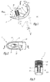
- a femoral component of a unicompartimentale prosthesis 1 which has a generally cup-shaped, with a convex outer face 2 and an inner face 3 of substantially concave profile.
- the convex outer surface 2 of the femoral component 1 substantially reproduces the anatomy of an external or internal femoral condyle, because it is intended to reproduce the articular kinematics of the knee by cooperating with the tibial component.
- the inner face 3 of the femoral component 1 comprises three distinct flat surfaces 11, 12, 13, which are able to bear against corresponding sections of a femoral condyle.
- the surfaces 11 and 13 can be described respectively as distal and posterior bearing surfaces, while the surface 12 forms an intermediate chamfer connecting the surfaces 11 and 13.
- the component 1 belongs to a prosthesis said to cut, for which the femoral condyle F requires a distal cut.
- the distal 11 and posterior flat surfaces 13 respectively define the associated planes ⁇ 11 and ⁇ 13, visible on the figure 1 .
- the normal to the plane ⁇ 11 of the surface 11 forms with the plane ⁇ 13 of the surface 13 a non-zero angle ⁇ , which in the example shown is equal to 15 °. As a variant not shown, this angle ⁇ is chosen between 10 ° and 20 °.
- the surfaces 11 and 13 do not extend in planes perpendicular to one another, but form between them an acute angle on the side of the inner face 3, as clearly visible on the figure 1 . In other words, the surface 13 is turned towards the surface 11 and the associated plane ⁇ 11, on the side of the internal face 3.
- a substantially cylindrical bone anchor pad 21 is disposed on the distal surface 11. Its central axis XX is inclined at a non-zero angle ⁇ relative to the normal to the plane ⁇ 11 of the surface 11, so that by traversing axially the stud 21 from its end connected to the surface 11 to its free end, progressively away from the surfaces 12 and 13.
- the angle ⁇ is 20 °.
- this angle ⁇ can be chosen between 15 ° and 25 °, or preferably between 15 ° and 20 °.
- the angle ⁇ is chosen strictly less than the angle ⁇ : in this way, the axis XX is inclined with respect to the plane ⁇ 13 of the surface 13, and the point which is referenced P on the figure 1 , defined by their intersection, is located on the side of the outer face 2.
- the angle ⁇ non-zero and strictly positive, formed between the axis XX and the surface 13, is less than or equal to 15 °.
- the bone anchor pad 21 delimits a plurality of longitudinal grooves 22, distributed around its circumference.
- a stiffness rib 23 extends from the stud 21 into a plane which is perpendicular to the surface 11 and which comprises the axis XX.
- the stiffening rib 23 extends at its base on the surface 11 and on the surface 12.
- the femoral component 1 is here symmetrical with respect to the plane of the rib 23. As a variant not shown, the femoral component may be asymmetrical.
- the surface 11 delimits a cement receiving cavity 111, configured in a bowl whose bottom is flat in the example in question.
- the posterior bearing surface 13 also delimits a cement receiving cavity 113, having a pyramidal relief.
- the depth and the extent of the pyramidal relief can vary to obtain a roughness of the cavity 113 more or less important. Thanks to its hollows and protuberances, this relief makes it possible to obtain volumes of cement improving the shear strength of the corresponding surface. In addition, during the impaction of the femoral component, the relief will help the cement to penetrate the cancellous bone for better anchoring. As variations not shown, other configurations in relief can be implemented, for example grooves.
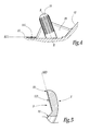
- the figure 6 shows the femoral component 1 before implantation on the bone of the femur F, more precisely in the femoral condyle.
- a surgical bone cement indicated by thickened lines, is deposited on the surfaces 11 and 13, filling the free space of the cavities 111 and 113.
- the figure 7 shows the femoral component 1 during its implantation in the femoral condyle F.
- the implantation is performed in the direction of the axis XX of the stud 21, the side of the inner face 3 of the femoral component 1, so that the bearing surfaces 11, 12 and 13 are progressively closer to corresponding femoral bone sections F1, F2 and F3, previously made.
- the presence of the angle ⁇ formed between the axis XX of the stud 21 and the plane ⁇ 13 of the surface 13 makes it possible to perform a divergent translational movement for the surface 13, with respect to the translational movement of the surface 11.
- the cement present on the surface 13 is gradually compressed against the posterior bone section F3, without being scraped.
- the stud 21 and the rib 23 facilitate the positioning and implantation of the femoral component 1 by the surgeon.
- the figure 8 represents the femoral component 1 when it is implanted in the femoral condyle F.
- the cement is well distributed between the internal face 3 of the femoral component 1 and the femoral condyle F, in particular at the level of the posterior support surface 13.
- the cement receiving cavities 111 and 113 make it possible to optimize the amount of surgical cement used during the implantation of the femoral component 1, as well as the resistance of the connection under certain constraints: the cavity 111, configured in a flat-bottomed bowl, makes it possible to obtain an optimum cement thickness for compressive stress resistance to the detriment of resistance to shear stress; while the cavity 113, with its rough relief, provides a better shear strength at the expense of the thickness of cement.
- the distal surface 11 which belongs to the inner face 3 of the component 1 and which is able to bear against a corresponding surface of a femoral condyle F, is not flat. Indeed, when the component 1 used belongs to a so-called resurfacing prosthesis, for which the femoral condyle F does not require a distal cut, then the distal surface 11 may have a curved shape, corresponding to the resurfaced complementary surface of the Femur Bone F.
- a virtual plane associated with the distal surface 11 may be defined by the peripheral line of the distal surface 11. This associated virtual plane is comparable to the plane ⁇ 11, visible on the figure 1 .
- the angle ⁇ is defined as the angle between the normal to the virtual plane associated with the surface 11 and the plane ⁇ 13 of the posterior surface 13. The surface 13 is turned towards the surface 11 and its associated virtual plane, of the side of the inner face 3.
- the femoral component 1 makes it possible to improve the positioning, the anchoring and the setting of the cement on the femoral condyle F, as well as the behavior of the femoral component 1 when it is subjected to strong stresses of flexural shear.
Landscapes
- Health & Medical Sciences (AREA)
- Orthopedic Medicine & Surgery (AREA)
- Physical Education & Sports Medicine (AREA)
- Cardiology (AREA)
- Oral & Maxillofacial Surgery (AREA)
- Transplantation (AREA)
- Engineering & Computer Science (AREA)
- Biomedical Technology (AREA)
- Heart & Thoracic Surgery (AREA)
- Vascular Medicine (AREA)
- Life Sciences & Earth Sciences (AREA)
- Animal Behavior & Ethology (AREA)
- General Health & Medical Sciences (AREA)
- Public Health (AREA)
- Veterinary Medicine (AREA)
- Prostheses (AREA)
Abstract
Description
- La présente invention concerne une prothèse unicompartimentale de genou, et plus particulièrement le composant fémoral d'une prothèse unicompartimentale de genou cimentée.
- Les prothèses unicompartimentales de genou cimentées sont implantées au niveau de l'un des compartiments fémoro-tibiaux du genou, soit interne, soit externe. La mise en place de ce genre de prothèse, appelée arthroplastie unicompartimentale, est destinée à remplacer uniquement l'un des deux compartiments du genou, interne ou externe, suivant la localisation des dommages, quelle qu'en soit l'origine (liés à l'arthrose, post-traumatiques, nécrose...), latéralisés, du côté du fémur et du côté du tibia, en utilisant un ciment osseux chirurgical.
- Une prothèse unicompartimentale du genou est généralement constituée d'un composant fémoral interne et/ou externe coopérant avec un composant tibial interne et/ou externe correspondant.
- Une prothèse unicompartimentale de genou peut être une prothèse dite à coupe ou une prothèse dite de resurfaçage, selon que le fémur nécessite ou non une coupe distale. La présente invention s'applique tant aux prothèses dites à coupe qu'aux prothèses dites de resurfaçage.
- Le profil de la face externe convexe du composant fémoral de la prothèse est tel qu'il permet une cinématique du genou prothésé proche de la cinématique originelle du genou. Le profil de la face interne du composant fémoral de la prothèse est critique pour le positionnement et la fixation du composant fémoral au fémur. En effet, après la pose d'un composant fémoral d'une prothèse unicompartimentale de genou, celui-ci est soumis à des contraintes mécaniques importantes, lesquelles sollicitent également la fixation du composant sur l'os, durant les différentes phases de fonctionnement : marche, accroupissement, etc. A ce jour, le descellement aseptique est l'une des principales causes d'échec des prothèses unicompartimentales de genou.
- Ainsi, il est essentiel que le composant fémoral d'une prothèse soit positionné avec précision sur l'os qui nécessite une réparation, puis immobilisé de manière rigide et durable.
- De manière courante, on effectue une préparation osseuse correspondant à la forme interne du composant fémoral. Par la suite, on interpose du ciment qui, pour une efficacité maximale, doit être pressurisé lors de l'implantation du composant fémoral afin de lier ce dernier au condyle fémoral lors de la prise du ciment. Par ailleurs, le positionnement est effectué à l'aide d'un plot d'ancrage osseux solidaire de la prothèse et inséré dans l'os du fémur, et par le contact entre les surfaces correspondantes osseuses et prothétiques. Ce positionnement peut également être effectué au moyen d'un élément en saillie présentant la forme d'un rail, d'une croix, etc.
-
FR-A-2 758 715 -
US-A-2006/235537 décrit un composant fémoral d'une prothèse unicompartimentale de genou, comprenant une face externe et une face interne. La face interne comporte une surface distale et une surface postérieure reliée par une surface de chanfrein. Les surfaces distale et postérieure sont chacune munie d'un plot d'ancrage osseux et sont adaptées pour être appuyées contre des surfaces osseuses fémorales correspondantes avec interposition d'un ciment. La surface d'appui postérieure est tournée vers la surface d'appui distale, avec une inclinaison d'environ 83°. L'axe central du plot d'ancrage osseux équipant la surface distale est incliné par rapport au plan de la surface d'appui postérieure d'environ 25°, plus généralement entre 20° et 30°. Une telle prothèse n'est pas entièrement satisfaisante, notamment en termes d'implantation et de comportement mécanique. - Le but de la présente invention est de prévoir un composant fémoral de prothèse permettant un positionnement correct sur l'os réséqué, ainsi qu'un ancrage et une prise du ciment améliorés, en particulier pour éviter le relâchement sous une contrainte de flexion importante.
- A cet effet, l'invention a pour objet un composant fémoral d'une prothèse unicompartimentale de genou, tel que défini à la revendication 1.
- Ainsi l'invention permet d'améliorer à la fois les étapes d'implantation du composant fémoral et de prise du ciment, de même que le comportement mécanique du composant fémoral de son côté postérieur, d'une part en créant une compression du ciment sur la surface osseuse postérieure au moyen d'un mouvement de translation divergent, et d'autre part en augmentant la résistance à la contrainte de cisaillement lors de la flexion du genou. En effet, il est essentiel que la fixation du composant fémoral d'une prothèse unicompartimentale de genou soit optimale sur l'os pour supporter les efforts d'expulsion en flexion qui sollicitent le ciment en cisaillement au niveau postérieur. L'invention permet un positionnement correct sur l'os réséqué, une limitation des efforts d'expulsion en flexion ainsi qu'une prise du ciment améliorée sur la face postérieure afin de garantir que le composant fémoral ne se descelle pas.
- D'autres caractéristiques avantageuses de l'invention, prises isolément ou en combinaison, sont spécifiées aux revendications dépendantes 2 à 11.
- Est également décrite ici une méthode chirurgicale de mise en place d'un composant fémoral telle que défini ci-dessus, cette méthode comprenant :
- une étape de préparation de l'os du fémur au niveau d'un condyle, pour réaliser au moins une coupe postérieure ;
- une étape de préparation de la face interne du composant fémoral à l'aide d'un ciment osseux chirurgical ;
- une étape d'implantation du composant fémoral selon la direction de l'axe central du plot d'ancrage osseux, dans laquelle les surfaces d'appui distale et postérieure se rapprochent progressivement des surfaces d'os respectivement distale et postérieure selon un mouvement de translation divergent, en créant une contrainte de compression du ciment sur l'os du fémur ; et
- une étape de prise du ciment.
- En outre, l'étape de préparation de l'os du fémur au niveau d'un condyle selon cette méthode peut comporter une coupe distale. Cette méthode peut également inclure une étape de pose de ciment sur la ou les coupes osseuses. De plus, cette méthode peut inclure une étape de finition et/ou de contrôle et/ou d'équilibrage et/ou de test.
- L'invention sera mieux comprise à la lecture de la description qui va suivre, donnée uniquement à titre d'exemple non limitatif et faite en se référant aux dessins sur lesquels :
- la
figure 1 est une vue en élévation d'un composant fémoral d'une prothèse unicompartimentale conforme à l'invention, - les
figures 2 et 3 sont des vues en élévation selon respectivement les flèches Il et III de lafigure 1 , - la
figure 4 est une coupe partielle selon la ligne IV-IV de lafigure 2 , - la
figure 5 est une coupe partielle selon la ligne V-V de lafigure 2 , et - les
figures 6, 7 et 8 sont des vues en élévation analogues à lafigure 1 , qui illustrent des étapes successives de l'implantation du composant fémoral sur un os du fémur. - Sur les
figures 1 à 5 est représenté un composant fémoral d'une prothèse unicompartimentale 1, qui présente une forme générale de coupelle, avec une face externe convexe 2 et une face interne 3 de profil sensiblement concave. - La face externe convexe 2 du composant fémoral 1 reproduit sensiblement l'anatomie d'un condyle fémoral externe ou interne, car elle est destinée à reproduire la cinématique articulaire du genou en coopérant avec le composant tibial.
- La face interne 3 du composant fémoral 1 comprend trois surfaces planes 11, 12, 13 distinctes, qui sont aptes à venir en appui contre des coupes correspondantes d'un condyle fémoral. Selon les conventions anatomiques, les surfaces 11 et 13 peuvent être qualifiées respectivement de surfaces d'appui distale et postérieure, tandis que la surface 12 forme un chanfrein intermédiaire reliant les surfaces 11 et 13. Dans ce cas, le composant 1 appartient à une prothèse dite à coupe, pour laquelle le condyle fémoral F nécessite une coupe distale. En outre, les surfaces planes distales 11 et postérieures 13 définissent respectivement les plans associés Δ11 et Δ13, visibles sur la
figure 1 . - La normale au plan Δ11 de la surface 11 forme avec le plan Δ13 de la surface 13 un angle α non nul, qui dans l'exemple représenté est égal à 15°. A titre de variante non représentée, cet angle α est choisi entre 10° et 20°. Ainsi, les surfaces 11 et 13 ne s'étendent pas dans des plans perpendiculaires l'un à l'autre, mais forment entre elles un angle aigu du côté de la face interne 3, comme bien visible sur la
figure 1 . Autrement dit, la surface 13 est tournée vers la surface 11 et le plan associé Δ11, du côté de la face interne 3. - Un plot d'ancrage osseux 21 sensiblement cylindrique est disposé sur la surface distale 11. Son axe central X-X est incliné d'un angle β non nul par rapport à la normale au plan Δ11 de la surface 11, de manière qu'en parcourant axialement le plot 21 depuis son extrémité liée à la surface 11 jusqu'à son extrémité libre, on s'éloigne progressivement des surfaces 12 et 13. Dans l'exemple représenté, l'angle β vaut 20°. A titre de variante non représentée, cet angle β peut être choisi entre 15° et 25°, ou de préférence entre 15° et 20°. Dans tous les cas, l'angle α est choisi strictement inférieur à l'angle β : de la sorte, l'axe X-X est incliné par rapport au plan Δ13 de la surface 13, et le point qui est référencé P sur la
figure 1 , défini par leur intersection, est situé du côté de la face externe 2. Eu égard aux valeurs des angles α et β envisagées plus haut, l'angle γ non nul et strictement positif, formé entre l'axe X-X et la surface 13, est inférieur ou égal à 15 °. - Le plot d'ancrage osseux 21 délimite une pluralité de rainures longitudinales 22, réparties sur sa circonférence. Une nervure de rigidité 23 s'étend depuis le plot 21 dans un plan qui est perpendiculaire à la surface 11 et qui comprend l'axe X-X. La nervure de rigidité 23 s'étend, à sa base, sur la surface 11 et sur la surface 12.
- Comme visible sur les
figures 2 et 3 , le composant fémoral 1 est ici symétrique par rapport au plan de la nervure 23. A titre de variante non représentée, le composant fémoral peut être asymétrique. - Comme visible sur les
figures 2 et4 , la surface 11 délimite une cavité de réception de ciment 111, configurée en cuvette dont le fond est plat dans l'exemple considéré. Comme visible sur lesfigures 3 et5 , la surface d'appui postérieure 13 délimite elle aussi une cavité de réception de ciment 113, présentant un relief pyramidal. - En pratique, la profondeur et l'étendue du relief pyramidal peuvent varier pour obtenir une rugosité de la cavité 113 plus ou moins importante. Grâce à ses creux et protubérances, ce relief permet d'obtenir des volumes de ciment améliorant la résistance au cisaillement de la surface correspondante. De plus, lors de l'impaction du composant fémoral, le relief va permettre d'aider le ciment à pénétrer dans l'os spongieux pour un meilleur ancrage. A titre de variantes non représentées, d'autres configurations en relief peuvent être mises en oeuvre, par exemple des rainures.
- La mise en place du composant fémoral 1 sur un os du fémur F va maintenant être décrite en regard des
figures 6 à 8 . - La
figure 6 montre le composant fémoral 1 avant son implantation sur l'os du fémur F, plus précisément dans le condyle fémoral. Un ciment osseux chirurgical, indiqué par des traits en surépaisseur, est déposé sur les surfaces 11 et 13, en comblant l'espace libre des cavités 111 et 113. - La
figure 7 montre le composant fémoral 1 pendant son implantation dans le condyle fémoral F. L'implantation est réalisée selon la direction de l'axe X-X du plot 21, du côté de la face interne 3 du composant fémoral 1, afin que les surfaces d'appui 11, 12 et 13 se rapprochent progressivement de coupes d'os fémorales correspondantes F1, F2 et F3, préalablement réalisées. La présence de l'angle γ formé entre l'axe X-X du plot 21 et le plan Δ13 de la surface 13 permet d'effectuer un mouvement de translation divergent pour la surface 13, par rapport au mouvement de translation de la surface 11. Ainsi le ciment présent sur la surface 13 est progressivement compressé contre la coupe d'os postérieure F3, sans être raclé. - Le plot 21 et la nervure 23 permettent de faciliter le positionnement et l'implantation du composant fémoral 1 par le chirurgien.
- La
figure 8 représente le composant fémoral 1 lorsqu'il est implanté dans le condyle fémoral F. Le ciment est bien réparti entre la face interne 3 du composant fémoral 1 et le condyle fémoral F, notamment au niveau de la surface d'appui postérieure 13. En effet, on comprend que les cavités de réception de ciment 111 et 113 permettent d'optimiser la quantité de ciment chirurgical utilisée lors de l'implantation du composant fémoral 1, ainsi que la résistance de la liaison sous certaines contraintes : la cavité 111, configurée en cuvette à fond plat, permet d'obtenir une épaisseur de ciment optimale pour la résistance à la contrainte de compression au détriment de la résistance à la contrainte de cisaillement ; tandis que la cavité 113, avec son relief rugueux, permet d'obtenir une meilleure résistance au cisaillement au détriment de l'épaisseur de ciment. - Ces deux types de cavités de réception de ciment étant combinés ici, on obtient une bonne résistance à la contrainte de compression durant l'extension, en même temps qu'une bonne résistance à la contrainte de cisaillement durant la flexion du genou prothésé.
- Selon un mode de réalisation non représenté, la surface distale 11 qui appartient à la face interne 3 du composant 1 et qui est apte à venir en appui contre une surface correspondante d'un condyle fémoral F, n'est pas plane. En effet, lorsque le composant 1 mis en oeuvre appartient à une prothèse dite de resurfaçage, pour laquelle le condyle fémoral F ne nécessite pas de coupe distale, alors la surface distale 11 peut présenter une forme courbe, correspondant à la surface complémentaire resurfacée de l'os du fémur F.
- Dans ce cas, un plan virtuel associé à la surface distale 11 peut être défini par la ligne périphérique de la surface distale 11. Ce plan virtuel associé est comparable au plan Δ11, visible sur la
figure 1 . Ainsi, l'angle α est défini comme étant l'angle entre la normale au plan virtuel associé à la surface 11 et le plan Δ13 de la surface postérieure 13. La surface 13 est tournée vers la surface 11 et son plan virtuel associé, du côté de la face interne 3. - Ainsi, le composant fémoral 1 selon l'invention permet d'améliorer le positionnement, l'ancrage et la prise du ciment sur le condyle fémoral F, de même que le comportement du composant fémoral 1 lorsqu'il est soumis à de fortes contraintes de cisaillement en flexion.
Claims (11)
- Composant fémoral (1) d'une prothèse unicompartimentale de genou, comprenant une face externe convexe (2) et une face interne (3), laquelle comporte une surface distale (11) munie d'un plot d'ancrage osseux (21) et une surface postérieure substantiellement plane (13), ces surfaces distale et postérieure (11, 13) étant adaptées pour être appuyées contre des surfaces osseuses fémorales correspondantes (F1, F3) avec interposition d'un ciment, la surface d'appui postérieure (13) étant tournée vers la surface d'appui distale (11), l'axe central (X-X) du plot d'ancrage osseux (21) étant incliné par rapport au plan (Δ13) de la surface d'appui postérieure (13), le point (P) défini par leur intersection étant situé du côté de la face externe (2), caractérisé en ce que l'axe central (X-X) du plot d'ancrage osseux (21) et le plan de la surface d'appui postérieure (13) forment un angle (γ) non nul et inférieur ou égal à 15°.
- Composant fémoral selon la revendication 1, caractérisé en ce que la surface distale (11) est substantiellement plane et adaptée pour être appuyée contre une coupe fémorale correspondante (F1) avec interposition d'un ciment.
- Composant fémoral selon l'une des revendications précédentes, caractérisé en ce que la normale au plan (Δ11) associé à la surface d'appui distale (11) forme un premier angle (α) avec le plan (Δ13) de la surface d'appui postérieure (13) et un second angle (β) avec l'axe central (X-X) du plot d'ancrage osseux (21), les premier et second angles (α, β) étant différents l'un de l'autre, le premier angle (α) étant inférieur au second angle (β).
- Composant fémoral selon la revendication 3, caractérisé en ce que le premier angle (α) est compris entre 10 ° et 20 ° et le second angle (β) est compris entre 15 et 25°.
- Composant fémoral selon l'une des revendications précédentes, caractérisé en ce la normale au plan (Δ11) associé à la surface d'appui distale (11) forme un angle (β) avec l'axe central (X-X) du plot d'ancrage osseux (21) qui est égal à 20°.
- Composant fémoral selon l'une des revendications précédentes, caractérisé en ce que les surfaces d'appui distale (11) et postérieure (13) délimitent chacune une cavité de réception de ciment (111, 113).
- Composant fémoral selon la revendication 5, caractérisé en ce que la cavité de réception de ciment (113) de la surface d'appui postérieure (13) présente une rugosité plus importante que celle de la cavité de réception de ciment (111) de la surface d'appui distale (11).
- Composant fémoral selon l'une des revendications 6 ou 7, caractérisé en ce que la cavité de réception de ciment (113) de la surface d'appui postérieure (13) présente un relief incluant au moins une pyramide et/ou au moins une rainure.
- Composant fémoral selon l'une des revendications 6, 7 ou 8, caractérisé en ce que la cavité de réception de ciment (111) de la surface d'appui distale (11) est en forme de cuvette.
- Composant fémoral selon l'une des revendications précédentes, caractérisé en ce que le plot d'ancrage osseux (21) est sensiblement cylindrique et délimite au moins une rainure longitudinale (22).
- Composant fémoral selon l'une des revendications précédentes, caractérisé en ce qu'une nervure de rigidité (23) s'étend depuis le plot d'ancrage osseux (21) dans un plan qui est perpendiculaire à la surface d'appui distale (11) et qui comprend l'axe central (X-X) du plot d'ancrage osseux (21).
Applications Claiming Priority (1)
| Application Number | Priority Date | Filing Date | Title |
|---|---|---|---|
| FR1053913A FR2960145B1 (fr) | 2010-05-20 | 2010-05-20 | Composant femoral d'une prothese unicompartimentale de genou |
Publications (2)
| Publication Number | Publication Date |
|---|---|
| EP2387974A1 true EP2387974A1 (fr) | 2011-11-23 |
| EP2387974B1 EP2387974B1 (fr) | 2013-05-01 |
Family
ID=43415303
Family Applications (1)
| Application Number | Title | Priority Date | Filing Date |
|---|---|---|---|
| EP20110166390 Not-in-force EP2387974B1 (fr) | 2010-05-20 | 2011-05-17 | Composant fémoral d'une prothèse unicompartimentale de genou |
Country Status (2)
| Country | Link |
|---|---|
| EP (1) | EP2387974B1 (fr) |
| FR (1) | FR2960145B1 (fr) |
Citations (4)
| Publication number | Priority date | Publication date | Assignee | Title |
|---|---|---|---|---|
| FR2758715A1 (fr) | 1997-01-24 | 1998-07-31 | Tornier Sa | Prothese de condyle femoral |
| FR2836821A1 (fr) * | 2002-03-11 | 2003-09-12 | Biomet Merck France | Prothese unicompartimentale pour genou |
| US20060235537A1 (en) | 2005-04-18 | 2006-10-19 | Accin Corporation | Unicondylar knee implant |
| FR2908040A1 (fr) * | 2006-11-06 | 2008-05-09 | Yves Girou | Ensemble d'implants femoraux pour prothese unicompartimentale du genou |
-
2010
- 2010-05-20 FR FR1053913A patent/FR2960145B1/fr not_active Expired - Fee Related
-
2011
- 2011-05-17 EP EP20110166390 patent/EP2387974B1/fr not_active Not-in-force
Patent Citations (4)
| Publication number | Priority date | Publication date | Assignee | Title |
|---|---|---|---|---|
| FR2758715A1 (fr) | 1997-01-24 | 1998-07-31 | Tornier Sa | Prothese de condyle femoral |
| FR2836821A1 (fr) * | 2002-03-11 | 2003-09-12 | Biomet Merck France | Prothese unicompartimentale pour genou |
| US20060235537A1 (en) | 2005-04-18 | 2006-10-19 | Accin Corporation | Unicondylar knee implant |
| FR2908040A1 (fr) * | 2006-11-06 | 2008-05-09 | Yves Girou | Ensemble d'implants femoraux pour prothese unicompartimentale du genou |
Also Published As
| Publication number | Publication date |
|---|---|
| EP2387974B1 (fr) | 2013-05-01 |
| FR2960145B1 (fr) | 2013-04-26 |
| FR2960145A1 (fr) | 2011-11-25 |
Similar Documents
| Publication | Publication Date | Title |
|---|---|---|
| EP2243444B1 (fr) | Dispositif de fixation à la glène d'un composant articulaire glénoïdien pour prothèse d'épaule, ainsi que prothèse d'épaule correspondante | |
| EP1510190B1 (fr) | Composant glénoidien de prothèse d'épaule et prothèse totale d'épaule incorporant un tel composant | |
| EP2385812B1 (fr) | Tige d'ancrage intra médullaire pour tête d'implant orthopédique | |
| EP1813230B1 (fr) | Ensemble d'Instrumentation chirurgicale pour poser une prothèse de cheville | |
| FR2854792A1 (fr) | Jeu d'elements prothetiques pour un ensemble prothetique tibial | |
| EP1952771A1 (fr) | Ensemble d'instrumentation chirurgicale pour poser une prothèse d'épaule | |
| EP2676637B1 (fr) | Ensemble d'implants fémoraux pour une prothèse du genou | |
| EP2604227A1 (fr) | Embase d'ancrage osseux et ensemble d'éléments incluant cette embase | |
| FR2726175A1 (fr) | Element prothetique tibial pour prothese du genou | |
| FR2780636A1 (fr) | Prothese de genou modulable | |
| EP2276427B1 (fr) | Prothèse d'articulation trapézo-métacarpienne | |
| WO2010023399A1 (fr) | Ensemble d'ancillaires pour implanter une prothese de genou | |
| FR2781363A1 (fr) | Cupule de cotyle pour prothese articulaire de hanche | |
| EP3361993B1 (fr) | Implant condylien pour prothese de genou | |
| EP2387974B1 (fr) | Composant fémoral d'une prothèse unicompartimentale de genou | |
| FR2960418A1 (fr) | Ensemble glenoidien pour prothese d'epaule | |
| FR2970411A1 (fr) | Element d'ancrage permettant l'ancrage a un os d'une piece articulaire d'une prothese d'articulation | |
| FR2728160A1 (fr) | Systeme de prothese de hanche a tiges cimentees et sans ciment utilisant une rape universelle | |
| FR2913591A1 (fr) | Prothese totale du genou, du type dit "postero-stabilisee" | |
| EP0605337A1 (fr) | Endo-prothèse totale de genou et éléments d'essai pour pose de cette dernière | |
| FR2630639A1 (fr) | Dispositif de prothese partielle du genou | |
| FR2896984A1 (fr) | Prothese cotyloidienne et son procede pour une implantation sans ciment. | |
| EP2491893B1 (fr) | Implant de reprise fémorale et ancillaire de mise en oeuvre chirurgicale | |
| FR3099363A3 (fr) | Tige fémorale de prothèse de hanche | |
| EP2617394B1 (fr) | Implant tibial pour une prothèse de genou unicompartimentale |
Legal Events
| Date | Code | Title | Description |
|---|---|---|---|
| AK | Designated contracting states |
Kind code of ref document: A1 Designated state(s): AL AT BE BG CH CY CZ DE DK EE ES FI FR GB GR HR HU IE IS IT LI LT LU LV MC MK MT NL NO PL PT RO RS SE SI SK SM TR |
|
| AX | Request for extension of the european patent |
Extension state: BA ME |
|
| PUAI | Public reference made under article 153(3) epc to a published international application that has entered the european phase |
Free format text: ORIGINAL CODE: 0009012 |
|
| 17P | Request for examination filed |
Effective date: 20111223 |
|
| GRAP | Despatch of communication of intention to grant a patent |
Free format text: ORIGINAL CODE: EPIDOSNIGR1 |
|
| RIC1 | Information provided on ipc code assigned before grant |
Ipc: A61F 2/38 20060101AFI20121026BHEP Ipc: A61F 2/00 20060101ALN20121026BHEP Ipc: A61F 2/30 20060101ALN20121026BHEP |
|
| RAP1 | Party data changed (applicant data changed or rights of an application transferred) |
Owner name: TORNIER |
|
| GRAS | Grant fee paid |
Free format text: ORIGINAL CODE: EPIDOSNIGR3 |
|
| GRAA | (expected) grant |
Free format text: ORIGINAL CODE: 0009210 |
|
| AK | Designated contracting states |
Kind code of ref document: B1 Designated state(s): AL AT BE BG CH CY CZ DE DK EE ES FI FR GB GR HR HU IE IS IT LI LT LU LV MC MK MT NL NO PL PT RO RS SE SI SK SM TR |
|
| REG | Reference to a national code |
Ref country code: GB Ref legal event code: FG4D Free format text: NOT ENGLISH |
|
| REG | Reference to a national code |
Ref country code: AT Ref legal event code: REF Ref document number: 609404 Country of ref document: AT Kind code of ref document: T Effective date: 20130515 Ref country code: CH Ref legal event code: EP |
|
| REG | Reference to a national code |
Ref country code: IE Ref legal event code: FG4D Free format text: LANGUAGE OF EP DOCUMENT: FRENCH |
|
| 111Z | Information provided on other rights and legal means of execution |
Free format text: AL AT BE BG CH CY CZ DE DK EE ES FI FR GB GR HR HU IE IS IT LT LU LV MC MK MT NL NO PL PT RO RS SE SI SK SM TR Effective date: 20130125 |
|
| REG | Reference to a national code |
Ref country code: DE Ref legal event code: R096 Ref document number: 602011001509 Country of ref document: DE Effective date: 20130627 |
|
| PGFP | Annual fee paid to national office [announced via postgrant information from national office to epo] |
Ref country code: IE Payment date: 20130527 Year of fee payment: 3 |
|
| PGFP | Annual fee paid to national office [announced via postgrant information from national office to epo] |
Ref country code: FR Payment date: 20130606 Year of fee payment: 3 |
|
| REG | Reference to a national code |
Ref country code: AT Ref legal event code: MK05 Ref document number: 609404 Country of ref document: AT Kind code of ref document: T Effective date: 20130501 |
|
| REG | Reference to a national code |
Ref country code: NL Ref legal event code: VDEP Effective date: 20130501 |
|
| REG | Reference to a national code |
Ref country code: LT Ref legal event code: MG4D |
|
| PG25 | Lapsed in a contracting state [announced via postgrant information from national office to epo] |
Ref country code: LT Free format text: LAPSE BECAUSE OF FAILURE TO SUBMIT A TRANSLATION OF THE DESCRIPTION OR TO PAY THE FEE WITHIN THE PRESCRIBED TIME-LIMIT Effective date: 20130501 Ref country code: SE Free format text: LAPSE BECAUSE OF FAILURE TO SUBMIT A TRANSLATION OF THE DESCRIPTION OR TO PAY THE FEE WITHIN THE PRESCRIBED TIME-LIMIT Effective date: 20130501 Ref country code: AT Free format text: LAPSE BECAUSE OF FAILURE TO SUBMIT A TRANSLATION OF THE DESCRIPTION OR TO PAY THE FEE WITHIN THE PRESCRIBED TIME-LIMIT Effective date: 20130501 Ref country code: IS Free format text: LAPSE BECAUSE OF FAILURE TO SUBMIT A TRANSLATION OF THE DESCRIPTION OR TO PAY THE FEE WITHIN THE PRESCRIBED TIME-LIMIT Effective date: 20130901 Ref country code: GR Free format text: LAPSE BECAUSE OF FAILURE TO SUBMIT A TRANSLATION OF THE DESCRIPTION OR TO PAY THE FEE WITHIN THE PRESCRIBED TIME-LIMIT Effective date: 20130802 Ref country code: ES Free format text: LAPSE BECAUSE OF FAILURE TO SUBMIT A TRANSLATION OF THE DESCRIPTION OR TO PAY THE FEE WITHIN THE PRESCRIBED TIME-LIMIT Effective date: 20130812 Ref country code: PT Free format text: LAPSE BECAUSE OF FAILURE TO SUBMIT A TRANSLATION OF THE DESCRIPTION OR TO PAY THE FEE WITHIN THE PRESCRIBED TIME-LIMIT Effective date: 20130902 Ref country code: SI Free format text: LAPSE BECAUSE OF FAILURE TO SUBMIT A TRANSLATION OF THE DESCRIPTION OR TO PAY THE FEE WITHIN THE PRESCRIBED TIME-LIMIT Effective date: 20130501 Ref country code: NO Free format text: LAPSE BECAUSE OF FAILURE TO SUBMIT A TRANSLATION OF THE DESCRIPTION OR TO PAY THE FEE WITHIN THE PRESCRIBED TIME-LIMIT Effective date: 20130801 Ref country code: FI Free format text: LAPSE BECAUSE OF FAILURE TO SUBMIT A TRANSLATION OF THE DESCRIPTION OR TO PAY THE FEE WITHIN THE PRESCRIBED TIME-LIMIT Effective date: 20130501 |
|
| PG25 | Lapsed in a contracting state [announced via postgrant information from national office to epo] |
Ref country code: PL Free format text: LAPSE BECAUSE OF FAILURE TO SUBMIT A TRANSLATION OF THE DESCRIPTION OR TO PAY THE FEE WITHIN THE PRESCRIBED TIME-LIMIT Effective date: 20130501 Ref country code: RS Free format text: LAPSE BECAUSE OF FAILURE TO SUBMIT A TRANSLATION OF THE DESCRIPTION OR TO PAY THE FEE WITHIN THE PRESCRIBED TIME-LIMIT Effective date: 20130501 Ref country code: CY Free format text: LAPSE BECAUSE OF FAILURE TO SUBMIT A TRANSLATION OF THE DESCRIPTION OR TO PAY THE FEE WITHIN THE PRESCRIBED TIME-LIMIT Effective date: 20130501 Ref country code: BG Free format text: LAPSE BECAUSE OF FAILURE TO SUBMIT A TRANSLATION OF THE DESCRIPTION OR TO PAY THE FEE WITHIN THE PRESCRIBED TIME-LIMIT Effective date: 20130801 Ref country code: HR Free format text: LAPSE BECAUSE OF FAILURE TO SUBMIT A TRANSLATION OF THE DESCRIPTION OR TO PAY THE FEE WITHIN THE PRESCRIBED TIME-LIMIT Effective date: 20130501 |
|
| BERE | Be: lapsed |
Owner name: TORNIER Effective date: 20130531 |
|
| PG25 | Lapsed in a contracting state [announced via postgrant information from national office to epo] |
Ref country code: LV Free format text: LAPSE BECAUSE OF FAILURE TO SUBMIT A TRANSLATION OF THE DESCRIPTION OR TO PAY THE FEE WITHIN THE PRESCRIBED TIME-LIMIT Effective date: 20130501 |
|
| PG25 | Lapsed in a contracting state [announced via postgrant information from national office to epo] |
Ref country code: MC Free format text: LAPSE BECAUSE OF FAILURE TO SUBMIT A TRANSLATION OF THE DESCRIPTION OR TO PAY THE FEE WITHIN THE PRESCRIBED TIME-LIMIT Effective date: 20130501 Ref country code: DK Free format text: LAPSE BECAUSE OF FAILURE TO SUBMIT A TRANSLATION OF THE DESCRIPTION OR TO PAY THE FEE WITHIN THE PRESCRIBED TIME-LIMIT Effective date: 20130501 Ref country code: EE Free format text: LAPSE BECAUSE OF FAILURE TO SUBMIT A TRANSLATION OF THE DESCRIPTION OR TO PAY THE FEE WITHIN THE PRESCRIBED TIME-LIMIT Effective date: 20130501 Ref country code: CZ Free format text: LAPSE BECAUSE OF FAILURE TO SUBMIT A TRANSLATION OF THE DESCRIPTION OR TO PAY THE FEE WITHIN THE PRESCRIBED TIME-LIMIT Effective date: 20130501 Ref country code: SK Free format text: LAPSE BECAUSE OF FAILURE TO SUBMIT A TRANSLATION OF THE DESCRIPTION OR TO PAY THE FEE WITHIN THE PRESCRIBED TIME-LIMIT Effective date: 20130501 |
|
| PG25 | Lapsed in a contracting state [announced via postgrant information from national office to epo] |
Ref country code: IT Free format text: LAPSE BECAUSE OF FAILURE TO SUBMIT A TRANSLATION OF THE DESCRIPTION OR TO PAY THE FEE WITHIN THE PRESCRIBED TIME-LIMIT Effective date: 20130501 Ref country code: BE Free format text: LAPSE BECAUSE OF NON-PAYMENT OF DUE FEES Effective date: 20130531 Ref country code: NL Free format text: LAPSE BECAUSE OF FAILURE TO SUBMIT A TRANSLATION OF THE DESCRIPTION OR TO PAY THE FEE WITHIN THE PRESCRIBED TIME-LIMIT Effective date: 20130501 Ref country code: RO Free format text: LAPSE BECAUSE OF FAILURE TO SUBMIT A TRANSLATION OF THE DESCRIPTION OR TO PAY THE FEE WITHIN THE PRESCRIBED TIME-LIMIT Effective date: 20130501 |
|
| PLBE | No opposition filed within time limit |
Free format text: ORIGINAL CODE: 0009261 |
|
| STAA | Information on the status of an ep patent application or granted ep patent |
Free format text: STATUS: NO OPPOSITION FILED WITHIN TIME LIMIT |
|
| 26N | No opposition filed |
Effective date: 20140204 |
|
| REG | Reference to a national code |
Ref country code: DE Ref legal event code: R097 Ref document number: 602011001509 Country of ref document: DE Effective date: 20140204 |
|
| PGFP | Annual fee paid to national office [announced via postgrant information from national office to epo] |
Ref country code: DE Payment date: 20130513 Year of fee payment: 3 |
|
| REG | Reference to a national code |
Ref country code: DE Ref legal event code: R119 Ref document number: 602011001509 Country of ref document: DE |
|
| REG | Reference to a national code |
Ref country code: CH Ref legal event code: PL |
|
| PG25 | Lapsed in a contracting state [announced via postgrant information from national office to epo] |
Ref country code: LI Free format text: LAPSE BECAUSE OF NON-PAYMENT OF DUE FEES Effective date: 20140531 Ref country code: CH Free format text: LAPSE BECAUSE OF NON-PAYMENT OF DUE FEES Effective date: 20140531 |
|
| REG | Reference to a national code |
Ref country code: IE Ref legal event code: MM4A |
|
| PG25 | Lapsed in a contracting state [announced via postgrant information from national office to epo] |
Ref country code: MT Free format text: LAPSE BECAUSE OF FAILURE TO SUBMIT A TRANSLATION OF THE DESCRIPTION OR TO PAY THE FEE WITHIN THE PRESCRIBED TIME-LIMIT Effective date: 20130501 |
|
| REG | Reference to a national code |
Ref country code: FR Ref legal event code: ST Effective date: 20150130 |
|
| REG | Reference to a national code |
Ref country code: DE Ref legal event code: R119 Ref document number: 602011001509 Country of ref document: DE Effective date: 20141202 |
|
| PG25 | Lapsed in a contracting state [announced via postgrant information from national office to epo] |
Ref country code: DE Free format text: LAPSE BECAUSE OF NON-PAYMENT OF DUE FEES Effective date: 20141202 Ref country code: IE Free format text: LAPSE BECAUSE OF NON-PAYMENT OF DUE FEES Effective date: 20140517 |
|
| PG25 | Lapsed in a contracting state [announced via postgrant information from national office to epo] |
Ref country code: SM Free format text: LAPSE BECAUSE OF FAILURE TO SUBMIT A TRANSLATION OF THE DESCRIPTION OR TO PAY THE FEE WITHIN THE PRESCRIBED TIME-LIMIT Effective date: 20130501 Ref country code: FR Free format text: LAPSE BECAUSE OF NON-PAYMENT OF DUE FEES Effective date: 20140602 |
|
| PG25 | Lapsed in a contracting state [announced via postgrant information from national office to epo] |
Ref country code: TR Free format text: LAPSE BECAUSE OF FAILURE TO SUBMIT A TRANSLATION OF THE DESCRIPTION OR TO PAY THE FEE WITHIN THE PRESCRIBED TIME-LIMIT Effective date: 20130501 |
|
| PG25 | Lapsed in a contracting state [announced via postgrant information from national office to epo] |
Ref country code: MK Free format text: LAPSE BECAUSE OF FAILURE TO SUBMIT A TRANSLATION OF THE DESCRIPTION OR TO PAY THE FEE WITHIN THE PRESCRIBED TIME-LIMIT Effective date: 20130501 Ref country code: HU Free format text: LAPSE BECAUSE OF FAILURE TO SUBMIT A TRANSLATION OF THE DESCRIPTION OR TO PAY THE FEE WITHIN THE PRESCRIBED TIME-LIMIT; INVALID AB INITIO Effective date: 20110517 Ref country code: LU Free format text: LAPSE BECAUSE OF NON-PAYMENT OF DUE FEES Effective date: 20130517 |
|
| GBPC | Gb: european patent ceased through non-payment of renewal fee |
Effective date: 20150517 |
|
| PG25 | Lapsed in a contracting state [announced via postgrant information from national office to epo] |
Ref country code: GB Free format text: LAPSE BECAUSE OF NON-PAYMENT OF DUE FEES Effective date: 20150517 |
|
| PG25 | Lapsed in a contracting state [announced via postgrant information from national office to epo] |
Ref country code: AL Free format text: LAPSE BECAUSE OF FAILURE TO SUBMIT A TRANSLATION OF THE DESCRIPTION OR TO PAY THE FEE WITHIN THE PRESCRIBED TIME-LIMIT Effective date: 20130501 |