EP2387902A1 - Bauteil und Vorrichtung zum Halten von Bandabschnitten - Google Patents
Bauteil und Vorrichtung zum Halten von Bandabschnitten Download PDFInfo
- Publication number
- EP2387902A1 EP2387902A1 EP11356007A EP11356007A EP2387902A1 EP 2387902 A1 EP2387902 A1 EP 2387902A1 EP 11356007 A EP11356007 A EP 11356007A EP 11356007 A EP11356007 A EP 11356007A EP 2387902 A1 EP2387902 A1 EP 2387902A1
- Authority
- EP
- European Patent Office
- Prior art keywords
- plane
- portions
- branches
- band
- parts
- Prior art date
- Legal status (The legal status is an assumption and is not a legal conclusion. Google has not performed a legal analysis and makes no representation as to the accuracy of the status listed.)
- Withdrawn
Links
- 230000001186 cumulative effect Effects 0.000 claims description 12
- 238000012423 maintenance Methods 0.000 claims description 10
- 210000000707 wrist Anatomy 0.000 claims description 4
- 210000003414 extremity Anatomy 0.000 description 7
- 239000000463 material Substances 0.000 description 6
- 208000031968 Cadaver Diseases 0.000 description 5
- 239000000470 constituent Substances 0.000 description 4
- 238000005452 bending Methods 0.000 description 3
- 239000010985 leather Substances 0.000 description 2
- 239000004033 plastic Substances 0.000 description 2
- 230000002411 adverse Effects 0.000 description 1
- 238000005553 drilling Methods 0.000 description 1
- 239000010410 layer Substances 0.000 description 1
- 239000002184 metal Substances 0.000 description 1
- 239000002356 single layer Substances 0.000 description 1
- 239000002023 wood Substances 0.000 description 1
- 210000002268 wool Anatomy 0.000 description 1
Images


Classifications
-
- A—HUMAN NECESSITIES
- A41—WEARING APPAREL
- A41F—GARMENT FASTENINGS; SUSPENDERS
- A41F15/00—Shoulder or like straps
- A41F15/02—Means for retaining the straps in position
-
- F—MECHANICAL ENGINEERING; LIGHTING; HEATING; WEAPONS; BLASTING
- F16—ENGINEERING ELEMENTS AND UNITS; GENERAL MEASURES FOR PRODUCING AND MAINTAINING EFFECTIVE FUNCTIONING OF MACHINES OR INSTALLATIONS; THERMAL INSULATION IN GENERAL
- F16B—DEVICES FOR FASTENING OR SECURING CONSTRUCTIONAL ELEMENTS OR MACHINE PARTS TOGETHER, e.g. NAILS, BOLTS, CIRCLIPS, CLAMPS, CLIPS OR WEDGES; JOINTS OR JOINTING
- F16B7/00—Connections of rods or tubes, e.g. of non-circular section, mutually, including resilient connections
- F16B7/04—Clamping or clipping connections
- F16B7/044—Clamping or clipping connections for rods or tubes being in angled relationship
- F16B7/048—Clamping or clipping connections for rods or tubes being in angled relationship for rods or for tubes without using the innerside thereof
- F16B7/0493—Clamping or clipping connections for rods or tubes being in angled relationship for rods or for tubes without using the innerside thereof forming a crossed-over connection
Definitions
- the holding element is constituted by a single rigid body making it possible to maintain frictionally crossed several portions of band (s) in a chosen place on them, along two axes whose angle between them is defined by the shape of the rigid body, maintaining a parallelism between the planes defined by the strip portions (s) at their entry on the holding element and at their output of the holding element.
- the holding device comprises the holding member and the band portions (s).
- the present invention is particularly intended for the clothing field.
- the systems commonly used to maintain cross several portions of tape (s) in a selected location on them, along two axes, maintaining a parallelism between the plans defined by the parts of tape (s) at their entry on the element holding and at their output from the holding element is perforate the band parts (s), or pinch them, or require a scratch type fastening system.
- a person skilled in the art would think of creating a body encompassing the portions of the band (s) at their intersection.
- a simple ring is sometimes used to keep cross band parts (s) without drilling, pinching or require additional fastening system.
- the document US2835010 discloses a device for holding web portions (s) for flexible webs, said web portions being crossed.
- This document describes and illustrates at least one holding element having two branches in a first plane and two branches in a second plane, whose projection forms a rhombus, the square being a particular case of rhombus, these branches being connected by elements of junction.
- Flexible band portions are passed between the branches to be maintained.
- the maintenance of these portions of flexible band (s) is based on a spacing between the branches of the first plane and those of the second plane which is less than the cumulative thickness of the strip portions (s), so at least one of the bands passing through the element will be deformed ( fig.18 ), this deformation allowing the maintenance of the device.
- the tape indeed makes a course with several changes of direction passing under a first branch, then over the other band it crosses and finally under a second branch.
- the band is thus pinched twice thanks to the reduced spacing between the branches.
- the part of the band which crosses it has a width slightly smaller than the spacing between the branches.
- the element and the device according to the invention avoids any piercing or pinching of the strip portions (s), or any additional fastening system type scratch. It is close to a system that includes the parts of the band (s) at their intersection to maintain them; but in the element according to the invention, the rigid body only surrounds part of the strip portions (s) by contributing each of the strip portions (s) to the holding system.
- the document US2835010 is the document of the state of the art closest to the element and the device according to the invention.
- the document US2835010 does not describe any holding member having at least three branches in a first plane, at least three branches in a second plane and at least six connecting portions for connecting the branches of the first plane to the branches of the second plane.
- a person skilled in the art can not infer these characteristics from the document.
- the holding element of the device according to the invention also consists of a single rigid body, consisting of two first branches, two second branches and four connection parts, connecting the ends of the branches of the foreground to the ends of the branches of the second plane; the set of segments that connect the ends of the same branch constituting, by projection, a quadrilateral.
- the document US2835010 discloses no holding device for keeping two band portions (s) crossed in two parallel planes, that is to say without bending or deformation of these band portions (s).
- the device for holding two web portions does not rely on a deformation of the web portions but on a substantial rigidity of these web portions.
- This substantial rigidity makes it possible to guarantee the necessary friction between the portions of the band (s) crossing each other as well as the necessary friction with the four connecting parts and the two branches along which these band portions (s) pass.
- the document holding device US2835010 having a functional vocation and being based on a deformation parts of tape (s), it explicitly encourages the skilled person to think in terms of flexible bands. It is also explicitly a device for maintaining flexible bands that can easily undergo deformation. This document US2835010 thus diverts from the outset the skilled person of the claimed solution.
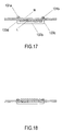
- the cumulative thickness of the two portions of intersecting web (s) is substantially equal to the length of the connecting portions of the rigid body (s) ( fig.17 ).
- Each of the two strip portions (s) thus crosses this holding element in a single plane; these two planes are substantially parallel to each other and substantially parallel, on the one hand, to the plane defined by the ends of the first branches and, on the other hand, to the plane defined by the ends of the second branches.
- the document US2835010 encourages pinching the tape overlays to deform at least one of these web portions.
- the holding device of this document is based on this band distortion. Therefore, this document explicitly encourages the skilled person to limit the space between the branches to ensure better support. This document therefore diverts from the outset the skilled person of the claimed solution.
- the width of the two web portions is substantially equal to the spacing between the branches so as to define precisely the angle according to which cross the band portions (s) and so as to increase the friction between the band portions (s) and the holding member.
- the device for holding two band portions according to the invention makes it possible to place these two band portions in the holding element without deforming them. It suffices to place the first band inside the holding element and then to slide the second band in one and the same plane, between the band previously set up and the two branches parallel to this band part. Similarly, in order to adjust the positioning of the strip portions (s) in the holding member simply slide them. The positioning of the band portions in the holding element of the device according to the invention and their repositioning is therefore simpler, faster.
- this positioning and repositioning without deformation of the web portions also makes it possible to damage only very little the web portions.
- These band parts (s) can thus be made of materials whose surface is relatively fragile, such as leather.
- the document holding device US2835010 is approached in a functional way, without it being question of the wear or the aesthetics of the bands, a person skilled in the art is not led to question these questions.
- the device for holding two portions of band (s) allows, for example, for example to maintain a band around the neck, waist, or wrist, to form a belt, a tie or a bracelet. Two ends of the band portions thus meet behind the neck, waist or wrist; the other two ends of these band portions being free, that is to say that they do not undergo any traction force.
- the band parts may have a tendency to discard and on the other hand the two free ends of these band portions (s) tend to be positioned vertically to the planes defined by the branches.
- the holding element in order to maintain at least three web portions, consists of a single rigid body, composed of at least three first branches, the ends of which define a first plane, at least three second branches, the ends of which define a second plane and at least six connecting portions, substantially orthogonal to the planes defined by the ends of the branches, connecting the ends of the branches of the first plane to the ends of the branches of the second plane; two of these connecting portions whose ends of the first plane are connected by one and the same branch can not have the ends of the second plane connected by one and the same branch of this second plane, and vice versa, two of these connecting portions whose ends of the second plan are connected by the same branch can not have the ends of the foreground connected by the same branch of this foreground; the set of segments connecting two ends of the same branch is, by projection, one or more quadrilaterals.
- the branches and the connecting portions may be substantially linear elements.
- band parts s
- the holding element comprising band parts (s) and the holding element, the band parts being held by this element.
- Each band portion contributes to the maintenance of the system and is maintained during its passage through the rigid body by at least four connecting parts and at least two branches.
- the device comprises these two band portions and a holding element, which consists of a single rigid body composed of two first branches, the ends of which define a first plane, of two second branches, the ends of which define a second plane and four connecting parts, substantially orthogonal to the planes defined by the ends of the branches, connecting the ends of the branches of the first plane to the ends branches of the background; the set of segments which connect the ends of the same branch constitutes, by projection, a quadrilateral; each band portion (s) has a substantially constant width and a substantially constant thickness; the cumulative thickness of the portions of band (s) intersecting is substantially equal to the length of the connecting portions of the rigid body.
- each of the strip portions (s) is substantially equal to the distance between the plane defined by the ends of the portions of connecting one side of the considered band portion and the plane defined by the ends of the connecting portions on the other side of the considered band portion.
- the band portions (s) are substantially rigid.
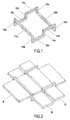
- the element according to the invention consists of a single rigid body, composed of three first branches (11a, 11b and 11c), the ends of which define a first plane (1), of three second branches (12a, 12b and 12c), the ends of which define a second plane (2) and six connecting portions (13a, 13b, 13c, 13d, 13e, 13f) substantially orthogonal to the planes (1 and 2) defined by the ends of the branches (11a 11b, 11c, 12a, 12b, 12c), connecting the ends of the legs (11a, 11b, 11c) of the first plane (1) to the ends of the legs (12a, 12b, 12c) of the second plane (2) ; two of these connecting portions (13a, 13b, 13c, 13d, 13e, 13f) whose ends of the first plane (1) are connected by the same branch do not have the ends of the second plane (2) connected by the same branch of this second plane, and conversely, two of these connecting portions (13a, 13
- the branches (11a, 11b, 11c, 12a, 12b, 12c) and the connecting portions (13a, 13b, 13c, 13d, 13e, 13f) are substantially linear elements.
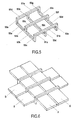
- band portion A, B, C
- the band portions A, B, C
- Each band portion contributes to the maintenance of the system and is maintained during its passage through the rigid body by two branches and at least four connecting parts.
- Each of the strip portions (A, B, C) has a substantially constant width and a substantially constant thickness.
- the thickness of the strip portions (B) and (C) is substantially equal and the cumulative thickness of the strip portions (s) intersecting is substantially equal to the length of the connecting portions of the rigid body.
- the cumulative thickness of the strip portions (s) A and B is substantially equal to the length of the connecting portions (13a, 13b, 13c, 13d, 13e and 13f).
- each of the strip portions is substantially equal to the distance between the plane (3) defined by the ends of the connecting portions on one side of the strip portion considered and the plane (4) defined by the ends of the connecting portions on the other side of the considered band portion.
- the element according to the invention consists of a single rigid body composed of five first limbs (51a, 51b, 51c, 51d, 51e), the ends of which define a first plane (1), five second legs (52a, 52b, 52c, 52d, 52e), the ends of which define a second plane (2) and eight connecting portions (53a, 53b, 53c, 53d, 53e, 53f, 53g, 53h), substantially orthogonal to the planes (1 and 2) defined by the ends of the limbs (51a, 51b, 51c, 51d, 51e, 52a, 52b, 52c, 52d, 52e), connecting the ends of the limbs (51a, 51b, 51c).
- the branches (51a, 51b, 51c, 51d, 51e, 52a, 52b, 52c, 52d, 52e) and the connecting portions (53a, 53b, 53c, 53d, 53e, 53f, 53g, 53h) are substantially linear elements. .
- band (s) D, E, F, G
- band parts D, E, F, G
- Each band portion contributes to the maintenance of the system and is maintained as it passes through the rigid body by three branches and five connecting parts.
- Each of the strip portions (D, E, F, G) has a substantially constant width and a substantially constant thickness.
- the thickness of the strip portions (s) D and E is substantially equal, the thickness of the strip portions (s) F and G is substantially equal and the cumulative thickness of the strip portions (s) intersecting is substantially equal to the length of the connecting parts of the rigid body.
- the cumulative thickness of the strip portions (s) D and F is substantially equal to the length of the connecting portions (53a, 53b, 53c, 53d, 53e, 53f, 53g, 53h).
- each of the band portions (D, E, F, G) is substantially equal to the distance between the plane (3) defined by the ends of the connecting portions on one side of the band portion considered and the plane (4) defined by the ends of the connecting portions on the other side of the band portion under consideration.
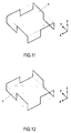
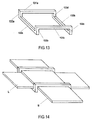
- the element according to the invention consists of a single rigid body, consisting of four first branches (91a, 91b, 91c, 91d), the ends of which define a first plane (1), four second branches (92a, 92b, 92c, 92d), the ends of which define a second plane (2) and eight connecting portions (93a, 93b, 93c, 93d, 93e, 93f, 93g, 93h), substantially orthogonal to the planes (1 and 2) defined by the ends of the limbs (91a, 91b, 91c, 91d, 92a, 92b, 92c, 92d), connecting the ends of the limbs (91a, 91b, 91c, 91d) of the first plane (1) at the ends of the branches (92a, 92b, 92c, 92d) of the second plane (2); two of these connecting parts (93a, 93b, 93
- the branches 91a, 91b, 91c, 91d, 92a, 92b, 92c, 92d) and the connecting portions (93a, 93b, 93c, 93d, 93e, 93f, 93g, 93h) are substantially linear elements.
- band (s) H, I, J, K
- band parts H, I, J, K
- Each band portion contributes to the maintenance of the system and is maintained during its passage through the rigid body by two branches and five connecting portions.
- Each band part crosses two parts of band (s) along the other axis, passing on one below and the other.
- the band portions (s) therefore do not remain in the same plane during their passage through the element, but the part of this band part at its entry into this holding element is substantially parallel to the part of this part of strip at its output from this holding element.
- Each of the strip portions (H, I, J, K) has a substantially constant width and a substantially constant thickness.
- the thickness of the strip portions H and I is substantially equal, the thickness of the strip portions J and K is substantially equal and the cumulative thickness of the strip portions intersecting is substantially equal to the length of the connecting parts of the rigid body.
- the cumulative thickness of the strip portions (s) H and J is substantially equal to the length of the connecting portions (93a, 93b, 93c, 93d, 93e, 93f, 93g, 93h).
- each of the strip portions (H, I, J, K) is substantially equal to the distance between the plane (3) defined by the ends of the connecting portions on one side of the strip portion considered and the plane (4) defined by the ends of the connecting portions on the other side of the band portion under consideration.
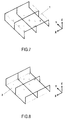
- the device according to the invention comprises two portions of strip (s) (L, M) substantially rigid and the holding member; this holding element consists of a single rigid body, composed of two first limbs (131a, 131b), the ends of which define a first plane (1), of two second limbs (132a, 132b), the ends of which define a second plane (2) and four connecting portions (133a, 133b, 133c, 133d), substantially orthogonal to the planes (1 and 2) defined by the ends of the branches (131a, 131b, 132a, 132b), connecting the ends of the branches (131a, 131b) of the first plane (1) at the ends of the branches (132a, 132b) of the second plane (2); the set of segments connecting the ends of the same branch is, by projection along the Z axis, a square; each of the two strip portions (L, M) has a substantially constant width and a substantially constant thickness; the cumulative thickness of the intersect
- each of the strip portions (L, M) is substantially equal to the distance between the plane (3) defined by the ends of the connecting portions on one side of the strip portion under consideration and the plane ( 4) defined by the ends of the connecting portions on the other side of the considered band portion.
- the branches (131a, 131b, 132a, 132b) and the connecting portions (133a, 133b, 133c, 133d) of the rigid body are substantially linear elements.
- the device can be is intended for the clothing field, in order to maintain between them one or more bands.
- the device can be implemented in the form of a band around the neck, waist, wrist, and maintained through the element; the ends of the strip being subjected to no traction force.
- rigid body a part which, under the stresses exerted by the device and on the device during its use and the introduction of the strip portions (s), undergoes a substantially zero bending, to the human eye, and do not split.
- This piece can be made of various materials such as metal, wood, plastic. Depending on the materials and the aesthetics sought, this rigid body can be molded as well as cut in the same block of material or made of welded or glued pieces. The distance between the ends of the branches is between 4mm and 200mm, and particularly between 4mm and 80mm.
- strip By strip is meant a linear and flat element.
- This band can be made of various materials such as leather, wool, jeans, plastic. It can be composed of a single layer of the chosen material but also of several and these layers can be linked together or independently.
- substantially rigid band it is possible to designate either a band whose allowed bending diameter can not be less than 5 mm without this adversely affecting the qualities of this band, ie a strip made up of several strips of flexible strips bonded together, this superposition giving it a certain rigidity, contributing to the friction of the parts of the band (s) intersecting, and conferring a certain thickness, contributing to the friction with the connecting parts and with the branches.
- branches and connecting parts of the rigid body are replaced by segments, a segment corresponding to a portion of line bounded by two points.
- the segment corresponding to a branch is defined as the connection between the ends of this branch and the segment corresponding to a connecting part is defined as the connection between the ends of this branch. connecting part.
- the set of segments corresponding to the branches not necessarily constituting, by projection along the Z axis, one or more rectangles, but quadrilateral or parallelepipedal shapes, the width of a portion of the strip, to be maintained between parts of connection, is defined by distance between the plane (3) defined by the ends of the connecting portions on one side of the considered band portion and the plane (4) defined by the ends of the connecting portions on the other side of the part of band considered.
Landscapes
- Engineering & Computer Science (AREA)
- Textile Engineering (AREA)
- Professional, Industrial, Or Sporting Protective Garments (AREA)
- Prostheses (AREA)
Applications Claiming Priority (2)
| Application Number | Priority Date | Filing Date | Title |
|---|---|---|---|
| FR1002079A FR2960269A1 (fr) | 2010-05-18 | 2010-05-18 | Element et dispositif de maintien de deux parties de bande(s). |
| FR1002494A FR2960270B1 (fr) | 2010-05-18 | 2010-06-14 | Element et dispositif de maintien de parties de bande(s). |
Publications (1)
| Publication Number | Publication Date |
|---|---|
| EP2387902A1 true EP2387902A1 (de) | 2011-11-23 |
Family
ID=44118466
Family Applications (1)
| Application Number | Title | Priority Date | Filing Date |
|---|---|---|---|
| EP11356007A Withdrawn EP2387902A1 (de) | 2010-05-18 | 2011-05-16 | Bauteil und Vorrichtung zum Halten von Bandabschnitten |
Country Status (2)
| Country | Link |
|---|---|
| EP (1) | EP2387902A1 (de) |
| FR (1) | FR2960270B1 (de) |
Citations (5)
| Publication number | Priority date | Publication date | Assignee | Title |
|---|---|---|---|---|
| DE859091C (de) * | 1948-10-02 | 1952-12-11 | Wilhelm Kramer | Klemmverbindung fuer sich kreuzende Rohre mit variablem Durchmesser |
| US2835010A (en) | 1954-05-20 | 1958-05-20 | Patrice M Bayon | Adjustable crossing piece for flexible bands |
| US3845522A (en) * | 1971-02-18 | 1974-11-05 | J Soukeras | Safe personal effects pouches and strap means for under arm or shoulder wear |
| US4406348A (en) * | 1981-12-09 | 1983-09-27 | Switlik Ii Stanley | Clip for safety harnesses |
| WO2000041857A1 (en) * | 1999-01-15 | 2000-07-20 | Gs Metals Corporation | Hookbill wire cutter |
-
2010
- 2010-06-14 FR FR1002494A patent/FR2960270B1/fr not_active Expired - Fee Related
-
2011
- 2011-05-16 EP EP11356007A patent/EP2387902A1/de not_active Withdrawn
Patent Citations (5)
| Publication number | Priority date | Publication date | Assignee | Title |
|---|---|---|---|---|
| DE859091C (de) * | 1948-10-02 | 1952-12-11 | Wilhelm Kramer | Klemmverbindung fuer sich kreuzende Rohre mit variablem Durchmesser |
| US2835010A (en) | 1954-05-20 | 1958-05-20 | Patrice M Bayon | Adjustable crossing piece for flexible bands |
| US3845522A (en) * | 1971-02-18 | 1974-11-05 | J Soukeras | Safe personal effects pouches and strap means for under arm or shoulder wear |
| US4406348A (en) * | 1981-12-09 | 1983-09-27 | Switlik Ii Stanley | Clip for safety harnesses |
| WO2000041857A1 (en) * | 1999-01-15 | 2000-07-20 | Gs Metals Corporation | Hookbill wire cutter |
Also Published As
| Publication number | Publication date |
|---|---|
| FR2960270A1 (fr) | 2011-11-25 |
| FR2960270B1 (fr) | 2014-10-10 |
Similar Documents
| Publication | Publication Date | Title |
|---|---|---|
| EP0382606B1 (de) | Verschlussring für gewellte Rohre | |
| FR2525945A1 (fr) | Cartouche de lame(s) flexible pour rasoir | |
| EP1281878A1 (de) | Gelenkzapfen zwischen zwei Teilen | |
| EP2981217B1 (de) | System zum verbinden zweier blutgefässe | |
| EP1213980A1 (de) | Vorrichtung zur positionsverriegelung eines bezüglich eines ortsfesten elements beweglichen teils | |
| FR2536804A1 (fr) | Dispositif de liaison perfectionne a assemblage et demontage rapides | |
| EP3246765B1 (de) | Zwischen-armband-verbindung für armbanduhr | |
| FR2982651A3 (fr) | Pince expansible avec tetes de machoire entrecroisees | |
| EP0962743B1 (de) | Vorrichtung zum pyrotechnischen Schneiden von nicht metallischen Stücken | |
| EP1945893B1 (de) | Eine relativbewegung zwischen zwei starren teilen gestattender mechanismus, der aber mit drehverhinderungsmitteln versehen ist | |
| FR2664242A1 (fr) | Convoyeur a bande sans fin. | |
| EP2387902A1 (de) | Bauteil und Vorrichtung zum Halten von Bandabschnitten | |
| FR2622415A1 (fr) | Bijou a elements constitutifs interchangeables | |
| EP1925227A1 (de) | Faltverschluss für Armbänder | |
| EP0115740A1 (de) | Faltverschluss für Armbänder | |
| FR2524654A1 (fr) | Dispositif de raccordement de fibres optiques et procede le mettant en oeuvre | |
| FR3054009A1 (fr) | Accessoire pour ensemble formant raccord avec systeme anti-perforation | |
| EP0187061A1 (de) | Vorrichtung zu einer gelenkigen Verbindung von zwei ergänzenden Reihen von Verbindungshaken | |
| EP0200871B1 (de) | Armband und seine Fassung | |
| FR3049319A1 (fr) | Cardan a structure simplifiee | |
| EP2525247B1 (de) | Brillengestell mit Gelenk | |
| EP0006664B1 (de) | Ein aus starren, direkt ineinandergefügten Gliedern bestehendes Armband | |
| WO2010010182A1 (fr) | Ensemble de bijoux composé d'au moins trois pièces solidarisées entre elles | |
| FR2960269A1 (fr) | Element et dispositif de maintien de deux parties de bande(s). | |
| EP4283806A2 (de) | Verbindungselement für kabelrinnenabschnitte aus drahtgitter |
Legal Events
| Date | Code | Title | Description |
|---|---|---|---|
| AK | Designated contracting states |
Kind code of ref document: A1 Designated state(s): AL AT BE BG CH CY CZ DE DK EE ES FI FR GB GR HR HU IE IS IT LI LT LU LV MC MK MT NL NO PL PT RO RS SE SI SK SM TR |
|
| AX | Request for extension of the european patent |
Extension state: BA ME |
|
| PUAI | Public reference made under article 153(3) epc to a published international application that has entered the european phase |
Free format text: ORIGINAL CODE: 0009012 |
|
| 17P | Request for examination filed |
Effective date: 20120515 |
|
| STAA | Information on the status of an ep patent application or granted ep patent |
Free format text: STATUS: THE APPLICATION IS DEEMED TO BE WITHDRAWN |
|
| 18D | Application deemed to be withdrawn |
Effective date: 20131203 |