EP2387131A2 - Brushless DC motor - Google Patents
Brushless DC motor Download PDFInfo
- Publication number
- EP2387131A2 EP2387131A2 EP11165134A EP11165134A EP2387131A2 EP 2387131 A2 EP2387131 A2 EP 2387131A2 EP 11165134 A EP11165134 A EP 11165134A EP 11165134 A EP11165134 A EP 11165134A EP 2387131 A2 EP2387131 A2 EP 2387131A2
- Authority
- EP
- European Patent Office
- Prior art keywords
- magnet
- shaft
- motor
- brushless
- hole
- Prior art date
- Legal status (The legal status is an assumption and is not a legal conclusion. Google has not performed a legal analysis and makes no representation as to the accuracy of the status listed.)
- Withdrawn
Links
- 239000011347 resin Substances 0.000 claims abstract description 28
- 229920005989 resin Polymers 0.000 claims abstract description 28
- 229920000728 polyester Polymers 0.000 claims description 2
- 238000010276 construction Methods 0.000 description 5
- 230000008878 coupling Effects 0.000 description 3
- 238000010168 coupling process Methods 0.000 description 3
- 238000005859 coupling reaction Methods 0.000 description 3
- 238000006073 displacement reaction Methods 0.000 description 3
- 230000005415 magnetization Effects 0.000 description 3
- 238000000034 method Methods 0.000 description 3
- 230000002265 prevention Effects 0.000 description 2
- 239000011230 binding agent Substances 0.000 description 1
- 238000001816 cooling Methods 0.000 description 1
- 230000003247 decreasing effect Effects 0.000 description 1
- 230000001419 dependent effect Effects 0.000 description 1
- 239000000203 mixture Substances 0.000 description 1
- 230000002093 peripheral effect Effects 0.000 description 1
- 239000000843 powder Substances 0.000 description 1
Images
Classifications
-
- H—ELECTRICITY
- H02—GENERATION; CONVERSION OR DISTRIBUTION OF ELECTRIC POWER
- H02K—DYNAMO-ELECTRIC MACHINES
- H02K1/00—Details of the magnetic circuit
- H02K1/06—Details of the magnetic circuit characterised by the shape, form or construction
- H02K1/22—Rotating parts of the magnetic circuit
- H02K1/28—Means for mounting or fastening rotating magnetic parts on to, or to, the rotor structures
- H02K1/30—Means for mounting or fastening rotating magnetic parts on to, or to, the rotor structures using intermediate parts, e.g. spiders
-
- H—ELECTRICITY
- H02—GENERATION; CONVERSION OR DISTRIBUTION OF ELECTRIC POWER
- H02K—DYNAMO-ELECTRIC MACHINES
- H02K1/00—Details of the magnetic circuit
- H02K1/06—Details of the magnetic circuit characterised by the shape, form or construction
- H02K1/22—Rotating parts of the magnetic circuit
- H02K1/27—Rotor cores with permanent magnets
- H02K1/2706—Inner rotors
- H02K1/272—Inner rotors the magnetisation axis of the magnets being perpendicular to the rotor axis
- H02K1/2726—Inner rotors the magnetisation axis of the magnets being perpendicular to the rotor axis the rotor consisting of a single magnet or two or more axially juxtaposed single magnets
- H02K1/2733—Annular magnets
-
- H—ELECTRICITY
- H02—GENERATION; CONVERSION OR DISTRIBUTION OF ELECTRIC POWER
- H02K—DYNAMO-ELECTRIC MACHINES
- H02K15/00—Processes or apparatus specially adapted for manufacturing, assembling, maintaining or repairing of dynamo-electric machines
- H02K15/02—Processes or apparatus specially adapted for manufacturing, assembling, maintaining or repairing of dynamo-electric machines of stator or rotor bodies
- H02K15/03—Processes or apparatus specially adapted for manufacturing, assembling, maintaining or repairing of dynamo-electric machines of stator or rotor bodies having permanent magnets
Definitions
- the present invention relates to a brushless DC motor provided with a rotor having a shaft and a column-shaped magnet.
- a rotor 100 of the brushless DC motor includes a shaft 104 and a column-shaped magnet 102.
- the magnet 102 is provided with a through hole 102e in the direction of a center axis, and the shaft 104 is press-fitted into the through hole 102e, so that the both members 102 and 104 are coupled.
- the magnet 102 may be broken at the time of press-fitting.
- the coupling strength between the both members 104 and 102 is decreased, so that the shaft 104 may rotate with respect to the magnet 102 with time.
- a recess 106h is formed on an outer surface of the shaft 106, and the recess 106h is filled with the resin 107 so that the relative rotation between the shaft 106 and the resin 107 can be prevented.
- an inner surface of the cylindrical magnet 105 and an outer surface of the resin 107 are both formed into a circular shape in cross section, and are configured to come into surface contact with each other, there is a possibility of displacement of the magnet 105 in the direction of rotation with respect to the resin 107 with time.
- a brushless DC motor including a rotor having a shaft and a column-shaped magnet in which a through hole is formed at a center of the magnet in the axial direction for allowing the shaft to be inserted and also allowing resin to be filled in a space between an inner wall surface of the through hole and an outer surface of the shaft, wherein the inner wall surface of the through hole of the magnet and the outer surface of the shaft are formed into shapes which can prevent relative rotation of the shaft with respect to the magnet via the resin.
- the inner wall surface of the through hole of the magnet and the outer surface of the shaft are formed into the shapes which achieve the prevention of relative rotation between the magnet and the shaft via the resin filled therebetween.
- the inner wall surface of the through hole of the magnet and the outer surface of the shaft are formed into the shapes that can prevent relative rotation of the magnet and the shaft, the prevention can be achieved efficiently without a significant cost increase.
- the through hole of the magnet is formed into a polygonal shape in cross section.
- the outline of the resin filled in the through hole of the magnet also has a polygonal column shape, so that the rotation of the magnet with respect to the resin can be reliably prevented.
- the magnet is magnetized so that a magnetic field is produced at a right angle to an outer surface of the magnet and a magnetic field is produced at a right angle to an end surface of the magnet in the axial direction.
- a driving magnet can be used as a position-detecting magnet of the brushless DC motor, and thus, the number of components can be reduced. Also, such problem that the resin filled into the through hole of the magnet enters a space between the driving magnet and the position-detecting magnet which may occur when the driving magnet and the position-detecting magnet are separate members can be prevented.
- the magnet is an isotropic bonded magnet.
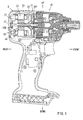
- a brushless DC motor 20 according to the embodiment is a motor used as a drive source of an impact driver 10, and is accommodated in a rear portion of a housing body 12 of the impact driver 10 as shown in FIG. 1 .
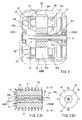
- the brushless DC motor 20 includes a rotor 30 consisted of magnet etc., and a stator 23 having drive coils 23c as shown in FIG. 2 .
- the stator 23 includes a cylindrical body (not shown) and six tooth portions 23p projecting radially inward from an inner peripheral surface of the cylindrical body, and the tooth portions 23p are each wound with the drive coil 23c via an insulating member.
- a ring-shaped electric circuit board 25 is attached to a rear end portion of the stator 23 coaxially with the stator 23, and three magnetic sensors 27 for detecting the positions of magnetic poles of the rotor 30 are arranged on a surface (front surface side) of the electric circuit board 25 at intervals of 120° in the circumferential direction.
- the rotor 30 is supported by the housing body 12 with a shaft 31 of the rotor 30 supported via bearings 32f and 32b at both ends thereof so as to be coaxial with the stator 23. Further, a motor cooling fan 33 is coaxially mounted on a front portion of the shaft 31 projecting forward from the stator 23.
- the brushless DC motor 20 is configured to rotate the rotor 30 by a motor drive circuit (not shown) which applies an electric current to the respective drive coils 23c of the stator 23 in sequence while the position of the magnetic poles of the rotor 30 are detected by the magnetic sensors 27.
- the rotor 30 includes a substantially column-shaped magnet 34 as shown in FIGS. 3A and 3B .
- a through hole 34k having a hexagonal shape in cross section is formed at a center of the magnet 34 so as to extend in the axial direction as shown in FIG. 3B .
- the shaft 31 is inserted coaxially into the through hole 34k of the magnet 34, and a space between the inner wall surface of the through hole 34k and an outer surface of the shaft 31 is filled with resin 35.
- the magnet 34 and the shaft 31 are set in a mold (not shown) in a state of being kept coaxially with each other and, in this state, the resin 35 is injected into the through hole 34k of the magnet 34. Accordingly, the magnet 34 and the shaft 31 are coupled via the resin 35.
- polyester is used as the resin.
- the through hole 34k of the magnet 34 is formed into a hexagonal shape in cross section, and the outline of the resin 35 filled in the through hole 34k of the magnet 34 also has a hexagonal column shape, so that the relative rotation of the magnet 34 with respect to the resin 35 can be prevented. Because a ridge 31t extending in the axial direction is formed on a surface of the shaft 31 as shown in FIG. 3A , it is also assured that the relative rotation between the shaft 31 and the resin 35 can be prevented.
- the magnet 34 of the rotor 30 is a permanent magnet used for both a driving magnet of the brushless DC motor 20 and a position-detecting magnet, and is formed of an isotropic bonded magnet.
- the driving magnet is a permanent magnet in which the direction of a magnetic field H is at a right angle with respect to an outer surface of the rotor 30, that is, the same as the direction of the radius of the rotor 30, and is used for driving the brushless DC motor 20.
- the position-detecting magnet is a permanent magnet in which the direction of the magnetic field H is at a right angle with respect to a rear end surface of the rotor 30, that is, the same direction as the axial direction of the rotor 30, and is used by the magnetic sensor 27 for detecting the position of the magnetic poles of the rotor 30.
- the magnet 34 is formed of the isotropic bonded magnet, two direction of magnetization (radial direction and axial direction) can be easily performed.
- the bonded magnet that constitutes the magnet 34 is molded by solidifying magnet powder with binder, and hence it has a high flexibility in shape.
- the cross-sectional shape of the through hole 34k can be made to a desired shape.
- the magnet 34 has four poles, and is provided with N-poles and S-poles at intervals of 90° in the circumferential direction. Further, as the magnet 34 is an isotropic magnet, it can be magnetized in the desired direction by being applied with a magnetic field from the outside.
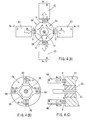
- four field coils 43 (No. 11, No. 12, No. 13, and No. 14) are arranged around the magnet 34 at intervals of 90° in the circumferential direction, and magnetic fields are applied at a right angle (radial direction) to the outer surface of the rotor 30. At this time, the electric currents flow through the respective field coils 43 such that the direction of the magnetic fields of the adjacent field coils 43 is reversed. In this way, magnetization of the driving magnet portions can be performed, as shown in FIG. 4(A) .
- four field coils 46 are arranged in the vicinity of a rear end surface of the magnet 34 at intervals of 90°, and magnetic fields are applied at a right angle (axial direction) to the rear end surface of the rotor 30, as shown in FIGS. 4(B) and 4(C) .
- the electric currents flow through the respective field coils 46 such that the direction of the magnetic fields of the adjacent field coils 46 is reversed. In this way, magnetization of the position-detecting magnet portions can be achieved.
- the magnet 34 used for both the driving magnet and the position-detecting magnet can be obtained.
- an inner wall surface of the through hole 34k of the magnet 34 and the outer surface of the shaft 31 are formed into shapes which can prevent the relative rotation between the magnet 34 and the shaft 31 via the resin 35 filled therebetween. Thus, displacement of the shaft 31 with respect to the magnet 34 with time can be prevented.
- the inner wall surface of the through hole 34k of the magnet 34 and the outer surface of the shaft 31 are formed into shapes which can prevent the relative rotation between the magnet 34 and the shaft 31.
- the relative rotation can be efficiently prevented without a significant cost increase.
- the through hole 34k of the magnet 34 is formed into a hexagonal shape in cross section, and the outline of the resin 35 filled in the through hole 34k of the magnet 34 also has a hexagonal column shape, the rotation of the magnet 34 with respect to the resin 35 can be reliably prevented.
- the magnet 34 is an isotropic magnet used for both the driving magnet and the position-detecting magnet, the number of components can be reduced. In addition, such problem that the resin 35 filed into the through hole 34k of the magnet 34 enters a space between the driving magnet and the position-detecting magnet which may occur when the driving magnet and the position-detecting magnet are separate members can be prevented.
- the magnet 34 is the isotropic bonded magnet, it is easy to machine the magnet 34 to form the through hole 34k into a desired shape.
- the invention is not limited to the embodiment described above, and may be modified without departing the scope of the invention.
- the magnet 34 having the four poles has been exemplified in the embodiment, but the number of poles of the magnet 34 can be changed as needed.
- the through hole 34k of the magnet 34 having a hexagonal cross section has been exemplified in the embodiment, but it is also possible to form the through hole 34k of the magnet 34 having a square shape in cross section or a pentagonal shape in cross section.
- the shaft 31 formed with the ridge 31t extending in the axial direction on the outer surface thereof has been exemplified in the embodiment, but it is also possible to form the shaft 31 into a square, pentagonal, or hexagonal shape in cross section.
- the brushless DC motor 20 is used in the impact driver 10, but it can be used in electric power tools other than the impact driver 10.
Landscapes
- Engineering & Computer Science (AREA)
- Power Engineering (AREA)
- Manufacturing & Machinery (AREA)
- Permanent Field Magnets Of Synchronous Machinery (AREA)
- Brushless Motors (AREA)
- Iron Core Of Rotating Electric Machines (AREA)
Abstract
Description
- This application claims priority to Japanese patent application serial number
2010-108133 - The present invention relates to a brushless DC motor provided with a rotor having a shaft and a column-shaped magnet.
- An example of a rotor of a brushless DC motor is shown in
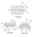
FIG. 5(A) . Arotor 100 of the brushless DC motor includes ashaft 104 and a column-shaped magnet 102. Themagnet 102 is provided with athrough hole 102e in the direction of a center axis, and theshaft 104 is press-fitted into thethrough hole 102e, so that the bothmembers hole 102e of themagnet 102 and theshaft 104 are set to achieve a high coupling strength between themagnet 102 and theshaft 104, themagnet 102 may be broken at the time of press-fitting. In contrast, if the inner diameter of thethrough hole 102e is adjusted to prevent themagnet 102 from breaking, the coupling strength between the bothmembers shaft 104 may rotate with respect to themagnet 102 with time. - In order to solve the problem, a technique for filling
resin 107 in a space between acylindrical magnet 105 and ashaft 106 and for coupling themagnet 105 with theshaft 106 as shown inFIGS. 5(B) and 5(C) is described in Japanese Laid-Open Utility Model Publication No.2-88437 6-026040 - In the technique described in Japanese Laid-Open Utility Model Publication No.
2-88437 6-026040 recess 106h is formed on an outer surface of theshaft 106, and therecess 106h is filled with theresin 107 so that the relative rotation between theshaft 106 and theresin 107 can be prevented. However, since an inner surface of thecylindrical magnet 105 and an outer surface of theresin 107 are both formed into a circular shape in cross section, and are configured to come into surface contact with each other, there is a possibility of displacement of themagnet 105 in the direction of rotation with respect to theresin 107 with time. - Thus, there is a need to effectively prevent the relative rotation between a shaft and a magnet of a rotor.
- According to one construction, there is provided a brushless DC motor including a rotor having a shaft and a column-shaped magnet in which a through hole is formed at a center of the magnet in the axial direction for allowing the shaft to be inserted and also allowing resin to be filled in a space between an inner wall surface of the through hole and an outer surface of the shaft, wherein the inner wall surface of the through hole of the magnet and the outer surface of the shaft are formed into shapes which can prevent relative rotation of the shaft with respect to the magnet via the resin.
- In this construction, the inner wall surface of the through hole of the magnet and the outer surface of the shaft are formed into the shapes which achieve the prevention of relative rotation between the magnet and the shaft via the resin filled therebetween. Thus, displacement of the shaft in the direction of rotation with respect to the magnet with time can be prevented.
- Because the inner wall surface of the through hole of the magnet and the outer surface of the shaft are formed into the shapes that can prevent relative rotation of the magnet and the shaft, the prevention can be achieved efficiently without a significant cost increase.
- According to another construction, the through hole of the magnet is formed into a polygonal shape in cross section.
- Thus, the outline of the resin filled in the through hole of the magnet also has a polygonal column shape, so that the rotation of the magnet with respect to the resin can be reliably prevented.
- According to another construction, the magnet is magnetized so that a magnetic field is produced at a right angle to an outer surface of the magnet and a magnetic field is produced at a right angle to an end surface of the magnet in the axial direction.
- A driving magnet can be used as a position-detecting magnet of the brushless DC motor, and thus, the number of components can be reduced. Also, such problem that the resin filled into the through hole of the magnet enters a space between the driving magnet and the position-detecting magnet which may occur when the driving magnet and the position-detecting magnet are separate members can be prevented.
- According to another construction, the magnet is an isotropic bonded magnet.
- Thus, it is easy to machine the magnet and to form the through hole into a desired shape.
- According to the above, relative rotation between the shaft of the rotor and the magnet in the brushless DC motor can be prevented efficiently.
- Additional objects, features, and advantages, of the present invention will be readily understood after reading the following detailed description together with the claims and the accompanying drawings, in which:
-
FIG. 1 is a vertical cross-sectional view of an electric power tool having a brushless DC motor according to an embodiment of the invention; -
FIG. 2 is a vertical cross-sectional view (enlarged view of a part indicated by an arrow II inFIG. 1 ) of the brushless DC motor; -
FIG. 3(A) is a vertical cross-sectional view of a rotor of the brushless DC motor; -
FIG. 3(B) is a view of the rotor of the brushless DC motor in the direction indicated by arrows B-B inFIG. 3A ; -
FIG. 4(A) is a front view showing a state in which a driving magnet is magnetized; -
FIG. 4(B) is a front view showing a state in which a position-detecting magnet is magnetized; -
FIG. 4(C) is a side view of a rotor; -
FIG. 5(A) is a vertical cross-sectional view of a rotor of a brushless DC motor in the related art; -
FIG. 5(B) is a vertical cross-sectional view of a rotor described in Japanese Laid-Open Utility Model Publication No.2-88437 6-026040 -
FIG. 5(C) is a cross-sectional view taken along the line C-C inFIG. 5B . - Each of the additional features and teachings disclosed above and below may be utilized separately or in conjunction with other features and teachings to provide improved brushless DC motor. Representative examples of the present teaching, which examples utilize many of these additional features and teachings both separately and in conjunction with one another, will now be described in detail with reference to the attached drawings. This detailed description is merely intended to teach a person of skill in the art further details for practicing preferred aspects of the present teachings and is not intended to limit the scope of the invention. Only the claims define the scope of the claimed invention. Therefore, combinations of features and steps disclosed in the following detailed description may not be necessary to practice the invention in the broadest sense, and are instead taught merely to particularly describe representative examples of the invention. Moreover, various features of the representative examples and the dependent claims may be combined in ways that are not specifically enumerated in order to provide additional useful examples of the present teachings.
- Referring now to
FIGS. 1 to 4C , a brushless DC motor according to an embodiment of the invention will be described. Abrushless DC motor 20 according to the embodiment is a motor used as a drive source of animpact driver 10, and is accommodated in a rear portion of ahousing body 12 of theimpact driver 10 as shown inFIG. 1 . - The terms front, rear, left, right, up, and down described in the drawings correspond to the front, rear, left, right, up, and down of the
impact driver 10. - The
brushless DC motor 20 includes arotor 30 consisted of magnet etc., and astator 23 havingdrive coils 23c as shown inFIG. 2 . - The
stator 23 includes a cylindrical body (not shown) and sixtooth portions 23p projecting radially inward from an inner peripheral surface of the cylindrical body, and thetooth portions 23p are each wound with thedrive coil 23c via an insulating member. - A ring-shaped
electric circuit board 25 is attached to a rear end portion of thestator 23 coaxially with thestator 23, and threemagnetic sensors 27 for detecting the positions of magnetic poles of therotor 30 are arranged on a surface (front surface side) of theelectric circuit board 25 at intervals of 120° in the circumferential direction. - As shown in
FIGS. 1 and2 , therotor 30 is supported by thehousing body 12 with ashaft 31 of therotor 30 supported viabearings stator 23. Further, amotor cooling fan 33 is coaxially mounted on a front portion of theshaft 31 projecting forward from thestator 23. - The
brushless DC motor 20 is configured to rotate therotor 30 by a motor drive circuit (not shown) which applies an electric current to therespective drive coils 23c of thestator 23 in sequence while the position of the magnetic poles of therotor 30 are detected by themagnetic sensors 27. - The
rotor 30 includes a substantially column-shaped magnet 34 as shown inFIGS. 3A and 3B . A throughhole 34k having a hexagonal shape in cross section is formed at a center of themagnet 34 so as to extend in the axial direction as shown inFIG. 3B . Further, theshaft 31 is inserted coaxially into thethrough hole 34k of themagnet 34, and a space between the inner wall surface of the throughhole 34k and an outer surface of theshaft 31 is filled withresin 35. In other words, themagnet 34 and theshaft 31 are set in a mold (not shown) in a state of being kept coaxially with each other and, in this state, theresin 35 is injected into thethrough hole 34k of themagnet 34. Accordingly, themagnet 34 and theshaft 31 are coupled via theresin 35. - For example, polyester is used as the resin.
- As described above, the
through hole 34k of themagnet 34 is formed into a hexagonal shape in cross section, and the outline of theresin 35 filled in the throughhole 34k of themagnet 34 also has a hexagonal column shape, so that the relative rotation of themagnet 34 with respect to theresin 35 can be prevented. Because aridge 31t extending in the axial direction is formed on a surface of theshaft 31 as shown inFIG. 3A , it is also assured that the relative rotation between theshaft 31 and theresin 35 can be prevented. - The
magnet 34 of therotor 30 is a permanent magnet used for both a driving magnet of thebrushless DC motor 20 and a position-detecting magnet, and is formed of an isotropic bonded magnet. The driving magnet is a permanent magnet in which the direction of a magnetic field H is at a right angle with respect to an outer surface of therotor 30, that is, the same as the direction of the radius of therotor 30, and is used for driving thebrushless DC motor 20. The position-detecting magnet is a permanent magnet in which the direction of the magnetic field H is at a right angle with respect to a rear end surface of therotor 30, that is, the same direction as the axial direction of therotor 30, and is used by themagnetic sensor 27 for detecting the position of the magnetic poles of therotor 30. - Because the
magnet 34 is formed of the isotropic bonded magnet, two direction of magnetization (radial direction and axial direction) can be easily performed. - The bonded magnet that constitutes the
magnet 34 is molded by solidifying magnet powder with binder, and hence it has a high flexibility in shape. Thus, the cross-sectional shape of the throughhole 34k can be made to a desired shape. - The
magnet 34 has four poles, and is provided with N-poles and S-poles at intervals of 90° in the circumferential direction. Further, as themagnet 34 is an isotropic magnet, it can be magnetized in the desired direction by being applied with a magnetic field from the outside. - The method of magnetizing the driving magnet sections of the
magnet 34 will be described with reference toFIG. 4(A) . - In order to magnetize the driving magnet sections, four field coils 43 (No. 11, No. 12, No. 13, and No. 14) are arranged around the
magnet 34 at intervals of 90° in the circumferential direction, and magnetic fields are applied at a right angle (radial direction) to the outer surface of therotor 30. At this time, the electric currents flow through the respective field coils 43 such that the direction of the magnetic fields of the adjacent field coils 43 is reversed. In this way, magnetization of the driving magnet portions can be performed, as shown inFIG. 4(A) . - Next, in order to magnetize the position-detecting magnet portions, four field coils 46 (No. 21, No. 22, No. 23, and No. 24) are arranged in the vicinity of a rear end surface of the
magnet 34 at intervals of 90°, and magnetic fields are applied at a right angle (axial direction) to the rear end surface of therotor 30, as shown inFIGS. 4(B) and 4(C) . At this time, the electric currents flow through the respective field coils 46 such that the direction of the magnetic fields of the adjacent field coils 46 is reversed. In this way, magnetization of the position-detecting magnet portions can be achieved. - In
FIG. 4C , thefield coil 46 of No. 22 and thefield coil 46 of No. 24 are omitted. - In this way, the
magnet 34 used for both the driving magnet and the position-detecting magnet can be obtained. - According to the
brushless DC motor 20 in the embodiment, an inner wall surface of the throughhole 34k of themagnet 34 and the outer surface of theshaft 31 are formed into shapes which can prevent the relative rotation between themagnet 34 and theshaft 31 via theresin 35 filled therebetween. Thus, displacement of theshaft 31 with respect to themagnet 34 with time can be prevented. - The inner wall surface of the through
hole 34k of themagnet 34 and the outer surface of theshaft 31 are formed into shapes which can prevent the relative rotation between themagnet 34 and theshaft 31. Thus, the relative rotation can be efficiently prevented without a significant cost increase. - Since the through
hole 34k of themagnet 34 is formed into a hexagonal shape in cross section, and the outline of theresin 35 filled in the throughhole 34k of themagnet 34 also has a hexagonal column shape, the rotation of themagnet 34 with respect to theresin 35 can be reliably prevented. - Since the
magnet 34 is an isotropic magnet used for both the driving magnet and the position-detecting magnet, the number of components can be reduced. In addition, such problem that theresin 35 filed into the throughhole 34k of themagnet 34 enters a space between the driving magnet and the position-detecting magnet which may occur when the driving magnet and the position-detecting magnet are separate members can be prevented. - Since the
magnet 34 is the isotropic bonded magnet, it is easy to machine themagnet 34 to form the throughhole 34k into a desired shape. - The invention is not limited to the embodiment described above, and may be modified without departing the scope of the invention. For example, the
magnet 34 having the four poles has been exemplified in the embodiment, but the number of poles of themagnet 34 can be changed as needed. - The through
hole 34k of themagnet 34 having a hexagonal cross section has been exemplified in the embodiment, but it is also possible to form the throughhole 34k of themagnet 34 having a square shape in cross section or a pentagonal shape in cross section. - The
shaft 31 formed with theridge 31t extending in the axial direction on the outer surface thereof has been exemplified in the embodiment, but it is also possible to form theshaft 31 into a square, pentagonal, or hexagonal shape in cross section. - In the embodiment, the
brushless DC motor 20 is used in theimpact driver 10, but it can be used in electric power tools other than theimpact driver 10. - It is explicitly stated that all features disclosed in the description and/or the claims are intended to be disclosed separately and independently from each other for the purpose of original disclosure as well as for the purpose of restricting the claimed invention independent of the composition of the features in the embodiments and/or the claims. It is explicitly stated that all value ranges or indications of groups of entities disclose every possible intermediate value or intermediate entity for the purpose of original disclosure as well as for the purpose of restricting the claimed invention, in particular as limits of value ranges.
Claims (8)
- A brushless DC motor (20) including a rotor (30) having a shaft (31) and a column-shaped magnet (34), wherein:a through hole (34k) is formed at a center of the magnet (34) in the axial direction such that the shaft (31) can be inserted into the through hole (34k) and resin (35) can be filled in a space between an inner wall surface of the through hole (34k) and an outer surface of the shaft (31); andthe inner wall surface of the through hole (34k) of the magnet (34) and the outer surface of the shaft (31) are formed into shapes which are adapted to prevent relative rotation of the shaft (31) with respect to the magnet (34) via the resin (35).
- The brushless DC motor (20) according to claim 1, wherein the through hole (34k) of the magnet (34) is formed into a polygonal shape in cross section.
- The brushless DC motor (20) according to claim 1 or 2, wherein the magnet (34) is adapted to be magnetized so that a magnetic field (H) is produced at a right angle to an outer surface of the magnet (34) and a magnetic field (H) is produced at a right angle to an end surface of the magnet (34) in the axial direction.
- The brushless DC motor (20) according to claim 3, wherein the magnet (34) is an isotropic bonded magnet.
- The brushless DC motor (20) according to any one of claims 1 to 4, wherein a ridge (31t) is formed on a surface of the shaft (31) in the axial direction such that the relative rotation of the shaft (31) with respect to the resin (35) can be prevented.
- The brushless DC motor (20) according to any one of claims 1 to 5, wherein the shaft (31) is formed into a polygonal shape in cross section.
- The brushless DC motor (20) according to any one of claims 1 to 6, wherein the resin (35) is polyester.
- An electric power tool comprising the brushless DC motor (20) according to any one of claims 1 to 7.
Applications Claiming Priority (1)
| Application Number | Priority Date | Filing Date | Title |
|---|---|---|---|
| JP2010108133A JP2011239546A (en) | 2010-05-10 | 2010-05-10 | Dc brushless motor |
Publications (2)
| Publication Number | Publication Date |
|---|---|
| EP2387131A2 true EP2387131A2 (en) | 2011-11-16 |
| EP2387131A3 EP2387131A3 (en) | 2013-08-14 |
Family
ID=44513316
Family Applications (1)
| Application Number | Title | Priority Date | Filing Date |
|---|---|---|---|
| EP11165134.5A Withdrawn EP2387131A3 (en) | 2010-05-10 | 2011-05-06 | Brushless DC motor |
Country Status (5)
| Country | Link |
|---|---|
| US (1) | US20110273037A1 (en) |
| EP (1) | EP2387131A3 (en) |
| JP (1) | JP2011239546A (en) |
| CN (1) | CN102244449A (en) |
| RU (1) | RU2011118242A (en) |
Cited By (1)
| Publication number | Priority date | Publication date | Assignee | Title |
|---|---|---|---|---|
| EP3262738B1 (en) * | 2015-02-26 | 2022-03-30 | American Axle & Manufacturing, Inc. | Brushless dc electric motor |
Families Citing this family (15)
| Publication number | Priority date | Publication date | Assignee | Title |
|---|---|---|---|---|
| US9509180B2 (en) | 2011-01-26 | 2016-11-29 | Makita Corporation | Brushless motor for electric power tool |
| JP2013188025A (en) * | 2012-03-08 | 2013-09-19 | Hitachi Koki Co Ltd | Brushless motor and electric tool |
| DE102012210775A1 (en) * | 2012-06-25 | 2014-01-02 | Robert Bosch Gmbh | Fastening device for an anchor plate package |
| JP5945485B2 (en) * | 2012-09-21 | 2016-07-05 | 株式会社オティックス | Rotor for rotating electrical machines |
| JP2014068489A (en) * | 2012-09-26 | 2014-04-17 | Hitachi Koki Co Ltd | Brushless motor and electric tool |
| EP2725688B1 (en) | 2012-10-26 | 2017-01-18 | Grundfos Holding A/S | Rotor for an electric motor |
| CN103151897B (en) * | 2013-04-01 | 2018-12-11 | 王仲明 | A kind of structure of rotary magnetic transmission |
| JP6308177B2 (en) * | 2015-06-26 | 2018-04-11 | 株式会社デンソー | Rotor |
| JP7093301B2 (en) * | 2016-07-15 | 2022-06-29 | 三菱電機株式会社 | Manufacturing method of consequential pole type rotor, motor, air conditioner, and consequent pole type rotor |
| KR101925331B1 (en) * | 2017-03-16 | 2018-12-05 | 엘지전자 주식회사 | Electric motor with permanent magnet and compressor having the same |
| JP6882112B2 (en) * | 2017-08-04 | 2021-06-02 | マブチモーター株式会社 | Sensor magnets and motors |
| JP6967987B2 (en) * | 2018-01-31 | 2021-11-17 | ミネベアミツミ株式会社 | Rotor, motor and rotor manufacturing method |
| JPWO2020026403A1 (en) * | 2018-08-02 | 2021-02-15 | 三菱電機株式会社 | How to manufacture rotors, motors, fans, air conditioners, and rotors |
| WO2020026406A1 (en) * | 2018-08-02 | 2020-02-06 | 三菱電機株式会社 | Rotor, motor, fan, air conditioning device, and method for manufacturing rotor |
| DE112020001824T5 (en) | 2019-04-10 | 2021-12-23 | Ihi Corporation | Motor rotor |
Citations (2)
| Publication number | Priority date | Publication date | Assignee | Title |
|---|---|---|---|---|
| JPH0288437U (en) | 1988-12-23 | 1990-07-12 | ||
| JPH0626040A (en) | 1992-07-09 | 1994-02-01 | Plus Teku Kk | Trumpet sheath for ground anchor and construction method using the same |
Family Cites Families (18)
| Publication number | Priority date | Publication date | Assignee | Title |
|---|---|---|---|---|
| US3482156A (en) * | 1966-07-19 | 1969-12-02 | Nachum Porath | Permanent magnet rotor type motor and control therefor |
| JPS56157249A (en) * | 1980-05-09 | 1981-12-04 | Hitachi Ltd | Magnet rotor |
| EP0308647A1 (en) * | 1987-08-26 | 1989-03-29 | Siemens Aktiengesellschaft | Manufacturing method for an anchor between a rotating shaft and an overmoulded rotating part |
| JPH0421160U (en) * | 1990-06-08 | 1992-02-21 | ||
| JPH11299207A (en) * | 1998-04-17 | 1999-10-29 | Matsushita Electric Ind Co Ltd | Brushless motor |
| JP3186746B2 (en) * | 1998-12-28 | 2001-07-11 | セイコーエプソン株式会社 | Magnet powder and isotropic rare earth bonded magnet |
| JP2000324769A (en) * | 1999-05-13 | 2000-11-24 | Matsushita Electric Ind Co Ltd | Stepping motor |
| JP2001327105A (en) * | 2000-05-17 | 2001-11-22 | Fujitsu General Ltd | Motor rotor and method of manufacturing the same |
| JP2002044915A (en) * | 2000-07-27 | 2002-02-08 | Yamaha Motor Co Ltd | Embedded magnet rotor and filling method |
| GB0130602D0 (en) * | 2001-12-21 | 2002-02-06 | Johnson Electric Sa | Brushless D.C. motor |
| JP4877581B2 (en) * | 2006-04-04 | 2012-02-15 | 株式会社安川電機 | Permanent magnet motor |
| JP4981345B2 (en) * | 2006-04-18 | 2012-07-18 | 株式会社マキタ | Electric tool |
| JP5326190B2 (en) * | 2006-05-11 | 2013-10-30 | パナソニック株式会社 | motor |
| JP4721008B2 (en) * | 2006-05-25 | 2011-07-13 | 株式会社ジェイテクト | Rotor ring magnet fixing structure and electric power steering motor |
| TWI314380B (en) * | 2006-06-30 | 2009-09-01 | Delta Electronics Inc | Motor and rotor structure thereof |
| JP5039439B2 (en) * | 2007-06-12 | 2012-10-03 | アイシン精機株式会社 | Electric pump rotor |
| DE102007029738A1 (en) * | 2007-06-27 | 2009-01-08 | Robert Bosch Gmbh | Rotor for an electric motor and power tool with an electric motor and a rotor |
| TW201014122A (en) * | 2008-09-16 | 2010-04-01 | Sunonwealth Electr Mach Ind Co | Rotor of a motor |
-
2010
- 2010-05-10 JP JP2010108133A patent/JP2011239546A/en active Pending
-
2011
- 2011-04-29 US US13/097,398 patent/US20110273037A1/en not_active Abandoned
- 2011-05-05 RU RU2011118242/07A patent/RU2011118242A/en not_active Application Discontinuation
- 2011-05-06 EP EP11165134.5A patent/EP2387131A3/en not_active Withdrawn
- 2011-05-09 CN CN2011101217093A patent/CN102244449A/en active Pending
Patent Citations (2)
| Publication number | Priority date | Publication date | Assignee | Title |
|---|---|---|---|---|
| JPH0288437U (en) | 1988-12-23 | 1990-07-12 | ||
| JPH0626040A (en) | 1992-07-09 | 1994-02-01 | Plus Teku Kk | Trumpet sheath for ground anchor and construction method using the same |
Cited By (1)
| Publication number | Priority date | Publication date | Assignee | Title |
|---|---|---|---|---|
| EP3262738B1 (en) * | 2015-02-26 | 2022-03-30 | American Axle & Manufacturing, Inc. | Brushless dc electric motor |
Also Published As
| Publication number | Publication date |
|---|---|
| RU2011118242A (en) | 2012-11-10 |
| US20110273037A1 (en) | 2011-11-10 |
| CN102244449A (en) | 2011-11-16 |
| JP2011239546A (en) | 2011-11-24 |
| EP2387131A3 (en) | 2013-08-14 |
Similar Documents
| Publication | Publication Date | Title |
|---|---|---|
| EP2387131A2 (en) | Brushless DC motor | |
| US9509180B2 (en) | Brushless motor for electric power tool | |
| CN103580326B (en) | Rotor and motor | |
| JP2010093869A (en) | Motor | |
| US10855121B2 (en) | Rotary electric machine, electric power steering device, and method of manufacturing a rotary electric machine | |
| US20090212644A1 (en) | Combination drive with a hybrid reluctance motor | |
| US20170201149A1 (en) | Motor | |
| JP2006174526A (en) | motor | |
| JP5501660B2 (en) | Electric motor and its rotor | |
| KR20160135653A (en) | Pole to pole variation in shape of injection molded magnets of internal permanent magnet machines | |
| CN104979927A (en) | Rotor and motor | |
| US11277057B2 (en) | Sensor magnet of motor having a fixing portion to press-fit to a shaft without a sensor magnet holder | |
| JP6671460B2 (en) | Sensor magnet, rotor, electric motor, and air conditioner | |
| JP6385854B2 (en) | Brushless motor | |
| EP2744072A2 (en) | Motor | |
| US20100156226A1 (en) | Brush type motor | |
| US10103593B2 (en) | Linear motor | |
| JP2014100044A (en) | Electric motor | |
| US20200244114A1 (en) | Polymer-Bonded Position Sensor for Electric Machine | |
| JP2006027385A (en) | Motor-driven power steering device | |
| JP6413601B2 (en) | motor | |
| CN207559707U (en) | Yoke and Magnetization Device | |
| JP5282577B2 (en) | motor |
Legal Events
| Date | Code | Title | Description |
|---|---|---|---|
| AK | Designated contracting states |
Kind code of ref document: A2 Designated state(s): AL AT BE BG CH CY CZ DE DK EE ES FI FR GB GR HR HU IE IS IT LI LT LU LV MC MK MT NL NO PL PT RO RS SE SI SK SM TR |
|
| AX | Request for extension of the european patent |
Extension state: BA ME |
|
| PUAI | Public reference made under article 153(3) epc to a published international application that has entered the european phase |
Free format text: ORIGINAL CODE: 0009012 |
|
| PUAL | Search report despatched |
Free format text: ORIGINAL CODE: 0009013 |
|
| AK | Designated contracting states |
Kind code of ref document: A3 Designated state(s): AL AT BE BG CH CY CZ DE DK EE ES FI FR GB GR HR HU IE IS IT LI LT LU LV MC MK MT NL NO PL PT RO RS SE SI SK SM TR |
|
| AX | Request for extension of the european patent |
Extension state: BA ME |
|
| RIC1 | Information provided on ipc code assigned before grant |
Ipc: H02K 1/27 20060101AFI20130708BHEP |
|
| STAA | Information on the status of an ep patent application or granted ep patent |
Free format text: STATUS: THE APPLICATION IS DEEMED TO BE WITHDRAWN |
|
| 18D | Application deemed to be withdrawn |
Effective date: 20140215 |