EP2386950B1 - Data processing apparatus and data processing method - Google Patents
Data processing apparatus and data processing method Download PDFInfo
- Publication number
- EP2386950B1 EP2386950B1 EP11165810.0A EP11165810A EP2386950B1 EP 2386950 B1 EP2386950 B1 EP 2386950B1 EP 11165810 A EP11165810 A EP 11165810A EP 2386950 B1 EP2386950 B1 EP 2386950B1
- Authority
- EP
- European Patent Office
- Prior art keywords
- processing
- stage
- data
- stages
- passage rate
- Prior art date
- Legal status (The legal status is an assumption and is not a legal conclusion. Google has not performed a legal analysis and makes no representation as to the accuracy of the status listed.)
- Not-in-force
Links
Images


Classifications
-
- G—PHYSICS
- G06—COMPUTING OR CALCULATING; COUNTING
- G06F—ELECTRIC DIGITAL DATA PROCESSING
- G06F9/00—Arrangements for program control, e.g. control units
- G06F9/06—Arrangements for program control, e.g. control units using stored programs, i.e. using an internal store of processing equipment to receive or retain programs
- G06F9/46—Multiprogramming arrangements
- G06F9/50—Allocation of resources, e.g. of the central processing unit [CPU]
- G06F9/5061—Partitioning or combining of resources
- G06F9/5066—Algorithms for mapping a plurality of inter-dependent sub-tasks onto a plurality of physical CPUs
Definitions
- the present invention relates to a data processing apparatus in which a plurality of processing modules are connected in series and cascade processing is performed in which it is determined whether or not a subsequent processing is executed depending on a current processing result, and a control method thereof.
- Document 1 SECOND INTERNATIONAL WORKSHOP ON STATISTICAL AND COMPUTATIONAL THEORIES OF VISION, July 13 2001 (hereinafter referred to as Document 1), and methods that utilize symmetrical features of the human face, template matching, neural networks and the like.
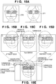
- FIG. 15A shows example feature amounts obtained as a result of the learning used in such processing.
- a feature amount 210 exhibits the feature that, when a small rectangular portion around the eyes is compared with a portion beneath the eyes (cheek portion), the portion around the eyes is darker than the portion beneath the eyes.
- a feature amount 211 exhibits the feature that, in the portion around the eyes, the portion of each eye is dark and the glabellar portion between the eyebrows is lighter than the portion of each eye.
- Input data are compared to such results of learning (learnt feature amounts), and if True is output for all of the feature amount identification processes, it is determined that the input data indicate a (human) face.
- identification processing is sectioned into sections (hereinafter referred to as stages), True/False identification is performed for each stage, and thereby identification of face or non-face is performed.
- earlier stages use only a simple feature so that the probability of a false negative (determination of a face as non-face, or an oversight) is minimized and the probability of a false positive (determination of a non-face as face, or an erroneous detection) is relatively high.
- Using only simple features enables identification processing with a reduced number of computations, and thus high-speed processing is possible even when the processing is performed using processors.
- a rectangular region is clipped from the entire image to identify the clipped region. According to the above-described method, more rectangular regions can be efficiently identified as False (non-face) in earlier stages, and thus the face detection processing over the entire image can be completed in a short time.
- Band_a is a band whose top corner is the pixel at a position shifted in the sub-scanning direction (vertical direction) by one pixel from the top corner of Band_A.
- this scanning method first, the pixel on the upper left of the input image is set as a starting point, and identification processing is performed on a rectangular region (subwindow) in which the upper left pixel of the rectangular region coincides with the starting point. Next, the identification processing is performed sequentially on rectangular regions at positions each shifted by one pixel in the main scanning direction until the right edge of a rectangular region coincides with the right edge of the input image. The processing on Band_A is completed at this time.
- the pixel at a position shifted by one pixel in the sub-scanning direction from the starting point used when Band_A was processed is set as a starting point, and the identification processing is performed sequentially on rectangular regions at positions each shifted by one pixel in the main scanning direction until the right edge of a rectangular region coincides with the right edge of the input image.
- the processing on Band_a is completed at this time. After that, the processing is performed on each band with a shift by one pixel in the sub-scanning direction until the lower edge of a rectangular region coincides with the lower edge of the input image.
- FIGS. 15A to 15E are diagrams showing relative positions between the feature amount 210 and a face portion when, with respect to a face portion of the input image, rectangular regions are scanned in the main scanning direction. At a rectangular region position shown in FIG.
- FIGS. 15B and 15D respectively show left and right edge rectangular regions that are determined to be True (likely to be a face) as a result of comparison against the feature amount 210.
- a rectangular region at the position shifted by one pixel to the left from FIG. 15B is determined as False (non-face) and a rectangular region at the position shifted by one pixel to the right from FIG. 15D is also determined as False (non-face) as a result of identification.
- FIG. 15E shows the transition of the identification result from False to True and then from True to False as scanning proceeds in FIG. 15A to FIG. 15D .
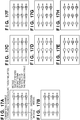
- FIG. 16A shows an example in which there is only one face portion within one band.
- Nine Ts (True) are in succession and thereafter 27 Fs (False) are in succession with the progress of scanning.
- FIG. 16B shows an example in which two face portions are spaced apart from each other within the same band.
- Nine Ts (True) are followed by 6 Fs (False), and further 9 Ts (True) are followed by 6 Fs (False).
- FIG. 16C shows an example in which two face portions are adjacent to each other within the same band.
- Nine Ts (True) are followed by one F (False)
- further 9 Ts (True) are followed by one F (False).
- the identification processing is sectioned into stages, and True or False is determined for each stage.
- the probability of occurrence of True in each stage is referred to as "passage rate".
- the passage rate of the stage 0 is calculated from the ratio between T (True) and F (False) to be 1/4.
- the passage rate is 3/5 in the case of FIG. 16B
- the passage rate is 9/10 in the case of FIG. 16C .
- the total number of processes (the number of input rectangular regions) of the first or leading stage of the identification processing is defined as S. Only the rectangular regions identified as True in the first stage of the identification processing, which is the preceding stage, are input to the next second stage of the identification processing. Accordingly, the data amount, or in other words, the number of rectangular regions, processed by the second stage of the identification processing will be the product (S ⁇ p[1]) obtained by multiplying the number of rectangular regions processed by the first stage of the identification processing by the passage rate p[1] of the first stage of the identification processing.
- the data amount, or in other words, the number of rectangular regions, processed by the third stage of the identification processing amounts to the product, (S ⁇ p[1]) ⁇ p[2], obtained by multiplying the number of rectangular regions processed by the second stage of the identification processing by the passage rate p[2] of the second stage of the identification processing.
- the data amount, or in other words, the number of rectangular regions, processed by the Nth stage of the identification processing can be represented as follows: S * p 0 * p 1 * ⁇ * p N ⁇ 2 * p N ⁇ 1 .
- the passage rate varies depending on the type of input image and the processing position within the image (the position of a rectangular region to be processed).
- the passage rate of an image having a high face density such as a group photograph generally is higher than the passage rate of an image having a low face density such as a landscape photograph.
- the face density is higher in the lower portion of the photograph. Accordingly, the passage rate during identification processing on the lower portion (people portion) of the photograph having a high face density is generally higher than the passage rate during identification processing on the upper portion (landscape portion) of the photograph having a low face density.
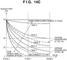
- FIG. 14A is an example of a group photograph including a relatively large number of face portions in the input image.
- the average accumulated passage rate at each stage is plotted in a graph shown in FIG. 14C for Band_A, Band_B, Band_C and Band_D shown in FIG. 14A .
- bands having a low face density such as Band_A
- almost all of the rectangular regions are determined as non-face by the identification processing of the stage 0, and thus the average accumulated passage rate in the stage 1 is substantially 0%.
- FIG. 14B is an example of a group photograph including a smaller number of face portions in the input image than the group photograph of FIG. 14A .
- the average accumulated passage rate at each stage is also plotted for Band_X, Band_Y and Band_Z shown in FIG. 14B .
- the average accumulated passage rate in Band_X is similar to that of Band_A of FIG. 14A , but in Band_Z having the highest face density in FIG. 14B , the average accumulated passage rate at the stage 2 is below 50%.
- the average accumulated passage rate varies significantly even at the same processing position.
- the identification processing as typified by the Viola & Jones method is implemented by the multistage cascade processing composed of a plurality of stages, and by determining more rectangular regions as non-face in earlier stages, high-speed processing is achieved.
- the probability that non-face is determined in each stage varies significantly depending on the type of input image and the processing position within the input image.
- the longest of the processing times of the stages rate-limits the overall processing time. Accordingly, provided that, in all of the stages, the passage rate is 100% and the processing times are uniform, the processing speed can be increased by an amount corresponding to the number of stages (by 4 times if there are 3 stages).
- Spatially parallel processing is a speed-up technique in which, in order to further speed up the above-mentioned pipeline processing, a plurality of pipelines are mounted to simultaneously process a plurality of input data pieces.
- the processing speed can be increased by the amount of spatial parallelization (by 4 times if 4 pipelines are mounted). Accordingly, with a configuration in which 4 pipelines, each having 3 stages, are mounted using 12 discriminators, theoretically, the processing speed can be increased by 12 times.
- the temporally parallel processing and the spatially parallel processing are combined to achieve a performance improvement.
- the conventional technology tries to, by mounting 12 discriminators, improve performance by an amount corresponding to the number of pipeline stages ⁇ the degree of spatial parallelism (12 times in the above example) compared to the configuration in which one discriminator is mounted.
- the average accumulated passage rate varies greatly depending on the type of input image and the processing position within the input image.
- the face density is high, it is possible to improve the performance by an amount close to the amount corresponding to the number of pipeline stages ⁇ the degree of spatial parallelism, but when the face density is low, the performance improvement does not come close to the amount corresponding to the number of pipeline stages ⁇ the degree of spatial parallelism.
- the speed-up technique using temporally/spatially parallel processing according to the conventional technology is problematic in that sufficient performance improvement cannot be achieved depending on the passage rate, and also in that the performance varies significantly depending on the type of input image and the processing position within the input image.
- FIGS. 17A to 17H are schematic diagrams showing the average operation state of the discriminators when the identification processing is performed on Band_A, Band_B, Band_C, Band_D, Band_X, Band_Y and Band_Z. It should be noted that the following description assumes that the processing time is the same in all of the discriminators.
- the identification processing of desciminators for each stage are defined by feature amount used for the identification. Therefore, if feature amounts and connection relationship among the descriminators can be changed, assignment of descriminators to each stage can be adjusted to disperse loads.
- various dynamic load balancing methods have been proposed in order to improve and stabilize the processing performance by making the operation ratios of the processors uniform.
- Document 2 Japanese Patent Laid-Open No. 2003-256221 (hereinafter referred to as Document 2) presents the following proposal. Specifically, processes generated by parallel programs are assigned to processing timeslots of a plurality of processors according to the time corresponding to the processor distribution ratio preset for each parallel program.
- the data processing controlling a plurality of processes, in which whether or not to execute the next processing is determined based on a processing result, such as the face detection according to the Viola & Jones method, is disadvantageous in that, when the load (execution time) of processing (process) varies depending on the input data, the effect of suppressing the performance degradation and the performance variation is small.
- a data processing apparatus and a data processing method are provided that have little performance variation depending on the type of input image and the processing position within an image, as well as uniform and high processing performance.
- the present invention in its first aspect provides a data processing apparatus as specified in claims 1 to 11.
- the present invention in its second aspect provides a data processing method as specified in claim 12.
- FIG. 1 is a block diagram showing an example of an overall configuration of a data processing apparatus according to an embodiment of the present invention.
- the data processing apparatus executes data processing composed of a predetermined number of two or more stages by using a plurality of processing modules.
- the processing modules are assigned to these stages. Partial data (e.g. data pieces or portions) sequentially extracted from input data is processed, and whether or not to process the partial data in a subsequent stage is determined according to the processing result of a preceding stage.
- image data is used as the input data
- discriminators for performing pattern identification using the image data are used as processing modules, but the input data and the processing modules are not limited thereto.
- Application to, for example, pattern recognition regarding DNA base sequence information or pattern recognition regarding audio signals is also possible.
- a CPU 100 performs overall control of the data processing apparatus by executing various programs stored in a ROM 101, which is a read-only memory.
- a DRAM 103 stores image data to be processed. The image data stored in the DRAM 103 is supplied to a controller 105 via a DRAM controller 102.
- a processing unit 106 includes 12 discriminators 0 to 11 for performing pattern identification.
- a module configuration changing unit 110 distributes the discriminators 0 to 11 to a predetermined number of stages, respectively, and connects the discriminators such that a plurality of partial data pieces are processed in parallel over a predetermined number of stages and within at least one stage, details of which will be described later with reference to FIGS. 2 and 3 .
- the CPU 100 acquires setting data as typified by, for example, feature amounts (e.g. image condition) from a processing setting data storing unit 104 included in the ROM 101, and sets the data in the discriminators inside the processing unit 106. More specifically, in each discriminator (for example a dedicated circuit or device), a feature amount corresponding to the stage to which the discriminator belongs is set (for example, the feature amount 210 shown in FIG. 15A is set in the discriminators belonging to the stage 0, and the feature amount 211 is set in the discriminators belonging to the stage 1).
- feature amounts e.g. image condition
- the CPU 100 acquires setting data as typified by, for example, image data positions (addresses) from the processing setting data storing unit 104, and sets the data in the controller 105. Furthermore, in this initial state, the CPU 100 initializes the module configuration changing unit 110.
- the module configuration changing unit 110 sets connections of the discriminators 0 to 11 in the initial state such that 4 pipeline configurations, each having 3 stages, are connected in parallel, which will be described later with reference to FIGS. 2 and 3 .
- the CPU 100 sends a notification to start processing to the controller 105 and the processing unit 106.
- the controller 105 sequentially reads rectangular region data from the image data stored in the DRAM 103 by accessing the DRAM controller 102 based on the set image data positions (addresses), and transfers the data to the processing unit 106.
- the rectangular regions have been described above with reference to FIG. 14A .
- the processing unit 106 sequentially executes identification processing on the rectangular region image data that has been transferred.
- the processing results are stored in a result storing unit 112.
- the CPU 100 can obtain coordinate values of the rectangular regions determined to be a face in the image data by reading the results.
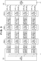
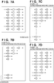
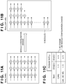
- FIG. 3 is a diagram showing a connection pattern (initial state) of the discriminators in the case where the discriminators 0 to 11 are connected by the module configuration changing unit 110 such that 4 pipeline configurations, each having 3 stages, are connected in parallel.
- the connections of the discriminators can be changed as shown in FIG. 2 by the module configuration changing unit 110 switching the connections.
- the discriminator 0 is connected to the controller 105, and the discriminator 0, the discriminator 1, and the discriminator 2 are connected in the stated order, and thereafter the output of the discriminator 2 is supplied to the result storing unit 112.
- a valid signal as used herein refers to a control signal for controlling whether data_in is valid.
- the input data is output to data_in of the next discriminator 1, and "1" indicating that the input data is valid is output to valid_in of the discriminator 1, whereby the discriminator 1 can detect and process valid input data.
- the discriminators are connected so as to perform spatially parallel processing.
- 4 pipeline configurations each executing processing over the 3 stages, are connected in parallel with the aim of achieving a processing speed 12 times faster in total.
- coordinate data (coord_in) that indicates the coordinate position of a rectangular region is used in order to determine to which coordinates of rectangular region a processing result belongs so as to perform spatially parallel processing.
- coord_out0, coord_out1, coord_out2, and coord_out3 are input to the result storing unit 112 from the 4 discriminators 2, 5, 8 and 11 mounted for the stage 2.
- the number of discriminators mounted for the stage 0 is quadrupled, and it is therefore possible to simultaneously process 4 different rectangular region data pieces (data_in0, data_in1, data_in2, and data_in3). Accordingly, in the case where 12 discriminators can be operated in parallel completely simultaneously, the processing speed can be increased by up to 12 times compared to the configuration including one discriminator.
- each of the signal lines is a representation of 3 types of input/output signals (coordinate data (coord_in/out), image data (data_in/out) and control signal (valid_in/out)) shown in FIG. 1 bundled into a single line.
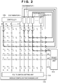
- the data processing apparatus of the present embodiment further includes a passage rate detecting unit 107, a processing time storing unit 108 and a calculating unit 109. Also, the connections between discriminators are changed via (by) the module configuration changing unit 110 depending on the results of calculation by the calculating unit 109.
- the passage rate detecting unit 107 detects (determines) the passage rate (the ratio of the processing result that causes the subsequent stage to execute processing) of each stage upon receiving an input of the identification result signal (result signal, the same as the valid lines in the present embodiment) that is output from each discriminator.
- the calculating unit 109 (calculation program executed by the CPU 100) calculates a module configuration by using the passage rate of each stage (discriminators) detected by the passage rate detecting unit 107 and the discriminator processing time of each stage stored in the processing time storing unit 108.
- the module configuration changing unit 110 changes the module configuration based on the configuration information calculated by the calculating unit 109.
- the module configuration changing unit 110 is composed of a crossbar switch such that all of the connections of the input signals (in0 to in11) from the controller 105, the output signals (out0 to out11) to the result storing unit and the input/output signals of the discriminators 0 to 11 can be set. Connections between input and output are established by connecting (ON) at most one switch from among a plurality of horizontally disposed switches. The opening and closing (ON/OFF) of the switches are controlled by a route (switch) setting unit 114 (see figure 2 ).
- Td N Tm N * P N
- the stages have a uniform processing time.
- Num[N] such that T[N] is uniform in all of the stages, it is possible to calculate the optimal number of discriminators that should be mounted for each stage.
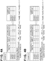
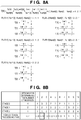
- a description will be given of a method for calculating the optimal number of discriminators that should be mounted for the stage 0, 1 or 2 (Num[0], Num[1] or Num[2]) based on the processing time Tm per discriminator and information regarding the accumulated passage rate P in each stage shown in Example 1 of FIG. 4A , performed by the calculating unit 109.
- the number of discriminators distributed for each stage is determined from the processing time of each stage and the data amount processed in each stage that is determined using the accumulated passage rate, such that the processing time is uniform over the stages.
- each stage such that the number of discriminators (processing modules) for each stage satisfies the ratio of Equation (4) by using the passage rate detected by the passage rate detecting unit 107, it is possible to achieve an optimal circuit configuration in which the number of modules that are shut down is small.
- Examples 2, 3 and 4 also show examples in which the ratio of the number of modules among the stages is calculated in the same manner.
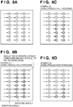
- FIGS. 6A to 6D show a conventional example in which the module configuration is not changed.
- FIGS. 7A to 7D show an example of the present embodiment in which the module configuration is changed.
- FIGS. 6A and 7A show simplified diagrams showing the initial state of the module configuration. In the initial state, 8 discriminators are mounted for each of 3 stages, with a degree of temporal parallelism of 3 and a degree of spatial parallelism of 8. The total number of discriminators is 24. This aims to improve the performance by up to 24 times relative to the configuration including one discriminator.
- the calculating unit 109 instructs the module configuration changing unit 110 to satisfy the ratio of the number of modules calculated in this manner.
- all of the discriminators are constantly operated, and thus the performance can be improved by 24 times that of the configuration including one discriminator.
- the data supply to the subsequent stage is interrupted, causing a situation in which the discriminators mounted for the subsequent stage are not operated, and causing performance degradation.
- the average accumulated passage rate varies, the number of non-operational discriminators varies, causing performance variation.
- the present embodiment even when the average accumulated passage rate decreases or varies, the number of non-operational discriminators can be always minimized, and thus a high level of performance that is constantly stable can be acquired.
- the ratio of the number of modules is an integer ratio.
- the ratio of the number of modules will not always be an integer ratio. Even if the ratio is an integer ratio, there are cases where it is not possible to change the configuration to satisfy the calculated ratio depending on the total number of mounted modules and the like. For example, in Example 1 shown in FIG. 4A , if the total number of mounted modules is 6, the module configuration that satisfies the ratio: 4:2:1 cannot be satisfied.
- the ratio of the number of modules is determined in the following procedure.
- options to mount at least one discriminator for all of the stages are determined e.g. by selection from among all of the options of how the discriminators could be arranged. This is an appropriate selection criterion because if there is a stage for which no discriminator is mounted, the entire processing will not be complete. Then, in order to determine the best configuration from among the options selected in the first procedure, the following second procedure is applied.
- the processing time T[N] per input data piece (rectangular image data piece) in the stage N is determined for all of the stages using Equation (2), and the highest value thereof is set as a first processing time of the option.
- the highest value for the stage processing time (first processing time) is set as the overall processing time.
- an option having the smallest value for the first processing time is selected from among all of the options selected in the first procedure, and this is set as the best configuration. If a plurality of options are selected in the second procedure (so if a plurality of configurations have the smallest value for the first processing time), a third procedure is further applied.
- the processing time T[N] per input data piece (rectangular image data piece) in the stage N is determined for all of the stages using Equation (2), and the second highest value thereof is set as a second processing time of the option. Then, an option having the smallest value for the second processing time is selected from among all of the options selected in the second procedure, and this is set as the best configuration.
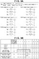
- FIGS. 8A and 8B show an example in which the above procedures are applied to Example 1 of FIG. 4A .
- FIG. 8B shows options 1 to 10 to mount at least one discriminator for all of the stages.
- the best configuration is determined from among the options selected in the first procedure. For this reason, as described above, with respect to an option, the processing time T[N] per input data piece (rectangular image data piece) in the stage N is determined for all of the stages using Equation (2), and the highest value is set as a first processing time of the option.
- FIG. 8A shows calculations for the configurations of the first to fifth options shown in FIG. 8B .
- An option that has the smallest value for the first processing time is selected from among all of the options selected in the first procedure, and this is set as the best configuration.
- the second option having a smaller value (1/3) for the highest stage processing time than the other options is selected as the best configuration.
- FIGS. 9A and 9B taking the same example as in FIGS. 8A and 8B in which 6 discriminators are mounted using the conditions shown in Example 3 shown in FIG. 4C .
- options 1 to 10 to mount at least one discriminator for all of the stages are shown in FIG. 9B.
- FIG. 9A shows calculations for the configurations of the first to sixth options shown in FIG. 9B .
- the module configulation is changed such that the processing time is uniform over the stages. Also, the module configuration is changed such that the processing time of a stage whose processing time is the longest is shortened. Thus, entire processing time can be reduced.
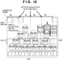
- a procedure for detecting the passage rate performed by the passage rate detecting unit 107 when the input image is sequentially processed will be described next with reference to FIG. 10 and FIGS. 11A to 11C .
- an image scanning method the method described earlier is used in which identification processing is performed pixel by pixel in the main scanning direction of the input image.
- the passage rate detecting unit 107 sets the passage rate to a default value (for example, 100%), and sets the module configuration to a default configuration shown in FIG. 11A .
- the passage rate detecting unit 107 updates the passage rates of the stages based on the identification results of the stages input on a pixel-by-pixel basis.
- the calculating unit 109 calculates and determines a configuration used to process the next and subsequent pixels in the above-described procedures, based on the passage rates of the stages at that time.
- the calculating unit 109 calculates the passage rates at that time.
- An update section is defined by a predetermined number of pixels in the main scanning direction and the width of a band in the sub-scanning direction (so corresponds to the area of the input image covered by a predetermined number of rectangular region data pieces extracted sequentially from the input image). Then, the calculating unit 109 instructs the module configuration changing unit 110 to change the configuration based on the calculated values.
- the passage rate detecting unit 107 resets the passage rates to the above-described default value.
- FIG. 10 shows the average passage rates of the stages 0 and 1 for the W0 section and the W1 section when Band_C of the input image shown in FIG. 10 is processed.
- the passage rates shown by the passage rate detecting unit 107 are set to a default value. Accordingly, the configuration when the W0 section (Band_C(W0)) of Band_C is processed is the default configuration shown in FIG. 11A .
- the configuration is not changed.
- a configuration calculation and a configuration change are performed each time the right-edge pixel of each section has been processed, and thereby the sections W1 and W2 are sequentially processed.
- FIG. 2 shows an example in which the following connections are implemented by the module configuration changing unit 110: the input signal (in0) of the controller 105 ⁇ the discriminator 0 ⁇ the discriminator 1 ⁇ the discriminator 2 ⁇ the output signal (out0) to the result storing unit 112. As shown in FIG. 2 , this route can be implemented by the switches at the connecting portions being connected (ON) .
- the discriminators 8 and 9 are required to be connected to either the discriminator 10, 11 of the next stage, and the discriminators 4 and 5 are required to be connected to either the discriminator 6, 7, 8, 9 of the next stage, but they are unconnected in the initial route settings.
- the route (switch) setting unit 114 monitors the control signals (valid) output from the discriminators.
- the route (switch) setting unit 114 detects that the valid signal of the discriminator 8 has been enabled, then, the route (switch) setting unit 114 waits for either the discriminator 6 or 7 that finishes data transfer (the valid signals being disabled) earlier (so the setting unit waits for whichever of discriminator 6 or 7 finishes data processing first). If the discriminator 6 finishes data transfer earlier than the discriminator 7, the connection route is changed as follows immediately after the discriminator 6 has finished transferring data:
- the identification result output by each of the discriminators 0 to 11 is input to the passage rate detecting unit 107.
- the discriminators are connected to a network (interconnect) 80. While identification processing is being executed on given rectangular image data, a status indicating "under processing" (for example, an assertion of a busy signal) is transmitted to the network 80.
- a communication route setting unit 111 mounted on the network 80 determines to which discriminator the processing result of which discriminator is transmitted, or in other words, a connection relationship between discriminators (topology).
- the outputs of the discriminators 0 to 2 sharing the processing of the stage 0 are set so as to be transmitted to the discriminators 3 to 5 sharing the processing of the stage 1.
- the outputs of the discriminators 3 to 5 are set so as to be transmitted to the discriminators 6 to 8 sharing the processing of the stage 2.
- the content of the settings in the communication route setting unit 111 is determined based on the module configuration calculated by the calculating unit 109.
- the content of the settings in the communication route setting unit 111 can be changed such that the outputs of the discriminators 0 to 2, 5, 7 and 8 are transmitted to the discriminators 3 and 4, and the outputs of the discriminators 3 and 4 are transmitted to the discriminator 6.
- a configuration shown in FIG. 12B is implemented.
- the network 80 selects one from among the plurality of discriminators, which has not transmitted a status indicating "under processing" (not asserted a busy signal), and performs control so as to establish a connection. However, if all of the transmission destinations are involved in processing, the network 80 waits until at least one of them finishes processing, and then establishes a connection.
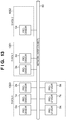
- FIG. 13 is a diagram in which the discriminators of FIG. 12B are implemented with processors.
- the identification module configuration change from FIG. 12A to FIG. 12B can be achieved simply by changing programs executed by the processors. Specifically, the configuration can be changed by:
- the number of stages in the cascade can be as high as several tens of stages, and thus it may be difficult to mount at least one dedicated discriminator for each stage in terms of circuitry scale. In such a case, it is necessary to optimize the circuitry scale by, for example, integrating a plurality of consecutive stages and mounting a discriminator for an integrated stage.
- integration of at least two consecutive stage processes and execution of the integrated stage by one processor can be achieved easily by changing programs.
- the total number of discriminators was a given number.
- processors in the case where there are a large number of stages, it is possible to easily perform integration of stage processes executed by a single processor. Accordingly, wider selection of configurations can be provided for the given total number of processors, whereby an even better module configuration can be determined.
- passage rates for all stages are acquired to change module configuration.
- the present invention is not limited to this.
- the calculation of the passage rate and the change of the module configuration may be perfomed for a subset of stage(s) whose degree of passage rate variability is (relatively) large. This arrangement is expected to enhance the effects of the invention on the whole.
- the module configuration (the degree of spatial parallelism of each stage, or in other words, the number of discriminators that should be mounted for each stage) is dynamically changed based on the passage rate detected for each stage processing and the processing time of each stage. Accordingly, the present invention has the effect that there is little performance variation depending on the type of input image or the processing position within an image, and a uniform and high level of processing performance can be acquired.
- aspects of the present invention can also be realized by a computer of a system or apparatus (or devices such as a CPU or MPU) that reads out and executes a program recorded on a memory device to perform the functions of the above-described embodiment(s), and by a method, the steps of which are performed by a computer of a system or apparatus by, for example, reading out and executing a program recorded on a memory device to perform the functions of the above-described embodiment(s).
- the program is provided to the computer for example via a network or from a recording medium of various types serving as the memory device (e.g., computer-readable storage medium).
- the present invention also provides a data processing apparatus for using a plurality of processing modules to sequentially execute data processing on a plurality of partial data of input data through a plurality of stages, wherein, in the data processing, it is determined, depending on a processing result in a preceding stage on data, whether or not to execute processing on the data in a subsequent stage, the apparatus comprising:
Landscapes
- Engineering & Computer Science (AREA)
- Software Systems (AREA)
- Theoretical Computer Science (AREA)
- Physics & Mathematics (AREA)
- General Engineering & Computer Science (AREA)
- General Physics & Mathematics (AREA)
- Image Processing (AREA)
- Multi Processors (AREA)
- Image Analysis (AREA)
Applications Claiming Priority (1)
| Application Number | Priority Date | Filing Date | Title |
|---|---|---|---|
| JP2010112661A JP5574816B2 (ja) | 2010-05-14 | 2010-05-14 | データ処理装置及びデータ処理方法 |
Publications (3)
| Publication Number | Publication Date |
|---|---|
| EP2386950A2 EP2386950A2 (en) | 2011-11-16 |
| EP2386950A3 EP2386950A3 (en) | 2013-07-24 |
| EP2386950B1 true EP2386950B1 (en) | 2020-11-25 |
Family
ID=44357938
Family Applications (1)
| Application Number | Title | Priority Date | Filing Date |
|---|---|---|---|
| EP11165810.0A Not-in-force EP2386950B1 (en) | 2010-05-14 | 2011-05-12 | Data processing apparatus and data processing method |
Country Status (4)
| Country | Link |
|---|---|
| US (1) | US9003167B2 (OSRAM) |
| EP (1) | EP2386950B1 (OSRAM) |
| JP (1) | JP5574816B2 (OSRAM) |
| CN (1) | CN102243600B (OSRAM) |
Families Citing this family (3)
| Publication number | Priority date | Publication date | Assignee | Title |
|---|---|---|---|---|
| JP5618670B2 (ja) | 2010-07-21 | 2014-11-05 | キヤノン株式会社 | データ処理装置及びその制御方法 |
| JP7563468B2 (ja) * | 2020-10-02 | 2024-10-08 | 日本電気株式会社 | 画像処理装置、画像処理方法及びプログラム |
| JP7697480B2 (ja) * | 2023-01-04 | 2025-06-24 | トヨタ自動車株式会社 | リソース管理装置、リソース管理方法及びリソース管理用コンピュータプログラム |
Family Cites Families (35)
| Publication number | Priority date | Publication date | Assignee | Title |
|---|---|---|---|---|
| JPS51112236A (en) | 1975-03-28 | 1976-10-04 | Hitachi Ltd | Shape position recognizer unit |
| JPH0262671A (ja) | 1988-08-30 | 1990-03-02 | Toshiba Corp | カラー編集処理装置 |
| KR100319768B1 (ko) * | 1991-08-13 | 2002-04-22 | 마거리트 와그너-달 | 영상화및그래픽처리시스템내에서의다차원주소발생방법 |
| US5668631A (en) | 1993-12-20 | 1997-09-16 | Minolta Co., Ltd. | Measuring system with improved method of reading image data of an object |
| US6407817B1 (en) | 1993-12-20 | 2002-06-18 | Minolta Co., Ltd. | Measuring system with improved method of reading image data of an object |
| US6545687B2 (en) | 1997-01-09 | 2003-04-08 | Canon Kabushiki Kaisha | Thumbnail manipulation using fast and aspect ratio zooming, compressing and scaling |
| US6643400B1 (en) | 1999-03-31 | 2003-11-04 | Minolta Co., Ltd. | Image processing apparatus and method for recognizing specific pattern and recording medium having image processing program recorded thereon |
| US20030228565A1 (en) | 2000-04-26 | 2003-12-11 | Cytokinetics, Inc. | Method and apparatus for predictive cellular bioinformatics |
| US7092569B1 (en) | 1999-07-29 | 2006-08-15 | Fuji Photo Film Co., Ltd. | Method and device for extracting specified image subjects |
| US6993641B2 (en) * | 2000-11-08 | 2006-01-31 | Pts Corporation | Stall control |
| EP1339100A1 (en) | 2000-12-01 | 2003-08-27 | Ebara Corporation | Inspection method and apparatus using electron beam, and device production method using it |
| EP1324528A1 (en) * | 2001-12-31 | 2003-07-02 | TELEFONAKTIEBOLAGET LM ERICSSON (publ) | Apparatus and method for flexible data rate matching |
| JP2003256221A (ja) | 2002-02-28 | 2003-09-10 | Fujitsu Ltd | 並列プロセス実行方法、及びマルチプロセッサ型コンピュータ |
| US7181085B1 (en) * | 2002-04-04 | 2007-02-20 | Acorn Technologies, Inc. | Adaptive multistage wiener filter |
| US20030226000A1 (en) * | 2002-05-30 | 2003-12-04 | Mike Rhoades | Collapsible pipeline structure and method used in a microprocessor |
| US7444632B2 (en) * | 2003-09-25 | 2008-10-28 | International Business Machines Corporation | Balancing computational load across a plurality of processors |
| WO2006036027A1 (ja) | 2004-09-30 | 2006-04-06 | Fujifilm Corporation | 画像処理装置および方法、ならびに画像処理プログラム |
| US20060200651A1 (en) * | 2005-03-03 | 2006-09-07 | Collopy Thomas K | Method and apparatus for power reduction utilizing heterogeneously-multi-pipelined processor |
| US20060224864A1 (en) * | 2005-03-31 | 2006-10-05 | Dement Jonathan J | System and method for handling multi-cycle non-pipelined instruction sequencing |
| JP4231516B2 (ja) * | 2006-08-04 | 2009-03-04 | 株式会社日立製作所 | 実行コードの生成方法及びプログラム |
| WO2008117468A1 (ja) * | 2007-03-27 | 2008-10-02 | Advantest Corporation | 試験装置 |
| US8103108B2 (en) | 2007-05-01 | 2012-01-24 | Sharp Kabushiki Kaisha | Image processing apparatus, image forming apparatus, image processing system, and image processing method |
| JP5058681B2 (ja) * | 2007-05-31 | 2012-10-24 | キヤノン株式会社 | 情報処理方法及び装置、プログラム、記憶媒体 |
| CN101334780A (zh) | 2007-06-25 | 2008-12-31 | 英特维数位科技股份有限公司 | 人物影像的搜寻方法、系统及存储影像元数据的记录媒体 |
| US8284205B2 (en) * | 2007-10-24 | 2012-10-09 | Apple Inc. | Methods and apparatuses for load balancing between multiple processing units |
| JP5101993B2 (ja) | 2007-11-01 | 2012-12-19 | キヤノン株式会社 | 情報処理装置および情報処理方法 |
| US20090125706A1 (en) * | 2007-11-08 | 2009-05-14 | Hoover Russell D | Software Pipelining on a Network on Chip |
| JP4948379B2 (ja) * | 2007-12-18 | 2012-06-06 | キヤノン株式会社 | パターン識別器生成方法、情報処理装置、プログラム及び記憶媒体 |
| US20090208112A1 (en) | 2008-02-20 | 2009-08-20 | Kabushiki Kaisha Toshiba | Pattern recognition method, and storage medium which stores pattern recognition program |
| JP4513898B2 (ja) * | 2008-06-09 | 2010-07-28 | 株式会社デンソー | 画像識別装置 |
| JP5100596B2 (ja) * | 2008-10-03 | 2012-12-19 | キヤノン株式会社 | 情報処理装置及び情報処理方法 |
| JP5258506B2 (ja) | 2008-10-24 | 2013-08-07 | キヤノン株式会社 | 情報処理装置 |
| CN101515286B (zh) * | 2009-04-03 | 2012-04-11 | 东南大学 | 基于图像特征多级过滤的图像匹配方法 |
| JP2011076495A (ja) * | 2009-09-30 | 2011-04-14 | Toshiba Corp | マルチプロセッサによる並列処理装置 |
| JP5618670B2 (ja) | 2010-07-21 | 2014-11-05 | キヤノン株式会社 | データ処理装置及びその制御方法 |
-
2010
- 2010-05-14 JP JP2010112661A patent/JP5574816B2/ja not_active Expired - Fee Related
-
2011
- 2011-05-06 US US13/102,168 patent/US9003167B2/en not_active Expired - Fee Related
- 2011-05-12 EP EP11165810.0A patent/EP2386950B1/en not_active Not-in-force
- 2011-05-16 CN CN2011101259221A patent/CN102243600B/zh not_active Expired - Fee Related
Non-Patent Citations (1)
| Title |
|---|
| None * |
Also Published As
| Publication number | Publication date |
|---|---|
| JP2011242898A (ja) | 2011-12-01 |
| CN102243600A (zh) | 2011-11-16 |
| JP5574816B2 (ja) | 2014-08-20 |
| US20110283088A1 (en) | 2011-11-17 |
| US9003167B2 (en) | 2015-04-07 |
| CN102243600B (zh) | 2013-01-23 |
| EP2386950A2 (en) | 2011-11-16 |
| EP2386950A3 (en) | 2013-07-24 |
Similar Documents
| Publication | Publication Date | Title |
|---|---|---|
| US8891877B2 (en) | Data processing apparatus and control method thereof | |
| EP2386950B1 (en) | Data processing apparatus and data processing method | |
| CN106233719B (zh) | 图像处理设备和方法以及外科手术系统 | |
| US11747278B2 (en) | Deposit detection device for detecting a partial covering location, a not-adhere location, and a diffuse reflection location | |
| JP5100596B2 (ja) | 情報処理装置及び情報処理方法 | |
| CN116389831B (zh) | 一种基于云原生的离线渲染系统及方法 | |
| CN116188808B (zh) | 图像特征提取方法和系统、存储介质及电子设备 | |
| US11696038B2 (en) | Multiple camera color balancing | |
| US8666176B2 (en) | Object recognition apparatus and object recognition method | |
| CN118138801B (zh) | 视频数据处理方法、装置、电子设备及存储介质 | |
| JP5258506B2 (ja) | 情報処理装置 | |
| CN113892081B (zh) | 用于积分图像计算的硬件加速器 | |
| EP4198869A1 (en) | Electronic apparatus, and image processing method for electronic apparatus | |
| CN116091321A (zh) | 图像缩放方法、装置、设备及存储介质 | |
| US11048922B2 (en) | Gesture detection using color segmentation | |
| CN113419842B (zh) | 一种基于JavaScript构建边缘计算微服务的方法、装置 | |
| CN114390266B (zh) | 一种图像白平衡处理方法、设备及计算机可读存储介质 | |
| US11800258B2 (en) | High-performance CNN inference model at the pixel-parallel CMOS image sensor | |
| JP2004173060A (ja) | ノイズ除去方法、撮像装置およびノイズ除去プログラム | |
| EP3680827A1 (en) | Information processing apparatus and memory control method | |
| CN113642442A (zh) | 人脸检测方法及装置、计算机可读存储介质、终端 | |
| CN111563579B (zh) | 基于数据流的cnn加速方法、装置、设备及存储介质 | |
| CN118195957A (zh) | Yuv数据处理方法和装置、数据处理设备、芯片及存储介质 | |
| CN115934293A (zh) | 一种指令派发方法、装置、芯片及电子设备 | |
| CN117750229A (zh) | 图像去坏点的方法及装置、电子设备 |
Legal Events
| Date | Code | Title | Description |
|---|---|---|---|
| AK | Designated contracting states |
Kind code of ref document: A2 Designated state(s): AL AT BE BG CH CY CZ DE DK EE ES FI FR GB GR HR HU IE IS IT LI LT LU LV MC MK MT NL NO PL PT RO RS SE SI SK SM TR |
|
| AX | Request for extension of the european patent |
Extension state: BA ME |
|
| PUAI | Public reference made under article 153(3) epc to a published international application that has entered the european phase |
Free format text: ORIGINAL CODE: 0009012 |
|
| PUAL | Search report despatched |
Free format text: ORIGINAL CODE: 0009013 |
|
| AK | Designated contracting states |
Kind code of ref document: A3 Designated state(s): AL AT BE BG CH CY CZ DE DK EE ES FI FR GB GR HR HU IE IS IT LI LT LU LV MC MK MT NL NO PL PT RO RS SE SI SK SM TR |
|
| AX | Request for extension of the european patent |
Extension state: BA ME |
|
| RIC1 | Information provided on ipc code assigned before grant |
Ipc: G06F 9/50 20060101AFI20130614BHEP |
|
| 17P | Request for examination filed |
Effective date: 20140124 |
|
| RBV | Designated contracting states (corrected) |
Designated state(s): AL AT BE BG CH CY CZ DE DK EE ES FI FR GB GR HR HU IE IS IT LI LT LU LV MC MK MT NL NO PL PT RO RS SE SI SK SM TR |
|
| STAA | Information on the status of an ep patent application or granted ep patent |
Free format text: STATUS: EXAMINATION IS IN PROGRESS |
|
| 17Q | First examination report despatched |
Effective date: 20180131 |
|
| GRAP | Despatch of communication of intention to grant a patent |
Free format text: ORIGINAL CODE: EPIDOSNIGR1 |
|
| STAA | Information on the status of an ep patent application or granted ep patent |
Free format text: STATUS: GRANT OF PATENT IS INTENDED |
|
| INTG | Intention to grant announced |
Effective date: 20200619 |
|
| GRAS | Grant fee paid |
Free format text: ORIGINAL CODE: EPIDOSNIGR3 |
|
| GRAA | (expected) grant |
Free format text: ORIGINAL CODE: 0009210 |
|
| STAA | Information on the status of an ep patent application or granted ep patent |
Free format text: STATUS: THE PATENT HAS BEEN GRANTED |
|
| AK | Designated contracting states |
Kind code of ref document: B1 Designated state(s): AL AT BE BG CH CY CZ DE DK EE ES FI FR GB GR HR HU IE IS IT LI LT LU LV MC MK MT NL NO PL PT RO RS SE SI SK SM TR |
|
| REG | Reference to a national code |
Ref country code: GB Ref legal event code: FG4D |
|
| REG | Reference to a national code |
Ref country code: CH Ref legal event code: EP |
|
| REG | Reference to a national code |
Ref country code: DE Ref legal event code: R096 Ref document number: 602011069398 Country of ref document: DE |
|
| REG | Reference to a national code |
Ref country code: AT Ref legal event code: REF Ref document number: 1339077 Country of ref document: AT Kind code of ref document: T Effective date: 20201215 |
|
| REG | Reference to a national code |
Ref country code: IE Ref legal event code: FG4D |
|
| REG | Reference to a national code |
Ref country code: AT Ref legal event code: MK05 Ref document number: 1339077 Country of ref document: AT Kind code of ref document: T Effective date: 20201125 |
|
| REG | Reference to a national code |
Ref country code: NL Ref legal event code: MP Effective date: 20201125 |
|
| PG25 | Lapsed in a contracting state [announced via postgrant information from national office to epo] |
Ref country code: GR Free format text: LAPSE BECAUSE OF FAILURE TO SUBMIT A TRANSLATION OF THE DESCRIPTION OR TO PAY THE FEE WITHIN THE PRESCRIBED TIME-LIMIT Effective date: 20210226 Ref country code: PT Free format text: LAPSE BECAUSE OF FAILURE TO SUBMIT A TRANSLATION OF THE DESCRIPTION OR TO PAY THE FEE WITHIN THE PRESCRIBED TIME-LIMIT Effective date: 20210325 Ref country code: NO Free format text: LAPSE BECAUSE OF FAILURE TO SUBMIT A TRANSLATION OF THE DESCRIPTION OR TO PAY THE FEE WITHIN THE PRESCRIBED TIME-LIMIT Effective date: 20210225 Ref country code: RS Free format text: LAPSE BECAUSE OF FAILURE TO SUBMIT A TRANSLATION OF THE DESCRIPTION OR TO PAY THE FEE WITHIN THE PRESCRIBED TIME-LIMIT Effective date: 20201125 Ref country code: FI Free format text: LAPSE BECAUSE OF FAILURE TO SUBMIT A TRANSLATION OF THE DESCRIPTION OR TO PAY THE FEE WITHIN THE PRESCRIBED TIME-LIMIT Effective date: 20201125 |
|
| PG25 | Lapsed in a contracting state [announced via postgrant information from national office to epo] |
Ref country code: BG Free format text: LAPSE BECAUSE OF FAILURE TO SUBMIT A TRANSLATION OF THE DESCRIPTION OR TO PAY THE FEE WITHIN THE PRESCRIBED TIME-LIMIT Effective date: 20210225 Ref country code: AT Free format text: LAPSE BECAUSE OF FAILURE TO SUBMIT A TRANSLATION OF THE DESCRIPTION OR TO PAY THE FEE WITHIN THE PRESCRIBED TIME-LIMIT Effective date: 20201125 Ref country code: IS Free format text: LAPSE BECAUSE OF FAILURE TO SUBMIT A TRANSLATION OF THE DESCRIPTION OR TO PAY THE FEE WITHIN THE PRESCRIBED TIME-LIMIT Effective date: 20210325 Ref country code: PL Free format text: LAPSE BECAUSE OF FAILURE TO SUBMIT A TRANSLATION OF THE DESCRIPTION OR TO PAY THE FEE WITHIN THE PRESCRIBED TIME-LIMIT Effective date: 20201125 Ref country code: SE Free format text: LAPSE BECAUSE OF FAILURE TO SUBMIT A TRANSLATION OF THE DESCRIPTION OR TO PAY THE FEE WITHIN THE PRESCRIBED TIME-LIMIT Effective date: 20201125 Ref country code: LV Free format text: LAPSE BECAUSE OF FAILURE TO SUBMIT A TRANSLATION OF THE DESCRIPTION OR TO PAY THE FEE WITHIN THE PRESCRIBED TIME-LIMIT Effective date: 20201125 |
|
| REG | Reference to a national code |
Ref country code: LT Ref legal event code: MG9D |
|
| PG25 | Lapsed in a contracting state [announced via postgrant information from national office to epo] |
Ref country code: HR Free format text: LAPSE BECAUSE OF FAILURE TO SUBMIT A TRANSLATION OF THE DESCRIPTION OR TO PAY THE FEE WITHIN THE PRESCRIBED TIME-LIMIT Effective date: 20201125 |
|
| PG25 | Lapsed in a contracting state [announced via postgrant information from national office to epo] |
Ref country code: SK Free format text: LAPSE BECAUSE OF FAILURE TO SUBMIT A TRANSLATION OF THE DESCRIPTION OR TO PAY THE FEE WITHIN THE PRESCRIBED TIME-LIMIT Effective date: 20201125 Ref country code: RO Free format text: LAPSE BECAUSE OF FAILURE TO SUBMIT A TRANSLATION OF THE DESCRIPTION OR TO PAY THE FEE WITHIN THE PRESCRIBED TIME-LIMIT Effective date: 20201125 Ref country code: SM Free format text: LAPSE BECAUSE OF FAILURE TO SUBMIT A TRANSLATION OF THE DESCRIPTION OR TO PAY THE FEE WITHIN THE PRESCRIBED TIME-LIMIT Effective date: 20201125 Ref country code: CZ Free format text: LAPSE BECAUSE OF FAILURE TO SUBMIT A TRANSLATION OF THE DESCRIPTION OR TO PAY THE FEE WITHIN THE PRESCRIBED TIME-LIMIT Effective date: 20201125 Ref country code: EE Free format text: LAPSE BECAUSE OF FAILURE TO SUBMIT A TRANSLATION OF THE DESCRIPTION OR TO PAY THE FEE WITHIN THE PRESCRIBED TIME-LIMIT Effective date: 20201125 Ref country code: LT Free format text: LAPSE BECAUSE OF FAILURE TO SUBMIT A TRANSLATION OF THE DESCRIPTION OR TO PAY THE FEE WITHIN THE PRESCRIBED TIME-LIMIT Effective date: 20201125 |
|
| PGFP | Annual fee paid to national office [announced via postgrant information from national office to epo] |
Ref country code: DE Payment date: 20210421 Year of fee payment: 11 |
|
| REG | Reference to a national code |
Ref country code: DE Ref legal event code: R097 Ref document number: 602011069398 Country of ref document: DE |
|
| PG25 | Lapsed in a contracting state [announced via postgrant information from national office to epo] |
Ref country code: DK Free format text: LAPSE BECAUSE OF FAILURE TO SUBMIT A TRANSLATION OF THE DESCRIPTION OR TO PAY THE FEE WITHIN THE PRESCRIBED TIME-LIMIT Effective date: 20201125 |
|
| PLBE | No opposition filed within time limit |
Free format text: ORIGINAL CODE: 0009261 |
|
| STAA | Information on the status of an ep patent application or granted ep patent |
Free format text: STATUS: NO OPPOSITION FILED WITHIN TIME LIMIT |
|
| PG25 | Lapsed in a contracting state [announced via postgrant information from national office to epo] |
Ref country code: NL Free format text: LAPSE BECAUSE OF FAILURE TO SUBMIT A TRANSLATION OF THE DESCRIPTION OR TO PAY THE FEE WITHIN THE PRESCRIBED TIME-LIMIT Effective date: 20201125 Ref country code: AL Free format text: LAPSE BECAUSE OF FAILURE TO SUBMIT A TRANSLATION OF THE DESCRIPTION OR TO PAY THE FEE WITHIN THE PRESCRIBED TIME-LIMIT Effective date: 20201125 Ref country code: IT Free format text: LAPSE BECAUSE OF FAILURE TO SUBMIT A TRANSLATION OF THE DESCRIPTION OR TO PAY THE FEE WITHIN THE PRESCRIBED TIME-LIMIT Effective date: 20201125 |
|
| 26N | No opposition filed |
Effective date: 20210826 |
|
| PG25 | Lapsed in a contracting state [announced via postgrant information from national office to epo] |
Ref country code: SI Free format text: LAPSE BECAUSE OF FAILURE TO SUBMIT A TRANSLATION OF THE DESCRIPTION OR TO PAY THE FEE WITHIN THE PRESCRIBED TIME-LIMIT Effective date: 20201125 Ref country code: ES Free format text: LAPSE BECAUSE OF FAILURE TO SUBMIT A TRANSLATION OF THE DESCRIPTION OR TO PAY THE FEE WITHIN THE PRESCRIBED TIME-LIMIT Effective date: 20201125 |
|
| REG | Reference to a national code |
Ref country code: CH Ref legal event code: PL |
|
| GBPC | Gb: european patent ceased through non-payment of renewal fee |
Effective date: 20210512 |
|
| PG25 | Lapsed in a contracting state [announced via postgrant information from national office to epo] |
Ref country code: LI Free format text: LAPSE BECAUSE OF NON-PAYMENT OF DUE FEES Effective date: 20210531 Ref country code: MC Free format text: LAPSE BECAUSE OF FAILURE TO SUBMIT A TRANSLATION OF THE DESCRIPTION OR TO PAY THE FEE WITHIN THE PRESCRIBED TIME-LIMIT Effective date: 20201125 Ref country code: LU Free format text: LAPSE BECAUSE OF NON-PAYMENT OF DUE FEES Effective date: 20210512 Ref country code: CH Free format text: LAPSE BECAUSE OF NON-PAYMENT OF DUE FEES Effective date: 20210531 |
|
| REG | Reference to a national code |
Ref country code: BE Ref legal event code: MM Effective date: 20210531 |
|
| PG25 | Lapsed in a contracting state [announced via postgrant information from national office to epo] |
Ref country code: IE Free format text: LAPSE BECAUSE OF NON-PAYMENT OF DUE FEES Effective date: 20210512 Ref country code: GB Free format text: LAPSE BECAUSE OF NON-PAYMENT OF DUE FEES Effective date: 20210512 |
|
| PG25 | Lapsed in a contracting state [announced via postgrant information from national office to epo] |
Ref country code: IS Free format text: LAPSE BECAUSE OF FAILURE TO SUBMIT A TRANSLATION OF THE DESCRIPTION OR TO PAY THE FEE WITHIN THE PRESCRIBED TIME-LIMIT Effective date: 20210325 Ref country code: FR Free format text: LAPSE BECAUSE OF NON-PAYMENT OF DUE FEES Effective date: 20210531 |
|
| PG25 | Lapsed in a contracting state [announced via postgrant information from national office to epo] |
Ref country code: BE Free format text: LAPSE BECAUSE OF NON-PAYMENT OF DUE FEES Effective date: 20210531 |
|
| REG | Reference to a national code |
Ref country code: DE Ref legal event code: R119 Ref document number: 602011069398 Country of ref document: DE |
|
| PG25 | Lapsed in a contracting state [announced via postgrant information from national office to epo] |
Ref country code: HU Free format text: LAPSE BECAUSE OF FAILURE TO SUBMIT A TRANSLATION OF THE DESCRIPTION OR TO PAY THE FEE WITHIN THE PRESCRIBED TIME-LIMIT; INVALID AB INITIO Effective date: 20110512 Ref country code: DE Free format text: LAPSE BECAUSE OF NON-PAYMENT OF DUE FEES Effective date: 20221201 Ref country code: CY Free format text: LAPSE BECAUSE OF FAILURE TO SUBMIT A TRANSLATION OF THE DESCRIPTION OR TO PAY THE FEE WITHIN THE PRESCRIBED TIME-LIMIT Effective date: 20201125 |
|
| PG25 | Lapsed in a contracting state [announced via postgrant information from national office to epo] |
Ref country code: MK Free format text: LAPSE BECAUSE OF FAILURE TO SUBMIT A TRANSLATION OF THE DESCRIPTION OR TO PAY THE FEE WITHIN THE PRESCRIBED TIME-LIMIT Effective date: 20201125 |
|
| PG25 | Lapsed in a contracting state [announced via postgrant information from national office to epo] |
Ref country code: TR Free format text: LAPSE BECAUSE OF FAILURE TO SUBMIT A TRANSLATION OF THE DESCRIPTION OR TO PAY THE FEE WITHIN THE PRESCRIBED TIME-LIMIT Effective date: 20201125 |
|
| PG25 | Lapsed in a contracting state [announced via postgrant information from national office to epo] |
Ref country code: MT Free format text: LAPSE BECAUSE OF FAILURE TO SUBMIT A TRANSLATION OF THE DESCRIPTION OR TO PAY THE FEE WITHIN THE PRESCRIBED TIME-LIMIT Effective date: 20201125 |