EP2386848A1 - Installation for the quality control of the surface of an object - Google Patents
Installation for the quality control of the surface of an object Download PDFInfo
- Publication number
- EP2386848A1 EP2386848A1 EP11165611A EP11165611A EP2386848A1 EP 2386848 A1 EP2386848 A1 EP 2386848A1 EP 11165611 A EP11165611 A EP 11165611A EP 11165611 A EP11165611 A EP 11165611A EP 2386848 A1 EP2386848 A1 EP 2386848A1
- Authority
- EP
- European Patent Office
- Prior art keywords
- fringes
- panel
- network
- positions
- capture
- Prior art date
- Legal status (The legal status is an assumption and is not a legal conclusion. Google has not performed a legal analysis and makes no representation as to the accuracy of the status listed.)
- Withdrawn
Links
Images
Classifications
-
- G—PHYSICS
- G01—MEASURING; TESTING
- G01B—MEASURING LENGTH, THICKNESS OR SIMILAR LINEAR DIMENSIONS; MEASURING ANGLES; MEASURING AREAS; MEASURING IRREGULARITIES OF SURFACES OR CONTOURS
- G01B11/00—Measuring arrangements characterised by the use of optical techniques
- G01B11/24—Measuring arrangements characterised by the use of optical techniques for measuring contours or curvatures
- G01B11/25—Measuring arrangements characterised by the use of optical techniques for measuring contours or curvatures by projecting a pattern, e.g. one or more lines, moiré fringes on the object
- G01B11/2518—Projection by scanning of the object
- G01B11/2527—Projection by scanning of the object with phase change by in-plane movement of the patern
-
- G—PHYSICS
- G01—MEASURING; TESTING
- G01N—INVESTIGATING OR ANALYSING MATERIALS BY DETERMINING THEIR CHEMICAL OR PHYSICAL PROPERTIES
- G01N21/00—Investigating or analysing materials by the use of optical means, i.e. using sub-millimetre waves, infrared, visible or ultraviolet light
- G01N21/84—Systems specially adapted for particular applications
- G01N21/88—Investigating the presence of flaws or contamination
- G01N21/8806—Specially adapted optical and illumination features
Definitions
- the present invention relates to an installation for controlling the quality of a surface of an object.
- Quality control of a surface can be achieved by phase shift deflectometry.
- Phase shift deflectometry is a technique consisting in determining the geometry of a reflective or transparent surface of an object by the shape of its local slopes and curvatures, from the deformation of the image of a test pattern, in particular grid type, reflected or transmitted by the surface of the object.
- pattern is meant a network of fringes alternating light and dark lines, generally sinusoidal or binary profile with a clear transition of brightness.
- the deformation of the image of the test pattern is captured by at least one image capture means, in particular of the camera type, each capture means having a field of view.
- the or each capture means is arranged to capture in the corresponding field of view an image of the fringe network reflected or transmitted by the surface of the object.
- the image of the fringe grating reflected or transmitted by the surface of the object contains a periodic signal formed by the luminance of the fringe grating reflected or transmitted by the surface of the object.
- the periodic signal is sampled over at least one period with a minimum of three samples for one phase measurement. Then the phase map of the image of the fringe network is classically extracted from the samples of the periodic signal according to a method of extraction of the fundamental Fourier component.
- the slopes have two components; if the geometry of the surface to be controlled is described in a cartesian coordinate system (x, y, z) by the function z (x, y), the two components of the local slopes are ⁇ z / ⁇ x and ⁇ z / ⁇ y.
- the temporal phase shift conventionally requires the use of a computer display of a test pattern by a monitor (of type LCD or plasma) or a projector projecting on a diffusing screen (in reflection or in transmission).
- the pattern is moved by computer processing so as to introduce a predetermined phase shift between two images of the array of fringes reflected or transmitted by the surface of the object.
- the main disadvantage of the time phase shift is the limitation of the size of the monitor which does not make it possible to measure slopes for a large control surface. "Large size" means a surface area greater than 0.5 m 2 .
- the use of a video projector is not adapted to industrial environments because of its fragility, its high cost and the greatly limited life of the bulbs used.
- the use of a video projector makes the installation cumbersome because it must provide the space between the projector of the diffusing screen.
- the spatial phase shift uses a fixed pattern.
- the measurement of the image phase of the fringe grating reflected or transmitted by the surface of the object is performed in the vicinity of a point of the surface of the object from the image capture of a pixel a camera aimed at that point and a group of contiguous pixels.
- a first drawback of the spatial phase shift is a limitation of the spatial resolution of the phase measurement because several contiguous pixels are necessary to make a local measurement.
- a second drawback of the spatial phase shift is the constraint that the image of the fringe grating reflected or transmitted by the surface of the object must not be too deformed so that the variation of the apparent spatial frequency of said image is low enough to extract the phase.
- a panel forming a pattern makes it possible to envisage the production of a large scale that is simple to implement and at a low cost, in particular by printing crossed dark lines on a light-colored panel, and by it itself makes it possible to carry out a quality control of a large surface such as a surface of a motor vehicle, contrary to the temporal phase shift.
- a panel is robust and durable, which is favorable for industrial environments.
- Such mobility of the selected element in the group comprising the support of the object, the panel and the capture means allows the introduction of the phase shift as well as the quality control of a surface of a non-object. necessarily quasi-planar, quasi-spherical, quasi-cylindrical or quasi-toric, which is not conceivable in the spatial phase shift.
- the panel is movable along the first and the second direction of the fringe network respectively between a first and a second plurality of positions, the displacement between two successive positions of the first and second plurality of corresponding positions respectively to a predetermined integer fraction of the first and the second pitch of the fringe network.
- such a mobility of the panel makes it possible to introduce a predetermined phase shift between two images of the network of fringes reflected or transmitted by the surface of the object.
- the or each image capturing means is arranged to capture the image of the fringe grating reflected or transmitted by the surface of the object for each of the first and second plurality of positions of the panel.
- Such an arrangement of the or each capture means makes it possible to optimize the spatial resolution of the phase measurement. Indeed, it is the same pixel that will capture the periodic signal generated by the displacement of the panel. This same pixel allows a measurement of the phase corresponding exactly to the point of the object seen by this pixel.
- Such an arrangement of the or each capture means makes it possible to dispense with a phase measurement dependent on a group of contiguous pixels.
- the installation comprises means for moving the panel comprising at least a first actuator and at least one second actuator, preferably of linear electric or linear pneumatic type, the first and second actuators being arranged respectively for move the panel following the first and the second direction of the fringe network.
- Such displacement means ensure the kinematics of the panel following the first and the second direction of the fringe network.
- the installation comprises guiding means, preferably guide rails, arranged to guide the panel along the first and the second direction of the fringe network.
- Such guide means can improve the accuracy of the kinematic panel.
- the installation comprises a capture means and the support of the object is mobile around the point of the surface of the object situated in the center of the field of view of the capture means, when the object is disposed on the support, the displacement between two successive positions of the support being designed to introduce a predetermined phase shift between two images of the network of fringes reflected by the surface of the object.
- such a mobility of the support is an alternative to the mobility of the panel to introduce a predetermined phase shift between two images of the network of fringes reflected by the surface of the object.
- the or each capture means is movable around the center of the corresponding field of view between the plurality of positions, the center of the corresponding field of view being intended to aim at a fixed point of the surface of the object.
- such mobility of the or each capture means is an alternative to the mobility of the panel and the mobility of the support for introducing a predetermined phase shift between two images of the network of fringes reflected or transmitted by the surface of the object.
- such mobility of the or each capture means is particularly suitable "in transmission", that is to say to introduce a predetermined phase shift between two images of the fringe network transmitted by the surface of the object. .
- the or each capture means is movable in translation relative to the surface of the object between the plurality of positions, and the installation comprises means for processing the captured images, the processing means being configured to recaliming said captured images by translation on a fixed point of the surface of the object.
- each capture means is rotatable about the center of the corresponding field of view aimed at a fixed point of the surface of the object, this fixed point being remote from the capture means, for example from 1.5 to 2 m.
- the movement of the capture means which is a coupling between a translation and a very low angle rotation (of the order of a degree to a few degrees) can prove difficult to implement to ensure that the image captured in the field of vision does not move to the nearest pixel.
- the or each capture means is simply translated which simplifies the mechanical movement, and the aim of the reference which is the fixed point of the surface of the object is ensured by a translational registration of the images captured by means of processing means.
- the first pitch of the fringe network is substantially equal to the second pitch.
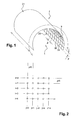
- the panel is made of a flexible material and extends to form a cylinder portion.
- such a shape of the panel makes it possible to significantly increase the apparent size of the panel image on a convex shaped object, the object being intended to be located inside the cylinder portion.
- the front face 20 of the panel 2 comprises a network 3 of fringes alternating 30 and dark 30 light lines, the fringe network 3 having a first series of substantially parallel fringes extending in a first curvilinear direction and in a p-step, and a second series of substantially parallel fringes extending in a second direction substantially perpendicular to the first curvilinear direction, and in step p.
- the panel 2 is made of an opaque material and the lighting means are arranged to illuminate the front face of the panel 2.
- the panel 2 is made of a translucent material and the lighting means are arranged to illuminate the rear face of the panel 2.
- the cameras are fixed on the rear face 21 of the panel 2.
- Each camera has a field of vision and is arranged to capture in their field of vision through the orifices passing through an image of the fringe grating 3 reflected or transmitted by the surface of the object.
- the cameras can be synchronized with each other.
- the panel 2 is made of a flexible material and extends to form substantially a cylinder portion whose generator extends substantially parallel to the second direction of the network 3 fringes.
- the object is intended to be disposed within the cylinder portion.
- the panel 2 is movable between a plurality of positions, the displacement between two successive positions being designed to introduce a predetermined phase shift between two images of the network 3 of fringes reflected or transmitted by the surface of the object.
- the panel 2 is movable along the first and the second direction of the network 3 of fringes respectively between a first and a second plurality of positions, moving between two successive positions of the first and second plurality of positions corresponding to a predetermined integer fraction of the pitch p of the fringe array 3.
- the panel 2 is movable along the first and the second direction of the network 3 of fringes respectively between a first plurality of five positions (denoted j and numbered from 0 to 4) a second plurality of five positions (denoted i and numbered from 0 to 4), the displacement between two successive positions of the first and second plurality of positions corresponding to one fifth of the pitch p of the network 3 of fringes.
- the cameras are arranged to capture the image of the fringe grating 3 reflected or transmitted by the surface of the object for each of the first and second plurality of positions of the panel 2.
- Such a mobility of the support 1 of the object 4 consists of rotations around this point P in order to move an image of the fringe grating 3 reflected by the surface of the object 4 without moving the object 4 itself into the field of view.
- the rotations are performed around axes determined so that the images of the network 3 of fringes reflected by the surface of the object 4 move in directions corresponding to their phase shift.
Abstract
Description
La présente invention se rapporte à une installation de contrôle de la qualité d'une surface d'un objet.The present invention relates to an installation for controlling the quality of a surface of an object.
Le contrôle de la qualité d'une surface peut être réalisé par déflectométrie à décalage de phase.Quality control of a surface can be achieved by phase shift deflectometry.
La déflectométrie à décalage de phase est une technique consistant à déterminer la géométrie d'une surface réfléchissante ou transparente d'un objet par la forme de ses pentes et courbures locales, à partir de la déformation de l'image d'une mire, notamment de type grille, réfléchie ou transmise par la surface de l'objet. Par « mire», on entend un réseau de franges alternant des lignes claires et sombres, généralement à profil sinusoïdal ou binaire à transition franche de luminosité.Phase shift deflectometry is a technique consisting in determining the geometry of a reflective or transparent surface of an object by the shape of its local slopes and curvatures, from the deformation of the image of a test pattern, in particular grid type, reflected or transmitted by the surface of the object. By "pattern" is meant a network of fringes alternating light and dark lines, generally sinusoidal or binary profile with a clear transition of brightness.
La déformation de l'image de la mire est capturée par au moins un moyen de capture d'image, notamment de type caméra, chaque moyen de capture présentant un champ de vision. Le ou chaque moyen de capture est agencé pour capturer dans le champ de vision correspondant une image du réseau de franges réfléchie ou transmise par la surface de l'objet. L'image du réseau de franges réfléchie ou transmise par la surface de l'objet contient un signal périodique formé par la luminance du réseau de franges réfléchie ou transmise par la surface de l'objet.The deformation of the image of the test pattern is captured by at least one image capture means, in particular of the camera type, each capture means having a field of view. The or each capture means is arranged to capture in the corresponding field of view an image of the fringe network reflected or transmitted by the surface of the object. The image of the fringe grating reflected or transmitted by the surface of the object contains a periodic signal formed by the luminance of the fringe grating reflected or transmitted by the surface of the object.
Le signal périodique est échantillonné sur au moins une période avec un minimum de trois échantillons pour une mesure de phase. Puis la carte de phase de l'image du réseau de franges est extraite classiquement des échantillons du signal périodique selon une méthode d'extraction de la composante fondamentale de Fourier.The periodic signal is sampled over at least one period with a minimum of three samples for one phase measurement. Then the phase map of the image of the fringe network is classically extracted from the samples of the periodic signal according to a method of extraction of the fundamental Fourier component.
Pour obtenir une mesure complète des pentes de la surface de l'objet à contrôler, deux directions orthogonales des franges sont nécessaires. En effet, les pentes ont deux composantes ; si la géométrie de la surface à contrôler est décrite dans un repère cartésien (x, y, z) par la fonction z(x, y), les deux composantes des pentes locales sont ∂z/∂x et ∂z/∂y.To obtain a complete measurement of the slopes of the surface of the object to be controlled, two orthogonal directions of the fringes are necessary. Indeed, the slopes have two components; if the geometry of the surface to be controlled is described in a cartesian coordinate system (x, y, z) by the function z (x, y), the two components of the local slopes are ∂z / ∂x and ∂z / ∂y.
Deux techniques utilisées en déflectométrie sont connues de l'état de la technique :
- le décalage de phase temporel,
- le décalage de phase spatial.
- the temporal phase shift,
- the spatial phase shift.
Le décalage de phase temporel nécessite classiquement l'utilisation d'un affichage informatique d'une mire par un moniteur (de type LCD ou plasma) ou d'un vidéoprojecteur projetant sur un écran diffusant (en réflexion ou en transmission).The temporal phase shift conventionally requires the use of a computer display of a test pattern by a monitor (of type LCD or plasma) or a projector projecting on a diffusing screen (in reflection or in transmission).
La mire est déplacée par traitement informatique de manière à introduire un décalage de phase prédéterminé entre deux images du réseau de franges réfléchies ou transmises par la surface de l'objet. L'inconvénient principal du décalage de phase temporel est la limitation de la taille du moniteur qui ne permet pas de réaliser des mesures des pentes pour une surface à contrôler de grande taille. Par « grande taille », on entend une surface présentant une superficie supérieure à 0,5 m2.The pattern is moved by computer processing so as to introduce a predetermined phase shift between two images of the array of fringes reflected or transmitted by the surface of the object. The main disadvantage of the time phase shift is the limitation of the size of the monitor which does not make it possible to measure slopes for a large control surface. "Large size" means a surface area greater than 0.5 m 2 .
Par ailleurs, l'emploi d'un vidéoprojecteur n'est pas adapté aux environnements industriels du fait de sa fragilité, de son coût élevé et de la durée de vie fortement limitée des ampoules utilisées. En outre, l'emploi d'un vidéoprojecteur rend l'installation encombrante car il faut y prévoir l'espace séparant le vidéoprojecteur de l'écran diffusant.In addition, the use of a video projector is not adapted to industrial environments because of its fragility, its high cost and the greatly limited life of the bulbs used. In addition, the use of a video projector makes the installation cumbersome because it must provide the space between the projector of the diffusing screen.
Le décalage de phase spatial utilise une mire fixe. La mesure de la phase de l'image du réseau de franges réfléchie ou transmise par la surface de l'objet est effectuée au voisinage d'un point de la surface de l'objet à partir de la capture d'image d'un pixel d'une caméra visant ce point et par un groupe de pixels contigus. Ainsi, un premier inconvénient du décalage de phase spatial est une limitation de la résolution spatiale de la mesure de phase car plusieurs pixels contigus sont nécessaires pour faire une mesure locale.The spatial phase shift uses a fixed pattern. The measurement of the image phase of the fringe grating reflected or transmitted by the surface of the object is performed in the vicinity of a point of the surface of the object from the image capture of a pixel a camera aimed at that point and a group of contiguous pixels. Thus, a first drawback of the spatial phase shift is a limitation of the spatial resolution of the phase measurement because several contiguous pixels are necessary to make a local measurement.
Par ailleurs, un deuxième inconvénient du décalage de phase spatial est la contrainte que l'image du réseau de franges réfléchie ou transmise par la surface de l'objet ne doit pas être trop déformée afin que la variation de la fréquence spatiale apparente de ladite image soit suffisamment faible pour extraire la phase. Ainsi, seuls des objets quasi plans, quasi sphériques, quasi cylindriques ou quasi toriques peuvent bénéficier d'un contrôle de surface par décalage de phase spatial.Moreover, a second drawback of the spatial phase shift is the constraint that the image of the fringe grating reflected or transmitted by the surface of the object must not be too deformed so that the variation of the apparent spatial frequency of said image is low enough to extract the phase. Thus, only quasi-planar, quasi-spherical, quasi-cylindrical or quasi-toric objects can benefit from a spatial phase offset surface control.
La présente invention vise à remédier en tout ou partie aux inconvénients précités et concerne une installation de contrôle de la qualité d'une surface d'un objet remarquable en ce qu'elle comporte :
- un support de l'objet,
- un panneau comprenant un réseau de franges alternant des lignes claires et sombres, le réseau de franges présentant une première série de franges sensiblement parallèles s'étendant suivant une première direction et selon un premier pas, et une seconde série de franges sensiblement parallèles s'étendant suivant une seconde direction sensiblement perpendiculaire à la première direction, et selon un second pas,
- des moyens d'éclairage agencés pour éclairer le réseau de franges,
- au moins un moyen de capture d'image, notamment de type caméra, le ou chaque moyen de capture présentant un champ de vision, et étant agencé pour capturer dans le champ de vision correspondant une image du réseau de franges réfléchie ou transmise par la surface de l'objet, et
- a support of the object,
- a panel comprising an array of fringes alternating light and dark lines, the fringe array having a first series of substantially parallel fringes extending in a first direction and in a first pitch, and a second series of substantially parallel fringes extending in a second direction substantially perpendicular to the first direction, and in a second step,
- lighting means arranged to illuminate the fringe network,
- at least one image capture means, in particular of the camera type, the or each capture means having a field of view, and being arranged to capture in the corresponding field of view an image of the fringe grating reflected or transmitted by the surface of the object, and
Ainsi, la présence d'un panneau formant une mire permet d'envisager la réalisation d'une mire de grande taille simple à mettre en oeuvre et à faible coût, notamment par impression de lignes sombres croisées sur un panneau de couleur claire, et par là-même permet d'effectuer un contrôle de qualité d'une surface de grande taille telle qu'une surface d'un véhicule automobile, contrairement au décalage de phase temporel. En outre, un tel panneau est robuste et pérenne, ce qui est favorable pour des environnements industriels.Thus, the presence of a panel forming a pattern makes it possible to envisage the production of a large scale that is simple to implement and at a low cost, in particular by printing crossed dark lines on a light-colored panel, and by it itself makes it possible to carry out a quality control of a large surface such as a surface of a motor vehicle, contrary to the temporal phase shift. In addition, such a panel is robust and durable, which is favorable for industrial environments.
Par ailleurs, un tel réseau de franges permet une mesure complète des pentes de la surface à contrôler de l'objet.Furthermore, such a network of fringes allows a complete measurement of the slopes of the surface to be controlled of the object.
Une telle mobilité de l'élément sélectionné dans le groupe comportant le support de l'objet, le panneau et les moyens de capture permet l'introduction du décalage de phase ainsi que le contrôle de la qualité d'une surface d'un objet non nécessairement quasi plane, quasi sphérique, quasi cylindrique ou quasi torique, ce qui n'est pas envisageable dans le décalage de phase spatial.Such mobility of the selected element in the group comprising the support of the object, the panel and the capture means allows the introduction of the phase shift as well as the quality control of a surface of a non-object. necessarily quasi-planar, quasi-spherical, quasi-cylindrical or quasi-toric, which is not conceivable in the spatial phase shift.
Dans un mode de réalisation, le panneau est mobile suivant la première et la seconde direction du réseau de franges respectivement entre une première et une seconde pluralité de positions, le déplacement entre deux positions successives de la première et de la seconde pluralité de positions correspondant respectivement à une fraction entière prédéterminée du premier et du second pas du réseau de franges.In one embodiment, the panel is movable along the first and the second direction of the fringe network respectively between a first and a second plurality of positions, the displacement between two successive positions of the first and second plurality of corresponding positions respectively to a predetermined integer fraction of the first and the second pitch of the fringe network.
Ainsi, une telle mobilité du panneau permet d'introduire un décalage de phase prédéterminé entre deux images du réseau de franges réfléchies ou transmises par la surface de l'objet.Thus, such a mobility of the panel makes it possible to introduce a predetermined phase shift between two images of the network of fringes reflected or transmitted by the surface of the object.
Avantageusement, le ou chaque moyen de capture d'image est agencé pour capturer l'image du réseau de franges réfléchie ou transmise par la surface de l'objet pour chacune de la première et de la seconde pluralité de positions du panneau.Advantageously, the or each image capturing means is arranged to capture the image of the fringe grating reflected or transmitted by the surface of the object for each of the first and second plurality of positions of the panel.
Ainsi, un tel agencement du ou de chaque moyen de capture permet d'optimiser la résolution spatiale de la mesure de phase. En effet, c'est le même pixel qui va capturer le signal périodique généré par le déplacement du panneau. Ce même pixel permet une mesure de la phase correspondant exactement au point de l'objet vu par ce pixel. Un tel agencement du ou de chaque moyen de capture permet de s'affranchir d'une mesure de phase dépendante d'un groupe de pixels contigus.Thus, such an arrangement of the or each capture means makes it possible to optimize the spatial resolution of the phase measurement. Indeed, it is the same pixel that will capture the periodic signal generated by the displacement of the panel. This same pixel allows a measurement of the phase corresponding exactly to the point of the object seen by this pixel. Such an arrangement of the or each capture means makes it possible to dispense with a phase measurement dependent on a group of contiguous pixels.
Selon une forme d'exécution, l'installation comporte des moyens de déplacement du panneau comprenant au moins un premier actionneur et au moins un second actionneur, de préférence du type linéaire électrique ou linéaire pneumatique, le premier et le second actionneur étant agencés pour respectivement déplacer le panneau suivant la première et la seconde direction du réseau de franges.According to one embodiment, the installation comprises means for moving the panel comprising at least a first actuator and at least one second actuator, preferably of linear electric or linear pneumatic type, the first and second actuators being arranged respectively for move the panel following the first and the second direction of the fringe network.
Ainsi, de tels moyens de déplacement assurent la cinématique du panneau suivant la première et la seconde direction du réseau de franges.Thus, such displacement means ensure the kinematics of the panel following the first and the second direction of the fringe network.
Avantageusement, l'installation comporte des moyens de guidage, de préférence des rails de guidage, agencés pour guider le panneau suivant la première et la seconde direction du réseau de franges.Advantageously, the installation comprises guiding means, preferably guide rails, arranged to guide the panel along the first and the second direction of the fringe network.
Ainsi, de tels moyens de guidage permettent d'améliorer la précision de la cinématique du panneau.Thus, such guide means can improve the accuracy of the kinematic panel.
Selon une réalisation particulière, le panneau présente :
- une face dite avant destinée à être orientée vers l'objet, et comprenant le réseau de franges,
- une face dite arrière opposée,
- des orifices traversant ménagés en son sein,
- a so-called front face intended to be oriented towards the object, and comprising the network of fringes,
- a so-called opposite rear face,
- through orifices formed in it,
Selon un mode de réalisation, l'installation comporte un moyen de capture et le support de l'objet est mobile autour du point de la surface de l'objet situé au centre du champ de vision du moyen de capture, lorsque l'objet est disposé sur le support, le déplacement entre deux positions successives du support étant conçu de manière à introduire un décalage de phase prédéterminé entre deux images du réseau de franges réfléchies par la surface de l'objet.According to one embodiment, the installation comprises a capture means and the support of the object is mobile around the point of the surface of the object situated in the center of the field of view of the capture means, when the object is disposed on the support, the displacement between two successive positions of the support being designed to introduce a predetermined phase shift between two images of the network of fringes reflected by the surface of the object.
Ainsi, une telle mobilité du support est une alternative à la mobilité du panneau pour introduire un décalage de phase prédéterminé entre deux images du réseau de franges réfléchies par la surface de l'objet.Thus, such a mobility of the support is an alternative to the mobility of the panel to introduce a predetermined phase shift between two images of the network of fringes reflected by the surface of the object.
Selon un mode de réalisation, le ou chaque moyen de capture est mobile autour du centre du champ de vision correspondant entre la pluralité de positions, le centre du champ de vision correspondant étant destiné à viser un point fixe de la surface de l'objet.According to one embodiment, the or each capture means is movable around the center of the corresponding field of view between the plurality of positions, the center of the corresponding field of view being intended to aim at a fixed point of the surface of the object.
Ainsi, une telle mobilité du ou de chaque moyen de capture est une alternative à la mobilité du panneau et à la mobilité du support pour introduire un décalage de phase prédéterminé entre deux images du réseau de franges réfléchies ou transmises par la surface de l'objet. En outre, une telle mobilité du ou de chaque moyen de capture est particulièrement adaptée « en transmission », c'est-à-dire pour introduire un décalage de phase prédéterminé entre deux images du réseau de franges transmises par la surface de l'objet.Thus, such mobility of the or each capture means is an alternative to the mobility of the panel and the mobility of the support for introducing a predetermined phase shift between two images of the network of fringes reflected or transmitted by the surface of the object. . In addition, such mobility of the or each capture means is particularly suitable "in transmission", that is to say to introduce a predetermined phase shift between two images of the fringe network transmitted by the surface of the object. .
Selon une variante de réalisation, le ou chaque moyen de capture est mobile en translation relativement à la surface de l'objet entre la pluralité de positions, et l'installation comporte des moyens de traitement des images capturées, les moyens de traitement étant configurés pour recaler lesdites images capturées par translation sur un point fixe de la surface de l'objet.According to an alternative embodiment, the or each capture means is movable in translation relative to the surface of the object between the plurality of positions, and the installation comprises means for processing the captured images, the processing means being configured to recaliming said captured images by translation on a fixed point of the surface of the object.
Ainsi, cette variante est particulièrement avantageuse lorsque chaque moyen de capture est mobile en rotation autour du centre du champ de vision correspondant visant un point fixe de la surface de l'objet, ce point fixe pouvant être éloigné du moyen de capture, par exemple de 1,5 à 2 m. Le mouvement du moyen de capture qui est un couplage entre une translation et une rotation d'angle très faible (de l'ordre du degré à quelques degrés) peut s'avérer difficile à mettre en oeuvre pour assurer que l'image capturée dans le champ de vision ne bouge pas au pixel près.Thus, this variant is particularly advantageous when each capture means is rotatable about the center of the corresponding field of view aimed at a fixed point of the surface of the object, this fixed point being remote from the capture means, for example from 1.5 to 2 m. The movement of the capture means, which is a coupling between a translation and a very low angle rotation (of the order of a degree to a few degrees) can prove difficult to implement to ensure that the image captured in the field of vision does not move to the nearest pixel.
En effet, selon la variante de réalisation, le ou chaque moyen de capture est simplement translaté ce qui simplifie le mouvement mécanique, et la visée de la référence qui est le point fixe de la surface de l'objet est assurée par un recalage par translation des images capturées par l'intermédiaire de moyens de traitement.Indeed, according to the variant embodiment, the or each capture means is simply translated which simplifies the mechanical movement, and the aim of the reference which is the fixed point of the surface of the object is ensured by a translational registration of the images captured by means of processing means.
Selon une caractéristique avantageuse, le premier pas du réseau de franges est sensiblement égal au second pas.According to an advantageous characteristic, the first pitch of the fringe network is substantially equal to the second pitch.
Ainsi, l'échantillonnage des signaux périodiques formés par la luminance du réseau de franges réfléchie ou transmise par la surface de l'objet ainsi que l'extraction de phase des échantillons sont simplifiés et nécessitent moins de temps de calcul.Thus, the sampling of the periodic signals formed by the luminance of the fringe grating reflected or transmitted by the surface of the object as well as the phase extraction of the samples are simplified and require less computation time.
Avantageusement, le panneau est réalisé dans une matière souple et s'étend de manière à former une portion de cylindre.Advantageously, the panel is made of a flexible material and extends to form a cylinder portion.
Ainsi, une telle forme du panneau permet d'augmenter de manière significative la taille apparente de l'image du panneau sur un objet de forme convexe, l'objet étant destiné à être situé à l'intérieur de la portion de cylindre.Thus, such a shape of the panel makes it possible to significantly increase the apparent size of the panel image on a convex shaped object, the object being intended to be located inside the cylinder portion.
D'autres caractéristiques et avantages apparaîtront dans la description qui va suivre de trois modes de réalisation d'une installation de contrôle de la qualité d'une surface d'un objet selon l'invention, donnés à titre d'exemples non limitatifs, en référence aux dessins annexés dans lesquels :
- la
figure 1 est une vue partielle d'une installation selon un premier mode de réalisation, - la
figure 2 est une vue schématique d'une matrice de déplacements du panneau illustré à lafigure 1 , - la
figure 3 est une vue partielle schématique d'une installation selon un deuxième mode de réalisation, - la
figure 4 est une vue partielle schématique d'une installation selon un troisième mode de réalisation, - la
figure 5 est une vue analogue à lafigure 3 illustrant une variante d'exécution du deuxième mode de réalisation.
- the
figure 1 is a partial view of an installation according to a first embodiment, - the
figure 2 is a schematic view of a matrix of displacements of the panel illustrated in FIG.figure 1 , - the
figure 3 is a schematic partial view of an installation according to a second embodiment, - the
figure 4 is a schematic partial view of an installation according to a third embodiment, - the
figure 5 is a view similar to thefigure 3 illustrating an alternative embodiment of the second embodiment.
Pour les différentes variantes de réalisation, les mêmes références pourront être utilisées pour des éléments identiques ou assurant la même fonction, par souci de simplification de la description.For the different embodiments, the same references may be used for identical elements or providing the same function, for the sake of simplification of the description.
L'installation de contrôle de la qualité d'une surface d'un objet illustrée à la
un support 1 de l'objet tel qu'un sol,un panneau 2,- des moyens d'éclairage (non représentés), tels que des tubes fluorescents ou un éclairage à diodes électroluminescentes,
- des moyens de capture d'image comportant des caméras (non représentées).
- a
support 1 of the object such as a floor, - a
panel 2, - lighting means (not shown), such as fluorescent tubes or light-emitting diode lighting,
- image capture means comprising cameras (not shown).
Le panneau 2 comprend :
- une
face dite avant 20 destinée à être orientée vers l'objet, - une face dite arrière 21 opposée,
- des orifices traversant (non représentés) ménagés en son sein.
- a so-called
front face 20 intended to be oriented towards the object, - an opposite
opposite face 21, - through orifices (not shown) formed therein.
La face avant 20 du panneau 2 comprend un réseau 3 de franges alternant des lignes claires 30 et sombres 31, le réseau 3 de franges présentant une première série de franges sensiblement parallèles s'étendant suivant une première direction curviligne et selon un pas p, et une seconde série de franges sensiblement parallèles s'étendant suivant une seconde direction sensiblement perpendiculaire à la première direction curviligne, et selon le pas p.The
Selon une forme d'exécution, le panneau 2 est réalisé dans un matériau opaque et les moyens d'éclairage sont agencés pour éclairer la face avant du panneau 2.According to one embodiment, the
Selon une variante d'exécution, le panneau 2 est réalisé dans un matériau translucide et les moyens d'éclairage sont agencés pour éclairer la face arrière du panneau 2.According to an alternative embodiment, the
Les caméras sont fixées sur la face arrière 21 du panneau 2. Chaque caméra présente un champ de vision et est agencée de manière à capturer dans leur champ de vision à travers les orifices traversant une image du réseau 3 de franges réfléchie ou transmise par la surface de l'objet. Avantageusement, les caméras peuvent être synchronisées entre elles.The cameras are fixed on the
Le panneau 2 est réalisé dans une matière souple et s'étend de manière à former sensiblement une portion de cylindre dont la génératrice s'étend sensiblement parallèlement à la seconde direction du réseau 3 de franges. L'objet est destiné à être disposé à l'intérieur de la portion de cylindre.The
Le panneau 2 est mobile entre une pluralité de positions, le déplacement entre deux positions successives étant conçu de manière à introduire un décalage de phase prédéterminé entre deux images du réseau 3 de franges réfléchies ou transmises par la surface de l'objet.The
Pour ce faire, le panneau 2 est mobile suivant la première et la seconde direction du réseau 3 de franges respectivement entre une première et une seconde pluralité de positions, le déplacement entre deux positions successives de la première et de la seconde pluralité de positions correspondant à une fraction entière prédéterminée du pas p du réseau 3 de franges.To do this, the
Dans l'exemple illustré à la
Les caméras sont agencées pour capturer l'image du réseau 3 de franges réfléchie ou transmise par la surface de l'objet pour chacune de la première et de la seconde pluralité de positions du panneau 2.The cameras are arranged to capture the image of the fringe grating 3 reflected or transmitted by the surface of the object for each of the first and second plurality of positions of the
L'installation comporte des moyens de déplacement du panneau 2 (non représentés) comprenant :
- au moins un premier actionneur, pouvant être de type linéaire électrique ou linéaire pneumatique, agencé pour déplacer le panneau 2 suivant la première direction du
réseau 3 de franges, - au moins un second actionneur, pouvant être de type linéaire électrique ou linéaire pneumatique, agencé pour déplacer le panneau 2 suivant la seconde direction du réseau 3 de franges.
- at least one first actuator, which may be of linear electric or linear pneumatic type, arranged to move the
panel 2 along the first direction of thefringe network 3, - at least one second actuator, which may be of linear electric or linear pneumatic type, arranged to move the
panel 2 in the second direction of thenetwork 3 of fringes.
L'installation comporte :
- deux rails de guidage circulaires (non représentés) disposés de part et d'autre du panneau 2 et agencés pour guider le panneau 2 suivant la première direction du
réseau 3 de franges, - deux rails de guidage longitudinaux (non représentés) disposés de part et d'autre du panneau 2 et agencés pour guider le panneau 2 suivant la seconde direction du réseau 3 de franges.
- two circular guide rails (not shown) arranged on either side of the
panel 2 and arranged to guide thepanel 2 in the first direction of thefringe network 3, - two longitudinal guide rails (not shown) arranged on either side of the
panel 2 and arranged to guide thepanel 2 in the second direction of thenetwork 3 of fringes.
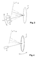
Selon le mode de réalisation illustré à la
- le panneau 2 est fixe,
- l'installation comporte au moins une caméra 5 (une seule est représentée),
chaque caméra 5 est mobile en rotation autour du centre de son champ de vision, le centre du champ de vision visant un point P fixe de la surface d'unobjet 4.
- the
panel 2 is fixed, - the installation comprises at least one camera 5 (only one is shown),
- each
camera 5 is rotatable around the center of its field of view, the center of the field of view aiming at a fixed point P of the surface of anobject 4.
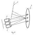
Selon la variante d'exécution illustrée à la
- chaque caméra 5 (une seule est représentée) est mobile en translation relativement à la surface de l'objet 4 entre une pluralité de positions, le centre du champ de vision visant respectivement les points P', P et P" suivant la pluralité de positions,
- l'installation comporte des moyens de traitement (non représentés) des images capturées, les moyens de traitement étant configurés pour recaler lesdites images capturées par translation sur le point P fixe de la surface de l'objet 4.
- each camera 5 (only one is shown) is movable in translation relative to the surface of the
object 4 between a plurality of positions, the center of the field of view aimed respectively at the points P ', P and P "according to the plurality of positions , - the installation comprises processing means (not shown) captured images, the processing means being configured to reset said captured images by translation on the fixed point P of the surface of the
object 4.
Selon le mode de réalisation illustré à la
- le panneau 2 est fixe,
- l'installation comporte une caméra 5,
le support 1d'un objet 4 est mobile autour du point P de la surface de l'objet 4 situé au centre du champ de vision de la caméra 5, le déplacement entre deux positions successives dusupport 1 étant conçu de manière à introduire un décalage de phase prédéterminé entre deux images duréseau 3 de franges réfléchies par la surface de l'objet 4.
- the
panel 2 is fixed, - the installation comprises a
camera 5, - the
support 1 of anobject 4 is movable around the point P of the surface of theobject 4 located in the center of the field of view of thecamera 5, the displacement between two successive positions of thesupport 1 being designed to introduce a predetermined phase shift between two images of thenetwork 3 of fringes reflected by the surface of theobject 4.
Une telle mobilité du support 1 de l'objet 4 consiste en des rotations autour de ce point P afin de déplacer une image du réseau 3 de franges réfléchie par la surface de l'objet 4 sans déplacer l'objet 4 lui-même dans le champ de vision. Les rotations s'effectuent autour d'axes déterminés de manière à ce que les images du réseau 3 de franges réfléchies par la surface de l'objet 4 se déplacent dans des directions correspondant à leur décalage de phase.Such a mobility of the
Bien entendu, les modes de réalisation de l'invention décrits ci-dessus ne présentent aucun caractère limitatif. Des détails et améliorations peuvent y être apportés dans d'autres variantes d'exécution sans pour autant sortir du cadre de l'invention.Of course, the embodiments of the invention described above are not limiting in nature. Details and improvements can be made in other embodiments without departing from the scope of the invention.
Claims (11)
au moins un élément sélectionné dans le groupe comportant le support (1) de l'objet, le panneau (2) et le ou chaque moyen de capture est mobile entre une pluralité de positions, le déplacement entre deux positions successives de chaque élément sélectionné étant conçu de manière à introduire un décalage de phase prédéterminé entre deux images du réseau (3) de franges réfléchies ou transmises par la surface de l'objet (4).
at least one element selected from the group comprising the support (1) of the object, the panel (2) and the or each capture means is movable between a plurality of positions, the displacement between two successive positions of each selected element being designed to introduce a predetermined phase shift between two images of the network (3) of fringes reflected or transmitted by the surface of the object (4).
et en ce que le ou chaque moyen de capture est fixé sur la face arrière (21) du panneau (2) de manière à capturer dans le champ de vision correspondant à travers les orifices traversant une image du réseau (3) de franges réfléchie ou transmise par la surface de l'objet.
and in that the or each capture means is fixed on the rear face (21) of the panel (2) so as to capture in the corresponding field of view through the orifices passing through an image of the grating (3) reflected fringes or transmitted by the surface of the object.
Applications Claiming Priority (1)
| Application Number | Priority Date | Filing Date | Title |
|---|---|---|---|
| FR1002006A FR2960059B1 (en) | 2010-05-11 | 2010-05-11 | INSTALLATION FOR MONITORING THE QUALITY OF A SURFACE OF AN OBJECT |
Publications (1)
| Publication Number | Publication Date |
|---|---|
| EP2386848A1 true EP2386848A1 (en) | 2011-11-16 |
Family
ID=43243672
Family Applications (1)
| Application Number | Title | Priority Date | Filing Date |
|---|---|---|---|
| EP11165611A Withdrawn EP2386848A1 (en) | 2010-05-11 | 2011-05-11 | Installation for the quality control of the surface of an object |
Country Status (3)
| Country | Link |
|---|---|
| US (1) | US20110285987A1 (en) |
| EP (1) | EP2386848A1 (en) |
| FR (2) | FR2960059B1 (en) |
Cited By (3)
| Publication number | Priority date | Publication date | Assignee | Title |
|---|---|---|---|---|
| EP2977756A1 (en) | 2014-07-24 | 2016-01-27 | AGC Glass Europe | Method and installation for imaging a fragmentation pattern formed in a tempered glass panel |
| EP3792619A1 (en) * | 2019-09-11 | 2021-03-17 | Proov Station | Assembly for detecting faults on a body of a motor vehicle |
| FR3101420A1 (en) | 2019-09-30 | 2021-04-02 | Saint-Gobain Glass France | Method for evaluating the optical quality of a delimited area of a glazing |
Families Citing this family (7)
| Publication number | Priority date | Publication date | Assignee | Title |
|---|---|---|---|---|
| EP3035882B1 (en) * | 2013-08-13 | 2018-03-28 | Brainlab AG | Moiré marker device for medical navigation |
| US9952039B2 (en) | 2015-06-26 | 2018-04-24 | Glasstech, Inc. | System and method for measuring reflected optical distortion in contoured panels having specular surfaces |
| US9952037B2 (en) | 2015-06-26 | 2018-04-24 | Glasstech, Inc. | System and method for developing three-dimensional surface information corresponding to a contoured sheet |
| US9470641B1 (en) | 2015-06-26 | 2016-10-18 | Glasstech, Inc. | System and method for measuring reflected optical distortion in contoured glass sheets |
| US9851200B2 (en) | 2015-06-26 | 2017-12-26 | Glasstech, Inc. | Non-contact gaging system and method for contoured panels having specular surfaces |
| US9841276B2 (en) | 2015-06-26 | 2017-12-12 | Glasstech, Inc. | System and method for developing three-dimensional surface information corresponding to a contoured glass sheet |
| US9933251B2 (en) | 2015-06-26 | 2018-04-03 | Glasstech, Inc. | Non-contact gaging system and method for contoured glass sheets |
Citations (5)
| Publication number | Priority date | Publication date | Assignee | Title |
|---|---|---|---|---|
| GB2308656A (en) * | 1995-12-28 | 1997-07-02 | Nissan Motor | Surface defect inspection apparatus |
| US20070177159A1 (en) * | 2006-01-26 | 2007-08-02 | Kim Min Y | Method for measuring three-dimension shape |
| WO2009007130A1 (en) * | 2007-07-12 | 2009-01-15 | Carl Zeiss Ag | Method and device for the optical inspection of a surface of an object |
| US20090128685A1 (en) * | 2005-11-10 | 2009-05-21 | Obe Ohnmacht & Baumgartner Gmbh & Co. Kg | Camera Chip, Camera and Method for Image Recording |
| EP2236979A2 (en) * | 2009-04-03 | 2010-10-06 | Carl Zeiss OIM GmbH | Method and device for optical inspection of an at least partially reflective surface on an object |
Family Cites Families (5)
| Publication number | Priority date | Publication date | Assignee | Title |
|---|---|---|---|---|
| US5069548A (en) * | 1990-08-08 | 1991-12-03 | Industrial Technology Institute | Field shift moire system |
| DE4130237A1 (en) * | 1991-09-11 | 1993-03-18 | Zeiss Carl Fa | METHOD AND DEVICE FOR THE THREE-DIMENSIONAL OPTICAL MEASUREMENT OF OBJECT SURFACES |
| US5636025A (en) * | 1992-04-23 | 1997-06-03 | Medar, Inc. | System for optically measuring the surface contour of a part using more fringe techniques |
| JP2002296020A (en) * | 2001-03-30 | 2002-10-09 | Nidek Co Ltd | Surface shape measuring instrument |
| US7433058B2 (en) * | 2004-07-12 | 2008-10-07 | Solvision Inc. | System and method for simultaneous 3D height measurements on multiple sides of an object |
-
2010
- 2010-05-11 FR FR1002006A patent/FR2960059B1/en active Active
-
2011
- 2011-05-11 US US13/105,289 patent/US20110285987A1/en not_active Abandoned
- 2011-05-11 EP EP11165611A patent/EP2386848A1/en not_active Withdrawn
- 2011-06-08 FR FR1155020A patent/FR2960060B1/en active Active
Patent Citations (5)
| Publication number | Priority date | Publication date | Assignee | Title |
|---|---|---|---|---|
| GB2308656A (en) * | 1995-12-28 | 1997-07-02 | Nissan Motor | Surface defect inspection apparatus |
| US20090128685A1 (en) * | 2005-11-10 | 2009-05-21 | Obe Ohnmacht & Baumgartner Gmbh & Co. Kg | Camera Chip, Camera and Method for Image Recording |
| US20070177159A1 (en) * | 2006-01-26 | 2007-08-02 | Kim Min Y | Method for measuring three-dimension shape |
| WO2009007130A1 (en) * | 2007-07-12 | 2009-01-15 | Carl Zeiss Ag | Method and device for the optical inspection of a surface of an object |
| EP2236979A2 (en) * | 2009-04-03 | 2010-10-06 | Carl Zeiss OIM GmbH | Method and device for optical inspection of an at least partially reflective surface on an object |
Cited By (7)
| Publication number | Priority date | Publication date | Assignee | Title |
|---|---|---|---|---|
| EP2977756A1 (en) | 2014-07-24 | 2016-01-27 | AGC Glass Europe | Method and installation for imaging a fragmentation pattern formed in a tempered glass panel |
| WO2016012321A1 (en) | 2014-07-24 | 2016-01-28 | Agc Glass Europe | Method and installation for imaging a fragmentation pattern formed in a tempered glass panel |
| EP3792619A1 (en) * | 2019-09-11 | 2021-03-17 | Proov Station | Assembly for detecting faults on a body of a motor vehicle |
| WO2021048066A1 (en) * | 2019-09-11 | 2021-03-18 | Proov Station | Assembly for detecting defects on a motor vehicle bodywork |
| US11965836B2 (en) | 2019-09-11 | 2024-04-23 | Proov Station | Assembly for detecting defects on a motor vehicle bodywork |
| FR3101420A1 (en) | 2019-09-30 | 2021-04-02 | Saint-Gobain Glass France | Method for evaluating the optical quality of a delimited area of a glazing |
| WO2021063847A1 (en) | 2019-09-30 | 2021-04-08 | Saint-Gobain Glass France | Method for evaluating the optical quality of a delimited zone of a glazing |
Also Published As
| Publication number | Publication date |
|---|---|
| FR2960059A1 (en) | 2011-11-18 |
| US20110285987A1 (en) | 2011-11-24 |
| FR2960059B1 (en) | 2012-12-28 |
| FR2960060B1 (en) | 2012-08-31 |
| FR2960060A1 (en) | 2011-11-18 |
Similar Documents
| Publication | Publication Date | Title |
|---|---|---|
| EP2386848A1 (en) | Installation for the quality control of the surface of an object | |
| JP6681844B2 (en) | Remote visual inspection image capture system and method | |
| FR2975776A1 (en) | Installation for controlling painting quality of surface of object i.e. car body, has flexible electroluminescent bands whose controlling unit is programmed to introduce phase shift between images of array of fringes projected on surface | |
| FR2721395A1 (en) | Method for locating a trihedron in space and device for implementing this method. | |
| FR2899326A1 (en) | Object`s e.g. finger, position determining method for e.g. alphanumeric data input field, involves arranging emitter with receivers in proximity to zone, turning on emitter and determining object`s position based on comparison of signals | |
| EP3260957B1 (en) | Device for controlling the braking force of a trackball, and associated trackball | |
| EP2108921A1 (en) | Device for testing surface quality | |
| FR2921719A1 (en) | Physical object e.g. apple, three-dimensional surface's synthesis image creating method for e.g. industrial farm, involves calculating depth coordinate measured at axis for each point of dusty seeds from projection of point on surface | |
| US20150319418A1 (en) | Devices and methods for generating a 3d imaging dataset of an object | |
| JP6085188B2 (en) | Pattern inspection device | |
| FR2658328A1 (en) | ELECTRICALLY CONTROLLED ZOOM LENS BARREL. | |
| CA2880145A1 (en) | Method for the non-destructive testing of a blade preform | |
| EP3507542B1 (en) | Lighting and/or signalling device, in particular for an automotive vehicle | |
| EP2616764A1 (en) | Device and method for measuring the shape of a mirror or of a specular surface | |
| FR3070637B1 (en) | OPTICAL TOUCH PALLET ON DRIVET WHEEL FOR FINGER DETECTION | |
| EP2936281B1 (en) | Interface module | |
| FR3028222A1 (en) | TOUCH PALLET SYSTEM FORMING A MAN-MACHINE INTERFACE ADAPTED ON A VEHICLE WHEEL | |
| WO2010072912A1 (en) | Device for three-dimensional scanning with dense reconstruction | |
| WO2006096264A3 (en) | Reflection spectroscopic means for detecting patterned objects | |
| JP6508763B2 (en) | Surface inspection device | |
| EP0756152A1 (en) | Method and device for detecting the state of the surface of parts with a reflecting surface, applicable for controlling the roughness of polished parts | |
| FR3001564A1 (en) | SYSTEM FOR DETERMINING A THREE-DIMENSIONAL IMAGE OF AN ELECTRONIC CIRCUIT | |
| EP4118479A1 (en) | Method for acquiring an image of a celestial body and apparatus for implementing the method | |
| FR2921732A1 (en) | Contactless scanning device for constructing synthesis image of apple in e.g. industrial field, has camera including sensor placed in optical axle, where distance between sensor and mirror is less than distance between pattern and mirror | |
| WO2014102382A1 (en) | Device for marking a sample, and observation system comprising such a marking device |
Legal Events
| Date | Code | Title | Description |
|---|---|---|---|
| AK | Designated contracting states |
Kind code of ref document: A1 Designated state(s): AL AT BE BG CH CY CZ DE DK EE ES FI FR GB GR HR HU IE IS IT LI LT LU LV MC MK MT NL NO PL PT RO RS SE SI SK SM TR |
|
| AX | Request for extension of the european patent |
Extension state: BA ME |
|
| PUAI | Public reference made under article 153(3) epc to a published international application that has entered the european phase |
Free format text: ORIGINAL CODE: 0009012 |
|
| 17P | Request for examination filed |
Effective date: 20120510 |
|
| 17Q | First examination report despatched |
Effective date: 20180309 |
|
| STAA | Information on the status of an ep patent application or granted ep patent |
Free format text: STATUS: THE APPLICATION IS DEEMED TO BE WITHDRAWN |
|
| 18D | Application deemed to be withdrawn |
Effective date: 20180920 |