EP2386819A1 - Firing device for an initiator - Google Patents
Firing device for an initiator Download PDFInfo
- Publication number
- EP2386819A1 EP2386819A1 EP20110164938 EP11164938A EP2386819A1 EP 2386819 A1 EP2386819 A1 EP 2386819A1 EP 20110164938 EP20110164938 EP 20110164938 EP 11164938 A EP11164938 A EP 11164938A EP 2386819 A1 EP2386819 A1 EP 2386819A1
- Authority
- EP
- European Patent Office
- Prior art keywords
- voltage
- initiator
- firing device
- firing
- thyristor
- Prior art date
- Legal status (The legal status is an assumption and is not a legal conclusion. Google has not performed a legal analysis and makes no representation as to the accuracy of the status listed.)
- Granted
Links
Images

Classifications
-
- F—MECHANICAL ENGINEERING; LIGHTING; HEATING; WEAPONS; BLASTING
- F42—AMMUNITION; BLASTING
- F42B—EXPLOSIVE CHARGES, e.g. FOR BLASTING, FIREWORKS, AMMUNITION
- F42B3/00—Blasting cartridges, i.e. case and explosive
- F42B3/10—Initiators therefor
- F42B3/18—Safety initiators resistant to premature firing by static electricity or stray currents
-
- F—MECHANICAL ENGINEERING; LIGHTING; HEATING; WEAPONS; BLASTING
- F42—AMMUNITION; BLASTING
- F42B—EXPLOSIVE CHARGES, e.g. FOR BLASTING, FIREWORKS, AMMUNITION
- F42B3/00—Blasting cartridges, i.e. case and explosive
- F42B3/10—Initiators therefor
- F42B3/113—Initiators therefor activated by optical means, e.g. laser, flashlight
-
- F—MECHANICAL ENGINEERING; LIGHTING; HEATING; WEAPONS; BLASTING
- F42—AMMUNITION; BLASTING
- F42B—EXPLOSIVE CHARGES, e.g. FOR BLASTING, FIREWORKS, AMMUNITION
- F42B3/00—Blasting cartridges, i.e. case and explosive
- F42B3/10—Initiators therefor
- F42B3/12—Bridge initiators
- F42B3/121—Initiators with incorporated integrated circuit
Definitions
- the present invention relates to a firing device for an initiator.
- the initiator electric
- the firing device will be of the type to enable the ignition of the initiator by the production of heat, in particular by Joule effect or by radiation.
- a projected layer detonator for initiating a secondary safety explosive.
- an electrical conductor produces a plasma that is used to propel at high speed a small projectile delivering the shock wave necessary for the priming of the secondary explosive.
- Such a detonator requires a voltage greater than or equal to 2,000 V and a voltage rise time of less than 1 of a complex power supply and a low inductance connection that is very demanding in use.
- This particularly high voltage allows the projected layer detonator to meet the safety standards of the STANAG 4560 requiring in particular the initiator not to react when an alternating current of 500 V (with peaks of 710 V) is connected directly to its terminals Otherwise, the initiator must present a mechanical interruption of the pyrotechnic chain downstream of the energetic material.
- an optical detonator in which a laser emitted by a laser source (preferably a laser diode) ignites a secondary explosive disposed in a first stage which propels a small projectile delivering the shock wave necessary for priming. second stage secondary explosive.
- a laser source preferably a laser diode
- Such a detonator has many advantages, including that of requiring very little energy (a laser diode requires less than 2 V and less than 1 A to emit light), to be compact (the laser diode is less cumbersome a low voltage / high voltage converter), and to be very sensitive to static electricity (the optical fiber may be several hundred meters long, the laser diode can be integrated in the protected enclosure of the computer).
- the "laser diode - fiber - opto-pyrotechnic initiator" assembly is assimilated for the first time to an electrical initiator in the third edition of the STANAG 4368 standard because the laser diode is an electrical component. Consequently, since 2 V is sufficient to initiate the laser diode, such a detonator can not remain insensitive to an AC voltage of 500 V and, in order to comply with the security standard of STANAG 4560 mentioned above, it must have an optical line interruption. upstream of the energy material initiated by the laser light.
- an optical switch disposed on the optical fiber is bulky, has an additional cost and does not support severe environments (mechanical and thermal) experienced by some initiators.
- the present invention aims to provide a firing device allowing the initiator with which it is associated to be insensitive to AC voltages of 500 V (and therefore not to require a line interruption), while being of a small footprint.
- WO2008 / 11223 discloses protecting the heating element of an initiator by an electrical element, which in itself switches from an insulating state to a conductive state, and only from a certain voltage at its terminals. But this electric element does not play the role of a switch: the switch is added in series to the protection element.
- FR 2408114 and FR 2866703 also refer to the same type of protection as above. In FR 2408114 , it is about various electronic components where the thyristor is used like switch controlled by its trigger. In FR 2866703 , the element is called micro-switch (micro-switch) and is understood as a cleachable insulator or a spark gap.
- a firing device of an initiator comprising a firing member adapted to generate heat to initiate an energetic material disposed in the initiator, an electric switch arranged in series with the firing member and passing from an open state to a closed state by the application at its terminals of a voltage greater than a closing voltage.
- the electrical switch comprises at least one thyristor having an unused trigger and a corresponding overturning voltage (ie equal to) the closing voltage.
- TVS are different components (made of avalanche diodes). They have reversal voltages which are in this case too weak.
- the firing element be a resistive element (for an electrical initiator) or a laser diode (for an optical initiator).
- the electrical switch is chosen so that its closing voltage is greater than 500 V (AC voltage), which corresponds to peaks of 710 V.
- the electrical switch is chosen so that its closing voltage is less than 1000 V.
- the invention relates to a firing device 1 for igniting an electric initiator.
- an initiator can be used for firing pyromechanisms or thrusters.
- the devices for firing powder or explosive are concerned.
- the firing device 1 comprises a firing member 2, 3 which is adapted to generate heat for the initiation of an energetic material disposed in the initiator.
- the firing member is a laser diode 2 which makes it possible to generate a laser light which, after focusing, makes it possible to ignite the energetic material enclosed in the initiator.
- the laser diode 2 begins to conduct the electric current from a threshold of voltage (Udl curve) and, from a minimum intensity therethrough, to emit a light whose power is proportional to this intensity (curve L).
- the firing member is a resistive element 3 (here, an electric resistor 3) which generates, by Joule effect, heat to light the energetic material enclosed in the initator.
- the intensity passing through the resistor 3 is proportional to the voltage at its terminals (curve Ur), and the power delivered is proportional to the square of this intensity.
- the firing device 1 also comprises an electric switch 4 which is connected in series with the firing member 2, 3 and which goes from an open state to a closed state by the application of a higher voltage at a closing voltage. More specifically, the electric switch 4 comprises (at least) a thyristor 4 whose trigger is not used, with a reversal voltage equal to the closing voltage. In the embodiments of figures 1,2 , the electric switch 4 is a single thyristor.
- a thyristor typically, such a thyristor, is intended to be used with a voltage lower than its inverting voltage, and to go from its open state to its closed state by the application of an electrical pulse on its trigger.
- the trigger is not used, the property of the thyristor used is the transition from its open state to its closed state following the application, between its cathode and its anode, of a voltage greater than its voltage. reversal (see curve Ut of Figures 1 and 2 ).
- the firing device 1 does not conduct current as long as the closing voltage of the electric switch 4 is not reached (cf. Figures 3 and 4 where the intensity passing through it remains zero).
- this closing voltage is reached, the firing device 1 behaves like the firing member 2, 3 alone with a slightly higher voltage (see U curves of FIG. Figures 1 and 2 ).
- the figure 5 illustrates the behavior of a firing device 1 following the application of a voltage of 1000 V at its terminals: once the voltage has reached the reversal voltage of the thyristor with electrical switch function 4 ( here, 900 V), an electric current passes through the device, which allows the ignition of the associated initiator.
- the electrical switch 4 and the initiation member 2, 3 can be put in the same housing so as to make only one component (with only two connections coming out of the housing - the trigger is not used).
- the electric switch 4 and the heating element 2, 3 can be placed side by side or fused on the same substrate.
- an electrical switch 4 whose closing voltage (the reversing voltage in the case of a thyristor) is greater than the peaks of 710 V of a 500 V AC voltage makes it possible to meet the safety standard STANAG 4560, without line breaks.
- a firing device 1 makes it possible to have an initiator of high reliability and of a high degree of operational safety, handling and implementation.
- the costs of electrical switches such as thyristors or triacs are low, which makes it possible to produce very high initiators. security at a much lower price than those currently available on the market.
- an electrical switch 4 whose closing voltage (the inverting voltage in the case of a thyristor) is less than 1000 V makes it possible to have a simple implementation and thus to miniaturize the firing device 1. For example, it is possible to use such a device for firing four impellers embedded in a projectile whose diameter is 30 mm.
- an electrical switch 4 whose reversal voltage is barely higher than that authorized by the regulations (typically, from 800 V).
- an igniter is a trigger device that produces a deflagration (burning).
- an optical initiator In the case of an optical initiator (igniter or detonator), it may comply with one of the requests EP 1 067 356 , EP 1 067 357 , EP 1 306 643 and EP 1 742 009 .
- the resistive element 3 can also be any passive electronic component (resistor or capacitor) or active (diode or transistor) for transmitting its heating to the energy material with good efficiency. Since the Joule effect does not allow a secondary explosive to be detonated, it is therefore necessary to use a two-stage detonator with a deflagration-detonation transition or a shock-detonation transition. For reasons of reliability, shock-detonation operation is preferred.
- the resistive element may be a tantalum capacitor which has the advantages of being of small size, of being able to be easily implemented, and of having two different impedance curves according to its direction of use: this capacitor can be likened to a diac when it is solicited live because it has a negative resistance slope beyond a limit, or diode live when it is invoked in reverse because it has a positive resistance slope beyond a threshold.
- the initiator with which the firing device is associated has the following three advantages: reliable operation with less than 1000 V (and therefore simplicity of implementation), holding, with success and without alteration, tests of 500 V AC, and use of insensitive active substances.
- the electric switch could be a triac.
- the figures 6.7 correspond to the montages of the figures 1,2 , respectively, except that the thyristor has been replaced by the triac.
- the triac is an electronic component equivalent to two thyristors (or semiconductor controlled rectifier (SCR) or SCRs mounted in parallel, but head to tail, a triac is sometimes also called a bidirectional thyristor and has the same properties. than those of such a thyristor, and can be used here in the same way as the thyristor, instead of it, as long as it has the same value of reversal voltage.It can even be considered as more practical in the case of a resistive element initiator, since it can be used indifferently in both directions of current flow and does not require registration.
- SCR semiconductor controlled rectifier
- the firing device 1 comprising the firing member, respectively 2 and 3, adapted to generate heat for the initiation of an energetic material disposed in the electric initiator.
- the firing member is the laser diode 2.
- the firing member is the resistive element 3.
- the firing device 1 also comprises the electric switch 4, which here comprises a triac, and which is connected in series with the firing member 2, 3. This triac therefore goes from an open state to a closed state by the application of a voltage greater than a closing voltage.
Landscapes
- Engineering & Computer Science (AREA)
- General Engineering & Computer Science (AREA)
- Physics & Mathematics (AREA)
- Optics & Photonics (AREA)
- Computer Hardware Design (AREA)
- Microelectronics & Electronic Packaging (AREA)
- Air Bags (AREA)
- Furnace Details (AREA)
- Electronic Switches (AREA)
Abstract
Description
La présente invention concerne un dispositif de mise à feu pour un initiateur. Favorablement l'initiateur, électrique, sera un initiateur pyrotechnique, a priori pilotable. Ce pourra être typiquement un inflammateur ou un détonateur. En particulier, le dispositif de mise à feu sera du type à permettre l'allumage de l'initiateur par la production de chaleur, notamment par effet Joule ou par rayonnement.The present invention relates to a firing device for an initiator. Favorably the initiator, electric, will be a pyrotechnic initiator, a priori pilotable. It may be typically an igniter or a detonator. In particular, the firing device will be of the type to enable the ignition of the initiator by the production of heat, in particular by Joule effect or by radiation.
On connaît un détonateur à couche projetée qui permet d'amorcer un explosif secondaire de sécurité. Dans un tel détonateur, un conducteur électrique produit un plasma qui sert à propulser à haute vitesse un petit projectile délivrant l'onde de choc nécessaire à l'amorçage de l'explosif secondaire. Un tel détonateur nécessite une tension supérieure ou égale à 2 000 V et un temps de montée en tension inférieur à 1 d'une alimentation électrique complexe et une connectique basse inductance très exigeante à l'emploi.A projected layer detonator is known for initiating a secondary safety explosive. In such a detonator, an electrical conductor produces a plasma that is used to propel at high speed a small projectile delivering the shock wave necessary for the priming of the secondary explosive. Such a detonator requires a voltage greater than or equal to 2,000 V and a voltage rise time of less than 1 of a complex power supply and a low inductance connection that is very demanding in use.
Cette tension particulièrement élevée permet au détonateur à couche projetée de répondre aux normes de sécurité du STANAG 4560 imposant notamment à l'initiateur de ne pas réagir quand un courant alternatif de 500 V (avec des pics de 710 V) est branché directement sur ses bornes, faute de quoi l'initiateur doit présenter une interruption mécanique de chaine pyrotechnique en aval du matériau énergétique.This particularly high voltage allows the projected layer detonator to meet the safety standards of the STANAG 4560 requiring in particular the initiator not to react when an alternating current of 500 V (with peaks of 710 V) is connected directly to its terminals Otherwise, the initiator must present a mechanical interruption of the pyrotechnic chain downstream of the energetic material.
Cependant cette tension particulièrement élevée présente l'inconvénient d'avoir un dispositif de mise à feu assez encombrant, limitant en conséquence l'emploi des détonateurs à couche projetée.However, this particularly high voltage has the disadvantage of having a rather cumbersome firing device, consequently limiting the use of the projected layer detonators.
Par ailleurs, on connaît un détonateur optique dans lequel un laser émis par une source laser (de préférence, une diode laser) allume un explosif secondaire disposé dans un premier étage qui propulse un petit projectile délivrant l'onde de choc nécessaire à l'amorçage de l'explosif secondaire du second étage.Furthermore, an optical detonator is known in which a laser emitted by a laser source (preferably a laser diode) ignites a secondary explosive disposed in a first stage which propels a small projectile delivering the shock wave necessary for priming. second stage secondary explosive.
Un tel détonateur présente de nombreux avantages, notamment celui de nécessiter très peu d'énergie (une diode laser nécessite moins de 2 V et moins d'1 A pour émettre la lumière), d'être peu encombrant (la diode laser est moins encombrante qu'un convertisseur basse tension / haute tension), et d'être peu sensible à l'électricité statique (la fibre optique pouvant avoir plusieurs centaines de mètres de longueur, la diode laser peut être intégrée dans l'enceinte protégée du calculateur).Such a detonator has many advantages, including that of requiring very little energy (a laser diode requires less than 2 V and less than 1 A to emit light), to be compact (the laser diode is less cumbersome a low voltage / high voltage converter), and to be very sensitive to static electricity (the optical fiber may be several hundred meters long, the laser diode can be integrated in the protected enclosure of the computer).
Cependant, l'ensemble « diode laser - fibre - initiateur opto-pyrotechnique » est assimilé pour la première fois à un initiateur électrique dans la troisième édition de la norme STANAG 4368 du fait que la diode laser est un composant électrique. En conséquence, vu que 2 V suffisent pour initier la diode laser, un tel détonateur ne peut rester insensible à une tension alternative de 500 V et, pour respecter la norme de sécurité du STANAG 4560 précité, il doit présenter une interruption de ligne optique en amont du matériau énergétique initié par la lumière laser.However, the "laser diode - fiber - opto-pyrotechnic initiator" assembly is assimilated for the first time to an electrical initiator in the third edition of the STANAG 4368 standard because the laser diode is an electrical component. Consequently, since 2 V is sufficient to initiate the laser diode, such a detonator can not remain insensitive to an AC voltage of 500 V and, in order to comply with the security standard of STANAG 4560 mentioned above, it must have an optical line interruption. upstream of the energy material initiated by the laser light.
Or un interrupteur optique disposé sur la fibre optique est encombrant, présente un coût supplémentaire et ne supporte pas les environnements sévères (mécaniques et thermiques) que subissent certains initiateurs.Or an optical switch disposed on the optical fiber is bulky, has an additional cost and does not support severe environments (mechanical and thermal) experienced by some initiators.
La présente invention vise à réaliser un dispositif de mise à feu permettant à l'initiateur auquel il est associé d'être insensible aux tensions alternatives de 500 V (et donc de ne pas nécessiter une interruption de ligne), tout en étant d'un encombrement faible.The present invention aims to provide a firing device allowing the initiator with which it is associated to be insensitive to AC voltages of 500 V (and therefore not to require a line interruption), while being of a small footprint.
Ainsi, est déjà connu un dispositif de mise à feu d'un initiateur, le dispositif comprenant un organe de mise à feu adapté à générer de la chaleur pour initier un matériau énergétique disposé dans l'initiateur, un interrupteur électrique disposé en série avec l'organe de mise à feu et passant d'un état ouvert à un état fermé par l'application à ses bornes d'une tension supérieure à une tension de fermeture.Thus, it is already known a firing device of an initiator, the device comprising a firing member adapted to generate heat to initiate an energetic material disposed in the initiator, an electric switch arranged in series with the firing member and passing from an open state to a closed state by the application at its terminals of a voltage greater than a closing voltage.
Mais ceci ne répond pas à la problématique précitée posée.But this does not answer the aforementioned problematic.
Une solution proposée prévoit à cet égard que l'interrupteur électrique comprenne au moins un thyristor ayant une gâchette non utilisée et une tension de retournement correspondant (ie. égale) à la tension de fermeture.A proposed solution provides in this regard that the electrical switch comprises at least one thyristor having an unused trigger and a corresponding overturning voltage (ie equal to) the closing voltage.
Ainsi, c'est l'interrupteur lui-même qui va être l'élément de protection.Thus, it is the switch itself that will be the protection element.
A noter également que dans
En outre, dans les documents de l'art antérieur, le thyristor n'a été est mentionné que dans sa fonction normale d'interrupteur piloté par sa gâchette. Il n'était pas utilisé en dehors de sa fonction nominale et de ses limites, contrairement à ce que prévoit l'invention.In addition, in the documents of the prior art, the thyristor was only mentioned in its normal function of switch controlled by its trigger. It was not used outside of its nominal function and its limits, contrary to the invention.
On conseille que l'organe de mise à feu soit un élément résistif (pour un initiateur électrique) ou une diode laser (pour un initiateur optique).It is recommended that the firing element be a resistive element (for an electrical initiator) or a laser diode (for an optical initiator).
Afin de répondre à la norme de sécurité du STANAG 4560, l'interrupteur électrique est choisi de façon à ce que sa tension de fermeture soit supérieure à 500 V (tension alternative), ce qui correspond à des pics de 710 V. En outre, afin d'avoir un encombrement le plus faible possible et une mise en oeuvre simple, l'interrupteur électrique est choisi de façon que sa tension de fermeture soit inférieure à 1 000 V.In order to meet the STANAG 4560 safety standard, the electrical switch is chosen so that its closing voltage is greater than 500 V (AC voltage), which corresponds to peaks of 710 V. In addition, in order to have the smallest possible footprint and a simple implementation, the electrical switch is chosen so that its closing voltage is less than 1000 V.
D'autres particularités et avantages apparaîtront dans les modes de réalisation donnés à titre d'exemples non limitatifs et illustrés par les dessins mis en annexe dans lesquels :
- La
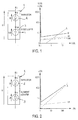
figure 1 représente un schéma d'un dispositif de mise à feu conforme à un premier mode de réalisation, le dispositif comprenant, en série, un thyristor et une diode, lafigure 1 comprenant également un diagramme représentant la tension U et la puissance lumineuse L en fonction de l'intensité I, - La
figure 2 représente un dispositif de mise à feu conforme à un second mode de réalisation, le dispositif comprenant, en série, un thyristor et un élément résistif, lafigure 2 comprenant également un diagramme représentant la tension U en fonction de l'intensité I, - La
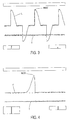
figure 3 représente l'intensité traversant le dispositif de mise à feu du premier mode de réalisation pour un courant alternatif ayant des pointes de 660 V ; - La
figure 4 représente l'intensité traversant le dispositif de mise à feu du premier mode de réalisation suite à l'application d'une tension de 800 V ; - La
figure 5 représente l'intensité traversant le dispositif de mise à feu du premier mode de réalisation suite à l'application d'une tension de 1000 V, et - Les
figures 6,7 représentent chacune un schéma d'un dispositif de mise à feu conforme à un autre mode de réalisation, le dispositif comprenant, en série,figure 6 , un triac et une diode et,figure 7 , un triac et un élément résistif.
- The
figure 1 represents a diagram of a firing device according to a first embodiment, the device comprising, in series, a thyristor and a diode, thefigure 1 also comprising a diagram representing the voltage U and the light power L as a function of the intensity I, - The
figure 2 represents a firing device according to a second embodiment, the device comprising, in series, a thyristor and a resistive element, thefigure 2 also comprising a diagram representing the voltage U as a function of the intensity I, - The
figure 3 represents the intensity through the firing device of the first embodiment for an alternating current having peaks of 660 V; - The
figure 4 represents the intensity passing through the firing device of the first embodiment following the application of a voltage of 800 V; - The
figure 5 represents the intensity passing through the firing device of the first embodiment following the application of a voltage of 1000 V, and - The
figures 6.7 each represent a diagram of a firing device according to another embodiment, the device comprising, in series,figure 6 , a triac and a diode and,figure 7 , a triac and a resistive element.
L'invention concerne un dispositif de mise à feu 1 permettant l'allumage d'un initiateur électrique. Un tel initiateur peut servir à la mise à feu de pyromécanismes ou de propulseurs.The invention relates to a
Sont concernés les dispositifs de mise à feu de poudre ou d'explosif.The devices for firing powder or explosive are concerned.
Le dispositif de mise à feu 1 comprend un organe de mise à feu 2, 3 qui est adapté à générer de la chaleur permettant l'initiation d'un matériau énergétique disposé dans l'initiateur.The
Dans le premier mode de réalisation, l'organe de mise à feu est une diode laser 2 qui permet de générer une lumière laser qui, après focalisation, permet d'allumer le matériau énergétique enfermé dans l'initiateur.In the first embodiment, the firing member is a
Comme illustré à la
Dans le second mode de réalisation, l'organe de mise à feu est un élément résistif 3 (ici, une résistance électrique 3) qui génère, par effet Joule, de la chaleur permettant d'allumer le matériau énergétique enfermé dans l'inïtiateur.In the second embodiment, the firing member is a resistive element 3 (here, an electric resistor 3) which generates, by Joule effect, heat to light the energetic material enclosed in the initator.
Comme illustré à la
Le dispositif de mise à feu 1 comprend également un interrupteur électrique 4 qui est monté en série avec l'organe de mise à feu 2, 3 et qui passe d'un état ouvert à un état fermé par l'application d'une tension supérieure à une tension de fermeture. De façon plus précise, l'interrupteur électrique 4 comprend (au moins) un thyristor 4 dont la gâchette n'est pas utilisée, avec une la tension de retournement égale à la tension de fermeture. Dans les modes de réalisation des
typiquement, un tel thyristor, est prévu pour être employé avec une tension inférieure à sa tension de retournement, et pour passer de son état ouvert à son état fermé par l'application d'une impulsion électrique sur sa gâchette. Dans la présente invention la gâchette n'est pas employée, la propriété du thyristor utilisée est le passage de son état ouvert à son état fermé suite à l'application, entre sa cathode et son anode, d'une tension supérieure à sa tension de retournement (cf. courbe Ut des
Ainsi, le dispositif de mise à feu 1 conforme à la présente invention ne conduit pas de courant tant que la tension de fermeture de l'interrupteur électrique 4 n'est pas atteinte (cf.
L'interrupteur électrique 4 et l'organe d'initiation 2, 3 peuvent être mis dans un même boîtier de façon à ne faire qu'un composant (avec uniquement deux connections sortant du boitier - la gâchette n'étant pas utilisée). L'interrupteur électrique 4 et l'élément chauffant 2, 3 peuvent être mis côte à côte ou fusionnés sur un même substrat.The
L'utilisation d'un interrupteur électrique 4 dont la tension de fermeture (la tension de retournement dans le cas d'un thyristor) est supérieure aux pics de 710 V d'une tension alternative de 500 V permet de répondre à la norme de sécurité du STANAG 4560, sans qu'il y ait une rupture de ligne. De ce fait, un tel dispositif de mise à feu 1 permet d'avoir un initiateur d'une grande fiabilité et d'une grande sécurité de fonctionnement, de manipulation et de mise en oeuvre. En outre les coûts des interrupteurs électriques tels que les thyristors ou les triacs sont bas, ce qui permet de produire des initiateurs de très haute sécurité à un prix très inférieur à ceux qui existent actuellement sur le marché.The use of an
En outre, l'utilisation d'un interrupteur électrique 4 dont la tension de fermeture (la tension de retournement dans le cas d'un thyristor) est inférieure à 1 000 V permet d'avoir une mise en oeuvre simple et donc de miniaturiser le dispositif de mise à feu 1. Par exemple, il est possible d'employer un tel dispositif pour la mise à feu de quatre impulseurs embarqués dans un projectile dont le diamètre est de 30 mm.In addition, the use of an
Par ailleurs, afin d'avoir un circuit le plus petit possible, il est préférable de choisir un interrupteur électrique 4 dont la tension de retournement est à peine supérieure à celle autorisée par la réglementation (typiquement, à partir de 800 V).Moreover, in order to have the smallest possible circuit, it is preferable to choose an
Ces dispositifs de mise à feu pour initiateurs sont donc de la plus haute sécurité tout en n'étant pas de très haute énergie.These firing devices for initiators are therefore of the highest security while not being very high energy.
Ils permettent la mise à feu de détonateurs répondant aux normes STANAG 4187 et ne comprenant que des explosifs secondaires conformes aux normes STANAG 4170, ainsi que la mise à feu d'inflammateurs répondant aux normes STANAG 4368 et chargés en compositions pyrotechniques de sécurité. Pour rappel, un inflammateur est un dispositif de déclenchement qui produit une déflagration (combustion vive).They allow the firing of detonators complying with STANAG 4187 standards and comprising only secondary explosives complying with STANAG 4170 standards, as well as the ignition of igniters meeting STANAG 4368 standards and loaded with pyrotechnic safety compositions. As a reminder, an igniter is a trigger device that produces a deflagration (burning).
Dans le cas d'un initiateur optique (inflammateur ou détonateur), celui-ci peut être conforme à l'une des demandes
Dans le cas d'un initiateur électrique, et plus précisément, dans le cas d'un détonateur, l'élément résistif 3 peut également être n'importe quel composant électronique passif (résistance ou condensateur) ou actif (diode ou transistor) permettant de transmettre son échauffement au matériau énergétique avec un bon rendement. L'effet Joule ne permettant pas d'amener un explosif secondaire à détoner, il est donc nécessaire d'utiliser un détonateur à deux étages avec une transition déflagration-détonation ou une transition choc-détonation. Pour des raisons de fiabilité, le fonctionnement en choc-détonation est préféré.In the case of an electrical initiator, and more specifically, in the case of a detonator, the
Ainsi, l'élément résistif peut être un condensateur au tantale qui présente les avantages d'être de petite taille, de pouvoir être facilement mis en oeuvre, et d'avoir deux courbes d'impédance différentes selon son sens d'utilisation : ce condensateur peut être assimilé à un diac quand on le sollicite en direct du fait qu'il présente une pente de résistance négative au-delà d'une limite, ou à une diode en direct quand on le sollicite en inverse du fait qu'il présente une pente de résistance positive au-delà d'un seuil.Thus, the resistive element may be a tantalum capacitor which has the advantages of being of small size, of being able to be easily implemented, and of having two different impedance curves according to its direction of use: this capacitor can be likened to a diac when it is solicited live because it has a negative resistance slope beyond a limit, or diode live when it is invoked in reverse because it has a positive resistance slope beyond a threshold.
Ainsi, par cette invention, l'initiateur auquel est associé le dispositif de mise à feu présente les trois avantages suivants : un fonctionnement fiable avec moins de 1 000 V (et donc une simplicité de mise en oeuvre), une tenue, avec succès et sans altération, aux tests de 500 V en courant alternatif, et un emploi de matières actives insensibles.Thus, by this invention, the initiator with which the firing device is associated has the following three advantages: reliable operation with less than 1000 V (and therefore simplicity of implementation), holding, with success and without alteration, tests of 500 V AC, and use of insensitive active substances.
D'autres modes de réalisation sont possibles. Ainsi, l'interrupteur électrique pourrait être un triac.Other embodiments are possible. Thus, the electric switch could be a triac.
Les
Le triac est un composant électronique équivalent à deux thyristors (ou SCR, de " semiconductor Controlled Rectifier» - redresseur commandé à semi-conducteur) montés en parallèle, mais tête bêche. Un triac est parfois appelé également thyristor bidirectionnel. Il présente les mêmes propriétés que celles d'un tel thyristor, et peut être ici employé de la même façon que le thyristor, en lieu et place de celui-ci, du moment qu'il présente la même valeur de tension de retournement. Il peut même être considéré comme plus pratique dans le cas d'un initiateur à élément résistif, puisqu'il peut être utilisé indifféremment dans les deux sens de circulation du courant et ne nécessite pas de repérage.The triac is an electronic component equivalent to two thyristors (or semiconductor controlled rectifier (SCR) or SCRs mounted in parallel, but head to tail, a triac is sometimes also called a bidirectional thyristor and has the same properties. than those of such a thyristor, and can be used here in the same way as the thyristor, instead of it, as long as it has the same value of reversal voltage.It can even be considered as more practical in the case of a resistive element initiator, since it can be used indifferently in both directions of current flow and does not require registration.
Ce qui précédemment a été présenté en relation avec le mode de fonctionnement du thyristor s'applique au triac.What was previously presented in relation to the operating mode of the thyristor applies to the triac.
Ainsi,
Claims (12)
Applications Claiming Priority (1)
| Application Number | Priority Date | Filing Date | Title |
|---|---|---|---|
| FR1053627A FR2959809B1 (en) | 2010-05-10 | 2010-05-10 | FIRING DEVICE FOR AN INITIATOR |
Publications (2)
| Publication Number | Publication Date |
|---|---|
| EP2386819A1 true EP2386819A1 (en) | 2011-11-16 |
| EP2386819B1 EP2386819B1 (en) | 2015-09-16 |
Family
ID=43385765
Family Applications (1)
| Application Number | Title | Priority Date | Filing Date |
|---|---|---|---|
| EP11164938.0A Not-in-force EP2386819B1 (en) | 2010-05-10 | 2011-05-05 | Firing device for an initiator |
Country Status (3)
| Country | Link |
|---|---|
| US (1) | US20120186478A1 (en) |
| EP (1) | EP2386819B1 (en) |
| FR (1) | FR2959809B1 (en) |
Families Citing this family (1)
| Publication number | Priority date | Publication date | Assignee | Title |
|---|---|---|---|---|
| US20220136813A1 (en) * | 2020-10-29 | 2022-05-05 | Ryan Parasram | Addressable Ignition Stage for Enabling a Detonator/Ignitor |
Citations (9)
| Publication number | Priority date | Publication date | Assignee | Title |
|---|---|---|---|---|
| GB1319857A (en) * | 1969-07-01 | 1973-06-13 | Dynamit Nobel Ag | Delay fuse elements |
| FR2408114A1 (en) | 1977-10-20 | 1979-06-01 | Dynamit Nobel Ag | ELECTRIC IGNITION ELEMENT |
| GB2257776A (en) * | 1991-07-09 | 1993-01-20 | Ensign Bickford Co | Digital delay detonator |
| EP1067356A1 (en) | 1999-07-06 | 2001-01-10 | Institut Franco-Allemand de Recherches de Saint-Louis | Optical igniter using a graded index glass rod lens |
| EP1067357A1 (en) | 1999-07-06 | 2001-01-10 | Institut Franco-Allemand de Recherches de Saint-Louis | Two stage flying-plate optic detonator |
| EP1306643A1 (en) | 2001-10-26 | 2003-05-02 | I.S.L. Institut Franco-Allemand de Recherches de Saint-Louis | Low energy optical detonator |
| FR2866703A1 (en) | 2004-02-19 | 2005-08-26 | Schlumberger Services Petrol | INTEGRATED DETONATORS FOR USE WITH EXPLOSIVE DEVICES |
| EP1742009A1 (en) | 2005-07-05 | 2007-01-10 | Institut Franco-Allemand de Recherches de Saint-Louis | Explosive composition for thermal ignition using a laser source and ignition device therefor |
| WO2008112235A1 (en) | 2007-03-12 | 2008-09-18 | Dyno Nobel Inc. | Detonator ignition protection circuit |
Family Cites Families (1)
| Publication number | Priority date | Publication date | Assignee | Title |
|---|---|---|---|---|
| CN101711340B (en) * | 2007-03-12 | 2013-06-12 | 戴诺·诺贝尔公司 | Detonator ignition protection circuit |
-
2010
- 2010-05-10 FR FR1053627A patent/FR2959809B1/en active Active
-
2011
- 2011-05-05 EP EP11164938.0A patent/EP2386819B1/en not_active Not-in-force
- 2011-05-06 US US13/102,329 patent/US20120186478A1/en not_active Abandoned
Patent Citations (9)
| Publication number | Priority date | Publication date | Assignee | Title |
|---|---|---|---|---|
| GB1319857A (en) * | 1969-07-01 | 1973-06-13 | Dynamit Nobel Ag | Delay fuse elements |
| FR2408114A1 (en) | 1977-10-20 | 1979-06-01 | Dynamit Nobel Ag | ELECTRIC IGNITION ELEMENT |
| GB2257776A (en) * | 1991-07-09 | 1993-01-20 | Ensign Bickford Co | Digital delay detonator |
| EP1067356A1 (en) | 1999-07-06 | 2001-01-10 | Institut Franco-Allemand de Recherches de Saint-Louis | Optical igniter using a graded index glass rod lens |
| EP1067357A1 (en) | 1999-07-06 | 2001-01-10 | Institut Franco-Allemand de Recherches de Saint-Louis | Two stage flying-plate optic detonator |
| EP1306643A1 (en) | 2001-10-26 | 2003-05-02 | I.S.L. Institut Franco-Allemand de Recherches de Saint-Louis | Low energy optical detonator |
| FR2866703A1 (en) | 2004-02-19 | 2005-08-26 | Schlumberger Services Petrol | INTEGRATED DETONATORS FOR USE WITH EXPLOSIVE DEVICES |
| EP1742009A1 (en) | 2005-07-05 | 2007-01-10 | Institut Franco-Allemand de Recherches de Saint-Louis | Explosive composition for thermal ignition using a laser source and ignition device therefor |
| WO2008112235A1 (en) | 2007-03-12 | 2008-09-18 | Dyno Nobel Inc. | Detonator ignition protection circuit |
Also Published As
| Publication number | Publication date |
|---|---|
| FR2959809B1 (en) | 2013-07-05 |
| EP2386819B1 (en) | 2015-09-16 |
| US20120186478A1 (en) | 2012-07-26 |
| FR2959809A1 (en) | 2011-11-11 |
Similar Documents
| Publication | Publication Date | Title |
|---|---|---|
| EP0010487B1 (en) | Bridge-wire initiator for propulsive charges | |
| EP1281227B1 (en) | Device protecting against voltage surges | |
| FR2559896A1 (en) | INITIATION DELAY FOR A MILITARY HEAD WITH TANDEM MOUNTED LOADS | |
| FR2864172A1 (en) | DOUBLE-STAGE IONIZATION DETECTION CIRCUIT | |
| EP2386819B1 (en) | Firing device for an initiator | |
| FR2996077A1 (en) | SUPPLY CIRCUIT IN A PROTECTIVE CHILD COMMUNICATION SYSTEM, PROTECTIVE BOOT AND METHOD OF OPERATION | |
| FR2930092A1 (en) | CIRCUIT AND METHOD FOR CONTROLLING PENCIL CANDLES TO PROTECT THEM FROM POLARITY ERROR. | |
| EP1306643A1 (en) | Low energy optical detonator | |
| FR2525397A1 (en) | METHOD FOR ADAPTING HIGH VOLTAGE BATTERIES OR BATTERIES TO LOW VOLTAGE APPLICATIONS | |
| CA2867242C (en) | Ignition unit for turbojet engine | |
| WO2017187079A1 (en) | Mechanical drive device comprising an ignition system | |
| FR2473285A1 (en) | HAIR DRYER WITH DEVICE ELIMINATING ELECTROSTATIC LOADS | |
| EP0689661B1 (en) | Firing a composition with a microwave generator | |
| FR2760266A1 (en) | Fibre=optic system for multipoint explosive firing mechanism | |
| EP0076746A2 (en) | Pyrotechnical compound and pyrotechnical ignition devices | |
| EP2554529B1 (en) | Security detonator | |
| EP2827091B1 (en) | Electrical initiator having two operating modes | |
| FR2619442A1 (en) | DEVICE FOR SELECTING AND TRIPPING FIREWORKING CIRCUIT | |
| EP2994714B1 (en) | Improved opto-pyrotechnic initiator | |
| FR3027244A1 (en) | REMOTE CUTTING OR PUNCHING SYSTEM | |
| FR2545599A1 (en) | Proximity fuse | |
| WO1982002296A1 (en) | Very high voltage generator with a high output | |
| FR2567263A1 (en) | Trapping device for explosive missile | |
| FR3009074A1 (en) | PYROTECHNIC EJECTION DEVICE | |
| FR2524222A1 (en) | IC engine ignition system using high voltage break-over - uses two step-up choppers, one to charge capacitor and other to generate break-over voltage establishing current flow from capacitor circuit |
Legal Events
| Date | Code | Title | Description |
|---|---|---|---|
| AK | Designated contracting states |
Kind code of ref document: A1 Designated state(s): AL AT BE BG CH CY CZ DE DK EE ES FI FR GB GR HR HU IE IS IT LI LT LU LV MC MK MT NL NO PL PT RO RS SE SI SK SM TR |
|
| AX | Request for extension of the european patent |
Extension state: BA ME |
|
| PUAI | Public reference made under article 153(3) epc to a published international application that has entered the european phase |
Free format text: ORIGINAL CODE: 0009012 |
|
| 17P | Request for examination filed |
Effective date: 20120514 |
|
| GRAP | Despatch of communication of intention to grant a patent |
Free format text: ORIGINAL CODE: EPIDOSNIGR1 |
|
| INTG | Intention to grant announced |
Effective date: 20141212 |
|
| GRAS | Grant fee paid |
Free format text: ORIGINAL CODE: EPIDOSNIGR3 |
|
| GRAP | Despatch of communication of intention to grant a patent |
Free format text: ORIGINAL CODE: EPIDOSNIGR1 |
|
| INTG | Intention to grant announced |
Effective date: 20150610 |
|
| GRAA | (expected) grant |
Free format text: ORIGINAL CODE: 0009210 |
|
| AK | Designated contracting states |
Kind code of ref document: B1 Designated state(s): AL AT BE BG CH CY CZ DE DK EE ES FI FR GB GR HR HU IE IS IT LI LT LU LV MC MK MT NL NO PL PT RO RS SE SI SK SM TR |
|
| REG | Reference to a national code |
Ref country code: GB Ref legal event code: FG4D Free format text: NOT ENGLISH |
|
| REG | Reference to a national code |
Ref country code: CH Ref legal event code: EP |
|
| REG | Reference to a national code |
Ref country code: IE Ref legal event code: FG4D Free format text: LANGUAGE OF EP DOCUMENT: FRENCH |
|
| REG | Reference to a national code |
Ref country code: AT Ref legal event code: REF Ref document number: 750134 Country of ref document: AT Kind code of ref document: T Effective date: 20151015 |
|
| REG | Reference to a national code |
Ref country code: DE Ref legal event code: R096 Ref document number: 602011019744 Country of ref document: DE |
|
| REG | Reference to a national code |
Ref country code: CH Ref legal event code: NV Representative=s name: NOVAGRAAF INTERNATIONAL SA, CH |
|
| REG | Reference to a national code |
Ref country code: SE Ref legal event code: TRGR |
|
| REG | Reference to a national code |
Ref country code: NL Ref legal event code: MP Effective date: 20150916 |
|
| PG25 | Lapsed in a contracting state [announced via postgrant information from national office to epo] |
Ref country code: LT Free format text: LAPSE BECAUSE OF FAILURE TO SUBMIT A TRANSLATION OF THE DESCRIPTION OR TO PAY THE FEE WITHIN THE PRESCRIBED TIME-LIMIT Effective date: 20150916 Ref country code: GR Free format text: LAPSE BECAUSE OF FAILURE TO SUBMIT A TRANSLATION OF THE DESCRIPTION OR TO PAY THE FEE WITHIN THE PRESCRIBED TIME-LIMIT Effective date: 20151217 Ref country code: NO Free format text: LAPSE BECAUSE OF FAILURE TO SUBMIT A TRANSLATION OF THE DESCRIPTION OR TO PAY THE FEE WITHIN THE PRESCRIBED TIME-LIMIT Effective date: 20151216 Ref country code: LV Free format text: LAPSE BECAUSE OF FAILURE TO SUBMIT A TRANSLATION OF THE DESCRIPTION OR TO PAY THE FEE WITHIN THE PRESCRIBED TIME-LIMIT Effective date: 20150916 Ref country code: FI Free format text: LAPSE BECAUSE OF FAILURE TO SUBMIT A TRANSLATION OF THE DESCRIPTION OR TO PAY THE FEE WITHIN THE PRESCRIBED TIME-LIMIT Effective date: 20150916 |
|
| REG | Reference to a national code |
Ref country code: LT Ref legal event code: MG4D |
|
| REG | Reference to a national code |
Ref country code: AT Ref legal event code: MK05 Ref document number: 750134 Country of ref document: AT Kind code of ref document: T Effective date: 20150916 |
|
| PG25 | Lapsed in a contracting state [announced via postgrant information from national office to epo] |
Ref country code: HR Free format text: LAPSE BECAUSE OF FAILURE TO SUBMIT A TRANSLATION OF THE DESCRIPTION OR TO PAY THE FEE WITHIN THE PRESCRIBED TIME-LIMIT Effective date: 20150916 Ref country code: RS Free format text: LAPSE BECAUSE OF FAILURE TO SUBMIT A TRANSLATION OF THE DESCRIPTION OR TO PAY THE FEE WITHIN THE PRESCRIBED TIME-LIMIT Effective date: 20150916 |
|
| PG25 | Lapsed in a contracting state [announced via postgrant information from national office to epo] |
Ref country code: NL Free format text: LAPSE BECAUSE OF FAILURE TO SUBMIT A TRANSLATION OF THE DESCRIPTION OR TO PAY THE FEE WITHIN THE PRESCRIBED TIME-LIMIT Effective date: 20150916 |
|
| PG25 | Lapsed in a contracting state [announced via postgrant information from national office to epo] |
Ref country code: SK Free format text: LAPSE BECAUSE OF FAILURE TO SUBMIT A TRANSLATION OF THE DESCRIPTION OR TO PAY THE FEE WITHIN THE PRESCRIBED TIME-LIMIT Effective date: 20150916 Ref country code: ES Free format text: LAPSE BECAUSE OF FAILURE TO SUBMIT A TRANSLATION OF THE DESCRIPTION OR TO PAY THE FEE WITHIN THE PRESCRIBED TIME-LIMIT Effective date: 20150916 Ref country code: IS Free format text: LAPSE BECAUSE OF FAILURE TO SUBMIT A TRANSLATION OF THE DESCRIPTION OR TO PAY THE FEE WITHIN THE PRESCRIBED TIME-LIMIT Effective date: 20160116 Ref country code: IT Free format text: LAPSE BECAUSE OF FAILURE TO SUBMIT A TRANSLATION OF THE DESCRIPTION OR TO PAY THE FEE WITHIN THE PRESCRIBED TIME-LIMIT Effective date: 20150916 Ref country code: EE Free format text: LAPSE BECAUSE OF FAILURE TO SUBMIT A TRANSLATION OF THE DESCRIPTION OR TO PAY THE FEE WITHIN THE PRESCRIBED TIME-LIMIT Effective date: 20150916 Ref country code: CZ Free format text: LAPSE BECAUSE OF FAILURE TO SUBMIT A TRANSLATION OF THE DESCRIPTION OR TO PAY THE FEE WITHIN THE PRESCRIBED TIME-LIMIT Effective date: 20150916 |
|
| PG25 | Lapsed in a contracting state [announced via postgrant information from national office to epo] |
Ref country code: AT Free format text: LAPSE BECAUSE OF FAILURE TO SUBMIT A TRANSLATION OF THE DESCRIPTION OR TO PAY THE FEE WITHIN THE PRESCRIBED TIME-LIMIT Effective date: 20150916 Ref country code: PT Free format text: LAPSE BECAUSE OF FAILURE TO SUBMIT A TRANSLATION OF THE DESCRIPTION OR TO PAY THE FEE WITHIN THE PRESCRIBED TIME-LIMIT Effective date: 20160118 Ref country code: RO Free format text: LAPSE BECAUSE OF FAILURE TO SUBMIT A TRANSLATION OF THE DESCRIPTION OR TO PAY THE FEE WITHIN THE PRESCRIBED TIME-LIMIT Effective date: 20150916 Ref country code: PL Free format text: LAPSE BECAUSE OF FAILURE TO SUBMIT A TRANSLATION OF THE DESCRIPTION OR TO PAY THE FEE WITHIN THE PRESCRIBED TIME-LIMIT Effective date: 20150916 |
|
| REG | Reference to a national code |
Ref country code: FR Ref legal event code: PLFP Year of fee payment: 6 |
|
| REG | Reference to a national code |
Ref country code: DE Ref legal event code: R097 Ref document number: 602011019744 Country of ref document: DE |
|
| PLBE | No opposition filed within time limit |
Free format text: ORIGINAL CODE: 0009261 |
|
| STAA | Information on the status of an ep patent application or granted ep patent |
Free format text: STATUS: NO OPPOSITION FILED WITHIN TIME LIMIT |
|
| 26N | No opposition filed |
Effective date: 20160617 |
|
| PG25 | Lapsed in a contracting state [announced via postgrant information from national office to epo] |
Ref country code: DK Free format text: LAPSE BECAUSE OF FAILURE TO SUBMIT A TRANSLATION OF THE DESCRIPTION OR TO PAY THE FEE WITHIN THE PRESCRIBED TIME-LIMIT Effective date: 20150916 Ref country code: BE Free format text: LAPSE BECAUSE OF NON-PAYMENT OF DUE FEES Effective date: 20160531 |
|
| PG25 | Lapsed in a contracting state [announced via postgrant information from national office to epo] |
Ref country code: SI Free format text: LAPSE BECAUSE OF FAILURE TO SUBMIT A TRANSLATION OF THE DESCRIPTION OR TO PAY THE FEE WITHIN THE PRESCRIBED TIME-LIMIT Effective date: 20150916 |
|
| PG25 | Lapsed in a contracting state [announced via postgrant information from national office to epo] |
Ref country code: LU Free format text: LAPSE BECAUSE OF FAILURE TO SUBMIT A TRANSLATION OF THE DESCRIPTION OR TO PAY THE FEE WITHIN THE PRESCRIBED TIME-LIMIT Effective date: 20160505 |
|
| REG | Reference to a national code |
Ref country code: CH Ref legal event code: PL |
|
| PG25 | Lapsed in a contracting state [announced via postgrant information from national office to epo] |
Ref country code: LI Free format text: LAPSE BECAUSE OF NON-PAYMENT OF DUE FEES Effective date: 20160531 Ref country code: CH Free format text: LAPSE BECAUSE OF NON-PAYMENT OF DUE FEES Effective date: 20160531 |
|
| REG | Reference to a national code |
Ref country code: IE Ref legal event code: MM4A |
|
| PG25 | Lapsed in a contracting state [announced via postgrant information from national office to epo] |
Ref country code: SE Free format text: LAPSE BECAUSE OF NON-PAYMENT OF DUE FEES Effective date: 20160506 |
|
| REG | Reference to a national code |
Ref country code: FR Ref legal event code: PLFP Year of fee payment: 7 |
|
| PG25 | Lapsed in a contracting state [announced via postgrant information from national office to epo] |
Ref country code: IE Free format text: LAPSE BECAUSE OF NON-PAYMENT OF DUE FEES Effective date: 20160505 |
|
| PGFP | Annual fee paid to national office [announced via postgrant information from national office to epo] |
Ref country code: DE Payment date: 20170526 Year of fee payment: 7 Ref country code: FR Payment date: 20170530 Year of fee payment: 7 Ref country code: GB Payment date: 20170530 Year of fee payment: 7 |
|
| PG25 | Lapsed in a contracting state [announced via postgrant information from national office to epo] |
Ref country code: HU Free format text: LAPSE BECAUSE OF FAILURE TO SUBMIT A TRANSLATION OF THE DESCRIPTION OR TO PAY THE FEE WITHIN THE PRESCRIBED TIME-LIMIT; INVALID AB INITIO Effective date: 20110505 Ref country code: CY Free format text: LAPSE BECAUSE OF FAILURE TO SUBMIT A TRANSLATION OF THE DESCRIPTION OR TO PAY THE FEE WITHIN THE PRESCRIBED TIME-LIMIT Effective date: 20150916 Ref country code: SM Free format text: LAPSE BECAUSE OF FAILURE TO SUBMIT A TRANSLATION OF THE DESCRIPTION OR TO PAY THE FEE WITHIN THE PRESCRIBED TIME-LIMIT Effective date: 20150916 |
|
| PG25 | Lapsed in a contracting state [announced via postgrant information from national office to epo] |
Ref country code: MC Free format text: LAPSE BECAUSE OF FAILURE TO SUBMIT A TRANSLATION OF THE DESCRIPTION OR TO PAY THE FEE WITHIN THE PRESCRIBED TIME-LIMIT Effective date: 20150916 Ref country code: MT Free format text: LAPSE BECAUSE OF FAILURE TO SUBMIT A TRANSLATION OF THE DESCRIPTION OR TO PAY THE FEE WITHIN THE PRESCRIBED TIME-LIMIT Effective date: 20150916 Ref country code: TR Free format text: LAPSE BECAUSE OF FAILURE TO SUBMIT A TRANSLATION OF THE DESCRIPTION OR TO PAY THE FEE WITHIN THE PRESCRIBED TIME-LIMIT Effective date: 20150916 Ref country code: MK Free format text: LAPSE BECAUSE OF FAILURE TO SUBMIT A TRANSLATION OF THE DESCRIPTION OR TO PAY THE FEE WITHIN THE PRESCRIBED TIME-LIMIT Effective date: 20150916 |
|
| PG25 | Lapsed in a contracting state [announced via postgrant information from national office to epo] |
Ref country code: BG Free format text: LAPSE BECAUSE OF FAILURE TO SUBMIT A TRANSLATION OF THE DESCRIPTION OR TO PAY THE FEE WITHIN THE PRESCRIBED TIME-LIMIT Effective date: 20150916 |
|
| PG25 | Lapsed in a contracting state [announced via postgrant information from national office to epo] |
Ref country code: AL Free format text: LAPSE BECAUSE OF FAILURE TO SUBMIT A TRANSLATION OF THE DESCRIPTION OR TO PAY THE FEE WITHIN THE PRESCRIBED TIME-LIMIT Effective date: 20150916 |
|
| REG | Reference to a national code |
Ref country code: DE Ref legal event code: R119 Ref document number: 602011019744 Country of ref document: DE |
|
| GBPC | Gb: european patent ceased through non-payment of renewal fee |
Effective date: 20180505 |
|
| PG25 | Lapsed in a contracting state [announced via postgrant information from national office to epo] |
Ref country code: FR Free format text: LAPSE BECAUSE OF NON-PAYMENT OF DUE FEES Effective date: 20180531 Ref country code: GB Free format text: LAPSE BECAUSE OF NON-PAYMENT OF DUE FEES Effective date: 20180505 Ref country code: DE Free format text: LAPSE BECAUSE OF NON-PAYMENT OF DUE FEES Effective date: 20181201 |