EP2386741B1 - Model-based coordinated air-fuel control for a gas turbine - Google Patents
Model-based coordinated air-fuel control for a gas turbine Download PDFInfo
- Publication number
- EP2386741B1 EP2386741B1 EP11165527.0A EP11165527A EP2386741B1 EP 2386741 B1 EP2386741 B1 EP 2386741B1 EP 11165527 A EP11165527 A EP 11165527A EP 2386741 B1 EP2386741 B1 EP 2386741B1
- Authority
- EP
- European Patent Office
- Prior art keywords
- fuel
- combustion air
- signal
- control
- control signal
- Prior art date
- Legal status (The legal status is an assumption and is not a legal conclusion. Google has not performed a legal analysis and makes no representation as to the accuracy of the status listed.)
- Active
Links
- 239000000446 fuel Substances 0.000 title claims description 188
- 238000002485 combustion reaction Methods 0.000 claims description 152
- 238000012546 transfer Methods 0.000 claims description 27
- 238000000034 method Methods 0.000 claims description 23
- 230000008569 process Effects 0.000 claims description 17
- 230000004044 response Effects 0.000 claims description 7
- 230000008859 change Effects 0.000 claims description 6
- 238000012545 processing Methods 0.000 claims description 5
- 238000004891 communication Methods 0.000 claims 1
- 230000006870 function Effects 0.000 description 21
- 238000010586 diagram Methods 0.000 description 4
- 230000001052 transient effect Effects 0.000 description 3
- 230000006978 adaptation Effects 0.000 description 2
- 230000002411 adverse Effects 0.000 description 2
- 238000013461 design Methods 0.000 description 2
- 238000013459 approach Methods 0.000 description 1
- 230000000694 effects Effects 0.000 description 1
- 230000006872 improvement Effects 0.000 description 1
- 230000003287 optical effect Effects 0.000 description 1
Images
Classifications
-
- F—MECHANICAL ENGINEERING; LIGHTING; HEATING; WEAPONS; BLASTING
- F02—COMBUSTION ENGINES; HOT-GAS OR COMBUSTION-PRODUCT ENGINE PLANTS
- F02C—GAS-TURBINE PLANTS; AIR INTAKES FOR JET-PROPULSION PLANTS; CONTROLLING FUEL SUPPLY IN AIR-BREATHING JET-PROPULSION PLANTS
- F02C9/00—Controlling gas-turbine plants; Controlling fuel supply in air- breathing jet-propulsion plants
- F02C9/48—Control of fuel supply conjointly with another control of the plant
- F02C9/50—Control of fuel supply conjointly with another control of the plant with control of working fluid flow
- F02C9/54—Control of fuel supply conjointly with another control of the plant with control of working fluid flow by throttling the working fluid, by adjusting vanes
-
- F—MECHANICAL ENGINEERING; LIGHTING; HEATING; WEAPONS; BLASTING
- F02—COMBUSTION ENGINES; HOT-GAS OR COMBUSTION-PRODUCT ENGINE PLANTS
- F02C—GAS-TURBINE PLANTS; AIR INTAKES FOR JET-PROPULSION PLANTS; CONTROLLING FUEL SUPPLY IN AIR-BREATHING JET-PROPULSION PLANTS
- F02C9/00—Controlling gas-turbine plants; Controlling fuel supply in air- breathing jet-propulsion plants
- F02C9/48—Control of fuel supply conjointly with another control of the plant
- F02C9/50—Control of fuel supply conjointly with another control of the plant with control of working fluid flow
-
- F—MECHANICAL ENGINEERING; LIGHTING; HEATING; WEAPONS; BLASTING
- F05—INDEXING SCHEMES RELATING TO ENGINES OR PUMPS IN VARIOUS SUBCLASSES OF CLASSES F01-F04
- F05D—INDEXING SCHEME FOR ASPECTS RELATING TO NON-POSITIVE-DISPLACEMENT MACHINES OR ENGINES, GAS-TURBINES OR JET-PROPULSION PLANTS
- F05D2270/00—Control
- F05D2270/01—Purpose of the control system
- F05D2270/10—Purpose of the control system to cope with, or avoid, compressor flow instabilities
- F05D2270/101—Compressor surge or stall
-
- F—MECHANICAL ENGINEERING; LIGHTING; HEATING; WEAPONS; BLASTING
- F05—INDEXING SCHEMES RELATING TO ENGINES OR PUMPS IN VARIOUS SUBCLASSES OF CLASSES F01-F04
- F05D—INDEXING SCHEME FOR ASPECTS RELATING TO NON-POSITIVE-DISPLACEMENT MACHINES OR ENGINES, GAS-TURBINES OR JET-PROPULSION PLANTS
- F05D2270/00—Control
- F05D2270/30—Control parameters, e.g. input parameters
- F05D2270/303—Temperature
-
- F—MECHANICAL ENGINEERING; LIGHTING; HEATING; WEAPONS; BLASTING
- F05—INDEXING SCHEMES RELATING TO ENGINES OR PUMPS IN VARIOUS SUBCLASSES OF CLASSES F01-F04
- F05D—INDEXING SCHEME FOR ASPECTS RELATING TO NON-POSITIVE-DISPLACEMENT MACHINES OR ENGINES, GAS-TURBINES OR JET-PROPULSION PLANTS
- F05D2270/00—Control
- F05D2270/30—Control parameters, e.g. input parameters
- F05D2270/304—Spool rotational speed
-
- F—MECHANICAL ENGINEERING; LIGHTING; HEATING; WEAPONS; BLASTING
- F05—INDEXING SCHEMES RELATING TO ENGINES OR PUMPS IN VARIOUS SUBCLASSES OF CLASSES F01-F04
- F05D—INDEXING SCHEME FOR ASPECTS RELATING TO NON-POSITIVE-DISPLACEMENT MACHINES OR ENGINES, GAS-TURBINES OR JET-PROPULSION PLANTS
- F05D2270/00—Control
- F05D2270/70—Type of control algorithm
- F05D2270/705—Type of control algorithm proportional-integral
-
- F—MECHANICAL ENGINEERING; LIGHTING; HEATING; WEAPONS; BLASTING
- F05—INDEXING SCHEMES RELATING TO ENGINES OR PUMPS IN VARIOUS SUBCLASSES OF CLASSES F01-F04
- F05D—INDEXING SCHEME FOR ASPECTS RELATING TO NON-POSITIVE-DISPLACEMENT MACHINES OR ENGINES, GAS-TURBINES OR JET-PROPULSION PLANTS
- F05D2270/00—Control
- F05D2270/70—Type of control algorithm
- F05D2270/706—Type of control algorithm proportional-integral-differential
-
- F—MECHANICAL ENGINEERING; LIGHTING; HEATING; WEAPONS; BLASTING
- F05—INDEXING SCHEMES RELATING TO ENGINES OR PUMPS IN VARIOUS SUBCLASSES OF CLASSES F01-F04
- F05D—INDEXING SCHEME FOR ASPECTS RELATING TO NON-POSITIVE-DISPLACEMENT MACHINES OR ENGINES, GAS-TURBINES OR JET-PROPULSION PLANTS
- F05D2270/00—Control
- F05D2270/70—Type of control algorithm
- F05D2270/71—Type of control algorithm synthesized, i.e. parameter computed by a mathematical model
Definitions
- the present invention relates generally to control systems for gas turbines, and in particular to a control system having both a fuel controller and a combustion air controller.
- Gas turbines are commonly coupled to electric generators to drive the generator. It is known to control the amount of fuel and air supplied to a combustion chamber of the gas turbine using a cross channel controller.
- Known cross channel controllers operate on a turbine speed error signal that is an input to a fuel supply controller.
- Such cross channel controllers process the speed error signal, and the resulting processed speed error signal is added to a turbine exhaust temperature error signal.
- the sum of the turbine exhaust temperature error signal and processed speed error signal is processed by an air supply controller using a transfer function, to generate a control signal that controls air supplied to the combustion chamber. See, for example, U.S. patent numbers 5,487,265 (January 30, 1996 ) and 5,636,507 (June 10, 1997 ).
- the present invention provides a control system for a gas turbine having the features of claim 1.
- the control system includes a fuel control actuator and a combustion air control actuator.
- a coordinated air-fuel controller (CAF) controls operations of the fuel control actuator and the combustion air control actuator.
- the coordinated air-fuel controller receives a plurality of gas turbine condition input signals and determines, based on the input signals, a first error signal, a second error signal, a third error signal and a fourth error signal.
- the coordinated air-fuel controller includes a fuel controller, a combustion air controller and a steady-state air versus fuel model.
- the fuel controller provides a fuel control output signal to the fuel control actuator to control operations of the fuel control actuator.
- the fuel controller processes the first error signal using a first transfer function to obtain a first loop control signal, and processes the second error signal using a second transfer function to obtain a second loop control signal.
- the fuel controller determines a preliminary fuel control signal based on at least one of the first loop control signal and the second loop control signal, and determines the fuel control output signal based on the preliminary fuel control signal.
- the combustion air controller provides a combustion air control output signal to the combustion air control actuator to control operations of the combustion air control actuator.
- the steady-state air versus fuel model communicates with the fuel controller and processes the preliminary fuel control signal to determine an expected steady-state combustion air control signal.
- the combustion air controller processes the third error signal using a third transfer function to obtain a third loop control signal and processes the fourth error signal using a fourth transfer function to obtain a fourth loop control signal.
- the combustion air controller determines a preliminary combustion air control signal based on at least one of the third loop control signal and the fourth loop control signal, and determines the combustion air control output signal based on the preliminary combustion air control signal and the expected steady-state combustion air control signal.
- the present invention provides a method of controlling air supply and fuel supply in a gas turbine having the steps of claim 13.
- a first error signal is generated based on a first condition of the gas turbine.
- a second error signal is generated based on a second condition of the gas turbine.
- a third error signal is generated based on a third condition of the gas turbine.
- a fourth error signal is generated based on a fourth condition of the gas turbine.
- the first error signal is processed according to a first transfer function to obtain a first loop control signal.
- the second error signal is processed according to a second transfer function to obtain a second loop control signal.
- the third error signal is processed according to a third transfer function to obtain a third loop control signal.
- the fourth error signal is processed according to a fourth transfer function to obtain a fourth loop control signal.
- a preliminary fuel control signal is generated based on at least one of the first loop control signal and the second loop control signal.
- a fuel control output signal is generated based on the preliminary fuel control signal.
- the fuel control output signal is provided to a fuel control actuator.
- the fuel control actuator adjusts a fuel flow based on the fuel control output signal.
- a steady-state air versus fuel model is provided.
- the steady-state air versus fuel model generates, from the preliminary fuel control signal, an expected steady-state combustion air control signal.
- a preliminary combustion air control signal is generated based on at least one of the third loop control signal and the fourth loop control signal.
- a combustion air control output signal is generated based on the preliminary combustion air control signal and the expected steady-state combustion air control signal.
- the combustion air control output signal is provided to a combustion air control actuator.
- the combustion air control actuator adjusts an amount of combustion air based on the combustion air control output signal.
- signals are discussed below. It is to be appreciated that the signals can be analog signals, digital signals or data values stored in a memory location, such as a register. Various circuits and portions of circuits are discussed below. It is to be appreciated that the circuits and portions of circuits can be implemented via discrete electrical components, integrated circuits, and/or through the execution of program instructions by a processor.
- CAF Coordinated Air-Fuel
- a challenge with known gas turbine coordinated air-fuel controllers is that coordination of the inputs to the air supply and fuel supply controllers does not necessarily coordinate their outputs, air and fuel demand, respectively.
- One reason for this is that the relationship between turbine speed error and turbine exhaust temperature error is not intuitive, making the cross channel controller difficult to design and tune.
- Another reason is that constraints within the fuel supply controller may make the turbine speed error a poor indicator of impending fuel supply changes.
- cross channel controllers operate in "control error space,” linking the speed error and the exhaust temperature error.
- a correct relationship between speed error and exhaust temperature error is difficult to determine.
- a better approach is to have the cross channel controller operate in "demand space,” which is located after respective control transfer functions operating on the error signals in the control channels.
- the cross channel controller in demand space can utilize a direct relationship between air and fuel, such as a steady-state air versus fuel model, to coordinate air and fuel supply.
- a correct relationship between air and fuel can be easier to determine than a correct relationship between error signals. Therefore, a coordinated air-fuel controller having a cross channel controller located in demand space can be easier to design and tune than known cross channel controllers. Having the cross channel controller in demand space also enables it to reflect constraints within the fuel supply controller.
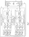
- FIG. 1 is a schematic diagram of a gas turbine 11 and a coordinated air-fuel controller 13 for the gas turbine that includes a cross channel controller operating in a demand space portion of the controller 13.
- the cross-channel controller in Fig. 1 is a steady-state air versus fuel model 15. As will be described further below, the steady-state air versus fuel model 15 provides a relationship between fuel supply for the gas turbine and combustion air supply under steady-state conditions.
- the gas turbine 11 has a plurality of sensors 17 for sensing various conditions associated with the gas turbine.
- Example sensors include a speed sensor for sensing a rotational speed of the gas turbine, a temperature sensor for sensing the temperature of the exhaust gas of the gas turbine, a power level sensor for sensing power supplied by an electrical generator 19 driven by the gas turbine, and a pressure sensor for sensing the gas turbine's compressor pressure. Additional sensors for sensing further conditions associated with the gas turbine can be provided as desired. Estimations of conditions associated with the gas turbine may also take the place of direct sensors.
- the sensors 17 provide feedback signals 21 as inputs to the controller 13.
- the coordinated air-fuel controller 13 can include sub-controllers, such as a cross-channel controller (e.g., the steady-state air versus fuel model 15), a fuel controller 23 and a combustion air controller 25.
- the controller 13 can be an electronic controller and can include one or more processors.
- the controller 13 can include one or more of a microprocessor, a microcontroller, a digital signal processor (DSP), an application specific integrated circuit (ASIC), a field-programmable gate array (FPGA), discrete logic circuitry, or the like.
- the controller 13 can further include memory and may store program instructions that cause the controller to provide the functionality ascribed to it herein.
- the memory may include one or more volatile, non-volatile, magnetic, optical, or electrical media, such as read-only memory (ROM), random access memory (RAM), electrically-erasable programmable ROM (EEPROM), flash memory, or the like.
- the controller 13 can further include one or more analog-to-digital (A/D) converters for processing various analog inputs to the controller.
- A/D analog-to-digital
- the controller 13 includes error calculators 27a-27f.
- the feedback signal 21 from each sensor 17 is input to a respective error calculator 27a-27f for comparison to an associated reference value 29a-29f.
- the output of the error calculators 27a-27f are error signals 31a-31f that are indicative of the difference between the sensed condition and the reference value.
- the sensed rotational speed of the gas turbine can be compared to a speed reference to determine a rotational speed error signal
- the sensed exhaust gas temperature of the gas turbine can be compared with a temperature reference to determine an exhaust temperature error signal.
- the reference values 29a-29f can be boundary values or target values. Boundary values establish limiting operating conditions that should not be passed if possible, such as a maximum temperature or pressure or a minimum speed. Target values establish desired operating conditions, such as a desired speed.
- three error calculators 27a-27c respectively provide error signals 31a-31c as inputs to the fuel controller 23, and three error calculators 27d-27f respectively provide error signals 31d-31f as inputs to the combustion air controller 25. It is to be appreciated that more or fewer than three error calculators can provide error signals to the fuel controller 23 and the combustion air controller 25, and that the fuel controller and combustion air controller need not have the same number of associated error calculators.
- the error signals 31a-31c are processed by the fuel controller 23 in order to generate a fuel control output signal 33.
- the fuel controller 23 provides the fuel control output signal 33 to a fuel control actuator 35 on the gas turbine, to control operations of the fuel control actuator.
- the fuel control actuator 35 responds to the fuel control output signal 33 to control the amount of fuel provided to the combustion chamber of the gas turbine.
- the fuel control actuator 35 can control, for example, a fuel stroke 63 of one or more fuel valves, based on a fuel stroke reference (FSR) signal from the fuel controller 23.
- the fuel controller 23 controls the amount of fuel provided to the combustion area by controlling the operations of the fuel control actuator 35.
- the fuel controller 23 processes the error signals 31a-31c using respective transfer functions K a (s)-K c (s).
- the transfer functions K a (s)-K c (s) can each implement a proportional-integral (PI) control scheme, a proportional-integral-derivative (PID) control scheme, or other control schemes as desired.
- PI proportional-integral
- PID proportional-integral-derivative
- Loop fuel control signals 37a-37c which are output from the transfer functions K a (s)-K c (s), are provided to selection logic 39 of the fuel controller 23. Via the selection logic 39, the fuel controller 23 determines a preliminary fuel control signal 41 based on at least one of the loop fuel control signals 37a-37c.
- the selection logic 39 can provide an algorithm for selecting one of the loop fuel control signals 37a-37c as the preliminary fuel control signal 41.
- the selection logic can prioritize one loop fuel control signal over another in selecting a loop fuel control signal as the preliminary fuel control signal 41, or compare signals to determine which one has a higher/smaller value.
- Example selection logic could be: max(min(37a, 37b), 37c).
- loop fuel control signals 37a and 37b are compared, the smaller of the two (37a, 37b) is further compared to signal 37c, and the larger signal is selected as the preliminary fuel control signal 41.
- the selection logic 39 can compare the loop fuel control signals 37a-37c based on the priority of the boundary conditions and select a loop fuel control signal as the preliminary fuel control signal 41 such that the gas turbine operates within some or all of the boundary conditions. If desired, the selection logic can mathematically combine (e.g., add, average together, etc.) two or more of the loop fuel control signals 37a-37c to obtain the preliminary fuel control signal 41.
- the fuel controller 23 can optionally include an actuator dynamics compensator 43.
- the actuator dynamics compensator 43 processes the preliminary fuel control signal 41 to compensate for response characteristic differences between the fuel control actuator 35 and a combustion air control actuator 45.
- the combustion air control actuator 45 controls the amount of air provided to the combustion chamber of the gas turbine 11.
- the fuel control actuator 35 and the combustion air control actuator 45 can have different response characteristics.
- the fuel control actuator 35 may be able to change the fuel flow rate more quickly than the combustion air control actuator 45 can change the amount of air provided to the combustion chamber.
- the actuator dynamics compensator 43 can delay changing the fuel control output signal 33 by adding a delay to the preliminary fuel control signal 41.
- the actuator dynamics compensator 43 is optional and in embodiments lacking the actuator dynamics compensator, the preliminary fuel control signal 41 is equal or identical to the fuel control output signal 33.
- the combustion air controller 25 generates a combustion air control output signal 47.
- the combustion air controller 25 provides the combustion air control output signal 47 to the combustion air control actuator 45 on the gas turbine 11, to control operations of the combustion air control actuator.
- the combustion air control actuator 45 responds to the combustion air control output signal 47 to control the amount of air provided to the combustion chamber of the gas turbine 11.
- the combustion air control actuator 45 can control, for example, the position (e.g., angle) of inlet guide vanes 65 of the gas turbine 11.
- the combustion air controller 25 controls the amount of air provided to the combustion area by controlling the operations of the combustion air control actuator 45.
- the combustion air controller 25 processes the error signals 31d-31f using respective transfer functions K d (s)-K f (s). Similar to the transfer functions K a (s)-K c (s), the transfer functions K d (s)-K f (s) can implement a desired control scheme, such as a PI or PID control scheme for example. Loop combustion air control signals 37d-37f are output from the transfer functions K d (s)-K f (s) and are provided to selection logic 49 in the combustion air controller 25. Via the selection logic 49, the combustion air controller 25 determines a preliminary combustion air control signal 51.
- the selection logic 49 can provide an algorithm for selecting one of the loop combustion air control signals 37d-37f as the preliminary combustion air control signal 51.
- the selection logic can prioritize one loop combustion air control signal over another in selecting a loop combustion air control signal as the preliminary combustion air control signal 51, or compare signals to determine which one has a higher/smaller value.
- Example selection logic could be: max(min(37d, 37e), 37f).
- the selection logic can be established based on gas turbine operational boundary conditions related to exhaust temperature, compressor pressure ratio, etc.
- the selection logic 49 can compare the loop combustion air control signals 37d-37f based on the priority of the boundary conditions and select a loop combustion air control signal as the preliminary combustion air control signal 51 such that the gas turbine operates within some or all of the boundary conditions. If desired, the selection logic can mathematically combine (e.g., add, average together, etc.) two or more of the loop combustion air control signals 37d-37f to obtain the preliminary combustion air control signal 51.
- the steady-state air versus fuel model 15 receives the preliminary fuel control signal 41 from the fuel controller 23 and calculates an expected steady-state combustion air control signal 53 based on the preliminary fuel control signal 41.
- the steady-state air versus fuel model 15 provides the expected steady-state combustion air control signal 53 to the combustion air controller 25.
- the steady-state air versus fuel model 15 may include automatic adaptation to actual steady-state conditions. In other words, the model may be automatically adjusted to remove any steady-state differences between the combustion air control output signal 47 and the expected steady-state combustion air control signal. This adaptation improves the accuracy of the steady-state air versus fuel model 15.
- the combustion air controller 25 receives the expected steady-state combustion air control signal 53 from the steady-state air versus fuel model 15.
- the combustion air controller 25 determines the combustion air control output signal 47 based on one or both of the preliminary combustion air control signal 51 and the expected steady-state combustion air control signal 53.
- the combustion air controller 25 can include a summing circuit 55 for combining the preliminary combustion air control signal 51 and the expected steady-state combustion air control signal 53 to determine the combustion air control output signal 47.
- the preliminary combustion air control signal 51 and the expected steady-state combustion air control signal 53 can be added together by the summing circuit 55, and the output of the summing circuit 55 is the combustion air control output signal 47.
- the combustion air controller 25 can include an actuator dynamics compensator 57 that processes the output from the summing circuit 55 to compensate for response characteristic differences between the fuel control actuator 35 and the combustion air control actuator 45. If the actuator dynamics compensator 57 is present, then the output of the actuator dynamics compensator 57 is the combustion air control output signal 47, rather than the output of the summing circuit 55 directly.
- summing circuit 55 may be used to combine the preliminary combustion air control signal 51 and the expected steady-state combustion air control signal 53.
- the combination may be done via an algorithm that weights one input over the other, depending on the circumstance.
- the expected steady-state combustion air control signal 53 serves to coordinate operations of the fuel controller 23 and the combustion air controller 25. Such coordination may reduce the likelihood that various adverse conditions of the gas turbine will occur. For example, such coordination may reduce the likelihood of lean blowout, exhaust over temperature and compressor surge.
- the steady-state air versus fuel model 15 uses its model to calculate the expected steady-state combustion air control signal 53 from the preliminary fuel control signal 41.
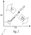
- the air versus fuel model 59 can relate inlet guide vane position (IGV) to fuel stroke reference (FSR).
- the air versus fuel model can directly relate airflow to fuel flow.
- the preliminary fuel control signal 41 directly or indirectly controls the fuel control actuator 35.
- the steady-state air versus fuel model 15 determines and outputs a corresponding expected steady-state combustion air control signal 53 using the air versus fuel model.
- the air versus fuel model can be implemented via an algorithm using a mathematical equation, via a lookup table, or via other known modeling techniques.
- the model 59 can provide a steady-state correspondence between FSR and IGV.
- the steady-state air versus fuel model 15 will output the expected steady-state combustion air control signal 53 to maintain the operation of the gas turbine 11 generally along the steady-state path 61 shown and compensate for fast transient conditions (fast deviations from the from the steady-state path 61).
- Deviations from the steady state path for example too high or too low an IGV value for a given FSR, shown schematically by bent arrows in FIG. 2 , can result in the occurrence of adverse conditions such as lean blow out, exhaust over-temperature and compressor surge.
- the steady-state path 61 is piecewise linear.
- the steady-state path 61 has a horizontal portion in which IGV is constant over a low range of FSR. After the horizontal portion, the steady-state path 61 has a constant positive slope as FSR increases. It is to be appreciated that the steady-state path can have curved portions or a combination of straight and curved portions.
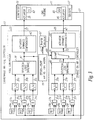
- FIG. 3 is a schematic diagram of a gas turbine 11 and a coordinated air-fuel controller 13.
- the coordinated air-fuel controller 13 shown in FIG. 3 is similar to that shown in FIG. 1 .
- the expected steady-state combustion air control signal 53 is provided to a bounds calculator 67, rather than directly to the combustion air controller 25.
- the bounds calculator 67 determines a variable bias to be applied to the expected steady-state combustion air control signal 53.
- the bounds calculator 67 adds and subtracts the bias to and from the expected steady-state combustion air control signal 53, to output upper and lower bounds for the preliminary combustion air control signal 51.
- the upper and lower bound signals 69 are provided to a clamping portion 71 along with the preliminary combustion air control signal.
- the output 73 of the clamping portion is the preliminary combustion air control signal 51 clamped by the upper and lower bound signal(s) 69.
- the output 73 of the clamping portion equals the preliminary combustion air control signal.
- the output 73 of the clamping portion equals the upper or lower bound, respectively.
- the output 73 of the clamping portion is the combustion air control output signal 47.
- the output 73 of the clamping portion is provided to the actuator dynamics compensator 57, which processes the output 73 to compensate for response characteristic differences between the fuel control actuator 35 and the combustion air control actuator 45.
- the bias used to determine the bounds is variable.
- the bounds calculator 67 analyzes the rate of change of the expected steady-state combustion air control signal 53. If the rate of change of the expected steady-state combustion air control signal 53 is low, a steady-state or near steady-state condition is occurring and the bias is set relatively large. Setting the bias relatively large allows the transfer functions Kd(s)-Kf(s) to dominate in the control of the combustion air control output signal 47, rather than the expected steady-state combustion air control signal 53. If the rate of change of the expected steady-state combustion air control signal 53 is high, a fast transient condition is occurring and the bias is set relatively small or to 0.
- the clamping portion 71 may not be entirely downstream of selection logic 49, but rather integrated into it.
- One or more of the loop combustion air control signals 37d-37f may operate downstream of the clamping portion.
- the input to the clamping portion could be max(37d,37e) while the output of the clamping portion is compared to 37f and the lower of the two becomes the input to the actuator dynamics compensator. This effectively gives the control loop producing 37f higher priority than the upper and lower bound signals 69 coming from the bounds calculator 67.
- various aspects of the present invention provide a model-based coordinated air-fuel control for a gas turbine.
Landscapes
- Engineering & Computer Science (AREA)
- Chemical & Material Sciences (AREA)
- Combustion & Propulsion (AREA)
- Physics & Mathematics (AREA)
- Fluid Mechanics (AREA)
- Mechanical Engineering (AREA)
- General Engineering & Computer Science (AREA)
- Feedback Control In General (AREA)
- Regulation And Control Of Combustion (AREA)
Applications Claiming Priority (1)
| Application Number | Priority Date | Filing Date | Title |
|---|---|---|---|
| US12/780,187 US8171717B2 (en) | 2010-05-14 | 2010-05-14 | Model-based coordinated air-fuel control for a gas turbine |
Publications (3)
| Publication Number | Publication Date |
|---|---|
| EP2386741A2 EP2386741A2 (en) | 2011-11-16 |
| EP2386741A3 EP2386741A3 (en) | 2018-04-18 |
| EP2386741B1 true EP2386741B1 (en) | 2019-08-28 |
Family
ID=44201360
Family Applications (1)
| Application Number | Title | Priority Date | Filing Date |
|---|---|---|---|
| EP11165527.0A Active EP2386741B1 (en) | 2010-05-14 | 2011-05-10 | Model-based coordinated air-fuel control for a gas turbine |
Country Status (4)
| Country | Link |
|---|---|
| US (1) | US8171717B2 (enExample) |
| EP (1) | EP2386741B1 (enExample) |
| JP (1) | JP5194144B2 (enExample) |
| CN (1) | CN102322355B (enExample) |
Families Citing this family (19)
| Publication number | Priority date | Publication date | Assignee | Title |
|---|---|---|---|---|
| US9267443B2 (en) | 2009-05-08 | 2016-02-23 | Gas Turbine Efficiency Sweden Ab | Automated tuning of gas turbine combustion systems |
| US9671797B2 (en) | 2009-05-08 | 2017-06-06 | Gas Turbine Efficiency Sweden Ab | Optimization of gas turbine combustion systems low load performance on simple cycle and heat recovery steam generator applications |
| US8437941B2 (en) | 2009-05-08 | 2013-05-07 | Gas Turbine Efficiency Sweden Ab | Automated tuning of gas turbine combustion systems |
| US9354618B2 (en) | 2009-05-08 | 2016-05-31 | Gas Turbine Efficiency Sweden Ab | Automated tuning of multiple fuel gas turbine combustion systems |
| US8899488B2 (en) | 2011-05-31 | 2014-12-02 | United Technologies Corporation | RFID tag system |
| EP2568145B1 (en) * | 2011-09-08 | 2018-03-21 | Ansaldo Energia IP UK Limited | Gas turbine controller and a method for controlling a gas turbine |
| US20130167549A1 (en) * | 2011-12-29 | 2013-07-04 | Chad M. Holcomb | Compressor guide vane and pilot control for gas turbine engine |
| US8925319B2 (en) * | 2012-08-17 | 2015-01-06 | General Electric Company | Steam flow control system |
| US8720258B2 (en) | 2012-09-28 | 2014-05-13 | United Technologies Corporation | Model based engine inlet condition estimation |
| US9540944B2 (en) | 2012-09-28 | 2017-01-10 | United Technologies Corporation | Real time model based compressor control |
| US20140137538A1 (en) * | 2012-11-16 | 2014-05-22 | United Technologies Corporation | Fast Response Bypass Engine |
| US9850823B2 (en) * | 2013-12-26 | 2017-12-26 | Siemens Aktiengesellschaft | Control system and method for controlling a gas turbine engine during transients |
| US9677476B2 (en) | 2014-02-26 | 2017-06-13 | General Electric Company | Model-based feed forward approach to coordinated air-fuel control on a gas turbine |
| CN104196640B (zh) * | 2014-07-31 | 2017-11-03 | 北京华清燃气轮机与煤气化联合循环工程技术有限公司 | 一种基于重型燃气轮机模型的解耦控制方法和系统 |
| US9819292B2 (en) * | 2014-12-31 | 2017-11-14 | General Electric Company | Systems and methods to respond to grid overfrequency events for a stoichiometric exhaust recirculation gas turbine |
| JP6786233B2 (ja) * | 2016-03-22 | 2020-11-18 | 三菱パワー株式会社 | ガスタービンの特性評価装置及びガスタービンの特性評価方法 |
| US10961921B2 (en) | 2018-09-19 | 2021-03-30 | Pratt & Whitney Canada Corp. | Model-based control system and method for a turboprop engine |
| CN114459054A (zh) * | 2020-11-10 | 2022-05-10 | 中国科学院上海高等研究院 | 在动态过程中保持燃气轮机燃烧稳定的方法、计算机可读介质以及燃机控制系统 |
| KR102536508B1 (ko) * | 2021-03-12 | 2023-05-26 | 한전케이피에스 주식회사 | 응답특성 선형화 해석을 통한 비율 제어기 동기화 튜닝 시스템 및 그 방법 |
Family Cites Families (20)
| Publication number | Priority date | Publication date | Assignee | Title |
|---|---|---|---|---|
| US3797233A (en) * | 1973-06-28 | 1974-03-19 | United Aircraft Corp | Integrated control for a turbopropulsion system |
| US4048964A (en) * | 1975-07-24 | 1977-09-20 | Chrysler Corporation | Fuel metering apparatus and method |
| US4139887A (en) * | 1977-04-28 | 1979-02-13 | United Technologies Corporation | Dynamic compensation for multi-loop controls |
| US4809497A (en) * | 1983-06-15 | 1989-03-07 | Sunstrand Corporation | Gas turbine engine/load compressor power plants |
| US4529887A (en) * | 1983-06-20 | 1985-07-16 | General Electric Company | Rapid power response turbine |
| US4550565A (en) * | 1984-01-16 | 1985-11-05 | Tokyo Shibaura Denki Kabushiki Kaisha | Gas turbine control systems |
| US5133182A (en) * | 1988-09-20 | 1992-07-28 | United Technologies Corporation | Control of low compressor vanes and fuel for a gas turbine engine |
| US4947643A (en) * | 1988-09-20 | 1990-08-14 | United Technologies Corporation | Active geometry control system for gas turbine engines |
| US4928482A (en) * | 1988-09-20 | 1990-05-29 | United Technologies Corporation | Control of high compressor vanes and fuel for a gas turbine engine |
| US4928484A (en) * | 1988-12-20 | 1990-05-29 | Allied-Signal Inc. | Nonlinear multivariable control system |
| US5060469A (en) * | 1989-09-21 | 1991-10-29 | Allied-Signal Inc. | Integrated power unit control apparatus and method |
| JP2954401B2 (ja) * | 1991-08-23 | 1999-09-27 | 株式会社日立製作所 | ガスタービン設備およびその運転方法 |
| US5487265A (en) * | 1994-05-02 | 1996-01-30 | General Electric Company | Gas turbine coordinated fuel-air control method and apparatus therefor |
| EP0890888B1 (de) * | 1997-07-11 | 2003-01-15 | ALSTOM (Switzerland) Ltd | Regelsystem zur Regelung wenigstens einer Variablen eines Prozesses sowie Anwendung eines solchen Regelsystems |
| DE19804026C1 (de) * | 1998-02-02 | 1999-05-06 | Siemens Ag | Verfahren und Regeleinrichtung zur Regelung eines Gasturbosatzes, insbesondere von Gas- und Dampf-Kraftwerken |
| JP3716244B2 (ja) * | 2002-09-19 | 2005-11-16 | 三菱重工業株式会社 | クラッチを備えた一軸コンバインドプラントの運転制御装置及び運転制御方法。 |
| JP2004132255A (ja) * | 2002-10-10 | 2004-04-30 | Mitsubishi Heavy Ind Ltd | 燃焼器制御装置 |
| ITTO20030828A1 (it) * | 2003-10-21 | 2005-04-22 | Ansaldo Energia Spa | Sistema di controllo per turbina a gas. |
| FR2882098B1 (fr) * | 2005-02-17 | 2011-07-15 | Hispano Suiza Sa | Regulation du debit de carburant alimentant un moteur a turbine a gaz |
| US7245040B2 (en) * | 2005-07-15 | 2007-07-17 | Honeywell International, Inc. | System and method for controlling the frequency output of dual-spool turbogenerators under varying load |
-
2010
- 2010-05-14 US US12/780,187 patent/US8171717B2/en not_active Expired - Fee Related
-
2011
- 2011-05-10 EP EP11165527.0A patent/EP2386741B1/en active Active
- 2011-05-12 CN CN201110130362.9A patent/CN102322355B/zh not_active Expired - Fee Related
- 2011-05-12 JP JP2011106890A patent/JP5194144B2/ja not_active Expired - Fee Related
Non-Patent Citations (1)
| Title |
|---|
| None * |
Also Published As
| Publication number | Publication date |
|---|---|
| US20110277482A1 (en) | 2011-11-17 |
| US8171717B2 (en) | 2012-05-08 |
| CN102322355A (zh) | 2012-01-18 |
| EP2386741A3 (en) | 2018-04-18 |
| CN102322355B (zh) | 2015-03-25 |
| JP2011241829A (ja) | 2011-12-01 |
| JP5194144B2 (ja) | 2013-05-08 |
| EP2386741A2 (en) | 2011-11-16 |
Similar Documents
| Publication | Publication Date | Title |
|---|---|---|
| EP2386741B1 (en) | Model-based coordinated air-fuel control for a gas turbine | |
| CA2717613C (en) | Model-based coordinated air-fuel control for a gas turbine | |
| JP6427841B2 (ja) | 燃料制御装置、燃焼器、ガスタービン、制御方法及びプログラム | |
| JP5868671B2 (ja) | 弁制御装置、ガスタービン、及び弁制御方法 | |
| EP1762715B1 (en) | Fuel-flow-rate control device and controlling method for a power generation system | |
| JP5346359B2 (ja) | 燃料制御システムにおける燃焼効率の補償方法 | |
| US9964047B2 (en) | Gas turbine engine optimization control device | |
| JP2015161176A (ja) | 燃料制御装置、燃焼器、ガスタービン、制御方法及びプログラム | |
| WO2016035416A1 (ja) | 制御装置、システム及び制御方法、並びに動力制御装置、ガスタービン及び動力制御方法 | |
| JP6134616B2 (ja) | 2軸ガスタービン | |
| JP5484871B2 (ja) | ガスタービンの制御装置及びその方法並びに発電プラント | |
| JP5595221B2 (ja) | ガスタービンの制御装置、ガスタービン、及びガスタービンの制御方法 | |
| JP2013160154A (ja) | ガスタービン制御装置及び方法並びにプログラム、それを用いた発電プラント | |
| JP6267087B2 (ja) | 動力制御装置、ガスタービン及び動力制御方法 | |
| KR102505388B1 (ko) | 가스 터빈의 제어 장치, 가스 터빈 설비, 가스 터빈의 제어 방법, 및 가스 터빈의 제어 프로그램 | |
| JP6892819B2 (ja) | 制御装置、ガスタービン、コンバインドサイクル発電プラント、制御方法及びプログラム | |
| JP2009197637A (ja) | ガバナフリー制御装置およびガバナフリー制御方法 | |
| JP2016070119A (ja) | ガスタービン設備、その制御装置、及びガスタービン設備の制御方法 | |
| JP5888947B2 (ja) | 弁制御装置、ガスタービン、及び弁制御方法 | |
| CN113841092B (zh) | 用于根据物理参数设定值对涡轮机的实时系统的物理参数进行调节的系统和方法 |
Legal Events
| Date | Code | Title | Description |
|---|---|---|---|
| AK | Designated contracting states |
Kind code of ref document: A2 Designated state(s): AL AT BE BG CH CY CZ DE DK EE ES FI FR GB GR HR HU IE IS IT LI LT LU LV MC MK MT NL NO PL PT RO RS SE SI SK SM TR |
|
| AX | Request for extension of the european patent |
Extension state: BA ME |
|
| PUAI | Public reference made under article 153(3) epc to a published international application that has entered the european phase |
Free format text: ORIGINAL CODE: 0009012 |
|
| PUAL | Search report despatched |
Free format text: ORIGINAL CODE: 0009013 |
|
| AK | Designated contracting states |
Kind code of ref document: A3 Designated state(s): AL AT BE BG CH CY CZ DE DK EE ES FI FR GB GR HR HU IE IS IT LI LT LU LV MC MK MT NL NO PL PT RO RS SE SI SK SM TR |
|
| AX | Request for extension of the european patent |
Extension state: BA ME |
|
| RIC1 | Information provided on ipc code assigned before grant |
Ipc: F02C 9/54 20060101ALI20180309BHEP Ipc: F02C 9/50 20060101AFI20180309BHEP |
|
| STAA | Information on the status of an ep patent application or granted ep patent |
Free format text: STATUS: REQUEST FOR EXAMINATION WAS MADE |
|
| 17P | Request for examination filed |
Effective date: 20181018 |
|
| RBV | Designated contracting states (corrected) |
Designated state(s): AL AT BE BG CH CY CZ DE DK EE ES FI FR GB GR HR HU IE IS IT LI LT LU LV MC MK MT NL NO PL PT RO RS SE SI SK SM TR |
|
| GRAP | Despatch of communication of intention to grant a patent |
Free format text: ORIGINAL CODE: EPIDOSNIGR1 |
|
| STAA | Information on the status of an ep patent application or granted ep patent |
Free format text: STATUS: GRANT OF PATENT IS INTENDED |
|
| RIC1 | Information provided on ipc code assigned before grant |
Ipc: F02C 9/54 20060101ALI20190308BHEP Ipc: F02C 9/50 20060101AFI20190308BHEP |
|
| INTG | Intention to grant announced |
Effective date: 20190402 |
|
| GRAS | Grant fee paid |
Free format text: ORIGINAL CODE: EPIDOSNIGR3 |
|
| GRAJ | Information related to disapproval of communication of intention to grant by the applicant or resumption of examination proceedings by the epo deleted |
Free format text: ORIGINAL CODE: EPIDOSDIGR1 |
|
| GRAL | Information related to payment of fee for publishing/printing deleted |
Free format text: ORIGINAL CODE: EPIDOSDIGR3 |
|
| STAA | Information on the status of an ep patent application or granted ep patent |
Free format text: STATUS: REQUEST FOR EXAMINATION WAS MADE |
|
| GRAR | Information related to intention to grant a patent recorded |
Free format text: ORIGINAL CODE: EPIDOSNIGR71 |
|
| STAA | Information on the status of an ep patent application or granted ep patent |
Free format text: STATUS: GRANT OF PATENT IS INTENDED |
|
| GRAA | (expected) grant |
Free format text: ORIGINAL CODE: 0009210 |
|
| STAA | Information on the status of an ep patent application or granted ep patent |
Free format text: STATUS: THE PATENT HAS BEEN GRANTED |
|
| INTC | Intention to grant announced (deleted) | ||
| INTG | Intention to grant announced |
Effective date: 20190717 |
|
| AK | Designated contracting states |
Kind code of ref document: B1 Designated state(s): AL AT BE BG CH CY CZ DE DK EE ES FI FR GB GR HR HU IE IS IT LI LT LU LV MC MK MT NL NO PL PT RO RS SE SI SK SM TR |
|
| REG | Reference to a national code |
Ref country code: GB Ref legal event code: FG4D |
|
| REG | Reference to a national code |
Ref country code: CH Ref legal event code: EP |
|
| REG | Reference to a national code |
Ref country code: AT Ref legal event code: REF Ref document number: 1172703 Country of ref document: AT Kind code of ref document: T Effective date: 20190915 |
|
| REG | Reference to a national code |
Ref country code: IE Ref legal event code: FG4D |
|
| REG | Reference to a national code |
Ref country code: DE Ref legal event code: R096 Ref document number: 602011061559 Country of ref document: DE |
|
| REG | Reference to a national code |
Ref country code: NL Ref legal event code: MP Effective date: 20190828 |
|
| REG | Reference to a national code |
Ref country code: LT Ref legal event code: MG4D |
|
| REG | Reference to a national code |
Ref country code: DE Ref legal event code: R082 Ref document number: 602011061559 Country of ref document: DE Representative=s name: BRP RENAUD UND PARTNER MBB RECHTSANWAELTE PATE, DE |
|
| PG25 | Lapsed in a contracting state [announced via postgrant information from national office to epo] |
Ref country code: NO Free format text: LAPSE BECAUSE OF FAILURE TO SUBMIT A TRANSLATION OF THE DESCRIPTION OR TO PAY THE FEE WITHIN THE PRESCRIBED TIME-LIMIT Effective date: 20191128 Ref country code: PT Free format text: LAPSE BECAUSE OF FAILURE TO SUBMIT A TRANSLATION OF THE DESCRIPTION OR TO PAY THE FEE WITHIN THE PRESCRIBED TIME-LIMIT Effective date: 20191230 Ref country code: LT Free format text: LAPSE BECAUSE OF FAILURE TO SUBMIT A TRANSLATION OF THE DESCRIPTION OR TO PAY THE FEE WITHIN THE PRESCRIBED TIME-LIMIT Effective date: 20190828 Ref country code: NL Free format text: LAPSE BECAUSE OF FAILURE TO SUBMIT A TRANSLATION OF THE DESCRIPTION OR TO PAY THE FEE WITHIN THE PRESCRIBED TIME-LIMIT Effective date: 20190828 Ref country code: SE Free format text: LAPSE BECAUSE OF FAILURE TO SUBMIT A TRANSLATION OF THE DESCRIPTION OR TO PAY THE FEE WITHIN THE PRESCRIBED TIME-LIMIT Effective date: 20190828 Ref country code: BG Free format text: LAPSE BECAUSE OF FAILURE TO SUBMIT A TRANSLATION OF THE DESCRIPTION OR TO PAY THE FEE WITHIN THE PRESCRIBED TIME-LIMIT Effective date: 20191128 Ref country code: FI Free format text: LAPSE BECAUSE OF FAILURE TO SUBMIT A TRANSLATION OF THE DESCRIPTION OR TO PAY THE FEE WITHIN THE PRESCRIBED TIME-LIMIT Effective date: 20190828 Ref country code: HR Free format text: LAPSE BECAUSE OF FAILURE TO SUBMIT A TRANSLATION OF THE DESCRIPTION OR TO PAY THE FEE WITHIN THE PRESCRIBED TIME-LIMIT Effective date: 20190828 |
|
| PG25 | Lapsed in a contracting state [announced via postgrant information from national office to epo] |
Ref country code: AL Free format text: LAPSE BECAUSE OF FAILURE TO SUBMIT A TRANSLATION OF THE DESCRIPTION OR TO PAY THE FEE WITHIN THE PRESCRIBED TIME-LIMIT Effective date: 20190828 Ref country code: GR Free format text: LAPSE BECAUSE OF FAILURE TO SUBMIT A TRANSLATION OF THE DESCRIPTION OR TO PAY THE FEE WITHIN THE PRESCRIBED TIME-LIMIT Effective date: 20191129 Ref country code: IS Free format text: LAPSE BECAUSE OF FAILURE TO SUBMIT A TRANSLATION OF THE DESCRIPTION OR TO PAY THE FEE WITHIN THE PRESCRIBED TIME-LIMIT Effective date: 20191228 Ref country code: RS Free format text: LAPSE BECAUSE OF FAILURE TO SUBMIT A TRANSLATION OF THE DESCRIPTION OR TO PAY THE FEE WITHIN THE PRESCRIBED TIME-LIMIT Effective date: 20190828 Ref country code: LV Free format text: LAPSE BECAUSE OF FAILURE TO SUBMIT A TRANSLATION OF THE DESCRIPTION OR TO PAY THE FEE WITHIN THE PRESCRIBED TIME-LIMIT Effective date: 20190828 Ref country code: ES Free format text: LAPSE BECAUSE OF FAILURE TO SUBMIT A TRANSLATION OF THE DESCRIPTION OR TO PAY THE FEE WITHIN THE PRESCRIBED TIME-LIMIT Effective date: 20190828 |
|
| REG | Reference to a national code |
Ref country code: AT Ref legal event code: MK05 Ref document number: 1172703 Country of ref document: AT Kind code of ref document: T Effective date: 20190828 |
|
| PG25 | Lapsed in a contracting state [announced via postgrant information from national office to epo] |
Ref country code: TR Free format text: LAPSE BECAUSE OF FAILURE TO SUBMIT A TRANSLATION OF THE DESCRIPTION OR TO PAY THE FEE WITHIN THE PRESCRIBED TIME-LIMIT Effective date: 20190828 |
|
| PG25 | Lapsed in a contracting state [announced via postgrant information from national office to epo] |
Ref country code: IT Free format text: LAPSE BECAUSE OF FAILURE TO SUBMIT A TRANSLATION OF THE DESCRIPTION OR TO PAY THE FEE WITHIN THE PRESCRIBED TIME-LIMIT Effective date: 20190828 Ref country code: AT Free format text: LAPSE BECAUSE OF FAILURE TO SUBMIT A TRANSLATION OF THE DESCRIPTION OR TO PAY THE FEE WITHIN THE PRESCRIBED TIME-LIMIT Effective date: 20190828 Ref country code: DK Free format text: LAPSE BECAUSE OF FAILURE TO SUBMIT A TRANSLATION OF THE DESCRIPTION OR TO PAY THE FEE WITHIN THE PRESCRIBED TIME-LIMIT Effective date: 20190828 Ref country code: PL Free format text: LAPSE BECAUSE OF FAILURE TO SUBMIT A TRANSLATION OF THE DESCRIPTION OR TO PAY THE FEE WITHIN THE PRESCRIBED TIME-LIMIT Effective date: 20190828 Ref country code: EE Free format text: LAPSE BECAUSE OF FAILURE TO SUBMIT A TRANSLATION OF THE DESCRIPTION OR TO PAY THE FEE WITHIN THE PRESCRIBED TIME-LIMIT Effective date: 20190828 Ref country code: RO Free format text: LAPSE BECAUSE OF FAILURE TO SUBMIT A TRANSLATION OF THE DESCRIPTION OR TO PAY THE FEE WITHIN THE PRESCRIBED TIME-LIMIT Effective date: 20190828 |
|
| PG25 | Lapsed in a contracting state [announced via postgrant information from national office to epo] |
Ref country code: CZ Free format text: LAPSE BECAUSE OF FAILURE TO SUBMIT A TRANSLATION OF THE DESCRIPTION OR TO PAY THE FEE WITHIN THE PRESCRIBED TIME-LIMIT Effective date: 20190828 Ref country code: SM Free format text: LAPSE BECAUSE OF FAILURE TO SUBMIT A TRANSLATION OF THE DESCRIPTION OR TO PAY THE FEE WITHIN THE PRESCRIBED TIME-LIMIT Effective date: 20190828 Ref country code: SK Free format text: LAPSE BECAUSE OF FAILURE TO SUBMIT A TRANSLATION OF THE DESCRIPTION OR TO PAY THE FEE WITHIN THE PRESCRIBED TIME-LIMIT Effective date: 20190828 Ref country code: IS Free format text: LAPSE BECAUSE OF FAILURE TO SUBMIT A TRANSLATION OF THE DESCRIPTION OR TO PAY THE FEE WITHIN THE PRESCRIBED TIME-LIMIT Effective date: 20200224 |
|
| REG | Reference to a national code |
Ref country code: DE Ref legal event code: R097 Ref document number: 602011061559 Country of ref document: DE |
|
| PLBE | No opposition filed within time limit |
Free format text: ORIGINAL CODE: 0009261 |
|
| STAA | Information on the status of an ep patent application or granted ep patent |
Free format text: STATUS: NO OPPOSITION FILED WITHIN TIME LIMIT |
|
| PG2D | Information on lapse in contracting state deleted |
Ref country code: IS |
|
| 26N | No opposition filed |
Effective date: 20200603 |
|
| PG25 | Lapsed in a contracting state [announced via postgrant information from national office to epo] |
Ref country code: SI Free format text: LAPSE BECAUSE OF FAILURE TO SUBMIT A TRANSLATION OF THE DESCRIPTION OR TO PAY THE FEE WITHIN THE PRESCRIBED TIME-LIMIT Effective date: 20190828 |
|
| PG25 | Lapsed in a contracting state [announced via postgrant information from national office to epo] |
Ref country code: MC Free format text: LAPSE BECAUSE OF FAILURE TO SUBMIT A TRANSLATION OF THE DESCRIPTION OR TO PAY THE FEE WITHIN THE PRESCRIBED TIME-LIMIT Effective date: 20190828 Ref country code: LI Free format text: LAPSE BECAUSE OF NON-PAYMENT OF DUE FEES Effective date: 20200531 Ref country code: CH Free format text: LAPSE BECAUSE OF NON-PAYMENT OF DUE FEES Effective date: 20200531 |
|
| REG | Reference to a national code |
Ref country code: BE Ref legal event code: MM Effective date: 20200531 |
|
| PG25 | Lapsed in a contracting state [announced via postgrant information from national office to epo] |
Ref country code: LU Free format text: LAPSE BECAUSE OF NON-PAYMENT OF DUE FEES Effective date: 20200510 |
|
| PG25 | Lapsed in a contracting state [announced via postgrant information from national office to epo] |
Ref country code: IE Free format text: LAPSE BECAUSE OF NON-PAYMENT OF DUE FEES Effective date: 20200510 |
|
| PG25 | Lapsed in a contracting state [announced via postgrant information from national office to epo] |
Ref country code: BE Free format text: LAPSE BECAUSE OF NON-PAYMENT OF DUE FEES Effective date: 20200531 |
|
| PGFP | Annual fee paid to national office [announced via postgrant information from national office to epo] |
Ref country code: DE Payment date: 20210421 Year of fee payment: 11 Ref country code: FR Payment date: 20210421 Year of fee payment: 11 |
|
| PGFP | Annual fee paid to national office [announced via postgrant information from national office to epo] |
Ref country code: GB Payment date: 20210422 Year of fee payment: 11 |
|
| PG25 | Lapsed in a contracting state [announced via postgrant information from national office to epo] |
Ref country code: MT Free format text: LAPSE BECAUSE OF FAILURE TO SUBMIT A TRANSLATION OF THE DESCRIPTION OR TO PAY THE FEE WITHIN THE PRESCRIBED TIME-LIMIT Effective date: 20190828 Ref country code: CY Free format text: LAPSE BECAUSE OF FAILURE TO SUBMIT A TRANSLATION OF THE DESCRIPTION OR TO PAY THE FEE WITHIN THE PRESCRIBED TIME-LIMIT Effective date: 20190828 |
|
| PG25 | Lapsed in a contracting state [announced via postgrant information from national office to epo] |
Ref country code: MK Free format text: LAPSE BECAUSE OF FAILURE TO SUBMIT A TRANSLATION OF THE DESCRIPTION OR TO PAY THE FEE WITHIN THE PRESCRIBED TIME-LIMIT Effective date: 20190828 |
|
| REG | Reference to a national code |
Ref country code: DE Ref legal event code: R119 Ref document number: 602011061559 Country of ref document: DE |
|
| GBPC | Gb: european patent ceased through non-payment of renewal fee |
Effective date: 20220510 |
|
| PG25 | Lapsed in a contracting state [announced via postgrant information from national office to epo] |
Ref country code: FR Free format text: LAPSE BECAUSE OF NON-PAYMENT OF DUE FEES Effective date: 20220531 |
|
| PG25 | Lapsed in a contracting state [announced via postgrant information from national office to epo] |
Ref country code: GB Free format text: LAPSE BECAUSE OF NON-PAYMENT OF DUE FEES Effective date: 20220510 Ref country code: DE Free format text: LAPSE BECAUSE OF NON-PAYMENT OF DUE FEES Effective date: 20221201 |