EP2386349A1 - Spacing member, membrane element, and immersed membrane separation device - Google Patents
Spacing member, membrane element, and immersed membrane separation device Download PDFInfo
- Publication number
- EP2386349A1 EP2386349A1 EP09837448A EP09837448A EP2386349A1 EP 2386349 A1 EP2386349 A1 EP 2386349A1 EP 09837448 A EP09837448 A EP 09837448A EP 09837448 A EP09837448 A EP 09837448A EP 2386349 A1 EP2386349 A1 EP 2386349A1
- Authority
- EP
- European Patent Office
- Prior art keywords
- membrane
- spacing
- elements
- spacing member
- membrane elements
- Prior art date
- Legal status (The legal status is an assumption and is not a legal conclusion. Google has not performed a legal analysis and makes no representation as to the accuracy of the status listed.)
- Withdrawn
Links
Images










Classifications
-
- B—PERFORMING OPERATIONS; TRANSPORTING
- B01—PHYSICAL OR CHEMICAL PROCESSES OR APPARATUS IN GENERAL
- B01D—SEPARATION
- B01D61/00—Processes of separation using semi-permeable membranes, e.g. dialysis, osmosis or ultrafiltration; Apparatus, accessories or auxiliary operations specially adapted therefor
- B01D61/14—Ultrafiltration; Microfiltration
- B01D61/18—Apparatus therefor
-
- B—PERFORMING OPERATIONS; TRANSPORTING
- B01—PHYSICAL OR CHEMICAL PROCESSES OR APPARATUS IN GENERAL
- B01D—SEPARATION
- B01D63/00—Apparatus in general for separation processes using semi-permeable membranes
- B01D63/08—Flat membrane modules
- B01D63/082—Flat membrane modules comprising a stack of flat membranes
- B01D63/0821—Membrane plate arrangements for submerged operation
-
- C—CHEMISTRY; METALLURGY
- C02—TREATMENT OF WATER, WASTE WATER, SEWAGE, OR SLUDGE
- C02F—TREATMENT OF WATER, WASTE WATER, SEWAGE, OR SLUDGE
- C02F3/00—Biological treatment of water, waste water, or sewage
- C02F3/02—Aerobic processes
- C02F3/12—Activated sludge processes
- C02F3/1236—Particular type of activated sludge installations
- C02F3/1268—Membrane bioreactor systems
- C02F3/1273—Submerged membrane bioreactors
-
- B—PERFORMING OPERATIONS; TRANSPORTING
- B01—PHYSICAL OR CHEMICAL PROCESSES OR APPARATUS IN GENERAL
- B01D—SEPARATION
- B01D2313/00—Details relating to membrane modules or apparatus
- B01D2313/14—Specific spacers
- B01D2313/143—Specific spacers on the feed side
-
- B—PERFORMING OPERATIONS; TRANSPORTING
- B01—PHYSICAL OR CHEMICAL PROCESSES OR APPARATUS IN GENERAL
- B01D—SEPARATION
- B01D2315/00—Details relating to the membrane module operation
- B01D2315/06—Submerged-type; Immersion type
-
- C—CHEMISTRY; METALLURGY
- C02—TREATMENT OF WATER, WASTE WATER, SEWAGE, OR SLUDGE
- C02F—TREATMENT OF WATER, WASTE WATER, SEWAGE, OR SLUDGE
- C02F2201/00—Apparatus for treatment of water, waste water or sewage
- C02F2201/002—Construction details of the apparatus
-
- Y—GENERAL TAGGING OF NEW TECHNOLOGICAL DEVELOPMENTS; GENERAL TAGGING OF CROSS-SECTIONAL TECHNOLOGIES SPANNING OVER SEVERAL SECTIONS OF THE IPC; TECHNICAL SUBJECTS COVERED BY FORMER USPC CROSS-REFERENCE ART COLLECTIONS [XRACs] AND DIGESTS
- Y02—TECHNOLOGIES OR APPLICATIONS FOR MITIGATION OR ADAPTATION AGAINST CLIMATE CHANGE
- Y02W—CLIMATE CHANGE MITIGATION TECHNOLOGIES RELATED TO WASTEWATER TREATMENT OR WASTE MANAGEMENT
- Y02W10/00—Technologies for wastewater treatment
- Y02W10/10—Biological treatment of water, waste water, or sewage
Definitions
- the present invention relates to spacing members that keep spacing between membrane elements for filtering a liquid to be treated, membrane elements provided with the spacing members, and submerged membrane separation device.
Landscapes
- Chemical & Material Sciences (AREA)
- Engineering & Computer Science (AREA)
- Water Supply & Treatment (AREA)
- Chemical Kinetics & Catalysis (AREA)
- Life Sciences & Earth Sciences (AREA)
- Biodiversity & Conservation Biology (AREA)
- Microbiology (AREA)
- Hydrology & Water Resources (AREA)
- Environmental & Geological Engineering (AREA)
- Organic Chemistry (AREA)
- Separation Using Semi-Permeable Membranes (AREA)
Abstract
Description
- The present invention relates to spacing members that keep spacing between membrane elements for filtering a liquid to be treated, membrane elements provided with the spacing members, and submerged membrane separation device.
- In the related art, as shown in
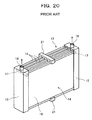
FIGS. 19 and20 , a submerged membrane separation device is installed in a treatment tank and submerged inwater 12 to be treated, e.g., sewage. A submergedmembrane separation device 13 includesmultiple membrane elements 14 and multiple membrane joining/fixing members 15. Themembrane elements 14 are arranged at predetermined spacing in the thickness direction. The membrane joining/fixing members 15 are disposed on both ends of themembrane elements 14. The ends of themembrane elements 14 are joined and connected by the membrane joining/fixing members 15. - The
membrane elements 14 are flat plates or sheets, each havingfiltration membranes 16 on the front and back sides. The membrane joining/fixing member 15 has awater collecting pipe 17 for collecting water permeated through thefiltration membranes 16. On the upper end of thewater collecting pipe 17, asuction pipe 18 is formed. Further, anair diffuser 19 is provided below themembrane elements 14. - Pressures in the
membrane elements 14 are reduced from thesuction pipes 18 by, e.g., a suction pump to enable thefiltration membranes 16 to capture solid contents such as sludge in thewater 12 to be treated. Subsequently, water having permeated through thefiltration membranes 16 and flown into themembrane elements 14 is collected as treated water in thewater collecting pipe 17, and then the treated water is drained out of thewater collecting pipe 17 through thesuction pipe 18. - At this point, air sent from the
air diffuser 19 produces an air-lift effect to generate upwardflows 20 in a gas-liquid phase between themembrane elements 14. The upward flows 20 clean the membrane surfaces of themembrane elements 14. - The submerged
membrane separation device 13 further includesspacing members 21 that keep spacing between thefiltration membranes 16 between theadjacent membrane elements 14. As shown inFIGS. 20 and21 , thespacing members 21 are comb-likemembers having teeth 22 and are respectively attached to the upper and lower ends of themembrane elements 14. Theteeth 22 of theupper spacing member 21 are inserted between the upper ends of themembrane elements 14 and theteeth 22 of thelower spacing member 21 are inserted between the lower ends of themembrane elements 14. - With this configuration, the
upper spacing member 21 keeps spacing 23a between the upper ends of themembrane elements 14 at predetermined spacing and thelower spacing member 21 keeps spacing 23b between the lower ends of themembrane elements 14 at the predetermined spacing. - The submerged
membrane separation device 13 including thespacing members 21 is described in, e.g.,Patent Literature 1. -
- Patent Literature 1: Japanese Patent Laid-Open No.
2000-237551 - In the system of the related art, however, spacing between the
filtration membranes 16 between theadjacent membrane elements 14 is kept at the predetermined spacing only on the upper and lower ends of theadjacent membrane elements 14. The predetermined spacing is not always kept over themembrane elements 14, that is, from the upper ends to the lower ends of themembrane elements 14. For example, in the case where a thickness T of themembrane element 14 is reduced to increase the number ofmembrane elements 14 attached per unit area, themembrane elements 14 are reduced in stiffness. As indicated by virtual lines inFIG. 21 , themembrane elements 14 are bent (deformed) by a force of, e.g., the upward flows 20, so that spacing 23c at a central part between the upper and lower ends of themembrane element 14 cannot be kept at the predetermined spacing. Consequently, at the central part not kept at the predetermined spacing, the membrane surface cleaning effect of theupward flows 20 is lessened to cause buildup of solid contents such as sludge in thewater 12 to be treated, leading to clogging between the membranes. This problem occurs also in the case where themembrane elements 14 are increased in size. - As shown in
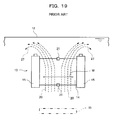
FIG. 19 , theupward flows 20 used as membrane surface cleaning streams for cleaning the membrane surfaces of thefiltration membranes 16 turn downward as downward flows 27 outside the membrane joining/fixingmembers 15 after passing between themembrane elements 14. Thus the upward flows 20 concentrate near the membrane joining/fixingmembers 15 and decrease at a central part in width direction W of themembrane element 14, so that the membrane surface cleaning effect is insufficient at the central part in the width direction W of themembrane element 14. - An object of the present invention is to provide a spacing member, a membrane element, and a submerged membrane separation device which can keep predetermined spacing between filtration membranes between adjacent membrane elements in the direction of a membrane surface cleaning stream, and obtain a sufficient membrane surface cleaning effect substantially uniformly in the width direction of the membrane element.
- In order to attain the object, a spacing member according to a first aspect of the present invention is a spacing member keeping spacing between filtration membranes between membrane elements arranged with the filtration membranes opposed to each other, the membrane element having the filtration membranes on the flat part of the membrane element, the spacing member including at least one spacer section keeping the spacing between the filtration membranes between the membrane elements in the direction of a membrane surface cleaning stream flowing along the filtration membrane surface of the membrane element.
- With this configuration, the spacer section of the spacing member is disposed between the membrane elements, thereby keeping the spacing between the filtration membranes between the membrane elements (that is, spacing between the opposed filtration membranes of the membrane elements) across the membrane element at predetermined spacing. At this point, the spacer section is disposed between the membrane elements in the direction of the membrane surface cleaning stream of the membrane element, thereby keeping the spacing between the filtration membranes between the membrane elements at the predetermined spacing in the direction of the membrane surface cleaning stream of the membrane element. The predetermined spacing is, e.g., regular spacing set in design and so on.
- The spacing member according to a second aspect of the present invention, wherein the at least one spacer section is disposed between the membrane elements over the height of the membrane element.
- The spacing member according to a third aspect of the present invention, wherein the at least one spacer section is detachably attached to the membrane element.
- This configuration facilitates fabrication and maintenance of a membrane module.
- The spacing member according to a fourth aspect of the present invention, wherein the at least one spacer section includes multiple spacer secti.ons, each being disposed between the different membrane elements.
- With this configuration, the spacer sections of the spacing member are simultaneously inserted or removed between the membrane elements, facilitating fabrication and maintenance of the membrane module.
- The spacing member according to a fifth aspect of the present invention includes a fastening device for fastening the at least one spacer section on the membrane element.
- With this configuration, the spacer section is attached to the membrane element and is fixed thereon by the fastening device, thereby preventing the spacing member from accidentally falling off the membrane element.
- The spacing member according to a sixth aspect of the present invention, wherein the at least one spacer section is integrally formed with the membrane element.
- A membrane clement according to a seventh aspect of the present invention includes filtration membranes, wherein the spacing member according to any one of the first to sixth aspects of the present invention keeps the spacing between the filtration membranes between the membrane elements.
- A submerged membrane separation device according to an eighth aspect of the present invention, including the membrane elements of the seventh aspect, the membrane elements being submerged for membrane filtration in a liquid to be treated,
the submerged membrane separation device further including an air diffuser below the membrane elements, the air diffuser diffusing air to generate upward flows as membrane surface cleaning streams, the upward flows cleaning the filtration membrane surface. - With this configuration, the air diffusion of the air diffuser generates upward flows in a gas-liquid phase between the membrane elements by an air-lift effect and the upward flows clean the membrane surfaces of the membrane elements. In this case, the spacing members divide the area of the upward flows into multiple sections in the width direction of the membrane element. Thus the upward flows acting as the membrane surface cleaning streams for cleaning the filtration membrane surfaces are generated along the membrane surfaces of the membrane elements in the sections separated by the spacing members and the concentrated flows are dispersed to generate substantially uniform flows in the width direction of the membrane element. Consequently, a membrane surface cleaning effect can be sufficiently obtained in the width direction of the membrane element.
- As has been discussed, according to the present invention, the spacer sections of a spacing member are provided across a membrane element in the direction of a membrane surface cleaning stream, thereby keeping spacing between filtration membranes between membrane elements at predetermined spacing in the direction of the membrane surface cleaning stream.
- Further, upward flows used as membrane surface cleaning streams are generated along the membrane surfaces of the membrane elements in the sections separated by the spacing members, so that the concentration of upward flows in the width direction of the membrane element can be suppressed and a membrane surface cleaning effect can be sufficiently obtained in the width direction of the membrane element.
-
- [
FIG. 1] FIG. 1 is a front view showing a submerged membrane separation device according to a first embodiment of the present invention. - [
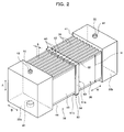
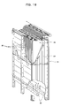
FIG. 2] FIG. 2 is a perspective view showing a membrane module of the submerged membrane separation device with spacing members attached to the membrane module, according to the first embodiment of the present invention. - [
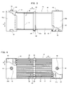
FIG. 3] FIG. 3 is a partially cut front view showing the membrane module having the attached spacing members, according to the first embodiment of the present invention. - [
FIG. 4] FIG. 4 is a partially cut plan view showing the membrane module having the attached spacing members, according to the first embodiment of the present invention. - [
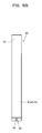
FIG. 5A] FIG. 5A is a side view showing the spacing member attached to the membrane module, according to the first embodiment of the present invention. - [
FIG. 5B] FIG. 5B is a front view showing the spacing member attached to the membrane module, according to the first embodiment of the present invention. - [
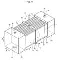
FIG. 6] FIG. 6 is a perspective view showing a membrane module having attached spacing members according to a second embodiment of the present invention. - [
FIG. 7A] FIG. 7A is a perspective view showing the spacing member attached to the membrane module, according to the second embodiment of the present invention. - [
FIG. 7B] FIG. 7B is a side view showing the spacing member attached to the membrane module, according to the second embodiment of the present invention. - [
FIG. 8] FIG. 8 is a perspective view showing a membrane module having attached spacing members according to a third embodiment of the present invention. - [
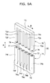
FIG. 9A] FIG. 9A is an exploded perspective view showing the spacing member attached to the membrane module, according to the third embodiment of the present invention. - [
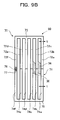
FIG. 9B] FIG. 9B is an assembly side view showing the spacing member attached to the membrane module, according to the third embodiment of the present invention. - [
FIG. 10] FIG. 10 is a perspective view showing a membrane module having attached spacing members according to a fourth embodiment of the present invention. - [
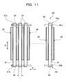
FIG. 11] FIG. 11 is a partially omitted side view showing the spacing member attached to the membrane module, according to the fourth embodiment of the present invention. - [
FIG. 12] FIG. 12 is a perspective view showing a membrane module according to a fifth embodiment of the present invention. - [
FIG. 13] FIG. 13 is a plan view showing a membrane element of the membrane module, according to the fifth embodiment of the present invention. - [
FIG. 14] FIG. 14 is a plan view showing a membrane element of a membrane module according to a sixth embodiment of the present invention. - [
FIG. 15] FIG. 15 is a front view showing a submerged membrane separation device according to a seventh embodiment of the present invention. - [
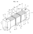
FIG. 16] FIG. 16 is a perspective view showing a membrane module according to an eighth embodiment of the present invention. - [
FIG. 17A] FIG. 17A is an exploded perspective view showing a membrane element of a membrane module according to a ninth embodiment of the present invention, the membrane element having a loop filtration membrane. - [
FIG. 17B] FIG. 17B is an exploded perspective view showing the membrane element of the membrane module according to the ninth embodiment of the present invention, the membrane element having a loop filtration membrane divided in two. - [
FIG. 18] FIG. 18 is a partially cut perspective view showing a submerged membrane separation device having a different configuration from the submerged membrane separation devices according to the first to ninth embodiments of the present invention. - [
FIG. 19] FIG. 19 is a front view showing a submerged membrane separation device having attached spacing members according to the related art. - [
FIG. 20] FIG. 20 is a perspective view showing the submerged membrane separation device having the attached spacing members, according to the related art. - [
FIG. 21] FIG. 21 . is a side view showing the spacing members and membrane elements, according to the related art. - Referring to
FIGS. 1 to 5A and 5B , a first embodiment of the present invention will be described below. - As shown in
FIG. 1 ,reference numeral 31 denotes a submerged membrane separation device for membrane filtration. The submergedmembrane separation device 31 is submerged in a liquid 33 to be treated, e.g., organic waste water and is installed in atreatment tank 32. The submergedmembrane separation device 31 includesmultiple membrane modules 34 stacked in vertical direction A. - As shown in
FIGS. 2 to 4 , themembrane module 34 includes a pair ofwater collecting cases multiple membrane elements 36 that are arranged and fixed between thewater collecting cases water collecting cases water collecting space 43. - The
membrane elements 36 are arrange in parallel at predetermined spacing S in thickness direction B. Themembrane element 36 includes afiltration plate 44 that is a rectangular plate andfiltration membranes 45 that are flat membranes respectively attached to flat parts on the front and back sides of thefiltration plate 44 by, e.g., welding. On each surface of thefiltration plate 44, a permeated water passage is horizontally formed so as to communicate with thewater collecting spaces 43. The permeated water passage is covered with thefiltration membrane 45. - The
water collecting cases inner plate 42 made of adhesive resin. As shown inFIG. 4 , the lateral side edges of themembrane element 36 are inserted into thewater collecting spaces 43 through theinner plates 42. Thus themembrane elements 36 are fixed to thewater collecting cases water collecting cases filtration membranes 45 opposed to each other. - On each of the upper ends of the
water collecting cases portion 48 is provided so as to project upward. On each of the undersides of thewater collecting cases hole 49 is provided. In the projectingportion 48, a communicatinghole 50 is formed that communicates with the outer surface of the upper end and thewater collecting space 43. Theholes 49 respectively communicate with the outer surfaces of the undersides of thewater collecting cases water collecting spaces 43. The projectingportion 48 of thelower membrane module 34 is detachably fit into thehole 49 of theupper membrane module 34 in the vertical direction A. - As shown in
FIG. 1 , thewater collecting space 43 of thelower membrane module 34 communicates with thewater collecting space 43 of theupper membrane module 34 through the communicatinghole 50 of the projectingportion 48. Further,water collecting pipes 51 are respectively provided on the right and left sides of thetop membrane module 34. The projectingportion 48 of thetop membrane module 34 and thewater collecting pipe 51 are connected to each other via a connectingpipe 52. Thewater collecting pipe 51 is connected to a permeated water collecting pipe that includes a suction pump. - Below the
membrane elements 36 of thelowest membrane module 34, anair diffuser 53 is provided for diffusing air. Thelowest membrane module 34 is supported on a diffusingcase 54 that guides air from theair diffuser 53 to theupper membrane module 34. Thehole 49 of thelowest membrane module 34 is closed. - The
air diffuser 53 includes a horizontalmain pipe 55 that receives air from an air supplier (e.g., a blower) andmultiple branch pipes 56 orthogonal to themain pipe 55. Thebranch pipe 56 includesmultiple air outlets 57 for diffusing air. - The
membrane module 34 includes multipledetachable spacing members 60, each keeping the spacing S between thefiltration membranes 45 between theadjacent membrane elements 36. The spacing S between thefiltration membranes 45 between theadjacent membrane elements 36 is spacing between thefiltration membranes 45 of the opposedmembrane elements 36. As shown inFIGS. 5A and5B , the spacingmember 60 has a pair ofspacer sections portion 62 that connects the upper ends of thespacer sections fastening device 63 that fastens the spacingmember 60 on themembrane element 36. - The
spacer sections membrane elements 36 and are interposed between themembrane elements 36 over a height H of themembrane element 36. The lower ends of thespacer sections membrane element 36. - The
fastening device 63 includes abolt 64 attached across the lower ends of thespacer sections nut 65 screwed onto thebolt 64. Thebolt 64 is removably inserted intobolt holes spacer sections membrane element 36. - The effect of the configuration will be described below.
- The
spacing members 60 are each attached from above themembrane element 36 to insert themembrane element 36 between thespacer sections spacing members 60 are arranged in a straight line along the thickness direction B of themembrane element 36. Thus thespacer section 61a of one of theadjacent spacing members 60 and thespacer section 61b of theother spacing member 60 are inserted between themembrane elements 36 and are disposed therebetween over the height H of themembrane element 36, thereby keeping the spacing S between thefiltration membranes 45 between theadjacent membrane elements 36 at the predetermined spacing over the height H (an example of the direction of the membrane surface cleaning stream). Thespacer sections membrane elements 36. - As has been discussed, the
spacer sections member 60 are inserted between themembrane elements 36, thebolt 64 is inserted into the bolt holes 66a and 66b, and thenut 65 is screwed onto thebolt 64, so that thebolt 64 below themembrane element 36 is orthogonal to themembrane element 36. The spacingmember 60 is fixed thus on themembrane element 36 in the vertical direction A. - After the
spacing members 60 are attached thus to themembrane modules 34, themembrane modules 34 are stacked to complete themembrane separation device 31 as shown inFIG. 1 and are submerged in the liquid 33 to be treated in thetreatment tank 32. After that, the suction bump is driven to supply air from the air supplier to theair diffuser 53, starting a filtering operation. - Thus pressures in the
membrane elements 36 are reduced and solid contents such as sludge in the liquid 33 to be treated are captured by thefiltration membranes 45 of themembrane elements 36. Permeated water through thefiltration membranes 45 flows into the permeated water passages of themembrane elements 36, and then the permeated water flows into thewater collecting spaces 43 of thewater collecting cases - The projecting
portions 48 of thelower membrane module 34 are fit into theholes 49 of theupper membrane module 34, and thewater collecting spaces 43 of thelower membrane module 34 communicate with thewater collecting spaces 43 of theupper membrane module 34 through the communicatingholes 50 of the projectingportions 48. Thus the permeated water (that is, treated water) collected in thewater collecting spaces 43 of thelower membrane module 34 passes through the communicatingholes 50, flows into thewater collecting spaces 43 of theupper membrane module 34 from thewater collecting spaces 43 of thelower membrane module 34, flows into thewater collecting pipes 51 from thewater collecting spaces 43 of thetop membrane module 34 through the connectingpipes 52, and then flows into the permeated water collecting pipes from thewater collecting pipes 51. After that, that water is collected out of thetreatment tank 32. - Further, air from the
air outlets 57 of theair diffuser 53 floats up as air bubbles, generating upward flows 58 (an example of the membrane surface cleaning stream) in a gas-liquid phase between themembrane elements 36. The upward flows 58 along the surfaces of thefiltration membranes 45 of themembrane elements 36 clean the membrane surfaces of themembrane elements 36, thereby preventing buildup of solid contents such as sludge on the membrane surfaces of themembrane elements 36. At this point, the upward flows 58 apply an upward force to thespacing members 60 but thebolts 64 of thefastening devices 63 come into contact with the undersides of themembrane elements 36, thereby preventing thespacing members 60 from accidentally falling off themembrane elements 36 upward. - Moreover, it is possible to prevent the upper or lower parts of the
membrane elements 36 from cracking or wearing due to stress concentration. - Referring to
FIGS. 6 ,7A , and7B , a second embodiment of the present invention will be described below. - In the first embodiment, the spacing
member 60 includes the pair of spacer sections, that is, the twospacer sections FIGS. 7A and7B , a spacingmember 60 is shaped like a comb having at least twospacer sections 61a to 61f. The upper ends of thespacer sections 61a to 61f are connected by a connectingportion 62 extended in thickness direction B of amembrane element 36. - A
fastening device 63 includes abolt 64 attached across the lower ends of thespacer sections 61a to 61f, and anut 65 screwed onto thebolt 64. Thebolt 64 is removably inserted intobolt holes 66a to 66f formed on the lower ends of thespacer section 61a to 61f, in the thickness direction B of themembrane element 36. - The effect of the configuration will be described below.
- As shown in
FIG. 6 , thespacer sections 61a to 61f of thespacing members 60 are inserted between thedifferent membrane elements 36 from above. Thus spacing S betweenfiltration membranes 45 between themembrane elements 36 is kept at predetermined spacing over a height H of themembrane element 36. Thespacer sections 61a to 61f have a thickness t that is equal to the predetermined spacing S between themembrane elements 36. - The
spacer sections 61a to 61f are simultaneously inserted or removed between themembrane elements 36, facilitating fabrication and maintenance of amembrane module 34. - The
bolt 64 is inserted into the bolt holes 66a to 66f and thenut 65 is screwed onto thebolt 64, so that thebolt 64 is orthogonal to themembrane elements 36 below themembrane elements 36. The spacingmember 60 is fastened thus on themembrane element 36 in vertical direction A. - In the second embodiment, as shown in
FIGS. 7A and7B , the spacingmember 60 includes the sixspacer sections 61a to 61f. The number of spacer sections is not limited to six as long as at least two spacer sections are provided. - Referring to
FIGS. 8 ,9A , and9B , a third embodiment of the present invention will be described below. - A spacing
member 60 is divided into an upper (one) spacingmember 70 and a lower (other) spacingmember 71. Theupper spacing member 70 is shaped like a comb having multipleupper spacer sections 72a to 72f. The upper ends of theupper spacer sections 72a to 72f are connected by an upper connectingportion 73 extended in thickness direction B of amembrane element 36. on the respective lower ends of theupper spacer sections 72a to 72f, projectingportions 76 are formed so as to project downward. - The
lower spacing member 71 is shaped like a comb having multiplelower spacer sections 74a to 74f, like theupper spacing member 70. The lower ends of thelower spacer sections 74a to 74f are connected by a lower connectingportion 75. On the respective upper ends of thelower spacer sections 74a to 74f, recessedportions 77 are formed. The projectingportions 76 are removably fit into the recessedportions 77 in vertical direction A. - The effect of the configuration will be described below.
- The
spacer sections 74a to 74f of thelower spacing member 71 are inserted between themembrane elements 36 from below and thespacer sections 72a to 72f of theupper spacing member 70 are inserted between themembrane elements 36 from above, so that the projectingportions 76 are fit into the respective recessedportions 77. Theupper spacing member 70 and thelower spacing member 71 are joined to each other to constitute the spacingmember 60, which keeps spacing S betweenfiltration membranes 45 between themembrane elements 36 at predetermined spacing over a height H of themembrane element 36. Thespacer sections 72a to 72f and 74a to 74f have a thickness t that is equal to the predetermined spacing S between themembrane elements 36. - In the third embodiment, as shown in
FIGS. 9A and9B , theupper spacing member 70 includes the sixupper spacer sections 72a to 72f. The number of upper spacer sections is not limited to six as long as at least two upper spacer sections are provided. Similarly, thelower spacing member 71 includes the sixlower spacer sections 74a to 74f and the number of lower spacer sections is not limited to six as long as at least two lower spacer sections are provided. - Referring to
FIGS. 10 and11 , a fourth embodiment of the present invention will be described below. - A spacing
member 60 includes:multiple spacer sections 61, each being interposed betweenmembrane elements 36 over a height H of themembrane element 36; and upper andlower fastening devices spacer sections 61 between themembrane elements 36. - The
spacer section 61 is a rod extended in vertical direction A and has bolt holes 66 on both ends. The lower ends of thespacer sections 61 protrude below the lower ends of themembrane elements 36 and the upper ends of thespacer sections 61 protrude above the upper ends of themembrane elements 36. - The
upper fastening device 79a has anupper bolt 80a inserted into the bolt holes 66 on the upper ends of thespacer sections 61 and anupper nut 81a screwed onto theupper bolt 80a. Thelower fastening device 79b has alower bolt 80b inserted into the lower bolt holes 66 on the lower ends of thespacer sections 61 and alower nut 81b screwed onto thelower bolt 80b. - The effect of the configuration will be described below.
- The
upper bolt 80a is inserted into the bolt holes 66 on the upper ends of thespacer sections 61, and thespacer sections 61 in this state are inserted between themembrane elements 36 from above. After that, thelower bolt 80b is inserted into the bolt holes 66 on the lower ends of thespacer sections 61, theupper nut 81a is screwed onto theupper bolt 80a, and thelower nut 81b is screwed onto thelower bolt 80b. - The spacing
member 60 is attached thus to amembrane module 34 to keep spacing S betweenfiltration membranes 45 between themembrane elements 36 at predetermined spacing over the height H of themembrane element 36. Thespacer sections 61 have a thickness t that is equal to the predetermined spacing S between themembrane elements 36. - The
upper bolt 80a is extended above themembrane elements 36 in the arrangement direction (thickness direction B) of themembrane elements 36 and thelower bolt 80b is extended below themembrane elements 36 in the arrangement direction (thickness direction B) of themembrane elements 36. Thus thespacer sections 61 are fastened between themembrane elements 36 in the vertical direction A. - In the first to fourth embodiments, the
spacing members 60 are detachably attached to themembrane elements 36. A spacingmember 60 having a similar structure may be bonded and fixed to either or both of thefiltration plate 44 and thefiltration membrane 45 of themembrane element 36 with, e.g., an adhesive. - Referring to
FIGS. 12 and13 , a fifth embodiment of the present invention will be described below. - In the first to fourth embodiments, the
spacing members 60 are detachably attached to themembrane elements 36, whereas in the fifth embodiment, spacingmembers 60 are integrally fixed onmembrane elements 36. - As shown in
FIGS. 12 and13 , the spacingmember 60 includes aspacer section 61a integrally formed on one surface of themembrane element 36 and aspacer section 61b integrally formed on the other surface of themembrane element 36. Thespacer sections filtration membranes 45 with an adhesive or the like and are extended in vertical direction A over a height H of themembrane element 36. - On the end face of the
spacer section 61a in thickness direction B of themembrane element 36, a projectingportion 84 is formed over the length of thespacer section 61a. On the end face of thespacer section 61b in the thickness direction B of themembrane element 36, a recessedportion 85 is formed over the length of thespacer section 61b. The projectingportion 84 on thespacer section 61a of one of theadjacent membrane elements 36 is fit into the recessedportion 85 on thespacer section 61b of theother membrane element 36. - In this configuration, the
spacer section 61a of one of themembrane elements 36 opposed to each other in the thickness direction B comes into contact with thespacer section 61b of theother membrane element 36, and thespacer sections membrane elements 36 over the height H of themembrane element 36. - Thus spacing S between the
filtration membranes 45 between themembrane elements 36 can be kept at predetermined spacing over the height H. The predetermined spacing S between themembrane elements 36 is the sum of thickness ta from the membrane surface of the membrane element 36 (that is, from the surface of the filtration membrane 45) to the end face of thespacer section 61a and thickness tb from the membrane surface of themembrane element 36 to the end face of thespacer section 61b. - In the fifth embodiment, as shown in
FIG. 13 , thespacer sections filtration membranes 45 of themembrane elements 36, whereas in a sixth embodiment, as shown inFIG. 14 ,spacer sections filtration plate 44 of amembrane element 36. In this case,filtration membranes 45 are each divided in two from the points of thespacer sections filtration plate 44. - In the first to fourth embodiments, as shown in
FIGS. 1 ,6 ,8 , and10 , the spacingmember 60 is attached to a central part in width direction W of themembrane element 36, whereas in a seventh embodiment, as shown inFIG. 15 , spacingmembers 60 may be attached to two points in width direction W of amembrane element 36. - In this configuration, the
spacing members 60 andwater collecting cases upward flows 58 into threesections 86a to 86c in the width direction W of themembrane element 36. The upward flows 58 flow along the membrane surfaces of themembrane elements 36 in thesections 86a to 86c separated by thespacing members 60, thereby suppressing concentration of the upward flows 58 in the width direction W of themembrane element 36. Particularly, it is possible to prevent the upward flows 58 from concentrating near thewater collecting cases central section 86b. Thus the upward flows 58 are not reduced in the central part in the width direction W of themembrane element 36, thereby achieving the sufficient membrane surface cleaning effect of the upward flows 58 in the width direction W of themembrane element 36. - In the fifth and sixth embodiments, as shown in
FIG. 12 , the spacingmember 60 is attached to a central part in width direction W of themembrane element 36, whereas in an eighth embodiment, as shown inFIG. 16 . spacingmembers 60 may be attached to two points in width direction W of amembrane element 36 as in the seventh embodiment. - Thus the same effect as the seventh embodiment can be obtained.
- In the seventh and eighth embodiments, the
spacing members 60 are attached to two points in the width direction W of themembrane element 36 to form the threesections 86a to 86c. Thespacing members 60 may be attached to three or more points to form at least four sections. - In the first to eighth embodiments, the
filtration membranes 45 are respectively joined to the front and back sides of thefiltration plate 44, whereas in a ninth embodiment, as shown inFIG. 17A , amembrane element 36 may have afiltration membrane 45 looped over the upper end and the lower end of afiltration plate 44. In the case where the loopedfiltration membrane 45 is adapted to the sixth embodiment (seeFIG. 14 ), as shown inFIG. 17B , the loopedfiltration membrane 45 is divided in two at the points ofspacer sections - In the foregoing embodiments, the points of the attached
spacing members 60 of theupper membrane module 34 and the points of the attachedspacing members 60 of thelower membrane module 34 are aligned with each other in the width direction W of themembrane element 36. Thespacing members 60 may not be aligned with each other. Further, the number of attached spacingmembers 60 in theupper membrane module 34 is equal to the number of attached spacingmembers 60 in thelower membrane module 34 in the width direction W. The number ofspacing members 60 may vary between the upper andlower membrane modules 34. - In the seventh and eighth embodiments, the
spacing members 60 are provided in parallel. The distances between the spacingmembers 60 may vary between the upper part and lower part in the width direction W of themembrane element 36. For example, thespacing members 60 may be diagonally arranged (may not be in parallel) such that the distances between the spacingmembers 60 decrease toward the upper part. Alternatively, thespacing members 60 may be diagonally arranged (may not be in parallel) such that the distances between the spacingmembers 60 increase toward the upper part. - In the foregoing embodiments, the submerged
membrane separation device 31 includes themembrane modules 34 each of which has thewater collecting cases FIG. 18 , a submergedmembrane separation device 91 may be used in which thewater collecting cases multiple membrane elements 88 are removably accommodated in acase 89, and an air diffuser 90 is provided below themembrane elements 88. Alternatively, the submerged membrane separation device may include a membrane module in which the sides of themembrane elements 88 are contacted with each other to combine themembrane elements 88. - In the foregoing embodiments, the membrane surface cleaning streams are the upward flows 58 generated in a gas-liquid phase by air diffused from below the
membrane elements 36. The membrane surface cleaning streams may be flows generated by an impeller along the surfaces of the filtration membranes 45 (that is, flows substantially parallel to the surfaces of the filtration membranes 45), the flows including upward flows, downward flows, and horizontal flows. The flow generating device and the arrangement direction of themembrane elements 36 are not particularly limited. For example, in the case where themembrane elements 36 are horizontally arranged and the membrane surface cleaning streams flow in the horizontal direction, the spacer sections are horizontally disposed across the membrane element between themembrane elements 36. - In the foregoing embodiments, the permeated water passages are formed on the front and back sides of the
filtration plate 44 of themembrane element 36. The configuration of thefiltration plate 44 is not particularly limited. For example, thefiltration plate 44 may include: a permeated water passage having a hollow part, and a hole communicating with the permeated water passage from the front and back sides. Alternatively, theoverall filtration plate 44 may be composed of a porous member having permeability.
Claims (8)
- A spacing member keeping spacing between filtration membranes of membrane elements arranged with the filtration membranes opposed to each other, the membrane element having the filtration membranes on a flat part of the membrane element,
the spacing member comprising at least one spacer section keeping the spacing between the filtration membranes between the membrane elements across the membrane element in a direction of a membrane surface cleaning stream flowing along a filtration membrane surface of the membrane element. - The spacing member according to claim 1, wherein the at least one spacer section is disposed between the membrane elements over a height of the membrane element.
- The spacing member according to one of claims 1 and 2, wherein the at least one spacer section is detachably attached to the membrane element.
- The spacing member according to claim 3, wherein the at least one spacer section comprises multiple spacer sections, each being disposed between the different membrane elements.
- The spacing member according to one of claims 3 and 4, further comprising a fastening device for fastening the at least one spacer section on the membrane element.
- The spacing member according to one of claims 1 and 2, wherein the at least one spacer section is integrally formed with the membrane element.
- A membrane element comprising filtration membranes, wherein the spacing member according to any one of claims 1 to 6 keeps the spacing between the filtration membranes between the membrane elements.
- A submerged membrane separation device comprising the membrane elements according to claim 7, the membrane elements being submerged for membrane filtration in a liquid to be treated,
the submerged membrane separation device further comprising an air diffuser below the membrane elements,
the air diffuser diffusing air to generate upward flows as membrane surface cleaning streams,
the upward flows cleaning the filtration membrane surface.
Applications Claiming Priority (2)
| Application Number | Priority Date | Filing Date | Title |
|---|---|---|---|
| JP2009000475A JP5566031B2 (en) | 2009-01-06 | 2009-01-06 | Spacing member, membrane element, and submerged membrane separator |
| PCT/JP2009/007040 WO2010079558A1 (en) | 2009-01-06 | 2009-12-21 | Spacing member, membrane element, and immersed membrane separation device |
Publications (2)
| Publication Number | Publication Date |
|---|---|
| EP2386349A1 true EP2386349A1 (en) | 2011-11-16 |
| EP2386349A4 EP2386349A4 (en) | 2013-05-22 |
Family
ID=42316337
Family Applications (1)
| Application Number | Title | Priority Date | Filing Date |
|---|---|---|---|
| EP09837448.1A Withdrawn EP2386349A4 (en) | 2009-01-06 | 2009-12-21 | Spacing member, membrane element, and immersed membrane separation device |
Country Status (5)
| Country | Link |
|---|---|
| US (1) | US8366929B2 (en) |
| EP (1) | EP2386349A4 (en) |
| JP (1) | JP5566031B2 (en) |
| CN (1) | CN102209584B (en) |
| WO (1) | WO2010079558A1 (en) |
Families Citing this family (11)
| Publication number | Priority date | Publication date | Assignee | Title |
|---|---|---|---|---|
| DE102011087314A1 (en) * | 2011-11-29 | 2013-05-29 | Henkel Ag & Co. Kgaa | Process for the regeneration of aqueous dispersions and cell pack for electrodialysis |
| KR101418062B1 (en) * | 2012-06-27 | 2014-07-09 | 롯데케미칼 주식회사 | Flat sheet membrane modules and Method of preparing for the same |
| CN104703678B (en) * | 2012-09-21 | 2018-08-24 | 水务工程设备佛格兰有限公司 | Stacks of membrane filter bags often sealed at their corners |
| US9452383B2 (en) | 2014-04-30 | 2016-09-27 | Uop Llc | Membrane separation element and process relating thereto |
| AU2015337112A1 (en) | 2014-10-22 | 2017-05-18 | Koch Membrane Systems, Inc. | Membrane module system with bundle enclosures and pulsed aeration and method of operation |
| USD764019S1 (en) * | 2015-02-20 | 2016-08-16 | Kubota Corporation | Filter |
| CN104841282B (en) * | 2015-04-30 | 2017-07-14 | 嘉兴里仁环保科技有限公司 | A kind of flat board membrane filtration module |
| USD779631S1 (en) | 2015-08-10 | 2017-02-21 | Koch Membrane Systems, Inc. | Gasification device |
| JP6939934B2 (en) * | 2020-03-23 | 2021-09-22 | 株式会社明電舎 | Connection structure and membrane filtration device |
| JP7338728B1 (en) * | 2022-03-23 | 2023-09-05 | 株式会社明電舎 | Filtration system and filtration equipment |
| JP2024061485A (en) * | 2022-10-21 | 2024-05-07 | 株式会社エフ・シー・シー | Filter membrane unit |
Family Cites Families (10)
| Publication number | Priority date | Publication date | Assignee | Title |
|---|---|---|---|---|
| JP3342724B2 (en) * | 1993-01-25 | 2002-11-11 | 株式会社クボタ | Membrane separation device |
| TW255835B (en) * | 1994-01-07 | 1995-09-01 | Kubota Kk | Filtration membrane module |
| JPH0889766A (en) * | 1994-09-26 | 1996-04-09 | Nitto Denko Corp | Membrane separation device |
| JPH08192032A (en) * | 1995-01-11 | 1996-07-30 | Kurita Water Ind Ltd | Membrane element for membrane separator |
| JPH10180052A (en) * | 1996-12-27 | 1998-07-07 | Inax Corp | Membrane separator |
| JP3815645B2 (en) * | 1999-02-16 | 2006-08-30 | 株式会社日立プラントテクノロジー | Immersion type flat membrane separator and control method thereof |
| JP2001104759A (en) * | 1999-10-06 | 2001-04-17 | Mitsubishi Heavy Ind Ltd | Filtration membrane cartridge and filtration membrane module using the same |
| US7279215B2 (en) * | 2003-12-03 | 2007-10-09 | 3M Innovative Properties Company | Membrane modules and integrated membrane cassettes |
| WO2008117783A1 (en) * | 2007-03-26 | 2008-10-02 | Toray Industries, Inc. | Membrane element and membrane separation device |
| JP5264159B2 (en) * | 2007-12-13 | 2013-08-14 | 株式会社クボタ | Immersion membrane separator |
-
2009
- 2009-01-06 JP JP2009000475A patent/JP5566031B2/en active Active
- 2009-12-21 CN CN200980144200.1A patent/CN102209584B/en active Active
- 2009-12-21 EP EP09837448.1A patent/EP2386349A4/en not_active Withdrawn
- 2009-12-21 WO PCT/JP2009/007040 patent/WO2010079558A1/en not_active Ceased
- 2009-12-21 US US13/139,523 patent/US8366929B2/en active Active
Also Published As
| Publication number | Publication date |
|---|---|
| EP2386349A4 (en) | 2013-05-22 |
| CN102209584B (en) | 2014-02-26 |
| US20110240538A1 (en) | 2011-10-06 |
| US8366929B2 (en) | 2013-02-05 |
| JP2010158599A (en) | 2010-07-22 |
| WO2010079558A1 (en) | 2010-07-15 |
| CN102209584A (en) | 2011-10-05 |
| JP5566031B2 (en) | 2014-08-06 |
Similar Documents
| Publication | Publication Date | Title |
|---|---|---|
| US8366929B2 (en) | Spacing member, membrane element, and submerged membrane separation device | |
| CN101820981B (en) | Systems and methods for installing filtration membrane modules into frame structures | |
| WO2007122839A1 (en) | Membrane element, membrane unit and multistage membrane unit | |
| CN111282370B (en) | Air purification integrated immersed hollow fiber membrane module device | |
| TW200400082A (en) | Membrane separation device and membrane separation method | |
| JP6060273B2 (en) | Filtration device | |
| US20140076806A1 (en) | Aerator device, filter system including an aerator device, and method of aerating a filter using an aerator device | |
| US20110005994A1 (en) | Membrane element and membrane module | |
| KR102236176B1 (en) | Filtering Apparatus | |
| KR102354511B1 (en) | The water treatment apparatus which lower part open type diffuser is included | |
| CN101405073A (en) | Membrane element, membrane unit and multistage membrane unit | |
| JP5495129B2 (en) | Membrane element, membrane module and membrane separation system | |
| US20110174727A1 (en) | Membrane cartridge | |
| RU2631305C2 (en) | Multi-channel gas-supplying device open in lower part for submersible membranes | |
| IL196696A0 (en) | Capillary membrane filtration module | |
| US11524264B2 (en) | Aerator device and filter system including the same | |
| KR100856385B1 (en) | Membrane Module Support Frame for MBR | |
| KR100534526B1 (en) | Submerged hollow fiber membrane module | |
| JP5425394B2 (en) | Filtration module, filtration module laminate, and filtration device | |
| KR101321670B1 (en) | A Membrane Module with an Air Pipe and Suction Pipe Frame Capable of High Integration | |
| CN202460483U (en) | Filtering device | |
| GB2421199A (en) | Submerged membrane filtration module | |
| CN105828918A (en) | Membrane separation device | |
| JP5105787B2 (en) | Membrane cartridge | |
| JP2003071257A (en) | Multi-stage immersion type membrane separation device |
Legal Events
| Date | Code | Title | Description |
|---|---|---|---|
| PUAI | Public reference made under article 153(3) epc to a published international application that has entered the european phase |
Free format text: ORIGINAL CODE: 0009012 |
|
| 17P | Request for examination filed |
Effective date: 20110808 |
|
| AK | Designated contracting states |
Kind code of ref document: A1 Designated state(s): AT BE BG CH CY CZ DE DK EE ES FI FR GB GR HR HU IE IS IT LI LT LU LV MC MK MT NL NO PL PT RO SE SI SK SM TR |
|
| DAX | Request for extension of the european patent (deleted) | ||
| A4 | Supplementary search report drawn up and despatched |
Effective date: 20130424 |
|
| RIC1 | Information provided on ipc code assigned before grant |
Ipc: B01D 63/00 20060101AFI20130418BHEP Ipc: C02F 1/44 20060101ALI20130418BHEP Ipc: B01D 63/08 20060101ALI20130418BHEP Ipc: B01D 65/02 20060101ALI20130418BHEP |
|
| 17Q | First examination report despatched |
Effective date: 20161107 |
|
| STAA | Information on the status of an ep patent application or granted ep patent |
Free format text: STATUS: THE APPLICATION HAS BEEN WITHDRAWN |
|
| 18W | Application withdrawn |
Effective date: 20180329 |