EP2386248B1 - Ultrasonic diagnostic apparatus - Google Patents
Ultrasonic diagnostic apparatus Download PDFInfo
- Publication number
- EP2386248B1 EP2386248B1 EP11161834.4A EP11161834A EP2386248B1 EP 2386248 B1 EP2386248 B1 EP 2386248B1 EP 11161834 A EP11161834 A EP 11161834A EP 2386248 B1 EP2386248 B1 EP 2386248B1
- Authority
- EP
- European Patent Office
- Prior art keywords
- probe
- mover
- ultrasound
- diagnostic apparatus
- ultrasonic diagnostic
- Prior art date
- Legal status (The legal status is an assumption and is not a legal conclusion. Google has not performed a legal analysis and makes no representation as to the accuracy of the status listed.)
- Active
Links
- 239000000523 sample Substances 0.000 claims description 163
- 238000002604 ultrasonography Methods 0.000 claims description 119
- 238000003745 diagnosis Methods 0.000 claims description 93
- 239000012530 fluid Substances 0.000 claims description 23
- 238000000926 separation method Methods 0.000 claims description 6
- 210000001685 thyroid gland Anatomy 0.000 description 36
- 230000033001 locomotion Effects 0.000 description 35
- 238000005259 measurement Methods 0.000 description 8
- 230000015572 biosynthetic process Effects 0.000 description 7
- 238000004891 communication Methods 0.000 description 7
- 239000004744 fabric Substances 0.000 description 7
- 239000000463 material Substances 0.000 description 4
- 238000010586 diagram Methods 0.000 description 3
- IJGRMHOSHXDMSA-UHFFFAOYSA-N Atomic nitrogen Chemical compound N#N IJGRMHOSHXDMSA-UHFFFAOYSA-N 0.000 description 2
- 230000006866 deterioration Effects 0.000 description 2
- 230000002708 enhancing effect Effects 0.000 description 2
- 230000035699 permeability Effects 0.000 description 2
- 206010020850 Hyperthyroidism Diseases 0.000 description 1
- 208000024770 Thyroid neoplasm Diseases 0.000 description 1
- 210000001015 abdomen Anatomy 0.000 description 1
- 238000003491 array Methods 0.000 description 1
- 230000005540 biological transmission Effects 0.000 description 1
- 230000017531 blood circulation Effects 0.000 description 1
- 238000007796 conventional method Methods 0.000 description 1
- 230000001419 dependent effect Effects 0.000 description 1
- 230000008030 elimination Effects 0.000 description 1
- 238000003379 elimination reaction Methods 0.000 description 1
- 239000007789 gas Substances 0.000 description 1
- 238000003384 imaging method Methods 0.000 description 1
- 239000011344 liquid material Substances 0.000 description 1
- 238000012423 maintenance Methods 0.000 description 1
- 238000004519 manufacturing process Methods 0.000 description 1
- 229910052757 nitrogen Inorganic materials 0.000 description 1
- 238000009206 nuclear medicine Methods 0.000 description 1
- 210000000056 organ Anatomy 0.000 description 1
- 230000008439 repair process Effects 0.000 description 1
- 230000004044 response Effects 0.000 description 1
- 239000002356 single layer Substances 0.000 description 1
- 210000004872 soft tissue Anatomy 0.000 description 1
- 201000002510 thyroid cancer Diseases 0.000 description 1
- 238000003325 tomography Methods 0.000 description 1
- 238000013519 translation Methods 0.000 description 1
- 230000002485 urinary effect Effects 0.000 description 1
- 210000001835 viscera Anatomy 0.000 description 1
- 210000000707 wrist Anatomy 0.000 description 1
Images


Classifications
-
- A—HUMAN NECESSITIES
- A61—MEDICAL OR VETERINARY SCIENCE; HYGIENE
- A61B—DIAGNOSIS; SURGERY; IDENTIFICATION
- A61B8/00—Diagnosis using ultrasonic, sonic or infrasonic waves
-
- A—HUMAN NECESSITIES
- A61—MEDICAL OR VETERINARY SCIENCE; HYGIENE
- A61B—DIAGNOSIS; SURGERY; IDENTIFICATION
- A61B8/00—Diagnosis using ultrasonic, sonic or infrasonic waves
- A61B8/42—Details of probe positioning or probe attachment to the patient
- A61B8/4209—Details of probe positioning or probe attachment to the patient by using holders, e.g. positioning frames
- A61B8/4227—Details of probe positioning or probe attachment to the patient by using holders, e.g. positioning frames characterised by straps, belts, cuffs or braces
-
- A—HUMAN NECESSITIES
- A61—MEDICAL OR VETERINARY SCIENCE; HYGIENE
- A61B—DIAGNOSIS; SURGERY; IDENTIFICATION
- A61B8/00—Diagnosis using ultrasonic, sonic or infrasonic waves
- A61B8/44—Constructional features of the ultrasonic, sonic or infrasonic diagnostic device
- A61B8/4444—Constructional features of the ultrasonic, sonic or infrasonic diagnostic device related to the probe
- A61B8/4461—Features of the scanning mechanism, e.g. for moving the transducer within the housing of the probe
-
- A—HUMAN NECESSITIES
- A61—MEDICAL OR VETERINARY SCIENCE; HYGIENE
- A61B—DIAGNOSIS; SURGERY; IDENTIFICATION
- A61B8/00—Diagnosis using ultrasonic, sonic or infrasonic waves
- A61B8/44—Constructional features of the ultrasonic, sonic or infrasonic diagnostic device
- A61B8/4427—Device being portable or laptop-like
-
- A—HUMAN NECESSITIES
- A61—MEDICAL OR VETERINARY SCIENCE; HYGIENE
- A61B—DIAGNOSIS; SURGERY; IDENTIFICATION
- A61B8/00—Diagnosis using ultrasonic, sonic or infrasonic waves
- A61B8/44—Constructional features of the ultrasonic, sonic or infrasonic diagnostic device
- A61B8/4444—Constructional features of the ultrasonic, sonic or infrasonic diagnostic device related to the probe
- A61B8/4472—Wireless probes
Definitions
- the present disclosure relates to an ultrasonic diagnostic apparatus and, more particularly, to an ultrasonic diagnostic apparatus which allows a probe to move along a diagnosis object having a rounded surface or protruded portion so as to facilitate ultrasonic diagnosis on the rounded surface or protuberances of the object.
- an ultrasonic diagnostic apparatus refers to a non-invasive apparatus that irradiates an ultrasound signal from a surface of a patient body towards a target internal organ beneath the body surface and obtains an image of a monolayer or blood flow in soft tissue from information in the reflected ultrasound signal (ultrasound echo-signal).
- the ultrasonic diagnostic apparatus has been widely used for diagnosis of the heart, the abdomen, the urinary organs, and in obstetrics and gynecology due to various merits thereof such as small size, low price, real-time image display, and high stability through elimination of radiation exposure, as compared with other image diagnostic systems, such as X-ray diagnostic systems, computerized tomography scanners (CT scanners), magnetic resonance imagers (MRIs), nuclear medicine diagnostic apparatuses, and the like.
- Document US2009/0036780 describes that the ultrasonic arrays and imaging apparatus may be remotely controlled as to rotation, linear movement and pitch. Further, in figures 1a, 1b it depicts a housing 103, cable 104 and a fastening or securing material 105.
- Document WO2006/131881 suggests a system 1, which comprises a probe holder 2 to which a probe 4 is rigidly attachable.
- the probe holder 2 is moveable along at least one rail 5, 5'.
- the rail can be wrapped around a body part 7 of the patient or the animal.
- Document WO2007/130526 describes a probe translation assembly comprising rigid, curved racks 902, a motor 904, and a gear/pinion 906 configured such that the ultrasound probe 302 moves along the curved racks 902 according to actuation of the motor 904 ( figures 9 , 10 ).
- the ultrasonic diagnostic apparatus includes a probe which transmits an ultrasound signal to a diagnosis object and receives the ultrasound signal reflected therefrom to obtain ultrasound images of the diagnosis object.
- a controller displays the signal sent from the probe on a display screen, so that a user can diagnose the object while alternately viewing the screen and the object.
- ultrasonic diagnosis for thyroid examination since the neck has a rounded circumference and protuberances, a user of the ultrasonic diagnostic apparatus grips and moves the probe along the neck to scan the thyroid. Such manipulation of the probe for thyroid examination can provide non-uniform ultrasound images depending on user's skill, thereby lowering reliability of the ultrasonic diagnosis. Moreover, since a user must move the probe along a rounded surface or protuberances of the neck, the user may experience wrist strain or the like. Therefore, there is a need for an improved ultrasonic diagnostic apparatus.
- the present disclosure is directed to solving such problems of the related art, and an aspect of the present disclosure is to provide an ultrasonic diagnostic apparatus which guarantees reliability in ultrasonic diagnosis of an object including the neck regardless of user's skill.
- Another aspect of the present disclosure is to provide an ultrasonic diagnostic apparatus which may reduce user fatigue.
- a further aspect of the present disclosure is to provide an ultrasonic diagnostic apparatus which allows a probe to be brought into close contact with a diagnosis object so as not to form a gap between the probe and the diagnosis object during diagnosis.
- Yet another aspect of the present disclosure is to provide an ultrasonic diagnostic apparatus which can prevent significant acoustic reflection or multiple reflection by repeated reflection on a contact surface between the probe and a body surface such as the skin due to a large difference in acoustic impedance therebetween when the probe is brought into direct contact with the body surface, thereby solving the problem of deterioration in quality of ultrasound images resulting from poor transmission of acoustic signals through the skin during diagnosis.
- Yet another aspect of the present disclosure is to provide an ultrasonic diagnostic apparatus which can solve the problem of deterioration in quality of ultrasound images due to a Fresnel Zone created near the probe and having a complex ultrasonic field due to non-uniform acoustic signal intensity, when the probe is brought into direct contact with the body surface.
- an ultrasonic diagnostic apparatus includes: a fastening part having a band shape and wound around a diagnosis object; and a mover moving a probe along the fastening part.
- the fastening part may include an ultrasound permeable film connected to the mover and a band member connected to the ultrasound permeable film.
- the band member may include a first band member connected to one side of the ultrasound permeable film and a second band member connected to the other side of the ultrasound permeable film.
- the apparatus may further include a fluid supply part connected to the first and second band members to supply hydraulic pressure.
- the first and second band members are expanded by the hydraulic pressure.
- the apparatus may further include a gel pad having a gel therein and disposed on one side of the ultrasound permeable film facing the diagnosis object.
- the fastening part may include a resilient gel pad disposed in a moving direction of the mover to surround the mover, and a band member connected to the gel pad.
- the probe may be moved in a state of contacting an outer surface of the gel pad when probing the diagnosis object.
- the probe may be disposed within the gel pad.
- the mover may include a drive member supplying rotational power, a conveyor belt moved by rotation of the drive member, and a movable mounting part moved in conjunction with the conveyor belt and having the probe secured to one side thereof.
- the mover according to the invention includes a gear rack disposed on the fastening part in a longitudinal direction in which the probe is moved, and a movable examination part moving along the gear rack and having the probe secured to a side surface thereof.
- the movable examination part includes a pinion member engaging with the gear rack, a transport motor driving the pinion member, and a movable plate on which the transport motor, pinion member and probe are mounted.
- the mover may include a first mover moving the probe in a first direction along the fastening part and a second mover moving the probe in a second direction different from the first direction along the fastening part.
- the first mover may include a first drive member supplying rotational power, a conveyor belt moved by rotation of the first drive member, and a movable mounting part moved in conjunction with the conveyor belt and having the probe secured to one side thereof.
- the second mover may include a guide rail formed in the second direction and having first teeth formed on a side surface of the guide rail, a movable bracket moving along the guide rail, a rotational gear formed on the movable bracket and having second teeth engaging with the first teeth, and a second drive member rotating the rotational gear.
- the mover may further include a rotator rotating the probe.
- the rotator may include a rotational motor supplying rotational power and a rotational bracket connected to an output shaft of the rotational motor while surrounding a side surface of the probe.
- an ultrasonic diagnostic apparatus 1 includes a fastening part 20 that has a band shape and is wound around a diagnosis object 10, and a mover 30 that moves a probe 14 for transmitting and receiving ultrasound signals along the fastening part 20.
- the diagnosis object 10 is a person and the ultrasonic diagnostic apparatus 1 is wound around the neck 12 of the person for thyroid examination.
- the fastening part 20 is wound around the neck 12, and the probe 14 is used to perform ultrasound examination of the thyroid while moving along the circumference of the neck 12.
- Any device may serve as the probe 14 for the ultrasonic diagnostic apparatus 1 so long as the device can obtain ultrasound images of the diagnosis object 10 while transmitting or receiving ultrasound signals.
- the fastening part 20 is wound around the diagnosis object 10 such as the neck 12 of a person and the mover 30 is disposed on a side surface of or inside the fastening part 20 to move the probe 14 automatically.
- Any stretchable member such as a string or band may serve as the fastening part 20 so long as the member allows the mover 30 to be positioned at any suitable location facilitating acquisition of ultrasound imagery of the diagnosis object 10.
- the fastening part 20 includes an ultrasound permeable film 24 connected to the mover 30 and a band member 26 connected to the ultrasound permeable film 24.
- the ultrasound permeable film 24 may be made of any stretchable material that has high permeability to ultrasound waves and can be wrapped around the neck 12.
- a gel pad 22 may be disposed to adjoin the ultrasound permeable film 24. Obviously, the ultrasonic diagnostic apparatus 1 may use the ultrasound permeable film 24 without the gel pad 22.
- the gel pad 22 is provided to one side of the ultrasound permeable film 24 facing the diagnosis object 10 and includes an ultrasound permeable gel therein.
- the gel pad 22 is in close contact with the neck 12 along the circumference thereof, thereby preventing measurement errors caused by the formation of a gap between the probe 14 and the diagnosis object 10.
- the band member 26 includes a first band member 90 connected to one side of the ultrasound permeable film 24 and a second band member 92 connected to the other side of the ultrasound permeable film 24.
- the band member 26 may further include a first fastener 27 connected to the first band member 90 and a second fastener 28 connected to the second band member 92 to be fastened to the first fastener 27. Any members may be employed as the first and second fasteners 27, 28 so long as the members can be fastened to each other.
- fabric hook-and-loop fasteners such as Velcro fasteners are provided as the first and second fasteners 27, 28, thereby allowing easy adjustment in length and easy attachment/detachment of the band member 26 to the object 10.
- any device may be employed as the mover 30 provided to the ultrasound permeable film 24 so long as the device can move the probe 14 in a longitudinal direction (in Fig. 4 ).
- the mover 30 includes a drive member 40 for supplying rotational power, conveyor belts 42 moved by rotation of the drive member 40, a movable mounting part 44 moved in conjunction with the conveyor belts 42 and having the probe 14 secured to one side thereof, a drive gear 46 powered by the drive member 40 and supporting one side of each of the conveyor belts 42, and a driven gear 48 supporting the other side of each of the conveyor belts 44.
- the drive member 40 includes a motor for supplying rotational power and is secured to the ultrasound permeable film 24.
- the drive gear 46 is coupled to either side of a shaft extending through the drive member 40 in a vertical direction (in Fig. 5 ).
- the drive gear 46 supports the one side (right side in Fig. 5 ) of each conveyor belt 42 and the driven gear 48 supports the other side of each conveyor belt 42.
- the driven gear 48 is also coupled to either side of a connection bar, which connects both driven gears 45 such that the driven gears 45 are simultaneously rotated.
- the conveyor belt 42 has a threaded inner surface, which engages with the drive gear 46 and driven gear 48 to rotate therewith.
- the movable mounting part 44 With the probe 14 mounted on the movable mounting part 44, the movable mounting part 44 is secured to the conveyor belts 42 and moved in conjunction with the conveyor belts 42.
- the movable mounting part 44 may be more stably moved in the longitudinal direction of the conveyor belts 42 (in Fig. 5 ).
- the movable mounting part 44 is provided with a motion controller 72 which controls operation of the drive member 40 and probe 14.
- the motion controller 72 is controlled by a button 70, which may be disposed on a cover 29 covering the ultrasound permeable film 24.
- the motion controller 72 is connected to a main controller 74 via wired or wireless communication to send an ultrasound signal of the probe 14 thereto, and the main controller 74 converts the ultrasound signal into an image signal and sends the image signal to a display unit 76.
- the mover 30 is operated by manipulation of the button 70 on the cover 26 and the drive member 40 is powered via wired or wireless communication or by a separate battery in the fastening part 20.
- the first fastener 27 is fastened to the second fastener 28 to secure the fastening part 20 to the neck 12.
- the mover 30 including the probe 14 is placed in front of the neck 12 where the thyroid is located (at the left side in Fig. 1 ).
- Rotation of the drive gears 46 leads to rotation of the conveyor belts 42 between the drive gears 46 and the driven gears 48.
- the movable mounting part 44 secured to the conveyor belts 42 is also moved together with the conveyor belts 42 and the probe 14 mounted on the movable mounting part 44 is also moved while scanning the thyroid to generate thyroid ultrasound imagery.
- the gel pad 22 attached to the rear of the ultrasound permeable film 24 is disposed to surround the neck 12 having a curved shape, it is possible to reduce measurement errors that can occur due to the formation of pockets of air between the probe 14 and the diagnosis object 10 during ultrasonic diagnosis.
- the motion controller 72 calculates a current location of the probe 14 and adjusts rotation of the drive member 40 in a forward or rearward direction to move the probe 14 in the longitudinal direction (in Fig. 4 ).
- an ultrasound signal is transmitted from the probe 14 to the main controller 74 via the motion controller 72.
- the main controller 62 converts the ultrasound signal into an image signal and sends the image signal to the display unit 66, thereby providing thyroid ultrasound imagery.
- Fig. 7 is an exploded perspective view of an ultrasonic diagnostic apparatus according to a second embodiment and Fig. 8 is a perspective view of a mover of the ultrasonic diagnostic apparatus according to the second embodiment.
- a mover 32 of the ultrasonic diagnostic apparatus 2 includes gear racks 50 disposed on a fastening part 20 in a longitudinal direction in which a probe 14 is moved, and a movable examination part 60 moving along the gear racks 50 and having the probe 14 secured to a side surface of the movable examination part 60.
- the gear racks 50 are respectively secured to opposite sides of an ultrasound permeable film 24 and both of the gear racks 50 and the ultrasound permeable film 24 are made of a flexible material.
- the movable examination part 60 may be more stably moved in the longitudinal direction of the gear racks 50.
- the movable examination part 60 includes pinion members 62, which engage with and rotate on the gear racks 50, a transport motor 64 driving the pinion members 62, a movable plate 66 on which the transport motor 64, pinion members 62 and probe 14 are mounted, and anti-separation rings 68 each bent at opposite sides of the movable plate 66 to catch lateral sides of the fastening part 20.
- Each of the anti-separation rings 68 extends across the movable plate 66 and is bent at the opposite sides of the movable plate 66. Since both sides of each of the anti-separation rings 68 extend to and catch the rear side of the ultrasound permeable film 24, the anti-separation rings 68 prevent separation of the movable plate 66 from the movable examination part 60.
- the movable plate 66 is provided with a motion controller 72, which controls operation of the transport motor 64 which rotates the pinion members 62 engaging with the gear racks 50.
- One of the pinion members 62 may be disposed under the movable plate 66 to engage with and rotate on the gear rack 51.
- the probe 14 attached to the movable plate 66 is also horizontally moved while scanning the neck 12 to generate thyroid ultrasound imagery.
- the motion controller 72 calculates a current location of the probe 14 and adjusts rotation of the transport motor 64 in a forward or rearward direction to move the probe 14 in the longitudinal direction (in Fig. 8 ).
- Fig. 9 is an exploded perspective view of an ultrasonic diagnostic apparatus according to a third embodiment and Fig. 10 is a plan view of the ultrasonic diagnostic apparatus of Fig. 9 .
- a fastening part 21 includes a resilient gel pad 22 disposed in a moving direction of a mover 30 to surround the mover 30, and a band member 26 connected to the gel pad 22.
- conveyor belts 42 are disposed within the gel pad 22, and a movable mounting part 44 and a probe 14 moving along the conveyor belts 42 are also disposed within the gel pad 22.
- a drive member 40, drive gears 46 and driven gears 48 are disposed outside or inside the gel pad 22 to rotate the conveyor belts 42.
- the drive member 40, drive gears 46 and driven gears 48 disposed outside the gel pad 22 are encased in a side cover 80 to be isolated from the outside.
- the ultrasound permeable film 24 and the cover 36 of the first embodiment are omitted, thereby reducing manufacturing costs.
- Rotation of the drive gears 46 leads to rotation of the conveyor belts 42 between the drive gears 46 and the driven gears 48 within the gel pad 22.
- the movable mounting part 44 secured to the conveyor belts 42 is moved in conjunction with the conveyor belts 42 within the gel pad 22.
- the probe 14 attached to the movable mounting part 44 is also horizontally moved while scanning the neck 12 to generate thyroid ultrasound imagery.
- an ultrasound permeable gel is disposed between the probe 14 and the neck 12, it is possible to reduce measurement errors that can occur due to the formation of pockets of air therebetween.
- the motion controller 72 calculates a current location of the probe 14 and adjusts rotation of the drive member 40 in a forward or rearward direction so as to allow the probe 14 to move within the gel pad 22.
- the probe 14 mounted on the mover 30 or 32 provides consistent quality ultrasound images of the diagnosis object 10 while the mover 30 or 32 moves along the fastening part 20, 21 securely wound around the diagnosis object 10, thereby guaranteeing improved reliability of ultrasonic diagnosis.
- the ultrasonic diagnostic apparatus may guarantee improved operability by reducing user fatigue.
- Figs. 11 to 16 illustrate the ultrasonic diagnostic apparatus according to the fourth embodiment.
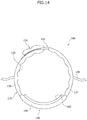
- the ultrasonic diagnostic apparatus 100 according to the fourth embodiment includes a fluid supply part 120 which supplies hydraulic pressure, a band member 130 wound around a diagnosis object 10 and connected to the fluid supply part 120 to be expanded by the hydraulic pressure, and an examination part 140 connected to the band member 130.
- the diagnosis object 10 is a person and the ultrasonic diagnostic apparatus 100 is wound around the neck 12 of the person for examination of the thyroid.
- the examination part 140 is positioned in front of the thyroid and the probe 142 in the examination part 140 provides ultrasound imagery of the thyroid while moving along the neck 12.
- the examination part 140 also includes an ultrasound permeable film and a mover that moves the probe 142 along the ultrasound permeable film.
- an ultrasound permeable film and a mover that moves the probe 142 along the ultrasound permeable film.
- the fluid supply part 120 is connected to the band member 130 via a fluid tube 136, so that hydraulic pressure generated in the fluid supply part 120 is applied to the band member 130 through the fluid tube 136.
- the ultrasonic diagnostic apparatus 100 is operated through manipulation of operation buttons 180, which include a first button 182 provided to the fluid supply part 120 and a second button 184 provided to the examination part 140.
- the fluid supply part 120 includes a main controller 122 which is disposed in the fluid supply part 120 and controls the ultrasonic diagnostic apparatus 100.
- the band member 130 configured to receive hydraulic pressure from the fluid supply part 120 includes a first band member 137 connected to one side of the examination part 140 and a second band member 138 connected to the other side of the examination part 140.
- the band member 130 may further include a first fastener 132 connected to the first band member 137 and a second fastener 134 connected to the second band member 138 to be fastened to the first fastener 132. Any members may be employed as the first and second fasteners 132, 138 so long as the members can be fastened to each other.
- fabric hook-and-loop fasteners such as Velcro fasteners may be provided as the first and second fasteners 132, 138.
- a ring member is used as the first fastener 132 and a fabric hook-and-loop fastener such as a Velcro fastener is used as the second fastener 134, thereby allowing easy adjustment in length and easy attachment/detachment of the band member 130.
- the band member 130 may be modified in various ways.
- the band member 130 may be connected to the opposite sides of the examination part 140 to surround the neck 12.
- the first band member 137 and the second band member 138 are connected to the opposite sides of the examination part 140.
- the examination part 140 is provided with a motion controller 156, which moves along with the probe 142 and is operated by manipulation of the second button 184 disposed on a cover 146 covering the motion controller 156.
- the motion controller 156 is connected to the main controller 122 via wired or wireless communication to send an ultrasound signal of the probe 142 thereto, and the main controller 122 converts the ultrasound signal into an image signal and sends the image signal to a display unit 190.
- the probe 142 is moved by manipulation of the second button 184 on the cover 146.
- a gel pad 160 may be disposed to adjoin the examination part 140. Obviously, the ultrasonic diagnostic apparatus may use the examination part 140 without the gel pad 160.
- the gel pad 160 includes an ultrasound permeable gel therein
- the gel pad 160 is in close contact with the neck 12 along the circumference thereof, thereby preventing measurement errors caused by the formation of a gap between the probe 142 and the diagnosis object 10.
- the ultrasonic diagnostic apparatus 100 is provided with a pressure sensor 170, which measures the degree of expansion of the band member 130 by operation of the fluid supply part 120 and sends the result to the motion controller 156.
- the pressure sensor 170 measures the pressure of the band member 130 so as to prevent the band member 130 from exceeding a preset pressure when compressing the neck 12.
- the pressure sensor 170 may be placed at any suitable location, as needed.
- the pressure sensor 170 may be disposed on an inner surface of the band member 140 contacting the neck 12 or inside the fluid supply part 120.
- Various images including the measurement results of the pressure sensor 170 and the ultrasound images obtained through the examination part 140 are delivered to the display unit 190 through the main controller 122.
- any gas such as air, nitrogen or the like may serve as the fluid.
- a liquid material may serve as the fluid.
- the band member 130 connected to the examination part 140 is wound around the neck 12 of the diagnosis object 10.
- the fabric hook-and-loop fastener provided as the second fastener 134 is inserted into the ring-shaped first fastener 132. After passing through the first fastener 132, the second fastener 134 is folded to obtain hook-and-loop fastening of the second fastener 134, so that the first fastener 132 and second fastener 134 are coupled to each other.
- An operator selectively manipulates the first button 182 on the fluid supply part 120 and the second button 184 on the examination part 140 to operate the ultrasonic diagnostic apparatus 100.
- the fluid supply part 120 When an operation signal is input through the operation buttons 180, the fluid supply part 120 is operated to generate hydraulic pressure, which in turn is supplied to the band member 130 through the fluid tube 136.
- the band member 130 is expanded by the hydraulic pressure, thereby forcing the examination part 140 in the direction of the neck 12 and ensuring stable contact therewith.
- the probe 142 is automatically moved or operated by manipulation of the second button 184 to perform ultrasonic diagnosis.
- the band member 130 is expanded so as to force the examination part 140 having the probe 142 in the direction of the diagnosis object 10, so that a gap is prevented from being formed between the probe 142 and the diagnosis object 10, thereby improving the reliability of the ultrasound imagery.
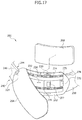
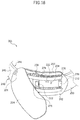
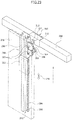
- Figs. 17 to 24 illustrate the ultrasonic diagnostic apparatus according to the fifth embodiment of the present disclosure.
- the ultrasonic diagnostic apparatus 201 includes a fastening part 240 having a band shape and wound around a diagnosis object 10, a first mover 270 which moves a probe 230 in a first direction 232 along the fastening part 240, and a second mover 290 which moves the probe 230 in a second direction 234 different from the first direction 232.
- the first direction 232 is the moving direction of the probe 230 when the probe 230 is longitudinally moved by operation of the first mover 270 (in Fig. 17 ), and the second direction 234 is the moving direction of the probe 230 when the probe 230 is transversely moved by operation of the second mover 290 (in Fig. 17 ).
- the first direction 232 and the second direction 234 are perpendicular to each other and the probe 230 provides ultrasound imagery of the diagnosis object 10 while moving in the first direction 232 or in the second direction 234.
- the first direction 232 and the second direction 234 are perpendicular to each other in this embodiment, it should be understood that the present disclosure is not limited thereto. Namely, the first direction 232 and the second direction 234 may be set to have any angle therebetween.
- the diagnosis object 10 is a person and the ultrasonic diagnostic apparatus 201 is wound around the neck 12 of the person to examine the thyroid.
- the fastening part 240 is wound around the neck 12 and the probe 230 provides ultrasound imagery of the thyroid while moving along the circumference of the neck 12.
- Any device may serve as the probe 230 for the ultrasonic diagnostic apparatus 201 so long as the device can obtain ultrasound images of the diagnosis object 10 while transmitting or receiving ultrasound signals.
- the fastening part 240 is wound around the diagnosis object 10, that is, the neck 12 of a person, and includes a first mover 270 and a second mover 290 disposed on a side surface of or inside the fastening part 240 to move the probe 230 automatically.
- Any stretchable member such as a string or band may serve as the fastening part 240 or any expandable member may serve as the fastening part 240 so long as the member allows the first mover 270 and the second mover 290 to be placed at any suitable location facilitating acquisition of ultrasound imagery of the diagnosis object 10.
- the fastening part 240 includes an ultrasound permeable film 242 disposed on the lateral side of the first mover 270 and a band member 244 connected to the ultrasound permeable film 242.
- the ultrasound permeable film 242 may be made of any stretchable material that has high permeability to ultrasound waves and can be wrapped around the neck 12.
- a gel pad 260 may be disposed to adjoin the ultrasound permeable film 242. Obviously, the ultrasonic diagnostic apparatus 201 may use the ultrasound permeable film 242 without the gel pad 260.
- the gel pad 260 is provided to one side of the ultrasound permeable film 242 facing the diagnosis object 10 and includes an ultrasound permeable gel therein.
- the gel pad 260 is in close contact with the neck 12 along the circumference thereof, thereby preventing measurement errors caused by the formation of a gap between the probe 230 and the diagnosis object 10.
- the band member 244 includes a first band member 246 connected to one side of the ultrasound permeable film 242 and a second band member 250 connected to the other side of the ultrasound permeable film 242.
- the band member 244 may further include a first fastener 48 connected to the first band member 246 and a second fastener 52 connected to the second band member 250 to be fastened to the first fastener 48. Any members may be employed as the first and second fasteners 48, 52 so long as the members can be fastened to each other.
- fabric hook-and-loop fasteners such as Velcro fasteners are provided as the first and second fasteners 48, 52, thereby allowing easy adjustment in length and easy attachment/detachment of the band member 244 to the object 10.
- any device may be employed as the first mover 270 provided to the ultrasound permeable film 242 so long as the device can move the probe 230 in a first direction 232 (longitudinal direction in Fig. 17 ).
- the first mover 270 includes a first drive member 272 for supplying rotational power, conveyor belts 274 moved by rotational power from the first drive member 272, a movable mounting part 276 moved in conjunction with the conveyor belts 274 and having the probe 230 secured to one side thereof, a drive gear 278 powered by the first drive member 272 and supporting one side of each of the conveyor belts 274, and a driven gear 280 supporting the other side of each of the conveyor belts 274.
- the first drive member 272 includes a motor for supplying rotational power and is secured to the ultrasound permeable film 242.
- the drive gear 278 is coupled to either side of a shaft extending through the first drive member 272 in a vertical direction (in Fig. 19 ).
- the drive gear 278 supports the one side (right side in Fig. 19 ) of each conveyor belt 274 and the driven gear 280 supports the other side (left side in Fig. 19 ) of each conveyor belt 274.
- the driven gear 280 is also coupled to either side of a connection bar, which connects both driven gears 280 such that the driven gears 280 are simultaneously rotated.
- the conveyor belt 274 has a threaded inner surface, which engages with the drive gear 278 and driven gear 280 to rotate therewith.
- the movable mounting part 276 is secured to the conveyor belts 174 and moved in the first direction 232 as the conveyor belts 274 move in the first direction.
- the movable mounting part 276 may be more stably moved in the first direction 232.
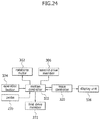
- the movable mounting part 276 is provided with a motion controller 322, which controls operations of the first drive member 272, the second drive member 306, a rotational motor 312, and the probe 230.
- the motion controller 322 is controlled by an operation button 324, which may be disposed on a cover 254 covering the ultrasound permeable film 242.
- the motion controller 322 is connected to a main controller 320 via wired or wireless communication to send an ultrasound signal of the probe 230 to the main controller 320, which in turn converts the ultrasound signal into an image signal and sends the image signal to a display unit 326.
- the first mover 270, the second mover 290 and a rotator 310 are operated by manipulation of the operation button 324 on the cover 254.
- the first and second drive members 272, 306 and the rotational motor 312 are powered via wired or wireless communication or by a separate battery in the fastening part 240.
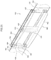
- the second mover 290 which moves the probe 230 in the second direction 234, is mounted on the rear of the movable mounting part 276 (in Fig. 20 ).
- the second mover 290 includes a guide rail 292 formed in the second direction 234 and having first teeth 294 formed on a side surface thereof, a movable bracket 298 moving along the guide rail 292, a rotational gear 302 formed on the movable bracket 298 and having second teeth 304 engaging with the first teeth 294, and a second drive member 306 rotating the rotational gear 302.
- the guide rail 292 extends in the second direction 234 and is mounted on the rear of the movable mounting part 276.
- the guide rail 292 has stoppers 296 protruding from upper and lower sides thereof to prevent detachment of the movable bracket 298 moving along the guide rail 292.
- the movable bracket 298 has a square pipe shape and is bent at opposite sides thereof to surround the first teeth 294 of the guide rail 292.
- the movable bracket 298 is formed at a side surface thereof with a connection hole 100, through which the first teeth 294 engage with the second teeth 304.
- the second teeth 304 of the rotational gear 302 engage with the first teeth 294 of the guide rail 292 through the connection hole 100 to rotate together.
- one or plural rotational gears 302 may be connected to the second drive member 306 and receive rotational power therefrom.
- the second drive member 306 is surrounded by a fixing bracket 308 and is fixed to the movable bracket 298.
- the rotator 310 is mounted on the movable bracket 298 of the second mover 290 and rotates the probe 230 in response to a control signal from the motion controller 322.
- the rotator 310 includes the rotational motor 312 for supplying rotational power and a rotational bracket 316 connected to an output shaft 314 of the rotational motor 312 while surrounding side surfaces of the probe 230.
- the rotational bracket 316 is connected to the output shaft 314 of the rotational motor 312 and may have various shapes including a squared "C" shape to surround the probe 230.
- the probe 230 for transmitting and receiving ultrasound waves is placed on the neck 12 in which the thyroid is positioned.
- the probe 230 is moved in the first direction 232 or the second direction 234 by manipulation of the operation button 324 while scanning the thyroid to generate thyroid ultrasound imagery.
- Rotation of the drive gears 278 leads to rotation of the conveyor belts 274 between the drive gears 278 and the driven gears 280.
- the movable mounting part 276 secured to the conveyor belts 274 is also moved together with the conveyor belts 274, so that the probe 230 attached to the movable mounting part 276 is also moved in the first direction 232 while scanning the thyroid to generate thyroid ultrasound imagery.
- the motion controller 322 calculates a current location of the probe 230 and adjusts rotation of the first drive member 272 in a forward or rearward direction so as to move the probe 230 in the longitudinal direction (in Fig. 18 ).
- the probe 230 is also horizontally moved (in Fig. 22 ).
- the second drive member 306 is operated to rotate the rotational gears 302, so that the second teeth 304 of the rotational gears 302 engage with the first teeth 294 of the guide rail 292 to rotate together, thereby moving the movable bracket 298 in the second direction 234.
- the probe 230 is also vertically moved while scanning the thyroid to generate thyroid ultrasound imagery.
- an ultrasound signal is transmitted from the probe 230 to the main controller 320 via the motion controller 322. Then, the main controller 320 converts the ultrasound signal into an image signal and sends the image signal to the display unit 326, thereby providing thyroid ultrasound imagery.
- the probe 230 mounted on the mover 30 or 32 provides consistent quality ultrasound images of the diagnosis object 10 while the first mover 270 moves along the fastening part 240 securely wrapped around the diagnosis object 10, thereby guaranteeing improved reliability of ultrasonic diagnosis.
- the probe 230 is horizontally moved along the first mover 270 and vertically moved along the second mover 290, thereby providing more accurate ultrasound images than when configured to move in only one direction.
- the first mover 270 and the second mover 290 may be operated to adjust the location of the probe corresponding to different locations of the thyroids of individuals.
- Figs. 25 to 29 illustrate the ultrasonic diagnostic apparatus according to the sixth embodiment of the present disclosure.
- the ultrasonic diagnostic apparatus 401 includes a probe 420 for probing a diagnosis object 10, a gel pad part 450 to be brought into contact with the diagnosis object 10, and a band member 440 connected to the gel pad part 450 and wound around the diagnosis object 10.
- the diagnosis object 10 is a person and the ultrasonic diagnostic apparatus 401 is wrapped around the neck 12 of the person to examine the thyroid in the neck.
- the gel pad part 450 and the band member 440 are configured to be wound around the neck 12, so that the probe 420 disposed inside the gel pad part 450 performs ultrasound examination of the thyroid while moving along the circumference of the neck 12.
- Any device may serve as the probe 420 for the ultrasonic diagnostic apparatus 401 so long as the device can obtain ultrasound images of the diagnosis object 10 while transmitting or receiving ultrasound signals.
- the probe 420 and a mover 430 for automatically moving the probe 420 are disposed within the gel pad part 450.
- the gel pad part 450 is kept in close contact with the diagnosis object 10 to prevent a gap from being formed between the probe 420 and the diagnosis object 10. Any member may serve as the gel pad part 450 so long as the member can provide such a function of the gel pad part 450 according to this embodiment.
- the gel pad part 450 includes a gel pad 452, which is connected at both sides thereof to the band member 440.
- the gel pad 452 is in close contact with the neck 12 along the circumference thereof, thereby preventing measurement errors caused by the formation of a gap between the probe 420 and the diagnosis object 10.
- any device may be employed as the mover 430 for the ultrasonic diagnostic apparatus 401 so long as the device can move the probe 230 within the gel pad 452.
- the mover 430 includes a drive member 432 for supplying rotational power, conveyor belts 433 moved by rotational power from the drive member 432, a movable mounting part 434 moved in conjunction with the conveyor belts 433 and having the probe 420 secured to one side thereof, a drive gear 435 powered by the drive member 432 and supporting one side of each conveyor belt 433, and a driven gear 280 supporting the other side of each conveyor belt 433.
- the drive member 432 includes a motor for supplying rotational power and is secured to an inner side of the gel pad 452.
- the drive gear 435 is coupled to either side of a shaft extending through the drive member 432 in a vertical direction (in Fig. 29 ).
- the drive gear 435 supports the one side (right side in Fig. 29 ) of each conveyor belt 433 and the driven gear 436 supports the other side (left side in Fig. 29 ) of each conveyor belt 433.
- the driven gear 436 is also coupled to either side of a connection bar 437, which connects both driven gears 436 such that the driven gears 436 are simultaneously rotated.
- connection bar 437 penetrates a mounting bracket 438 and ring-shaped restriction members 439 are secured to the connection bar 437.
- the mounting bracket 438 is secured to a side surface of the gel pad 452 to allow stable rotation of the driven gears 436 and the restriction members 439 are secured to the connection bar 437 to restrict vertical movement of the connection bar 437.
- the conveyor belt 433 has a threaded inner surface, which engages with the drive gear 435 and driven gear 436 to rotate therewith.
- a movable mounting part 434 having a plate shape is secured to the conveyor belts 433, so that the movable mounting part 434 having the probe 420 mounted thereon is moved in unison with the conveyor belts 433.
- the conveyor belts 433 are disposed at opposite sides of the movable mounting part 434 (at upper and lower sides of the movable mounting part 434 in Fig. 27 ).
- the movable mounting part 434 is provided with a motion controller 480, which controls operations of the drive member 432 and the probe 420.
- the motion controller 480 is operated by a button 425, which may be provided to the gel pad 452 or the band member 440.
- the motion controller 480 is connected to a main controller 74 via wired or wireless communication to send an ultrasound signal of the probe 420 to the main controller 74, which in turn converts the ultrasound signal into an image signal and sends the image signal to a display unit 76.
- the ultrasonic diagnostic apparatus 401 selectively includes at least one of the motion controller 480 and the main controller 74.
- the drive member 432 and the motion controller 480 may be powered via wired or wireless communication or by a separate battery in the gel pad 452 or the band member 440.
- Any stretchable member such as a string or band may be employed as the band member 440 so long as the member allows the mover 430 to be positioned at any suitable location facilitating acquisition of the ultrasound imagery of the diagnosis object 10.
- the band member 440 may include a first band member 442 connected to one side of the gel pad part 450 and a second band member 446 connected to the other side of the gel pad part 450.
- the band member 440 may further include a first fastener 444 connected to the first band member 442 and a second fastener 448 connected to the second band member 446 to be fastened to the first fastener 444. Any members may be employed as the first and second fasteners 444, 448 so long as the members can be fastened to each other.
- fabric hook-and-loop fasteners such as Velcro fasteners are provided as the first and second fasteners 444, 448, thereby allowing easy adjustment in length and easy attachment/detachment of the band member 440 to the object 10.
- the first fastener 444 is fastened to the second fastener 448 to secure the location of the gel pad part 450 with respect to the neck 12.
- the probe 420 is moved within the gel pad part 450 by manipulation of the button 425 while scanning the thyroid to generate thyroid ultrasound imagery.
- a signal is transmitted to the motion controller 480 by manipulation of the button 425 and power is supplied to the drive member 432 under control of the motion controller 480 to generate rotational power.
- the drive member 432 is operated, the drive gears 435 located at the upper and lower sides of the drive member 432 are rotated.
- Rotation of the drive gears 435 leads to rotation of the conveyor belts 433 between the drive gear 435 and the driven gear 436.
- the movable mounting part 434 secured to the conveyor belts 433 is also moved together with the conveyor belts 433, so that the probe 420 attached to the movable mounting part 434 is also moved in the moving direction of the conveyor belts 433 while scanning the thyroid to generate thyroid ultrasound imagery.
- the main controller 74 or the motion controller 480 calculates a current location of the probe 420 and adjusts rotation of the drive member 432 in a forward or rearward direction so as to move the probe 420 in the longitudinal direction ( Fig. 27 ).
- the gel pad 452 surrounding the mover 430 is disposed to surround the neck 12 having a curved shape, it is possible to reduce measurement errors that can occur due to the formation of pockets of air between the probe 420 and the diagnosis object 10 during ultrasonic diagnosis.
- ultrasound signals are transmitted from the probe 420 to the main controller 74 via the motion controller 480.
- the main controller 74 converts the ultrasound signals into image signals and sends the image signals to the display unit 76, thereby providing thyroid ultrasound imagery.
- Fig. 30 is a plan view of a mover of the ultrasonic diagnostic apparatus according to the seventh embodiment
- Fig. 31 is a perspective view of the mover of the ultrasonic diagnostic apparatus according to the seventh embodiment
- Fig. 32 is a perspective view of a probe of Fig. 29 , which moves along conveyor belts.
- the ultrasonic diagnostic apparatus 402 includes a gel pad part 460 disposed to adjoin a side surface of a mover 430.
- the gel pad part 460 includes a gel therein and adjoins a probe 420 moving together with a movable mounting part 434. Thus, the gel pad part 460 is longitudinally disposed along a movement path of the probe 420.
- An exterior member 464 covers the mover 430 to protect the mover 430 from the outside.
- the exterior member 464 is provided with a button 425 which is used to control the mover 430.
- the probe 420 is moved in a stat of adjoining the gel pad part 460 by operation of the mover 430 when probing the diagnosis object 10.
- a gel pad 462 is disposed between the probe 420 and a body surface of the diagnosis object 10, so that a difference in acoustic impedance between the probe 420 and the body surface can be gradually reduced to prevent attenuation of acoustic signals, thereby improving the quality of the ultrasound imagery.
- the gel pad 462 is disposed between the probe and the diagnosis object, so that a Fresnel Zone created near the probe and having a complex ultrasonic field due to non-uniform acoustic signal intensity is distant from the diagnosis object, thereby improving the quality of the ultrasound imagery.
- the ultrasonic diagnostic apparatus includes a fastening part secured to a diagnosis object and a mover moving along the fastening part to obtain consistent quality ultrasound images of the diagnosis object, thereby improving reliability of ultrasonic diagnosis.
- the ultrasonic diagnostic apparatus may reduce user fatigue by allowing automatic movement of the probe, thereby enhancing operability during ultrasonic diagnosis.
- the ultrasound permeable film may be flexibly bent and the gear rack may also be bent in the same direction as that of the ultrasound permeable film, so that the probe provided to the movable examination part can scan the diagnosis object along the circumference of the object without resistance.
- the ultrasonic diagnostic apparatus allows the probe to move on the diagnosis object in the longitudinal direction of the ultrasound permeable film, so that the probe can contact a wide region regardless of the curvature of the diagnosis object, thereby guaranteeing a wide diagnosis area.
- the ultrasonic diagnostic apparatus allows scanning of the diagnosis object without direct manual user manipulation and thus provides consistent quality ultrasound images of patients, thereby enhancing reliability of ultrasonic diagnosis.
- the ultrasonic diagnostic apparatus is provided with an examination part including the probe, such that the examination part can be brought into close contact with the diagnosis object by expansion of a band member to prevent a gap from being formed between the probe and the diagnosis object during diagnosis, thereby improving the quality of the ultrasound imagery.
- the ultrasonic diagnostic apparatus is provided with a gel pad, such that the gel pad can be brought into close contact with the diagnosis object to prevent a gap from being formed between the probe and the diagnosis object during diagnosis, thereby improving the quality of the ultrasound imagery.
- the gel pad having a predetermined thickness is disposed between the neck as the diagnosis object and the probe, thereby improving the quality of the ultrasound imagery by eliminating diffuse reflection of ultrasound waves that can occur when the probe is located near the diagnosis object.
- the gel pad needs to be replaced frequently, the gel pad according to the embodiments may be easily attached to or detached from an ultrasound permeable film to facilitate repair and maintenance of the gel pad.
- the gel pad is disposed between the probe and a body surface of the diagnosis object, so that a difference in acoustic impedance between the probe and the body surface is gradually reduced to prevent attenuation of acoustic signals, thereby improving the quality of the ultrasound imagery.
- the gel pad is disposed between the probe and the diagnosis object, so that a Fresnel Zone created near the probe is distant from the diagnosis object, thereby improving the quality of the ultrasound imagery.
- the ultrasonic diagnostic apparatus according to the embodiments of the present disclosure is obviously applicable to other parts of a person for ultrasonic diagnosis.
- the scope of the present disclosure should be limited only by the accompanying claims.
Landscapes
- Life Sciences & Earth Sciences (AREA)
- Health & Medical Sciences (AREA)
- Biomedical Technology (AREA)
- Biophysics (AREA)
- Nuclear Medicine, Radiotherapy & Molecular Imaging (AREA)
- Pathology (AREA)
- Radiology & Medical Imaging (AREA)
- Engineering & Computer Science (AREA)
- Physics & Mathematics (AREA)
- Heart & Thoracic Surgery (AREA)
- Medical Informatics (AREA)
- Molecular Biology (AREA)
- Surgery (AREA)
- Animal Behavior & Ethology (AREA)
- General Health & Medical Sciences (AREA)
- Public Health (AREA)
- Veterinary Medicine (AREA)
- Ultra Sonic Daignosis Equipment (AREA)
Description
- The present disclosure relates to an ultrasonic diagnostic apparatus and, more particularly, to an ultrasonic diagnostic apparatus which allows a probe to move along a diagnosis object having a rounded surface or protruded portion so as to facilitate ultrasonic diagnosis on the rounded surface or protuberances of the object.
- Generally, an ultrasonic diagnostic apparatus refers to a non-invasive apparatus that irradiates an ultrasound signal from a surface of a patient body towards a target internal organ beneath the body surface and obtains an image of a monolayer or blood flow in soft tissue from information in the reflected ultrasound signal (ultrasound echo-signal).
- The ultrasonic diagnostic apparatus has been widely used for diagnosis of the heart, the abdomen, the urinary organs, and in obstetrics and gynecology due to various merits thereof such as small size, low price, real-time image display, and high stability through elimination of radiation exposure, as compared with other image diagnostic systems, such as X-ray diagnostic systems, computerized tomography scanners (CT scanners), magnetic resonance imagers (MRIs), nuclear medicine diagnostic apparatuses, and the like. Document
US2009/0036780 describes that the ultrasonic arrays and imaging apparatus may be remotely controlled as to rotation, linear movement and pitch. Further, infigures 1a, 1b it depicts a housing 103, cable 104 and a fastening or securing material 105. - Document
WO2006/131881 (figures 1 ,4 ,5 ) suggests asystem 1, which comprises a probe holder 2 to which a probe 4 is rigidly attachable. The probe holder 2 is moveable along at least one rail 5, 5'. The rail can be wrapped around a body part 7 of the patient or the animal. - Document
WO2007/130526 describes a probe translation assembly comprising rigid, curved racks 902, a motor 904, and a gear/pinion 906 configured such that theultrasound probe 302 moves along the curved racks 902 according to actuation of the motor 904 (figures 9 ,10 ). - The ultrasonic diagnostic apparatus includes a probe which transmits an ultrasound signal to a diagnosis object and receives the ultrasound signal reflected therefrom to obtain ultrasound images of the diagnosis object. A controller displays the signal sent from the probe on a display screen, so that a user can diagnose the object while alternately viewing the screen and the object.
- Meanwhile, a diagnosis of thyroid cancer or hyperthyroidism must be verified through ultrasound examination of the neck region. Ultrasound scanning for thyroid examination is conducted using a probe around the neck of a patient laid on an examination table. Here, it should be noted that the above description is provided for understanding of the background art and is not a description of a well-known conventional technique to which the present disclosure pertains.
- In ultrasonic diagnosis for thyroid examination, since the neck has a rounded circumference and protuberances, a user of the ultrasonic diagnostic apparatus grips and moves the probe along the neck to scan the thyroid. Such manipulation of the probe for thyroid examination can provide non-uniform ultrasound images depending on user's skill, thereby lowering reliability of the ultrasonic diagnosis. Moreover, since a user must move the probe along a rounded surface or protuberances of the neck, the user may experience wrist strain or the like. Therefore, there is a need for an improved ultrasonic diagnostic apparatus.
- The invention is defined in the
independent claim 1, preferred embodiments are defined in the dependent claims. - The present disclosure is directed to solving such problems of the related art, and an aspect of the present disclosure is to provide an ultrasonic diagnostic apparatus which guarantees reliability in ultrasonic diagnosis of an object including the neck regardless of user's skill.
- Another aspect of the present disclosure is to provide an ultrasonic diagnostic apparatus which may reduce user fatigue.
- A further aspect of the present disclosure is to provide an ultrasonic diagnostic apparatus which allows a probe to be brought into close contact with a diagnosis object so as not to form a gap between the probe and the diagnosis object during diagnosis.
- Yet another aspect of the present disclosure is to provide an ultrasonic diagnostic apparatus which can prevent significant acoustic reflection or multiple reflection by repeated reflection on a contact surface between the probe and a body surface such as the skin due to a large difference in acoustic impedance therebetween when the probe is brought into direct contact with the body surface, thereby solving the problem of deterioration in quality of ultrasound images resulting from poor transmission of acoustic signals through the skin during diagnosis.
- Yet another aspect of the present disclosure is to provide an ultrasonic diagnostic apparatus which can solve the problem of deterioration in quality of ultrasound images due to a Fresnel Zone created near the probe and having a complex ultrasonic field due to non-uniform acoustic signal intensity, when the probe is brought into direct contact with the body surface.
- In accordance with one aspect, an ultrasonic diagnostic apparatus includes: a fastening part having a band shape and wound around a diagnosis object; and a mover moving a probe along the fastening part.
- The fastening part may include an ultrasound permeable film connected to the mover and a band member connected to the ultrasound permeable film.
- The band member may include a first band member connected to one side of the ultrasound permeable film and a second band member connected to the other side of the ultrasound permeable film.
- The apparatus may further include a fluid supply part connected to the first and second band members to supply hydraulic pressure. The first and second band members are expanded by the hydraulic pressure.
- The apparatus may further include a gel pad having a gel therein and disposed on one side of the ultrasound permeable film facing the diagnosis object.
- The fastening part may include a resilient gel pad disposed in a moving direction of the mover to surround the mover, and a band member connected to the gel pad.
- The probe may be moved in a state of contacting an outer surface of the gel pad when probing the diagnosis object.
- The probe may be disposed within the gel pad.
- The mover may include a drive member supplying rotational power, a conveyor belt moved by rotation of the drive member, and a movable mounting part moved in conjunction with the conveyor belt and having the probe secured to one side thereof.
- The mover according to the invention includes a gear rack disposed on the fastening part in a longitudinal direction in which the probe is moved, and a movable examination part moving along the gear rack and having the probe secured to a side surface thereof.
- The movable examination part according to the invention includes a pinion member engaging with the gear rack, a transport motor driving the pinion member, and a movable plate on which the transport motor, pinion member and probe are mounted.
- The mover may include a first mover moving the probe in a first direction along the fastening part and a second mover moving the probe in a second direction different from the first direction along the fastening part.
- The first mover may include a first drive member supplying rotational power, a conveyor belt moved by rotation of the first drive member, and a movable mounting part moved in conjunction with the conveyor belt and having the probe secured to one side thereof. The second mover may include a guide rail formed in the second direction and having first teeth formed on a side surface of the guide rail, a movable bracket moving along the guide rail, a rotational gear formed on the movable bracket and having second teeth engaging with the first teeth, and a second drive member rotating the rotational gear.
- The mover may further include a rotator rotating the probe.
- The rotator may include a rotational motor supplying rotational power and a rotational bracket connected to an output shaft of the rotational motor while surrounding a side surface of the probe.
- The above and other aspects, features and advantages of the present disclosure will become apparent from the following description of the following embodiments given in conjunction with the accompanying drawings, in which:
-
Fig. 1 is a perspective view of an ultrasonic diagnostic apparatus according to a first embodiment of the present disclosure in use; -
Fig. 2 is a perspective view of the ultrasonic diagnostic apparatus according to the first embodiment of the present disclosure; -
Fig. 3 is an exploded perspective view of the ultrasonic diagnostic apparatus according to a first exemplary embodiment; -
Fig. 4 is a perspective view of the ultrasonic diagnostic apparatus according to the first exemplary embodiment, showing a movable mounting part that moves on conveyor belts inFig. 3 ; -
Fig. 5 is an exploded perspective view of a mover of the ultrasonic diagnostic apparatus according to the first exemplary embodiment; -
Fig. 6 is a block diagram of the ultrasonic diagnostic apparatus according to the first exemplary embodiment; -
Fig. 7 is an exploded perspective view of an ultrasonic diagnostic apparatus according to a second embodiment, which is in accordance with the invention; -
Fig. 8 is a perspective view of a mover of the ultrasonic diagnostic apparatus according to the second embodiment of the present disclosure; -
Fig. 9 is an exploded perspective view of an ultrasonic diagnostic apparatus according to a third exemplary embodiment; -
Fig. 10 is a plan view of the ultrasonic diagnostic apparatus ofFig. 9 ; -
Fig. 11 is a perspective view of an ultrasonic diagnostic apparatus according to a fourth embodiment of the present disclosure in use; -
Fig. 12 is a perspective view of the ultrasonic diagnostic apparatus according to the fourth exemplary embodiment; -
Fig. 13 is an exploded perspective view of the ultrasonic diagnostic apparatus ofFig. 12 , showing a first fastener and a second fastener fastened to each other; -
Fig. 14 is a plan view of the ultrasonic diagnostic apparatus according to the fourth exemplary embodiment before hydraulic pressure is applied to a fluid expansion part; -
Fig. 15 is a plan view of the ultrasonic diagnostic apparatus according to the fourth exemplary embodiment after hydraulic pressure is applied to the fluid expansion part; -
Fig. 16 is a block diagram of the ultrasonic diagnostic apparatus according to the fourth exemplary embodiment; -
Fig. 17 is an exploded perspective view of an ultrasonic diagnostic apparatus according to a fifth exemplary embodiment, showing a first mover in the ultrasonic diagnostic apparatus; -
Fig. 18 is a perspective view of the ultrasonic diagnostic apparatus according to the fifth exemplary embodiment, showing a movable mounting part that moves on conveyor belts inFig. 17 ; -
Fig. 19 is an exploded perspective view of the ultrasonic diagnostic apparatus according to the fifth exemplary embodiment, showing a fist mover, a second mover and a rotator in the ultrasonic diagnostic apparatus; -
Fig. 20 is an exploded perspective view of a rotational gear and a second drive member detached from a movable bracket ofFig, 19 ; -
Fig. 21 is a perspective view of a probe disposed in the ultrasonic diagnostic apparatus according to the fifth exemplary embodiment; -
Fig. 22 is a perspective view of the probe ofFig. 21 when the probe is moved perpendicular to the guide rail; -
Fig. 23 is a perspective view of the probe ofFig. 22 when the probe is moved in a second direction; -
Fig. 24 is a block diagram of the ultrasonic diagnostic apparatus according to the fifth exemplary embodiment; -
Fig. 25 is a perspective view of an ultrasonic diagnostic apparatus according to a sixth exemplary embodiment; -
Fig. 26 is a plan view of a mover of the ultrasonic diagnostic apparatus according to the sixth exemplary embodiment; -
Fig. 27 is a perspective view of the mover of the ultrasonic diagnostic apparatus according to the sixth exemplary embodiment; -
Fig. 28 is a perspective view of a probe ofFig. 27 , which moves along conveyor belts; -
Fig. 29 is an exploded perspective view of the mover according to the sixth exemplary embodiment; -
Fig. 30 is a plan view of a mover of an ultrasonic diagnostic apparatus according to a seventh exemplary embodiment; -
Fig. 31 is a perspective view of the mover of the ultrasonic diagnostic apparatus according to the seventh exemplary embodiment; and -
Fig. 32 is a perspective view of a probe ofFig. 29 , which moves along conveyor belts. - Embodiments of the present disclosure will now be described in detail with reference to the accompanying drawings. In descriptions of the following embodiments, an ultrasonic diagnostic apparatus for thyroid examination will be described by way of example. It should be noted that the drawings are not to precise scale and may be exaggerated in thickness of lines or size of components for descriptive convenience and clarity. Furthermore, terms used herein are defined by taking functions of the present disclosure into account and can be changed according to the custom or intention of users or operators. Therefore, definition of the terms should be made according to overall disclosures set forth herein.
-
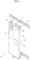
Figs. 1 to 6 show an ultrasonic diagnostic apparatus according to a first embodiment. Referring toFigs. 1 to 6 , an ultrasonicdiagnostic apparatus 1 according to the first embodiment includes afastening part 20 that has a band shape and is wound around adiagnosis object 10, and amover 30 that moves aprobe 14 for transmitting and receiving ultrasound signals along thefastening part 20. - In the first embodiment, the
diagnosis object 10 is a person and the ultrasonicdiagnostic apparatus 1 is wound around theneck 12 of the person for thyroid examination. - The
fastening part 20 is wound around theneck 12, and theprobe 14 is used to perform ultrasound examination of the thyroid while moving along the circumference of theneck 12. - Any device may serve as the
probe 14 for the ultrasonicdiagnostic apparatus 1 so long as the device can obtain ultrasound images of thediagnosis object 10 while transmitting or receiving ultrasound signals. - The
fastening part 20 is wound around thediagnosis object 10 such as theneck 12 of a person and themover 30 is disposed on a side surface of or inside thefastening part 20 to move theprobe 14 automatically. - Any stretchable member such as a string or band may serve as the
fastening part 20 so long as the member allows themover 30 to be positioned at any suitable location facilitating acquisition of ultrasound imagery of thediagnosis object 10. - In the first embodiment, the
fastening part 20 includes an ultrasoundpermeable film 24 connected to themover 30 and aband member 26 connected to the ultrasoundpermeable film 24. - The ultrasound
permeable film 24 may be made of any stretchable material that has high permeability to ultrasound waves and can be wrapped around theneck 12. - A
gel pad 22 may be disposed to adjoin the ultrasoundpermeable film 24. Obviously, the ultrasonicdiagnostic apparatus 1 may use the ultrasoundpermeable film 24 without thegel pad 22. - The
gel pad 22 is provided to one side of the ultrasoundpermeable film 24 facing thediagnosis object 10 and includes an ultrasound permeable gel therein. - When the
probe 14 is used to examine theneck 12, thegel pad 22 is in close contact with theneck 12 along the circumference thereof, thereby preventing measurement errors caused by the formation of a gap between theprobe 14 and thediagnosis object 10. - The
band member 26 includes afirst band member 90 connected to one side of the ultrasoundpermeable film 24 and asecond band member 92 connected to the other side of the ultrasoundpermeable film 24. - The
band member 26 may further include afirst fastener 27 connected to thefirst band member 90 and asecond fastener 28 connected to thesecond band member 92 to be fastened to thefirst fastener 27. Any members may be employed as the first andsecond fasteners - In this embodiment, fabric hook-and-loop fasteners such as Velcro fasteners are provided as the first and
second fasteners band member 26 to theobject 10. - Any device may be employed as the
mover 30 provided to the ultrasoundpermeable film 24 so long as the device can move theprobe 14 in a longitudinal direction (inFig. 4 ). - In the first embodiment, the
mover 30 includes adrive member 40 for supplying rotational power,conveyor belts 42 moved by rotation of thedrive member 40, a movable mountingpart 44 moved in conjunction with theconveyor belts 42 and having theprobe 14 secured to one side thereof, adrive gear 46 powered by thedrive member 40 and supporting one side of each of theconveyor belts 42, and a drivengear 48 supporting the other side of each of theconveyor belts 44. - The
drive member 40 includes a motor for supplying rotational power and is secured to the ultrasoundpermeable film 24. - The
drive gear 46 is coupled to either side of a shaft extending through thedrive member 40 in a vertical direction (inFig. 5 ). - The
drive gear 46 supports the one side (right side inFig. 5 ) of eachconveyor belt 42 and the drivengear 48 supports the other side of eachconveyor belt 42. - The driven
gear 48 is also coupled to either side of a connection bar, which connects both driven gears 45 such that the driven gears 45 are simultaneously rotated. - The
conveyor belt 42 has a threaded inner surface, which engages with thedrive gear 46 and drivengear 48 to rotate therewith. - With the
probe 14 mounted on the movable mountingpart 44, the movable mountingpart 44 is secured to theconveyor belts 42 and moved in conjunction with theconveyor belts 42. - Since the
conveyor belts 42 are disposed at opposite sides of the movable mountingpart 44, the movable mountingpart 44 may be more stably moved in the longitudinal direction of the conveyor belts 42 (inFig. 5 ). - The movable mounting
part 44 is provided with amotion controller 72 which controls operation of thedrive member 40 andprobe 14. - The
motion controller 72 is controlled by abutton 70, which may be disposed on acover 29 covering the ultrasoundpermeable film 24. - The
motion controller 72 is connected to amain controller 74 via wired or wireless communication to send an ultrasound signal of theprobe 14 thereto, and themain controller 74 converts the ultrasound signal into an image signal and sends the image signal to adisplay unit 76. - The
mover 30 is operated by manipulation of thebutton 70 on thecover 26 and thedrive member 40 is powered via wired or wireless communication or by a separate battery in thefastening part 20. - Next, operation of the ultrasonic diagnostic apparatus according to the first embodiment will be described with reference to the accompanying drawings.
- With the
fastening part 20 wound around theneck 12 of adiagnosis object 10, thefirst fastener 27 is fastened to thesecond fastener 28 to secure thefastening part 20 to theneck 12. - With the
fastening part 20 secured to theneck 12, themover 30 including theprobe 14 is placed in front of theneck 12 where the thyroid is located (at the left side inFig. 1 ). - When a user presses the
button 70, power is supplied to thedrive member 40 to generate rotational power, which is transmitted to and rotates the drive gears 46 located at the opposite sides of thedrive member 40. - Rotation of the drive gears 46 leads to rotation of the
conveyor belts 42 between the drive gears 46 and the driven gears 48. - The movable mounting
part 44 secured to theconveyor belts 42 is also moved together with theconveyor belts 42 and theprobe 14 mounted on the movable mountingpart 44 is also moved while scanning the thyroid to generate thyroid ultrasound imagery. - Since the
gel pad 22 attached to the rear of the ultrasoundpermeable film 24 is disposed to surround theneck 12 having a curved shape, it is possible to reduce measurement errors that can occur due to the formation of pockets of air between theprobe 14 and thediagnosis object 10 during ultrasonic diagnosis. - The
motion controller 72 calculates a current location of theprobe 14 and adjusts rotation of thedrive member 40 in a forward or rearward direction to move theprobe 14 in the longitudinal direction (inFig. 4 ). - Then, an ultrasound signal is transmitted from the
probe 14 to themain controller 74 via themotion controller 72. Then, themain controller 62 converts the ultrasound signal into an image signal and sends the image signal to thedisplay unit 66, thereby providing thyroid ultrasound imagery. - Next, an ultrasonic diagnostic apparatus 2 according to a second embodiment will be described with reference to the accompanying drawings.
- For convenience of description, the same elements as those of the first embodiment will be denoted by the same reference numerals and elaboration thereof will be omitted herein.
-
Fig. 7 is an exploded perspective view of an ultrasonic diagnostic apparatus according to a second embodiment andFig. 8 is a perspective view of a mover of the ultrasonic diagnostic apparatus according to the second embodiment. - Referring to
Figs. 7 and8 , amover 32 of the ultrasonic diagnostic apparatus 2 according to this embodiment includes gear racks 50 disposed on afastening part 20 in a longitudinal direction in which aprobe 14 is moved, and amovable examination part 60 moving along the gear racks 50 and having theprobe 14 secured to a side surface of themovable examination part 60. - The gear racks 50 are respectively secured to opposite sides of an ultrasound
permeable film 24 and both of the gear racks 50 and the ultrasoundpermeable film 24 are made of a flexible material. - Since the gear racks 50 are disposed at the opposite sides of the
movable examination part 60 including the probe 14 (inFig. 7 ), themovable examination part 60 may be more stably moved in the longitudinal direction of the gear racks 50. - In the second embodiment, the
movable examination part 60 includespinion members 62, which engage with and rotate on the gear racks 50, atransport motor 64 driving thepinion members 62, amovable plate 66 on which thetransport motor 64,pinion members 62 andprobe 14 are mounted, and anti-separation rings 68 each bent at opposite sides of themovable plate 66 to catch lateral sides of thefastening part 20. - Each of the anti-separation rings 68 extends across the
movable plate 66 and is bent at the opposite sides of themovable plate 66. Since both sides of each of the anti-separation rings 68 extend to and catch the rear side of the ultrasoundpermeable film 24, the anti-separation rings 68 prevent separation of themovable plate 66 from themovable examination part 60. - The
movable plate 66 is provided with amotion controller 72, which controls operation of thetransport motor 64 which rotates thepinion members 62 engaging with the gear racks 50. - One of the
pinion members 62 may be disposed under themovable plate 66 to engage with and rotate on the gear rack 51. - Next, operation of the ultrasonic diagnostic apparatus 2 according to the second embodiment will be described with reference to the accompanying drawings.
- When a user presses a
button 70, power is supplied to thetransport motor 64 to generate rotational power, which is transmitted to and rotates thepinion members 62 connected to thetransport motor 64. - Since the
pinion members 62 engage with and rotate on the gear racks 50, themovable plate 66 including theprobe 14 is horizontally moved along the gear racks 50 (inFig. 8 ). - The
probe 14 attached to themovable plate 66 is also horizontally moved while scanning theneck 12 to generate thyroid ultrasound imagery. - The
motion controller 72 calculates a current location of theprobe 14 and adjusts rotation of thetransport motor 64 in a forward or rearward direction to move theprobe 14 in the longitudinal direction (inFig. 8 ). - Next, an ultrasonic diagnostic apparatus 3 according to a third embodiment will be described with reference to the accompanying drawings.
- For convenience of description, the same elements as those of the first embodiment will be denoted by the same reference numerals and elaboration thereof will be omitted herein.
-
Fig. 9 is an exploded perspective view of an ultrasonic diagnostic apparatus according to a third embodiment andFig. 10 is a plan view of the ultrasonic diagnostic apparatus ofFig. 9 . - Referring to
Figs. 9 and10 , in the ultrasonic diagnostic apparatus 3 according to the third embodiment, afastening part 21 includes aresilient gel pad 22 disposed in a moving direction of amover 30 to surround themover 30, and aband member 26 connected to thegel pad 22. - In the
mover 30 of the ultrasonic diagnostic apparatus,conveyor belts 42 are disposed within thegel pad 22, and a movable mountingpart 44 and aprobe 14 moving along theconveyor belts 42 are also disposed within thegel pad 22. - A
drive member 40, drive gears 46 and drivengears 48 are disposed outside or inside thegel pad 22 to rotate theconveyor belts 42. - The
drive member 40, drive gears 46 and drivengears 48 disposed outside thegel pad 22 are encased in a side cover 80 to be isolated from the outside. - In the ultrasonic diagnostic apparatus 3 according to this embodiment, the ultrasound
permeable film 24 and the cover 36 of the first embodiment are omitted, thereby reducing manufacturing costs. - Next, operation of the ultrasonic diagnostic apparatus 3 according to the third embodiment will be described with reference to the accompanying drawings.
- When a user presses a button (not shown) on the
fastening part 21, power is supplied to thedrive member 40 to generate rotational power, which is transmitted to and rotates the drive gears 46 located at opposite sides of the drive member 40 (inFig. 9 ). - Rotation of the drive gears 46 leads to rotation of the
conveyor belts 42 between the drive gears 46 and the driven gears 48 within thegel pad 22. - Then, the movable mounting
part 44 secured to theconveyor belts 42 is moved in conjunction with theconveyor belts 42 within thegel pad 22. - The
probe 14 attached to the movable mountingpart 44 is also horizontally moved while scanning theneck 12 to generate thyroid ultrasound imagery. Here, since only an ultrasound permeable gel is disposed between theprobe 14 and theneck 12, it is possible to reduce measurement errors that can occur due to the formation of pockets of air therebetween. - The
motion controller 72 calculates a current location of theprobe 14 and adjusts rotation of thedrive member 40 in a forward or rearward direction so as to allow theprobe 14 to move within thegel pad 22. - Accordingly, in each of the ultrasonic
diagnostic apparatuses 1, 2 or 3 according to the embodiments described above, theprobe 14 mounted on themover diagnosis object 10 while themover fastening part diagnosis object 10, thereby guaranteeing improved reliability of ultrasonic diagnosis. - In addition, since the
probe 14 is automatically moved on the fastening part, the ultrasonic diagnostic apparatus may guarantee improved operability by reducing user fatigue. - Next, an ultrasonic
diagnostic apparatus 100 according to a fourth embodiment will be described with reference to the drawings. -
Figs. 11 to 16 illustrate the ultrasonic diagnostic apparatus according to the fourth embodiment. InFigs. 11 to 16 , the ultrasonicdiagnostic apparatus 100 according to the fourth embodiment includes afluid supply part 120 which supplies hydraulic pressure, aband member 130 wound around adiagnosis object 10 and connected to thefluid supply part 120 to be expanded by the hydraulic pressure, and anexamination part 140 connected to theband member 130. - In the fourth embodiment, the
diagnosis object 10 is a person and the ultrasonicdiagnostic apparatus 100 is wound around theneck 12 of the person for examination of the thyroid. - The
examination part 140 is positioned in front of the thyroid and theprobe 142 in theexamination part 140 provides ultrasound imagery of the thyroid while moving along theneck 12. - The
examination part 140 also includes an ultrasound permeable film and a mover that moves theprobe 142 along the ultrasound permeable film. Here, since the configurations of the ultrasound permeable film and the mover are the same as those of the ultrasoundpermeable film 24 and themover - The
fluid supply part 120 is connected to theband member 130 via afluid tube 136, so that hydraulic pressure generated in thefluid supply part 120 is applied to theband member 130 through thefluid tube 136. - In the fourth embodiment, the ultrasonic
diagnostic apparatus 100 is operated through manipulation ofoperation buttons 180, which include afirst button 182 provided to thefluid supply part 120 and asecond button 184 provided to theexamination part 140. - With the
first button 182 disposed on a front side thereof, thefluid supply part 120 includes amain controller 122 which is disposed in thefluid supply part 120 and controls the ultrasonicdiagnostic apparatus 100. - The
band member 130 configured to receive hydraulic pressure from thefluid supply part 120 includes afirst band member 137 connected to one side of theexamination part 140 and asecond band member 138 connected to the other side of theexamination part 140. - The
band member 130 may further include afirst fastener 132 connected to thefirst band member 137 and asecond fastener 134 connected to thesecond band member 138 to be fastened to thefirst fastener 132. Any members may be employed as the first andsecond fasteners - In one embodiment, fabric hook-and-loop fasteners such as Velcro fasteners may be provided as the first and
second fasteners - In the fourth embodiment, a ring member is used as the
first fastener 132 and a fabric hook-and-loop fastener such as a Velcro fastener is used as thesecond fastener 134, thereby allowing easy adjustment in length and easy attachment/detachment of theband member 130. - The
band member 130 may be modified in various ways. For example, theband member 130 may be connected to the opposite sides of theexamination part 140 to surround theneck 12. - The
first band member 137 and thesecond band member 138 are connected to the opposite sides of theexamination part 140. - The
examination part 140 is provided with amotion controller 156, which moves along with theprobe 142 and is operated by manipulation of thesecond button 184 disposed on acover 146 covering themotion controller 156. - The
motion controller 156 is connected to themain controller 122 via wired or wireless communication to send an ultrasound signal of theprobe 142 thereto, and themain controller 122 converts the ultrasound signal into an image signal and sends the image signal to adisplay unit 190. - The
probe 142 is moved by manipulation of thesecond button 184 on thecover 146. - A
gel pad 160 may be disposed to adjoin theexamination part 140. Obviously, the ultrasonic diagnostic apparatus may use theexamination part 140 without thegel pad 160. Thegel pad 160 includes an ultrasound permeable gel therein - When the
probe 142 is used to examine theneck 12, thegel pad 160 is in close contact with theneck 12 along the circumference thereof, thereby preventing measurement errors caused by the formation of a gap between theprobe 142 and thediagnosis object 10. - The ultrasonic
diagnostic apparatus 100 is provided with apressure sensor 170, which measures the degree of expansion of theband member 130 by operation of thefluid supply part 120 and sends the result to themotion controller 156. - The
pressure sensor 170 measures the pressure of theband member 130 so as to prevent theband member 130 from exceeding a preset pressure when compressing theneck 12. Thepressure sensor 170 may be placed at any suitable location, as needed. For example, thepressure sensor 170 may be disposed on an inner surface of theband member 140 contacting theneck 12 or inside thefluid supply part 120. - Various images including the measurement results of the
pressure sensor 170 and the ultrasound images obtained through theexamination part 140 are delivered to thedisplay unit 190 through themain controller 122. - In one embodiment, any gas such as air, nitrogen or the like may serve as the fluid. Alternatively, a liquid material may serve as the fluid.
- Next, operation of the ultrasonic
diagnostic apparatus 100 according to the fourth embodiment will be described with reference to the accompanying drawings. - The
band member 130 connected to theexamination part 140 is wound around theneck 12 of thediagnosis object 10. - With the
examination part 140 placed in front of the thyroid, the fabric hook-and-loop fastener provided as thesecond fastener 134 is inserted into the ring-shapedfirst fastener 132. After passing through thefirst fastener 132, thesecond fastener 134 is folded to obtain hook-and-loop fastening of thesecond fastener 134, so that thefirst fastener 132 andsecond fastener 134 are coupled to each other. - An operator selectively manipulates the
first button 182 on thefluid supply part 120 and thesecond button 184 on theexamination part 140 to operate the ultrasonicdiagnostic apparatus 100. - When an operation signal is input through the
operation buttons 180, thefluid supply part 120 is operated to generate hydraulic pressure, which in turn is supplied to theband member 130 through thefluid tube 136. - The
band member 130 is expanded by the hydraulic pressure, thereby forcing theexamination part 140 in the direction of theneck 12 and ensuring stable contact therewith. - When the pressure of the
band member 130 measured by thepressure sensor 170 reaches a preset pressure or more, the operation of thefluid supply part 120 is stopped. - After the operation of the
fluid supply part 120 is stopped, theprobe 142 is automatically moved or operated by manipulation of thesecond button 184 to perform ultrasonic diagnosis. - With the configuration of the ultrasonic
diagnostic apparatus 100 of the fourth embodiment as described above, theband member 130 is expanded so as to force theexamination part 140 having theprobe 142 in the direction of thediagnosis object 10, so that a gap is prevented from being formed between theprobe 142 and thediagnosis object 10, thereby improving the reliability of the ultrasound imagery. - Next, an ultrasonic
diagnostic apparatus 201 according to a fifth embodiment will be described with reference to the accompanying drawings. - For convenience of description, the same elements as those of the first embodiment will be denoted by the same reference numerals and elaboration thereof will be omitted herein.
-
Figs. 17 to 24 illustrate the ultrasonic diagnostic apparatus according to the fifth embodiment of the present disclosure. - Referring to
Figs. 17 to 24 , the ultrasonicdiagnostic apparatus 201 according to the fifth embodiment includes afastening part 240 having a band shape and wound around adiagnosis object 10, afirst mover 270 which moves aprobe 230 in afirst direction 232 along thefastening part 240, and asecond mover 290 which moves theprobe 230 in asecond direction 234 different from thefirst direction 232. - The
first direction 232 is the moving direction of theprobe 230 when theprobe 230 is longitudinally moved by operation of the first mover 270 (inFig. 17 ), and thesecond direction 234 is the moving direction of theprobe 230 when theprobe 230 is transversely moved by operation of the second mover 290 (inFig. 17 ). - The
first direction 232 and thesecond direction 234 are perpendicular to each other and theprobe 230 provides ultrasound imagery of thediagnosis object 10 while moving in thefirst direction 232 or in thesecond direction 234. Although thefirst direction 232 and thesecond direction 234 are perpendicular to each other in this embodiment, it should be understood that the present disclosure is not limited thereto. Namely, thefirst direction 232 and thesecond direction 234 may be set to have any angle therebetween. - In the fifth embodiment, the
diagnosis object 10 is a person and the ultrasonicdiagnostic apparatus 201 is wound around theneck 12 of the person to examine the thyroid. - The
fastening part 240 is wound around theneck 12 and theprobe 230 provides ultrasound imagery of the thyroid while moving along the circumference of theneck 12. - Any device may serve as the
probe 230 for the ultrasonicdiagnostic apparatus 201 so long as the device can obtain ultrasound images of thediagnosis object 10 while transmitting or receiving ultrasound signals. - The
fastening part 240 is wound around thediagnosis object 10, that is, theneck 12 of a person, and includes afirst mover 270 and asecond mover 290 disposed on a side surface of or inside thefastening part 240 to move theprobe 230 automatically. - Any stretchable member such as a string or band may serve as the
fastening part 240 or any expandable member may serve as thefastening part 240 so long as the member allows thefirst mover 270 and thesecond mover 290 to be placed at any suitable location facilitating acquisition of ultrasound imagery of thediagnosis object 10. - In the fifth embodiment, the
fastening part 240 includes an ultrasoundpermeable film 242 disposed on the lateral side of thefirst mover 270 and aband member 244 connected to the ultrasoundpermeable film 242. - The ultrasound
permeable film 242 may be made of any stretchable material that has high permeability to ultrasound waves and can be wrapped around theneck 12. - A
gel pad 260 may be disposed to adjoin the ultrasoundpermeable film 242. Obviously, the ultrasonicdiagnostic apparatus 201 may use the ultrasoundpermeable film 242 without thegel pad 260. - The
gel pad 260 is provided to one side of the ultrasoundpermeable film 242 facing thediagnosis object 10 and includes an ultrasound permeable gel therein. - When the
probe 230 is used to examine theneck 12, thegel pad 260 is in close contact with theneck 12 along the circumference thereof, thereby preventing measurement errors caused by the formation of a gap between theprobe 230 and thediagnosis object 10. - The
band member 244 includes afirst band member 246 connected to one side of the ultrasoundpermeable film 242 and asecond band member 250 connected to the other side of the ultrasoundpermeable film 242. - The
band member 244 may further include afirst fastener 48 connected to thefirst band member 246 and a second fastener 52 connected to thesecond band member 250 to be fastened to thefirst fastener 48. Any members may be employed as the first andsecond fasteners 48, 52 so long as the members can be fastened to each other. - In this embodiment, fabric hook-and-loop fasteners such as Velcro fasteners are provided as the first and
second fasteners 48, 52, thereby allowing easy adjustment in length and easy attachment/detachment of theband member 244 to theobject 10. - Any device may be employed as the
first mover 270 provided to the ultrasoundpermeable film 242 so long as the device can move theprobe 230 in a first direction 232 (longitudinal direction inFig. 17 ). - Referring to
Fig. 19 , thefirst mover 270 according to the fifth embodiment includes afirst drive member 272 for supplying rotational power,conveyor belts 274 moved by rotational power from thefirst drive member 272, a movable mountingpart 276 moved in conjunction with theconveyor belts 274 and having theprobe 230 secured to one side thereof, adrive gear 278 powered by thefirst drive member 272 and supporting one side of each of theconveyor belts 274, and a drivengear 280 supporting the other side of each of theconveyor belts 274. - The
first drive member 272 includes a motor for supplying rotational power and is secured to the ultrasoundpermeable film 242. - The
drive gear 278 is coupled to either side of a shaft extending through thefirst drive member 272 in a vertical direction (inFig. 19 ). - The
drive gear 278 supports the one side (right side inFig. 19 ) of eachconveyor belt 274 and the drivengear 280 supports the other side (left side inFig. 19 ) of eachconveyor belt 274. - The driven
gear 280 is also coupled to either side of a connection bar, which connects both drivengears 280 such that the drivengears 280 are simultaneously rotated. - The
conveyor belt 274 has a threaded inner surface, which engages with thedrive gear 278 and drivengear 280 to rotate therewith. - The movable mounting
part 276 is secured to the conveyor belts 174 and moved in thefirst direction 232 as theconveyor belts 274 move in the first direction. - Since the
conveyor belts 274 are disposed at opposite sides of the movable mounting part 276 (at upper and lower sides of the movable mountingpart 276 inFig. 17 ), the movable mountingpart 276 may be more stably moved in thefirst direction 232. - The movable mounting
part 276 is provided with amotion controller 322, which controls operations of thefirst drive member 272, thesecond drive member 306, arotational motor 312, and theprobe 230. - As shown in
Figs. 18 to 24 , themotion controller 322 is controlled by anoperation button 324, which may be disposed on acover 254 covering the ultrasoundpermeable film 242. - The
motion controller 322 is connected to amain controller 320 via wired or wireless communication to send an ultrasound signal of theprobe 230 to themain controller 320, which in turn converts the ultrasound signal into an image signal and sends the image signal to adisplay unit 326. - The
first mover 270, thesecond mover 290 and arotator 310 are operated by manipulation of theoperation button 324 on thecover 254. The first andsecond drive members rotational motor 312 are powered via wired or wireless communication or by a separate battery in thefastening part 240. - The
second mover 290, which moves theprobe 230 in thesecond direction 234, is mounted on the rear of the movable mounting part 276 (inFig. 20 ). - In the fifth embodiment, the
second mover 290 includes aguide rail 292 formed in thesecond direction 234 and havingfirst teeth 294 formed on a side surface thereof, amovable bracket 298 moving along theguide rail 292, arotational gear 302 formed on themovable bracket 298 and havingsecond teeth 304 engaging with thefirst teeth 294, and asecond drive member 306 rotating therotational gear 302. - The
guide rail 292 extends in thesecond direction 234 and is mounted on the rear of the movable mountingpart 276. Theguide rail 292 hasstoppers 296 protruding from upper and lower sides thereof to prevent detachment of themovable bracket 298 moving along theguide rail 292. - The
movable bracket 298 has a square pipe shape and is bent at opposite sides thereof to surround thefirst teeth 294 of theguide rail 292. Themovable bracket 298 is formed at a side surface thereof with aconnection hole 100, through which thefirst teeth 294 engage with thesecond teeth 304. - The
second teeth 304 of therotational gear 302 engage with thefirst teeth 294 of theguide rail 292 through theconnection hole 100 to rotate together. - According to this embodiment, one or plural
rotational gears 302 may be connected to thesecond drive member 306 and receive rotational power therefrom. Thesecond drive member 306 is surrounded by a fixingbracket 308 and is fixed to themovable bracket 298. - The
rotator 310 is mounted on themovable bracket 298 of thesecond mover 290 and rotates theprobe 230 in response to a control signal from themotion controller 322. - In the fifth embodiment, the
rotator 310 includes therotational motor 312 for supplying rotational power and arotational bracket 316 connected to anoutput shaft 314 of therotational motor 312 while surrounding side surfaces of theprobe 230. - The
rotational bracket 316 is connected to theoutput shaft 314 of therotational motor 312 and may have various shapes including a squared "C" shape to surround theprobe 230. - Next, operation of the ultrasonic
diagnostic apparatus 201 according to the fifth embodiment will be described with reference to the accompanying drawings. - With the
fastening part 240 wound around theneck 12 of adiagnosis object 10, theprobe 230 for transmitting and receiving ultrasound waves is placed on theneck 12 in which the thyroid is positioned. - The
probe 230 is moved in thefirst direction 232 or thesecond direction 234 by manipulation of theoperation button 324 while scanning the thyroid to generate thyroid ultrasound imagery. - When the
probe 230 is moved in thefirst direction 232, power is supplied to thefirst drive member 272 under control of themotion controller 322 to generate rotational power. As thefirst drive member 272 is operated, the drive gears 278 located at the upper and lower sides of thefirst drive member 272 are rotated. - Rotation of the drive gears 278 leads to rotation of the
conveyor belts 274 between the drive gears 278 and the driven gears 280. - The movable mounting
part 276 secured to theconveyor belts 274 is also moved together with theconveyor belts 274, so that theprobe 230 attached to the movable mountingpart 276 is also moved in thefirst direction 232 while scanning the thyroid to generate thyroid ultrasound imagery. - The
motion controller 322 calculates a current location of theprobe 230 and adjusts rotation of thefirst drive member 272 in a forward or rearward direction so as to move theprobe 230 in the longitudinal direction (inFig. 18 ). - When the
probe 230 is moved in thesecond direction 234, as shown inFig. 22 , power is supplied to therotational motor 312 to generate rotational power under control of themotion controller 322. - As the
rotational bracket 316 connected to theoutput shaft 314 of therotational motor 312 is rotated, theprobe 230 is also horizontally moved (inFig. 22 ). - When the rotation of the
probe 230 is completed, thesecond drive member 306 is operated to rotate therotational gears 302, so that thesecond teeth 304 of therotational gears 302 engage with thefirst teeth 294 of theguide rail 292 to rotate together, thereby moving themovable bracket 298 in thesecond direction 234. - As the
movable bracket 298 is moved in the vertical direction, theprobe 230 is also vertically moved while scanning the thyroid to generate thyroid ultrasound imagery. - Then, an ultrasound signal is transmitted from the
probe 230 to themain controller 320 via themotion controller 322. Then, themain controller 320 converts the ultrasound signal into an image signal and sends the image signal to thedisplay unit 326, thereby providing thyroid ultrasound imagery. - Accordingly, in the ultrasonic diagnostic apparatus according to the fifth embodiment described above, the
probe 230 mounted on themover diagnosis object 10 while thefirst mover 270 moves along thefastening part 240 securely wrapped around thediagnosis object 10, thereby guaranteeing improved reliability of ultrasonic diagnosis. - Further, in the fifth embodiment, the
probe 230 is horizontally moved along thefirst mover 270 and vertically moved along thesecond mover 290, thereby providing more accurate ultrasound images than when configured to move in only one direction. - Further, in the ultrasonic diagnostic apparatus of the fifth embodiment, the
first mover 270 and thesecond mover 290 may be operated to adjust the location of the probe corresponding to different locations of the thyroids of individuals. - Next, an ultrasonic
diagnostic apparatus 401 according to a sixth embodiment will be described with reference to the accompanying drawings. - For convenience of description, the same elements as those of the first embodiment will be denoted by the same reference numerals and elaboration thereof will be omitted herein.
-
Figs. 25 to 29 illustrate the ultrasonic diagnostic apparatus according to the sixth embodiment of the present disclosure. - As shown in
Figs. 25 to 29 , the ultrasonicdiagnostic apparatus 401 according to the sixth embodiment includes aprobe 420 for probing adiagnosis object 10, agel pad part 450 to be brought into contact with thediagnosis object 10, and aband member 440 connected to thegel pad part 450 and wound around thediagnosis object 10. - In the sixth embodiment, the
diagnosis object 10 is a person and the ultrasonicdiagnostic apparatus 401 is wrapped around theneck 12 of the person to examine the thyroid in the neck. - The
gel pad part 450 and theband member 440 are configured to be wound around theneck 12, so that theprobe 420 disposed inside thegel pad part 450 performs ultrasound examination of the thyroid while moving along the circumference of theneck 12. - Any device may serve as the
probe 420 for the ultrasonicdiagnostic apparatus 401 so long as the device can obtain ultrasound images of thediagnosis object 10 while transmitting or receiving ultrasound signals. - The
probe 420 and amover 430 for automatically moving theprobe 420 are disposed within thegel pad part 450. Thegel pad part 450 is kept in close contact with thediagnosis object 10 to prevent a gap from being formed between theprobe 420 and thediagnosis object 10. Any member may serve as thegel pad part 450 so long as the member can provide such a function of thegel pad part 450 according to this embodiment. - In the sixth embodiment, the
gel pad part 450 includes agel pad 452, which is connected at both sides thereof to theband member 440. - When the
probe 420 is used to examine theneck 12, thegel pad 452 is in close contact with theneck 12 along the circumference thereof, thereby preventing measurement errors caused by the formation of a gap between theprobe 420 and thediagnosis object 10. - Any device may be employed as the
mover 430 for the ultrasonicdiagnostic apparatus 401 so long as the device can move theprobe 230 within thegel pad 452. - In the sixth embodiment, the
mover 430 includes adrive member 432 for supplying rotational power,conveyor belts 433 moved by rotational power from thedrive member 432, a movable mountingpart 434 moved in conjunction with theconveyor belts 433 and having theprobe 420 secured to one side thereof, adrive gear 435 powered by thedrive member 432 and supporting one side of eachconveyor belt 433, and a drivengear 280 supporting the other side of eachconveyor belt 433. - The
drive member 432 includes a motor for supplying rotational power and is secured to an inner side of thegel pad 452. - The
drive gear 435 is coupled to either side of a shaft extending through thedrive member 432 in a vertical direction (inFig. 29 ). - The
drive gear 435 supports the one side (right side inFig. 29 ) of eachconveyor belt 433 and the drivengear 436 supports the other side (left side inFig. 29 ) of eachconveyor belt 433. - The driven
gear 436 is also coupled to either side of aconnection bar 437, which connects both drivengears 436 such that the drivengears 436 are simultaneously rotated. - The
connection bar 437 penetrates a mountingbracket 438 and ring-shapedrestriction members 439 are secured to theconnection bar 437. - The mounting
bracket 438 is secured to a side surface of thegel pad 452 to allow stable rotation of the drivengears 436 and therestriction members 439 are secured to theconnection bar 437 to restrict vertical movement of theconnection bar 437. - The
conveyor belt 433 has a threaded inner surface, which engages with thedrive gear 435 and drivengear 436 to rotate therewith. - A movable mounting
part 434 having a plate shape is secured to theconveyor belts 433, so that the movable mountingpart 434 having theprobe 420 mounted thereon is moved in unison with theconveyor belts 433. - To guarantee more stable movement of the movable mounting
part 434, theconveyor belts 433 are disposed at opposite sides of the movable mounting part 434 (at upper and lower sides of the movable mountingpart 434 inFig. 27 ). - The movable mounting
part 434 is provided with amotion controller 480, which controls operations of thedrive member 432 and theprobe 420. - The
motion controller 480 is operated by abutton 425, which may be provided to thegel pad 452 or theband member 440. - The
motion controller 480 is connected to amain controller 74 via wired or wireless communication to send an ultrasound signal of theprobe 420 to themain controller 74, which in turn converts the ultrasound signal into an image signal and sends the image signal to adisplay unit 76. - In the sixth embodiment, the ultrasonic
diagnostic apparatus 401 selectively includes at least one of themotion controller 480 and themain controller 74. - The
drive member 432 and themotion controller 480 may be powered via wired or wireless communication or by a separate battery in thegel pad 452 or theband member 440. - Any stretchable member such as a string or band may be employed as the
band member 440 so long as the member allows themover 430 to be positioned at any suitable location facilitating acquisition of the ultrasound imagery of thediagnosis object 10. - The
band member 440 may include afirst band member 442 connected to one side of thegel pad part 450 and asecond band member 446 connected to the other side of thegel pad part 450. - The
band member 440 may further include afirst fastener 444 connected to thefirst band member 442 and asecond fastener 448 connected to thesecond band member 446 to be fastened to thefirst fastener 444. Any members may be employed as the first andsecond fasteners - In the sixth embodiment, fabric hook-and-loop fasteners such as Velcro fasteners are provided as the first and
second fasteners band member 440 to theobject 10. - Next, operation of the ultrasonic
diagnostic apparatus 401 according to the sixth embodiment will be described with reference to the accompanying drawings. - After the
band member 440 connected to thegel pad part 450 is wound around theneck 12 of adiagnosis object 10, thefirst fastener 444 is fastened to thesecond fastener 448 to secure the location of thegel pad part 450 with respect to theneck 12. - The
probe 420 is moved within thegel pad part 450 by manipulation of thebutton 425 while scanning the thyroid to generate thyroid ultrasound imagery. - Then, a signal is transmitted to the
motion controller 480 by manipulation of thebutton 425 and power is supplied to thedrive member 432 under control of themotion controller 480 to generate rotational power. As thedrive member 432 is operated, the drive gears 435 located at the upper and lower sides of thedrive member 432 are rotated. - Rotation of the drive gears 435 leads to rotation of the
conveyor belts 433 between thedrive gear 435 and the drivengear 436. - The movable mounting
part 434 secured to theconveyor belts 433 is also moved together with theconveyor belts 433, so that theprobe 420 attached to the movable mountingpart 434 is also moved in the moving direction of theconveyor belts 433 while scanning the thyroid to generate thyroid ultrasound imagery. - The
main controller 74 or themotion controller 480 calculates a current location of theprobe 420 and adjusts rotation of thedrive member 432 in a forward or rearward direction so as to move theprobe 420 in the longitudinal direction (Fig. 27 ). - Since the
gel pad 452 surrounding themover 430 is disposed to surround theneck 12 having a curved shape, it is possible to reduce measurement errors that can occur due to the formation of pockets of air between theprobe 420 and thediagnosis object 10 during ultrasonic diagnosis. - Then, ultrasound signals are transmitted from the
probe 420 to themain controller 74 via themotion controller 480. Then, themain controller 74 converts the ultrasound signals into image signals and sends the image signals to thedisplay unit 76, thereby providing thyroid ultrasound imagery. - Next, an ultrasonic
diagnostic apparatus 402 according to a seventh embodiment will be described with reference to the accompanying drawings. - For convenience of description, the same elements as those of the first embodiment will be denoted by the same reference numerals and elaboration thereof will be omitted herein.
-
Fig. 30 is a plan view of a mover of the ultrasonic diagnostic apparatus according to the seventh embodiment;Fig. 31 is a perspective view of the mover of the ultrasonic diagnostic apparatus according to the seventh embodiment; andFig. 32 is a perspective view of a probe ofFig. 29 , which moves along conveyor belts. - Referring to
Figs. 30 to 31 , the ultrasonicdiagnostic apparatus 402 according to the seventh embodiment includes agel pad part 460 disposed to adjoin a side surface of amover 430. - The
gel pad part 460 includes a gel therein and adjoins aprobe 420 moving together with a movable mountingpart 434. Thus, thegel pad part 460 is longitudinally disposed along a movement path of theprobe 420. - An
exterior member 464 covers themover 430 to protect themover 430 from the outside. Theexterior member 464 is provided with abutton 425 which is used to control themover 430. - In the ultrasonic
diagnostic apparatus 402 according to the seventh embodiment, theprobe 420 is moved in a stat of adjoining thegel pad part 460 by operation of themover 430 when probing thediagnosis object 10. - Accordingly, a
gel pad 462 is disposed between theprobe 420 and a body surface of thediagnosis object 10, so that a difference in acoustic impedance between theprobe 420 and the body surface can be gradually reduced to prevent attenuation of acoustic signals, thereby improving the quality of the ultrasound imagery. - Furthermore, the
gel pad 462 is disposed between the probe and the diagnosis object, so that a Fresnel Zone created near the probe and having a complex ultrasonic field due to non-uniform acoustic signal intensity is distant from the diagnosis object, thereby improving the quality of the ultrasound imagery. - As such according to the embodiments of the present disclosure, the ultrasonic diagnostic apparatus includes a fastening part secured to a diagnosis object and a mover moving along the fastening part to obtain consistent quality ultrasound images of the diagnosis object, thereby improving reliability of ultrasonic diagnosis.
- In addition, the ultrasonic diagnostic apparatus may reduce user fatigue by allowing automatic movement of the probe, thereby enhancing operability during ultrasonic diagnosis.
- In addition, movement of the probe around the diagnosis object is restricted via fabric hook-and-loop fasteners, strings or bands during scanning, instead of a user directly grasping the probe to secure the probe to the diagnosis object, thereby reducing user fatigue.
- Further, the ultrasound permeable film may be flexibly bent and the gear rack may also be bent in the same direction as that of the ultrasound permeable film, so that the probe provided to the movable examination part can scan the diagnosis object along the circumference of the object without resistance.
- Further, the ultrasonic diagnostic apparatus allows the probe to move on the diagnosis object in the longitudinal direction of the ultrasound permeable film, so that the probe can contact a wide region regardless of the curvature of the diagnosis object, thereby guaranteeing a wide diagnosis area.
- Further, the ultrasonic diagnostic apparatus allows scanning of the diagnosis object without direct manual user manipulation and thus provides consistent quality ultrasound images of patients, thereby enhancing reliability of ultrasonic diagnosis.
- Further, the ultrasonic diagnostic apparatus is provided with an examination part including the probe, such that the examination part can be brought into close contact with the diagnosis object by expansion of a band member to prevent a gap from being formed between the probe and the diagnosis object during diagnosis, thereby improving the quality of the ultrasound imagery.
- Further, the ultrasonic diagnostic apparatus is provided with a gel pad, such that the gel pad can be brought into close contact with the diagnosis object to prevent a gap from being formed between the probe and the diagnosis object during diagnosis, thereby improving the quality of the ultrasound imagery.
- Further, the gel pad having a predetermined thickness is disposed between the neck as the diagnosis object and the probe, thereby improving the quality of the ultrasound imagery by eliminating diffuse reflection of ultrasound waves that can occur when the probe is located near the diagnosis object.
- Further, although the gel pad needs to be replaced frequently, the gel pad according to the embodiments may be easily attached to or detached from an ultrasound permeable film to facilitate repair and maintenance of the gel pad.
- Further, the gel pad is disposed between the probe and a body surface of the diagnosis object, so that a difference in acoustic impedance between the probe and the body surface is gradually reduced to prevent attenuation of acoustic signals, thereby improving the quality of the ultrasound imagery.
- Furthermore, the gel pad is disposed between the probe and the diagnosis object, so that a Fresnel Zone created near the probe is distant from the diagnosis object, thereby improving the quality of the ultrasound imagery.
- Further, although a human thyroid is illustrated as the
diagnosis object 10, the ultrasonic diagnostic apparatus according to the embodiments of the present disclosure is obviously applicable to other parts of a person for ultrasonic diagnosis. The scope of the present disclosure should be limited only by the accompanying claims.
Claims (8)
- An ultrasonic diagnostic apparatus including a probe (14; 142; 230; 420), characterized by comprising:a fastening part (20; 21; 240) having a band shape and wound around a diagnosis object (10); anda mover (30; 32; 430) moving the probe (14; 142; 230; 420) along a circumference of the diagnosis object 810); anda button (70) operates the mover (30; 32; 430),wherein the mover (30;32;430) comprises:a gear rack (50) disposed on the fastening part (20;21;240) in a longitudinal direction in which the probe is moved; anda movable examination part (60), moving along the gear rack (50) and having the probe (14) secured to a side surface thereof, including:a pinion member (62) engaging with the gear rack (50);a transport motor (64) driving the pinion member (62);a movable plate (66) on which the transport motor (64), pinion member (62) and the probe (14) are mounted; andanti-separation rings (68) each bent at opposite sides of the movable plate (66) to catch lateral sides of the fastening part (20;21;240).
- The apparatus according to claim 1, characterized in that the fastening part (20; 21; 240) comprises an ultrasound permeable film (24; 242) connected to the mover (30; 32; 430) and a band member (26; 130; 244; 440) connected to the ultrasound permeable film (24; 242).
- The apparatus according to claim 2, characterized in that the band member (244) comprises a first band member (90; 137; 246; 442) connected to one side of the ultrasound permeable film (242) and a second band member (92; 138; 250; 446) connected to the other side of the ultrasound permeable film (242).
- The apparatus according to claim 3, characterized by further comprising: a fluid supply part (120) connected to the first and second band members (137, 138) to supply hydraulic pressure, the first and second band members (137, 138) being expanded by the hydraulic pressure.
- The apparatus according to claim 2, characterized by further comprising: a gel pad (22) having a gel therein and disposed on one side of the ultrasound permeable film (24; 242) facing the diagnosis object (10).
- The apparatus according to claim 1, characterized in that the fastening part (21) comprises a resilient gel pad (22) disposed in a moving direction of the mover (30) to surround the mover (30), and a band member (26) connected to the gel pad (22).
- The apparatus according to claim 6, characterized in that the probe (14) is moved in a state of contacting an outer surface of the gel pad (22) when probing the diagnosis object (10).
- The apparatus according to claim 6, characterized in that the probe (14) is disposed within the gel pad (22).
Applications Claiming Priority (4)
| Application Number | Priority Date | Filing Date | Title |
|---|---|---|---|
| KR20100045273A KR101196209B1 (en) | 2010-05-14 | 2010-05-14 | Adhere type ultrasonic diagnosis apparatus |
| KR1020100045274A KR101133464B1 (en) | 2010-05-14 | 2010-05-14 | Ultrasonic diagnosis apparatus |
| KR1020100045275A KR101313560B1 (en) | 2010-05-14 | 2010-05-14 | Ultrasonic diagnosis apparatus |
| KR1020100045272A KR101133463B1 (en) | 2010-05-14 | 2010-05-14 | Ultrasonic diagnosis apparatus |
Publications (2)
| Publication Number | Publication Date |
|---|---|
| EP2386248A1 EP2386248A1 (en) | 2011-11-16 |
| EP2386248B1 true EP2386248B1 (en) | 2018-06-27 |
Family
ID=44278609
Family Applications (1)
| Application Number | Title | Priority Date | Filing Date |
|---|---|---|---|
| EP11161834.4A Active EP2386248B1 (en) | 2010-05-14 | 2011-04-11 | Ultrasonic diagnostic apparatus |
Country Status (3)
| Country | Link |
|---|---|
| US (1) | US8986212B2 (en) |
| EP (1) | EP2386248B1 (en) |
| JP (1) | JP2011240128A (en) |
Families Citing this family (14)
| Publication number | Priority date | Publication date | Assignee | Title |
|---|---|---|---|---|
| US9844333B2 (en) * | 2009-03-24 | 2017-12-19 | International Business Machines Corporation | Remote delivery and monitoring of health care |
| DE102012202411B4 (en) | 2012-02-16 | 2018-07-05 | Abiomed Europe Gmbh | INTRAVASAL BLOOD PUMP |
| JP6190042B2 (en) * | 2013-12-26 | 2017-08-30 | ノースン・カンパニー・リミテッドNohsn Co., Ltd. | Ultrasonic or photoacoustic probe and ultrasonic diagnostic system, ultrasonic therapeutic system, ultrasonic diagnostic and therapeutic system using the same, and ultrasonic or photoacoustic system |
| CN104323796B (en) * | 2014-10-13 | 2016-08-31 | 飞依诺科技(苏州)有限公司 | Ultrasound data acquisition device |
| CN105877780B (en) * | 2015-08-25 | 2019-05-31 | 上海深博医疗器械有限公司 | Fully-automatic ultrasonic scanner and scanning detection method |
| DE102015016138A1 (en) * | 2015-12-14 | 2017-06-14 | Westfälische Wilhelms-Universität Münster | Ultrasound probe guide belt, system and method of use |
| CN108652668B (en) * | 2018-02-09 | 2021-01-05 | 戎世捧 | Thyroid gland detection device |
| CN112773391A (en) * | 2019-11-09 | 2021-05-11 | 无锡祥生医疗科技股份有限公司 | Ultrasonic imaging apparatus |
| CN111214257A (en) * | 2020-01-07 | 2020-06-02 | 西安交通大学医学院第一附属医院 | Thyroid gland detection device |
| US20230200777A1 (en) * | 2020-05-21 | 2023-06-29 | Oregon Health & Science University | Ultrasound-based intravascular placement guide structure |
| DE102020130834A1 (en) * | 2020-11-23 | 2022-05-25 | Audi Aktiengesellschaft | Energy storage device for storing electrical energy, method for operating an energy storage device and motor vehicle |
| CN112773395A (en) * | 2020-12-30 | 2021-05-11 | 无锡祥生医疗科技股份有限公司 | Neck ultrasonic imaging device based on mechanical arm |
| US20220313052A1 (en) * | 2021-03-30 | 2022-10-06 | Gionni Asante Hilton | Spot Cleaning Implement |
| WO2024102440A1 (en) * | 2022-11-09 | 2024-05-16 | Texas Tech University System | Guide system for sensor |
Citations (2)
| Publication number | Priority date | Publication date | Assignee | Title |
|---|---|---|---|---|
| US20070123756A1 (en) * | 2005-10-14 | 2007-05-31 | Konica Minolta Sensing, Inc. | Vital information measuring device |
| US20100063398A1 (en) * | 2008-09-10 | 2010-03-11 | Halmann Menachem Nahi | Ultrasound probe for guidance procedures |
Family Cites Families (12)
| Publication number | Priority date | Publication date | Assignee | Title |
|---|---|---|---|---|
| JPH074366B2 (en) * | 1984-02-03 | 1995-01-25 | 株式会社東芝 | Water tank for medical ultrasonic device |
| US6110111A (en) * | 1999-05-26 | 2000-08-29 | Diagnostic Ultrasound Corporation | System for quantizing bladder distension due to pressure using normalized surface area of the bladder |
| US8137279B2 (en) * | 2001-10-16 | 2012-03-20 | Envisioneering, Llc | Scanning probe |
| US7815575B2 (en) * | 2005-05-09 | 2010-10-19 | Salutron, Inc. | Ultrasonic monitor with a biocompatible oil based transmission medium |
| CN101193595A (en) * | 2005-06-10 | 2008-06-04 | 皇家飞利浦电子股份有限公司 | System for guiding a probe over the surface of the skin of a patient or an animal |
| EP1954195A1 (en) * | 2005-11-17 | 2008-08-13 | Koninklijke Philips Electronics N.V. | Vascular flow sensor with acoustic coupling detector |
| JP2009525061A (en) * | 2005-12-14 | 2009-07-09 | コーニンクレッカ フィリップス エレクトロニクス エヌ ヴィ | Method and apparatus for guidance and application of high intensity focused ultrasound for controlling bleeding due to amputated limbs |
| EP2007305B1 (en) * | 2006-04-11 | 2012-05-16 | Koninklijke Philips Electronics N.V. | A device for positioning an ultrasound transducer inside a mr scanner |
| US20100016744A1 (en) * | 2006-04-13 | 2010-01-21 | Mayo Foundation For Medical Education And Research | Fetal heart rate monitoring system |
| WO2007130526A2 (en) * | 2006-05-02 | 2007-11-15 | U-Systems, Inc. | Ultrasound scanning and ultrasound- assisted biopsy |
| US8038622B2 (en) * | 2007-08-03 | 2011-10-18 | Innoscion, Llc | Wired and wireless remotely controlled ultrasonic transducer and imaging apparatus |
| US20080262347A1 (en) * | 2007-04-20 | 2008-10-23 | Geoffrey Batchelder | Method and apparatus for monitoring integrity of an implanted device |
-
2011
- 2011-04-11 EP EP11161834.4A patent/EP2386248B1/en active Active
- 2011-04-27 JP JP2011100082A patent/JP2011240128A/en not_active Withdrawn
- 2011-05-13 US US13/107,437 patent/US8986212B2/en active Active
Patent Citations (2)
| Publication number | Priority date | Publication date | Assignee | Title |
|---|---|---|---|---|
| US20070123756A1 (en) * | 2005-10-14 | 2007-05-31 | Konica Minolta Sensing, Inc. | Vital information measuring device |
| US20100063398A1 (en) * | 2008-09-10 | 2010-03-11 | Halmann Menachem Nahi | Ultrasound probe for guidance procedures |
Also Published As
| Publication number | Publication date |
|---|---|
| US8986212B2 (en) | 2015-03-24 |
| JP2011240128A (en) | 2011-12-01 |
| EP2386248A1 (en) | 2011-11-16 |
| US20110282212A1 (en) | 2011-11-17 |
Similar Documents
| Publication | Publication Date | Title |
|---|---|---|
| EP2386248B1 (en) | Ultrasonic diagnostic apparatus | |
| US20150359515A1 (en) | Ultrasound diagnosis apparatus having plurality of display units | |
| EP1727472B1 (en) | Circular ultrasound tomography scanner and method | |
| US20110301461A1 (en) | Self-administered breast ultrasonic imaging systems | |
| EP2113201B1 (en) | Moveable ultrasound element for use in medical diagnostic equipment | |
| EP2298175B1 (en) | Three-dimensional probe apparatus | |
| US20090292174A1 (en) | Display device and in-vivo information acquiring system using the same | |
| EP3316787B1 (en) | Methods, apparatuses, and systems for coupling a flexible transducer to a surface | |
| CN105708499A (en) | Probe for ultrasonic diagnostic apparatus | |
| KR102067070B1 (en) | Ultrasonic probe cradled device of multi versatile | |
| EP2386249A1 (en) | Ultrasonic diagnostic apparatus | |
| US20190209129A1 (en) | Ultrasonic imaging apparatus | |
| US20110301460A1 (en) | Self-administered medical ultrasonic imaging systems | |
| KR101133464B1 (en) | Ultrasonic diagnosis apparatus | |
| JP2000116655A5 (en) | ||
| KR101313560B1 (en) | Ultrasonic diagnosis apparatus | |
| KR101196209B1 (en) | Adhere type ultrasonic diagnosis apparatus | |
| KR101133463B1 (en) | Ultrasonic diagnosis apparatus | |
| US10709420B2 (en) | Ultrasonic imaging device and moving unit applied to the same | |
| CN221106149U (en) | A support delivery device and vascular intervention operation robot for vascular intervention operation | |
| LU102446B1 (en) | A nuclear magnetic resonance ankle coil device. | |
| US20110208050A1 (en) | Ultrasonic diagnostic apparatus | |
| CN116616821A (en) | Transesophageal heart ultrasonic image inspection operation and control system |
Legal Events
| Date | Code | Title | Description |
|---|---|---|---|
| AK | Designated contracting states |
Kind code of ref document: A1 Designated state(s): AL AT BE BG CH CY CZ DE DK EE ES FI FR GB GR HR HU IE IS IT LI LT LU LV MC MK MT NL NO PL PT RO RS SE SI SK SM TR |
|
| AX | Request for extension of the european patent |
Extension state: BA ME |
|
| PUAI | Public reference made under article 153(3) epc to a published international application that has entered the european phase |
Free format text: ORIGINAL CODE: 0009012 |
|
| 17P | Request for examination filed |
Effective date: 20120516 |
|
| STAA | Information on the status of an ep patent application or granted ep patent |
Free format text: STATUS: EXAMINATION IS IN PROGRESS |
|
| 17Q | First examination report despatched |
Effective date: 20170119 |
|
| GRAP | Despatch of communication of intention to grant a patent |
Free format text: ORIGINAL CODE: EPIDOSNIGR1 |
|
| STAA | Information on the status of an ep patent application or granted ep patent |
Free format text: STATUS: GRANT OF PATENT IS INTENDED |
|
| RIN1 | Information on inventor provided before grant (corrected) |
Inventor name: KIM, JONG SIK Inventor name: HYOUN, DONG GYU |
|
| INTG | Intention to grant announced |
Effective date: 20171205 |
|
| RAP1 | Party data changed (applicant data changed or rights of an application transferred) |
Owner name: SAMSUNG MEDISON CO., LTD. |
|
| GRAS | Grant fee paid |
Free format text: ORIGINAL CODE: EPIDOSNIGR3 |
|
| GRAA | (expected) grant |
Free format text: ORIGINAL CODE: 0009210 |
|
| STAA | Information on the status of an ep patent application or granted ep patent |
Free format text: STATUS: THE PATENT HAS BEEN GRANTED |
|
| PUAC | Information related to the publication of a b1 document modified or deleted |
Free format text: ORIGINAL CODE: 0009299EPPU |
|
| STAA | Information on the status of an ep patent application or granted ep patent |
Free format text: STATUS: GRANT OF PATENT IS INTENDED |
|
| GRAA | (expected) grant |
Free format text: ORIGINAL CODE: 0009210 |
|
| STAA | Information on the status of an ep patent application or granted ep patent |
Free format text: STATUS: THE PATENT HAS BEEN GRANTED |
|
| AK | Designated contracting states |
Kind code of ref document: B1 Designated state(s): AL AT BE BG CH CY CZ DE DK EE ES FI FR GB GR HR HU IE IS IT LI LT LU LV MC MK MT NL NO PL PT RO RS SE SI SK SM TR |
|
| REG | Reference to a national code |
Ref country code: GB Ref legal event code: FG4D |
|
| REG | Reference to a national code |
Ref country code: CH Ref legal event code: EP Ref country code: CH Ref legal event code: PK Free format text: DIE ERTEILUNG WURDE VOM EPA WIDERRUFEN. |
|
| REG | Reference to a national code |
Ref country code: AT Ref legal event code: REF Ref document number: 1002724 Country of ref document: AT Kind code of ref document: T Effective date: 20180615 |
|
| DB1 | Publication of patent cancelled |
Effective date: 20180518 |
|
| AK | Designated contracting states |
Kind code of ref document: B1 Designated state(s): AL AT BE BG CH CY CZ DE DK EE ES FI FR GB GR HR HU IE IS IT LI LT LU LV MC MK MT NL NO PL PT RO RS SE SI SK SM TR |
|
| REG | Reference to a national code |
Ref country code: IE Ref legal event code: FG4D |
|
| REG | Reference to a national code |
Ref country code: DE Ref legal event code: R096 Ref document number: 602011048717 Country of ref document: DE |
|
| REG | Reference to a national code |
Ref country code: LU Ref legal event code: HK Effective date: 20180613 |
|
| REG | Reference to a national code |
Ref country code: NL Ref legal event code: FP |
|
| PG25 | Lapsed in a contracting state [announced via postgrant information from national office to epo] |
Ref country code: CY Free format text: LAPSE BECAUSE OF FAILURE TO SUBMIT A TRANSLATION OF THE DESCRIPTION OR TO PAY THE FEE WITHIN THE PRESCRIBED TIME-LIMIT Effective date: 20180627 Ref country code: NO Free format text: LAPSE BECAUSE OF FAILURE TO SUBMIT A TRANSLATION OF THE DESCRIPTION OR TO PAY THE FEE WITHIN THE PRESCRIBED TIME-LIMIT Effective date: 20180927 Ref country code: FI Free format text: LAPSE BECAUSE OF FAILURE TO SUBMIT A TRANSLATION OF THE DESCRIPTION OR TO PAY THE FEE WITHIN THE PRESCRIBED TIME-LIMIT Effective date: 20180627 Ref country code: BG Free format text: LAPSE BECAUSE OF FAILURE TO SUBMIT A TRANSLATION OF THE DESCRIPTION OR TO PAY THE FEE WITHIN THE PRESCRIBED TIME-LIMIT Effective date: 20180927 Ref country code: LT Free format text: LAPSE BECAUSE OF FAILURE TO SUBMIT A TRANSLATION OF THE DESCRIPTION OR TO PAY THE FEE WITHIN THE PRESCRIBED TIME-LIMIT Effective date: 20180627 |
|
| REG | Reference to a national code |
Ref country code: LT Ref legal event code: MG4D |
|
| PG25 | Lapsed in a contracting state [announced via postgrant information from national office to epo] |
Ref country code: HR Free format text: LAPSE BECAUSE OF FAILURE TO SUBMIT A TRANSLATION OF THE DESCRIPTION OR TO PAY THE FEE WITHIN THE PRESCRIBED TIME-LIMIT Effective date: 20180627 Ref country code: RS Free format text: LAPSE BECAUSE OF FAILURE TO SUBMIT A TRANSLATION OF THE DESCRIPTION OR TO PAY THE FEE WITHIN THE PRESCRIBED TIME-LIMIT Effective date: 20180627 Ref country code: GR Free format text: LAPSE BECAUSE OF FAILURE TO SUBMIT A TRANSLATION OF THE DESCRIPTION OR TO PAY THE FEE WITHIN THE PRESCRIBED TIME-LIMIT Effective date: 20180831 |
|
| REG | Reference to a national code |
Ref country code: AT Ref legal event code: MK05 Ref document number: 1002724 Country of ref document: AT Kind code of ref document: T Effective date: 20180530 |
|
| PG25 | Lapsed in a contracting state [announced via postgrant information from national office to epo] |
Ref country code: EE Free format text: LAPSE BECAUSE OF FAILURE TO SUBMIT A TRANSLATION OF THE DESCRIPTION OR TO PAY THE FEE WITHIN THE PRESCRIBED TIME-LIMIT Effective date: 20180627 Ref country code: RO Free format text: LAPSE BECAUSE OF FAILURE TO SUBMIT A TRANSLATION OF THE DESCRIPTION OR TO PAY THE FEE WITHIN THE PRESCRIBED TIME-LIMIT Effective date: 20180627 |
|
| PG25 | Lapsed in a contracting state [announced via postgrant information from national office to epo] |
Ref country code: ES Free format text: LAPSE BECAUSE OF FAILURE TO SUBMIT A TRANSLATION OF THE DESCRIPTION OR TO PAY THE FEE WITHIN THE PRESCRIBED TIME-LIMIT Effective date: 20180627 Ref country code: SM Free format text: LAPSE BECAUSE OF FAILURE TO SUBMIT A TRANSLATION OF THE DESCRIPTION OR TO PAY THE FEE WITHIN THE PRESCRIBED TIME-LIMIT Effective date: 20180627 |
|
| REG | Reference to a national code |
Ref country code: DE Ref legal event code: R097 Ref document number: 602011048717 Country of ref document: DE |
|
| PG25 | Lapsed in a contracting state [announced via postgrant information from national office to epo] |
Ref country code: CZ Free format text: LAPSE BECAUSE OF FAILURE TO SUBMIT A TRANSLATION OF THE DESCRIPTION OR TO PAY THE FEE WITHIN THE PRESCRIBED TIME-LIMIT Effective date: 20180627 |
|
| PLBE | No opposition filed within time limit |
Free format text: ORIGINAL CODE: 0009261 |
|
| STAA | Information on the status of an ep patent application or granted ep patent |
Free format text: STATUS: NO OPPOSITION FILED WITHIN TIME LIMIT |
|
| PG25 | Lapsed in a contracting state [announced via postgrant information from national office to epo] |
Ref country code: DK Free format text: LAPSE BECAUSE OF FAILURE TO SUBMIT A TRANSLATION OF THE DESCRIPTION OR TO PAY THE FEE WITHIN THE PRESCRIBED TIME-LIMIT Effective date: 20180627 |
|
| 26N | No opposition filed |
Effective date: 20190328 |
|
| PG25 | Lapsed in a contracting state [announced via postgrant information from national office to epo] |
Ref country code: SI Free format text: LAPSE BECAUSE OF FAILURE TO SUBMIT A TRANSLATION OF THE DESCRIPTION OR TO PAY THE FEE WITHIN THE PRESCRIBED TIME-LIMIT Effective date: 20180627 |
|
| PG25 | Lapsed in a contracting state [announced via postgrant information from national office to epo] |
Ref country code: AL Free format text: LAPSE BECAUSE OF FAILURE TO SUBMIT A TRANSLATION OF THE DESCRIPTION OR TO PAY THE FEE WITHIN THE PRESCRIBED TIME-LIMIT Effective date: 20180627 |
|
| REG | Reference to a national code |
Ref country code: CH Ref legal event code: PL |
|
| REG | Reference to a national code |
Ref country code: BE Ref legal event code: MM Effective date: 20190430 |
|
| GBPC | Gb: european patent ceased through non-payment of renewal fee |
Effective date: 20190411 |
|
| PG25 | Lapsed in a contracting state [announced via postgrant information from national office to epo] |
Ref country code: MC Free format text: LAPSE BECAUSE OF FAILURE TO SUBMIT A TRANSLATION OF THE DESCRIPTION OR TO PAY THE FEE WITHIN THE PRESCRIBED TIME-LIMIT Effective date: 20180627 Ref country code: LU Free format text: LAPSE BECAUSE OF NON-PAYMENT OF DUE FEES Effective date: 20190411 |
|
| PG25 | Lapsed in a contracting state [announced via postgrant information from national office to epo] |
Ref country code: GB Free format text: LAPSE BECAUSE OF NON-PAYMENT OF DUE FEES Effective date: 20190411 Ref country code: CH Free format text: LAPSE BECAUSE OF NON-PAYMENT OF DUE FEES Effective date: 20190430 Ref country code: LI Free format text: LAPSE BECAUSE OF NON-PAYMENT OF DUE FEES Effective date: 20190430 |
|
| PG25 | Lapsed in a contracting state [announced via postgrant information from national office to epo] |
Ref country code: BE Free format text: LAPSE BECAUSE OF NON-PAYMENT OF DUE FEES Effective date: 20190430 |
|
| PG25 | Lapsed in a contracting state [announced via postgrant information from national office to epo] |
Ref country code: TR Free format text: LAPSE BECAUSE OF FAILURE TO SUBMIT A TRANSLATION OF THE DESCRIPTION OR TO PAY THE FEE WITHIN THE PRESCRIBED TIME-LIMIT Effective date: 20180627 |
|
| PG25 | Lapsed in a contracting state [announced via postgrant information from national office to epo] |
Ref country code: IE Free format text: LAPSE BECAUSE OF NON-PAYMENT OF DUE FEES Effective date: 20190411 |
|
| PGFP | Annual fee paid to national office [announced via postgrant information from national office to epo] |
Ref country code: NL Payment date: 20200306 Year of fee payment: 10 |
|
| PG25 | Lapsed in a contracting state [announced via postgrant information from national office to epo] |
Ref country code: PT Free format text: LAPSE BECAUSE OF FAILURE TO SUBMIT A TRANSLATION OF THE DESCRIPTION OR TO PAY THE FEE WITHIN THE PRESCRIBED TIME-LIMIT Effective date: 20181001 |
|
| PG25 | Lapsed in a contracting state [announced via postgrant information from national office to epo] |
Ref country code: LV Free format text: LAPSE BECAUSE OF NON-PAYMENT OF DUE FEES Effective date: 20180627 |
|
| PG25 | Lapsed in a contracting state [announced via postgrant information from national office to epo] |
Ref country code: IS Free format text: LAPSE BECAUSE OF FAILURE TO SUBMIT A TRANSLATION OF THE DESCRIPTION OR TO PAY THE FEE WITHIN THE PRESCRIBED TIME-LIMIT Effective date: 20181027 Ref country code: SK Free format text: LAPSE BECAUSE OF NON-PAYMENT OF DUE FEES Effective date: 20180627 Ref country code: SE Free format text: LAPSE BECAUSE OF NON-PAYMENT OF DUE FEES Effective date: 20180627 |
|
| PG25 | Lapsed in a contracting state [announced via postgrant information from national office to epo] |
Ref country code: HU Free format text: LAPSE BECAUSE OF FAILURE TO SUBMIT A TRANSLATION OF THE DESCRIPTION OR TO PAY THE FEE WITHIN THE PRESCRIBED TIME-LIMIT; INVALID AB INITIO Effective date: 20110411 Ref country code: MT Free format text: LAPSE BECAUSE OF FAILURE TO SUBMIT A TRANSLATION OF THE DESCRIPTION OR TO PAY THE FEE WITHIN THE PRESCRIBED TIME-LIMIT Effective date: 20180627 |
|
| REG | Reference to a national code |
Ref country code: NL Ref legal event code: MM Effective date: 20210501 |
|
| PG25 | Lapsed in a contracting state [announced via postgrant information from national office to epo] |
Ref country code: NL Free format text: LAPSE BECAUSE OF NON-PAYMENT OF DUE FEES Effective date: 20210501 |
|
| PG25 | Lapsed in a contracting state [announced via postgrant information from national office to epo] |
Ref country code: MK Free format text: LAPSE BECAUSE OF FAILURE TO SUBMIT A TRANSLATION OF THE DESCRIPTION OR TO PAY THE FEE WITHIN THE PRESCRIBED TIME-LIMIT Effective date: 20180627 |
|
| PG25 | Lapsed in a contracting state [announced via postgrant information from national office to epo] |
Ref country code: AT Free format text: LAPSE BECAUSE OF NON-PAYMENT OF DUE FEES Effective date: 20180627 |
|
| PG25 | Lapsed in a contracting state [announced via postgrant information from national office to epo] |
Ref country code: PL Free format text: LAPSE BECAUSE OF FAILURE TO SUBMIT A TRANSLATION OF THE DESCRIPTION OR TO PAY THE FEE WITHIN THE PRESCRIBED TIME-LIMIT Effective date: 20180627 |
|
| PGFP | Annual fee paid to national office [announced via postgrant information from national office to epo] |
Ref country code: IT Payment date: 20240307 Year of fee payment: 14 Ref country code: FR Payment date: 20240306 Year of fee payment: 14 |
|
| PGFP | Annual fee paid to national office [announced via postgrant information from national office to epo] |
Ref country code: DE Payment date: 20240305 Year of fee payment: 14 |