EP2385705A1 - Verfahren und vorrichtung zur erzeugung eines stereoskopischen panoramavideostreams sowie verfahren und vorrichtung für videokonferenzen - Google Patents
Verfahren und vorrichtung zur erzeugung eines stereoskopischen panoramavideostreams sowie verfahren und vorrichtung für videokonferenzen Download PDFInfo
- Publication number
- EP2385705A1 EP2385705A1 EP09836013A EP09836013A EP2385705A1 EP 2385705 A1 EP2385705 A1 EP 2385705A1 EP 09836013 A EP09836013 A EP 09836013A EP 09836013 A EP09836013 A EP 09836013A EP 2385705 A1 EP2385705 A1 EP 2385705A1
- Authority
- EP
- European Patent Office
- Prior art keywords
- video
- video images
- image
- rectified
- matrix
- Prior art date
- Legal status (The legal status is an assumption and is not a legal conclusion. Google has not performed a legal analysis and makes no representation as to the accuracy of the status listed.)
- Ceased
Links
Images


Classifications
-
- H—ELECTRICITY
- H04—ELECTRIC COMMUNICATION TECHNIQUE
- H04N—PICTORIAL COMMUNICATION, e.g. TELEVISION
- H04N21/00—Selective content distribution, e.g. interactive television or video on demand [VOD]
- H04N21/40—Client devices specifically adapted for the reception of or interaction with content, e.g. set-top-box [STB]; Operations thereof
- H04N21/41—Structure of client; Structure of client peripherals
- H04N21/422—Input-only peripherals, i.e. input devices connected to specially adapted client devices, e.g. global positioning system [GPS]
- H04N21/4223—Cameras
-
- H—ELECTRICITY
- H04—ELECTRIC COMMUNICATION TECHNIQUE
- H04N—PICTORIAL COMMUNICATION, e.g. TELEVISION
- H04N13/00—Stereoscopic video systems; Multi-view video systems; Details thereof
- H04N13/20—Image signal generators
- H04N13/204—Image signal generators using stereoscopic image cameras
- H04N13/243—Image signal generators using stereoscopic image cameras using three or more two-dimensional [2D] image sensors
-
- H—ELECTRICITY
- H04—ELECTRIC COMMUNICATION TECHNIQUE
- H04N—PICTORIAL COMMUNICATION, e.g. TELEVISION
- H04N21/00—Selective content distribution, e.g. interactive television or video on demand [VOD]
- H04N21/40—Client devices specifically adapted for the reception of or interaction with content, e.g. set-top-box [STB]; Operations thereof
- H04N21/41—Structure of client; Structure of client peripherals
- H04N21/422—Input-only peripherals, i.e. input devices connected to specially adapted client devices, e.g. global positioning system [GPS]
- H04N21/42203—Input-only peripherals, i.e. input devices connected to specially adapted client devices, e.g. global positioning system [GPS] sound input device, e.g. microphone
-
- H—ELECTRICITY
- H04—ELECTRIC COMMUNICATION TECHNIQUE
- H04N—PICTORIAL COMMUNICATION, e.g. TELEVISION
- H04N21/00—Selective content distribution, e.g. interactive television or video on demand [VOD]
- H04N21/40—Client devices specifically adapted for the reception of or interaction with content, e.g. set-top-box [STB]; Operations thereof
- H04N21/47—End-user applications
- H04N21/478—Supplemental services, e.g. displaying phone caller identification, shopping application
- H04N21/4788—Supplemental services, e.g. displaying phone caller identification, shopping application communicating with other users, e.g. chatting
-
- H—ELECTRICITY
- H04—ELECTRIC COMMUNICATION TECHNIQUE
- H04N—PICTORIAL COMMUNICATION, e.g. TELEVISION
- H04N7/00—Television systems
- H04N7/14—Systems for two-way working
- H04N7/15—Conference systems
Definitions
- the present invention relates to a video stitching technology, and in particular, to a video stitching technology in a telepresence conference system, and more specifically, to a method and a device for generating a three-dimensional (3D) panoramic video streams, a videoconference method, and a videoconference device.
- a video stitching technology and in particular, to a video stitching technology in a telepresence conference system, and more specifically, to a method and a device for generating a three-dimensional (3D) panoramic video streams, a videoconference method, and a videoconference device.
- the telepresence technology in the prior art is a technology of combining high-quality audio, high-definition video pictures, and interactive components, and enables users to hold a meeting through a network as if they are physically on the spot.
- the telepresence conference system provides real-time face-to-face interaction experience for users through advanced video, audio and coordination technologies.
- the telepresence conference system can even provide pictures of an apartment, and create face-to-face conference experience around a virtual conference table through images of a physical size, high-definition resolution, and stereoscopic and multi-channel audio.
- the existing telepresence brings apartment conference experience which is better and more authentic than a traditional conference system
- the existing telepresence is different from the real-life face-to-face communication because it provides no authentic 3D experience.
- the video information to a participant is only 2-dimensional planar information rather than communication information characterized by depth and hierarchy.
- the existing 3D video technology provides pictures that comply with 3D visual principles and offer depth information, demonstrates the views in the real life onto the screen, and renders the scenes in depth, hierarchically, and authentically. It is a megatrend of video technologies. However, the 3D video technology has not been applied widely for lack of mature technologies, cost-efficient display devices, and standards.
- the existing image stitching technology can break through the physical restriction of the imaging device and generate digital panoramic images of a wide field of view.
- the telepresence conference system in the prior art is incapable of providing high-resolution panoramic seamless 3D conference experience.
- the embodiments of the present invention provide a method and a device for generating 3D panoramic video streams, a videoconference method, and a videoconference device, so as to offer high-resolution panoramic seamless 3D telepresence conference video images by using different display modes of different display devices.
- One objective of the present invention provides a method for generating 3D panoramic video streams.
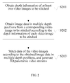
- the method includes: obtaining depth information of at least two video images to be stitched; obtaining image data in multiple depth positions from a corresponding video image to be stitched according to the depth information of each video image to be stitched; and stitching data of the video images according to the obtained image data in multiple depth positions, and generating 3D panoramic video streams.
- Another objective of the present invention is to provide a 3D panoramic videoconference method.
- the method includes: obtaining video streams of the same site synchronously from at least two viewpoints; obtaining image data in multiple depth positions from a corresponding video stream according to depth information of each video stream; stitching the video streams obtained from different viewpoints according to the depth information, and generating 3D panoramic video streams; and displaying video images of the 3D panoramic video streams on a terminal display according to a type of the terminal display.
- the device includes: a depth information obtaining apparatus, configured to obtain depth information of at least two video images to be stitched; a hierarchical image obtaining apparatus, configured to obtain image data in multiple depth positions from a corresponding video image to be stitched according to the depth information of each video image to be stitched; and a 3D panoramic video stream generating apparatus, configured to stitch data of the video images according to the obtained image data in multiple depth positions, and generate 3D panoramic video streams.
- the device includes: a depth information obtaining apparatus, configured to obtain video streams of the same site synchronously from at least two viewpoints; a hierarchical image obtaining apparatus, configured to obtain image data in multiple depth positions from a corresponding video stream according to depth information of each video stream; a 3D panoramic video stream generating apparatus, configured to stitch the video streams obtained from different viewpoints based on the depth information, and generate 3D panoramic video streams; and a video image display apparatus, configured to display video images of the 3D panoramic video streams on a terminal display according to a type of the terminal display.
- the embodiments of the present invention bring at least the following benefits:
- the technical solution of the present invention implements fast and real-time stitching of video images, simplifies the stitching of video images, improves efficiency of stitching video images, provides users with 3D panoramic seamless conferences of better luminance and hue effects, and enables the users to enjoy more advanced and authentic experience than the traditional telepresence.
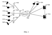
- the embodiments of the present invention put forward a multi-site, 2D/3D/multi-layer, and multi-viewpoint videoconference system based on depth cameras.
- a site A includes: depth cameras (101A, 102A), a videoconference server 103A, and terminal display devices (104A, 105A).
- the depth cameras (101A, 102A) are connected to the terminal display devices (104A, 105A) through the videoconference server 103A, and the terminal display devices (104A, 105A) may be 2D displays, 3D displays, or multi-layer displays.
- a site B includes: depth cameras (111B, 112B), and a server 113B which is connected to the depth cameras (111B, 112B).
- a site C includes: depth cameras (121C, 122C), and a server 123C which is connected to the depth cameras (121C, 122C).
- a site D includes: depth cameras (131D, 132D), and a server 133D which is connected to the depth cameras (131D, 132D).
- the server 103A is connected to the servers (113B, 123C, 133D) through a network 142 and a transmission device 141.
- the network 142 may be a cabled network, Internet, or satellite network.
- the method for generating 3D panoramic video streams includes the following steps:
- the depth cameras (111B, 112B) obtain video streams of the site B and depth information of each image from two viewpoints synchronously, and obtain depth images in different depth positions according to the depth information of the images.
- the image stitching is performed only once; for persons and objects that are moving, it is necessary to stitch each frame in real time.
- the areas with a little change of depth refer to: fixed furniture in a conference scene, videoconference devices which are in a fixed position (for example, cameras, wide-screen display devices, and printers). Such areas remain unchanged basically, and the depth position seldom or never changes. In this way, the areas with a little change of depth are retrieved beforehand by means of depth cameras, and two camera videos are stitched seamlessly.
- the areas with sharp change of depth generally refer to moving persons or objects (such as chairs). Participants generally have movements, and the chairs move along with the movements. If a person (without stretching arms) moves sharply relative to the camera, the depth position of the person reflected in the time axis changes sharply. However, in the images taken by different cameras at the same time, the person is in the same depth. Therefore, it is easy to stitch images seamlessly through a traditional image stitching technology. If a person (stretching arms) moves sharply relative to the camera, the person is not in the same depth position in the images taken by different cameras at the same time, which leads to different depth positions/parallax.
- the non-person image data is stitched to generate stitched non-person image data; the person image data is stitched to generate stitched person image data; and the stitched person image data is bonded to the stitched non-person image data to generate 3D panoramic video streams.
- an image change region of data of each person image in a current frame compared with data of a corresponding person image in a previous frame of each video stream may be detected. If the image change region is greater than a set threshold, only the person image data in the change region needs to be stitched.
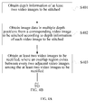
- background video image data and foreground image data are obtained from the corresponding video image according to the depth information of each video image.
- the obtained background image data is stitched to generate background panoramic image data;
- the obtained foreground image data is stitched to generate stitched foreground image data;
- the stitched foreground image data is bonded to the background panoramic image data to generate 3D panoramic video streams.
- the video image change region of foreground image data in the current frame compared with foreground image data in the previous frame of each video stream may be detected. If the video image change region is greater than a set threshold, only the foreground image data in the change region needs to be stitched.
- the person image data (306, 307) and the non-person image data (303, 304) are obtained from the video images (301, 302) according to the depth information of the images; the non-person image data (303, 304) is stitched to generate stitched non-person image data (305); the person image data (306, 307) is stitched to generate stitched person image data (308); and the stitched person image data (308) is bonded to the stitched non-person image data (305) to generate a synthesized video image (309), which is then coded and output.
- the technical solution provided in this embodiment of the present invention implements fast and real-time stitching of video images, simplifies the stitching of video images, improves efficiency of stitching video images, provides users with 3D panoramic seamless high-resolution conferences, enables the users to enjoy more advanced and authentic experience than the traditional telepresence, and overcomes ghosts caused by parallax in multi-viewpoint video stitching, especially when the close-shot parallax is noticeable.
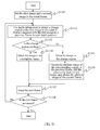
- FIG. 4 is a flow chart of a method for generating 3D panoramic video streams according to Embodiment 2 of the present invention. The method includes the following steps:
- the matched feature points of every two adjacent video images may be obtained in different methods such as Harris feature point detection method, Smallest Univalue Segment Assimilating Nucleus (SUSAN) feature point detection method, wavelet-based feature point detection method, and Scale-Invariant Feature Transformation (SIFT) feature point detection method.
- Harris feature point detection method Smallest Univalue Segment Assimilating Nucleus (SUSAN) feature point detection method
- wavelet-based feature point detection method wavelet-based feature point detection method
- SIFT Scale-Invariant Feature Transformation
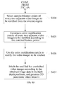
- the color rectification matrix needs to be generated only once. If color rectification needs to be performed for different video images to be stitched later, it is necessary only to perform step S406 directly without repeating steps S403 to S405.
- steps S403 to S405 may occur before step S401 to obtain the color rectification matrix.
- This embodiment can provide users with high-definition 3D panoramic seamless conferences, and can provide panoramic video streams of good luminance and hue by rectifying the color of the video images.
- the histogram rectification in the prior art can rectify the deviation of luminance and hue
- the prerequisite of rectifying the luminance and hue of the video images through a histogram is that the video images are very similar to each other. Therefore, in a scene of taking images from multiple viewpoints, when video images overlap each other to a small extent or do not overlap at all, the rectification deteriorates or fails due to sharp difference between the video images.
- the rectification using a histogram takes a long time because real-time statistics and rectification needs to be performed on each image.
- an overlap region between two adjacent images is required only at the time of calculating the color rectification matrix.
- color rectification can be performed through the color rectification matrix no matter whether any overlap region exists between the video images.
- the color rectification matrix needs to be generated only once, which saves time of rectifying the color of video images.
- This embodiment shows a process of rectifying video images taken by two cameras.
- an overlap region needs to exist between two video images taken by the two cameras.
- the subsequent rectification for two non-adjacent video images through the color rectification matrix no overlap region is required between the two non-adjacent video images taken by the two cameras, but an overlap region needs to exist between two adjacent video images.
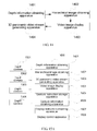
- FIG. 5 is a flow chart of a color rectification method according to Embodiment 3 of the present invention. The method includes the following steps:
- the two cameras are a source camera and a destination camera respectively, where the source camera takes a source video image, and the destination camera takes a destination video image, and the color of the source video image needs to be rectified as consistent with the color of the destination image.
- positions of the two cameras may be adjusted to generate the overlap region between the source video image and the destination video image regardless of the size of the overlap region.
- this embodiment does not limit the size of the overlap region.
- the preprocessing of the video images includes generally applied smooth denoising and distortion rectification. This step is optional.
- Color space transformation may be performed for the video images taken by the cameras.
- the video images before and after the transformation may be in one of the following formats: Red Green Blue (RGB), HSV, YUV, HSL, CIE-Lab, CIE-Luv, CMY, CMYK, and XYZ.
- the feature points may be obtained from the two video images in different methods such as Harris feature point detection method, SUSAN feature point detection method, wavelet-based feature point detection method, and SIFT feature point detection method.
- a SIFT algorithm is applied in this embodiment, which is characterized by being invariant in the case of spin, zoom and luminance change, and being stable to some extent in the case of viewpoint change, affine transformation, and noise.
- the matched feature points in the overlap region of the two video images may be obtained through other algorithms, and the obtaining method is not limited herein.
- the matched feature points in the overlap region may be selected in one of the following four modes:
- the SIFT feature point detection is the most commonly used mode of image processing in the prior art. Affine projection, luminance and hue keep unchanged by means of the SIFT feature point detection. It should be noted that other feature point detection modes in the prior art such as Harris detection, SUSAN detection, and improvements of them are also applicable so long as they can detect the feature points from the overlap region.
- unmatched feature points may be eliminated through a RANdom SAmple Consensus (RANSAC) method, and the remaining feature points are stable and reliable.
- RANSAC RANdom SAmple Consensus
- the method of eliminating the unmatched feature points is covered in the prior art (such as a method based on probability statistics), and is not limited herein.
- Mode 2 Detect SIFT feature points in the overlap region, and match the detected feature points to obtain multiple pairs of matched feature points of two adjacent video images. Find regions of the same area by pivoting on the matched feature points, and assign the mean value of the color features of the found regions to the matched feature points.
- each matched point For each pair of matched feature points, it is appropriate to find regions of the same area by pivoting on each of the pair of feature points, and use the regions as matched regions of the two video images.
- the mean value of color paths of the matched regions is used as a color value of the feature points.
- each matched point For example, for video images in an HSL format (H represents hue, S represents saturation, and L represents lightness), each matched point has corresponding H value, S value, and L value.
- a matched region is made up of points.
- the mean value of H values of all points in the region is H'
- the mean value of S values of all points in the region is S'
- the mean value of L values of all points in the region is L'. Values H', S', and L' are assigned to the matched feature points.
- Mode 3 Split the overlap region of the two video images, use the corresponding regions in the split overlap region of the two video images as matched feature points, and assign the mean value of color features of the corresponding regions to the matched feature points.
- each region After the overlap region is split, several pairs of matched regions with different areas exist in the split overlap region of the two video images, and each region includes several feature points.
- the mean value of color paths of each region is assigned to the feature points.
- the process of averaging the color paths of each region is similar to that described in mode 2 above. After the mean value of color paths is calculated for the matched regions, several matched feature points are obtained.
- Mode 4 Receive region blocks which are manually selected from the overlap region, use the corresponding selected region blocks of the two video images as matched feature points, and assign the mean value of color features of the corresponding region blocks to the matched feature points.
- Mode 4 differs from mode 3 in that: In mode 3, an image rectifying apparatus may split the overlap region automatically in a preset mode; in mode 4, several matched regions are selected manually from the overlap region, and then the selected results are input into the image rectifying apparatus for subsequent processing.
- “Mat_dst” is the color space matrix of the destination video image
- “Mat_src” is the color space matrix of the source video image.
- the first row of “Mat_dst” represents the first point among m points
- "hl l” is the hue value of the first point
- "s12” is the saturation value of the first point
- "113” is the luminance value of the first point. Therefore, “Mat_dst” is a matrix of H, S and L values of m destination pixel points of a destination video image in m matched points.
- the Mat_ColorRectify is the calculated color rectification matrix.
- the calculated color rectification matrix can be applied to rectify color no matter how the source camera and the destination camera change their positions, and whether the taken video images are intersected.
- the color rectification process is as follows:
- a color space matrix of the video image to be rectified is generated. It is assumed that the video image to be rectified changes to the HSL format after the color space transformation, and this video image is made up of Y pixel points. Therefore, the color space matrix is a (Y*3) matrix, and each row of the matrix represents the H value, S value, and L value of a pixel point.
- the Mat ColorRectify is multiplied by the color space matrix of the video image to be rectified, a multiplication result is used as a color space matrix of the rectified video image, and the rectified video image is generated according to the color space matrix of the rectified video image.
- color rectification is performed for video images.
- the overlap region between two adjacent images is required only at the time of calculating the color rectification matrix.
- color rectification can be performed through the color rectification matrix no matter whether any overlap region exists between the video images.
- the color rectification matrix needs to be generated only once, which saves time of rectifying color of the video images.
- This embodiment shows a process of rectifying video images taken by N cameras.
- an overlap region needs to exist between video images taken by every two adjacent cameras. All N-1 pairs of video images are input, where images in each pair are adjacent to each other; and N-1 color rectification matrices are generated.
- no overlap region is required between the images taken by the N cameras.
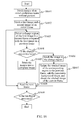
- FIG. 6 is a flow chart of a color rectification method provided in Embodiment 4 of the present invention. The method includes the following steps:
- Every two adjacent cameras in the N cameras make up a pair.
- camera 1 and camera 2 make up a pair
- camera 2 and camera 3 make up a pair
- camera N-1 and camera N make up a pair.
- the two cameras in each pair are a source camera and a destination camera respectively, where the source camera takes a source video image, and the destination camera takes a destination video image.
- the positions of the N cameras may be adjusted to generate an overlap region between the source video image and the destination video image taken by each pair of adjacent cameras, regardless of the size of the overlap region.
- this embodiment does not limit the size of the overlap region.
- the preprocessing of the video images includes generally applied smooth denoising and distortion rectification. This step is optional, and is covered in the prior art.
- the video images taken by the cameras are in the RGB format. Color space transformation may be performed for the RGB images.
- the transformed video images may be in one of the following formats: HSV, YUV, HSL, CIE-Lab, CIE-Luv, CMY, CMYK, and XYZ.
- step 304 the process of obtaining the matched feature points of the N-1 pairs of adj acent video images is similar to step 204 in the previous embodiment.
- This step is similar to S505 in the previous embodiment.
- Step S604 to step S607 are a process of processing one of N-1 pairs of adjacent video images. This process is the same as step S504 to step S507 described in Embodiment 3 above.
- step S608 Judge whether all the N-1 pairs of video images are processed; if all the N-1 pairs of video images are processed, proceed to step S609; if not all the N-1 pairs of video images are processed, return to step S604.
- N-1 color rectification matrices have been calculated out. It is assumed that the first pair of video images corresponds to the first color rectification matrix (Mat_1), and the second pair of video images corresponds to the second color rectification matrix (Mat_2), and by analogy, pair N-1 corresponds to color rectification matrix N-1 (Mat_N-l).
- Mat_(k) is multiplied by the color space matrix of the video image to be rectified, the multiplication result is used as a color space matrix of the rectified video image, and the rectified video image is generated according to the color space matrix of the rectified video image.
- color rectification is performed for the video images.
- the overlap region between two adjacent images is required only at the time of calculating the color rectification matrix.
- color rectification can be performed through the color rectification matrix no matter whether any overlap region exists between the video images.
- the color rectification matrix needs to be generated only once, which saves time of rectifying color of the video images.
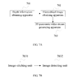
- FIG. 7A shows a structure of a device for generating 3D panoramic video streams according to Embodiment 5 of the present invention.
- the device includes: a depth information obtaining apparatus 701, configured to obtain depth information of at least two video images to be stitched; a hierarchical image obtaining apparatus 702, configured to obtain image data in multiple depth positions from a corresponding video image to be stitched according to the depth information of each video image to be stitched; and a 3D panoramic video stream generating apparatus 703, configured to stitch data of the video images according to the obtained image data in multiple depth positions, and generate 3D panoramic video streams.
- a depth information obtaining apparatus 701 configured to obtain depth information of at least two video images to be stitched
- a hierarchical image obtaining apparatus 702 configured to obtain image data in multiple depth positions from a corresponding video image to be stitched according to the depth information of each video image to be stitched
- a 3D panoramic video stream generating apparatus 703 configured to stitch data of the video images according to the obtained image data
- the depth cameras (111B, 112B) obtain video streams of the site B and depth information of each image from two viewpoints synchronously, and obtain depth images in different depth positions according to the depth information of the image.
- the image stitching is performed once; for persons and objects that are moving, it is necessary to stitch each frame in real time.
- the hierarchical image obtaining apparatus 702 obtains person image data from a corresponding video image according to the depth information of each video image, and obtains non-person image data from the corresponding video image according to the depth information of each video image.
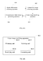
- the 3D panoramic video stream generating apparatus 703 includes an image stitching unit 7031 and an image detecting unit 7032.
- the image stitching unit 7031 stitches non-person image data to generate stitched non-person image data, stitches person image data to generate stitched person image data, and bonds the stitched person image data to the stitched non-person image data to generate 3D panoramic video streams.
- the image detecting unit 7032 detects an image change region of data of each person image in the current frame compared with data of this person image in the previous frame of each video stream; if it is determined that the image change region is less than a set threshold, the image stitching unit 7031 stitches only the person image data in the image change region.
- the hierarchical image obtaining apparatus 702 obtains foreground image data from the corresponding video image according to the depth information of each video image, and obtains background image data from the corresponding video image according to the depth information of each video image.
- the 3D panoramic video stream generating apparatus 703 includes an image stitching unit 7031 and an image detecting unit 7032.
- the image stitching unit 7031 stitches the obtained background image data to generate background panoramic image data, stitches the obtained foreground image data to generate stitched foreground image data, and bonds the stitched foreground image data to the background panoramic image data to generate 3D panoramic video streams.
- the image detecting unit 7032 detects the video image change region of the foreground image data in the current frame compared with the foreground image data in the previous frame of each video stream; if it is determined that the image change region is less than a set threshold, the image stitching unit 7031 stitches only the foreground image data in the image change region.
- the technical solution provided in this embodiment of the present invention implements fast and real-time stitching of video images, simplifies the stitching of video images, improves efficiency of stitching video images, provides users with 3D panoramic seamless high-resolution conferences, enables the users to enjoy more advanced and authentic experience than the traditional telepresence, and overcomes ghosts caused by parallax in multi-viewpoint video stitching, especially when the close-shot parallax is noticeable.
- FIG. 8A shows a structure of a device for generating 3D panoramic video streams according to Embodiment 6 of the present invention.
- the device includes a depth information obtaining apparatus 801, a hierarchical image obtaining apparatus 802, a video image rectifying apparatus 803, and a 3D panoramic video stream generating apparatus 804.
- the depth information obtaining apparatus 801 and the hierarchical image obtaining apparatus 802 are similar to those described in Embodiment 5 above.
- the video image rectifying apparatus 803 includes an obtaining unit 8031, a selecting unit 8032, a generating unit 8033, and a rectifying unit 8034 (as shown in FIG. 8B ).
- the obtaining unit 8031 is configured to obtain at least two video images to be rectified, where an overlap region exists between every two adjacent video images among the at least two video images to be rectified.
- the obtaining unit 8031 may be a videorecording device such as videorecorder and camera.
- the selecting unit 8032 is configured to select matched feature points of every two adjacent video images to be rectified from the overlap region.
- the selecting unit 8032 may be a processor-specific chip capable of extracting and matching feature points of images, or a universal processor chip, and works based on an algorithm for extracting and matching feature points of images.
- the generating unit 8033 is configured to generate a color rectification matrix of every two adjacent video images to be rectified according to the matched feature points.
- the generating unit 8033 may be a Complex Programmable Logic Device (CPLD) capable of processing matrices, or a Field Programmable Gate Array (FPGA).
- the rectifying unit 8034 is configured to use the color rectification matrix to rectify the received video images to be stitched.
- CPLD Complex Programmable Logic Device
- FPGA Field Programmable Gate Array
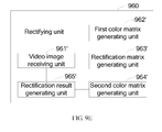
- FIG. 9B shows a video image rectifying apparatus according to Embodiment 2 of the present invention.
- the apparatus includes an obtaining unit 910, a preprocessing unit 920, a transforming unit 930, a selecting unit 940, a generating unit 950, and a rectifying unit 960.
- the obtaining unit 910 is configured to obtain at least two video images to be rectified, where an overlap region exists between every two adjacent video images among the at least two video images to be rectified.
- the obtaining unit 910 may be a videorecording device such as videorecorder and camera.
- the preprocessing unit 920 is configured to preprocess at least two video images to be rectified after the obtaining unit obtains the at least two video images to be rectified.
- the preprocessing includes smooth denoising and/or distortion rectification.
- the preprocessing unit 920 is optional.
- the transforming unit 930 is configured to perform color space transformation for the at least two video images to be rectified.
- the video images to be rectified before and after the transformation may be in one of the following formats: RGB, HSV, YUV, HSL, CIE-Lab, CIE-Luv, CMY, CMYK, and XYZ.
- the selecting unit 940 is configured to select matched feature points of every two adjacent video images to be rectified from the overlap region.
- the generating unit 950 is configured to generate a color rectification matrix of every two adjacent video images to be rectified according to the matched feature points.
- the rectifying unit 960 is configured to use the color rectification matrix to rectify the received video images to be stitched.
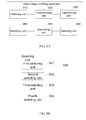
- the selecting unit 940 includes at least one of the following units: a first selecting unit 941, configured to detect SIFT feature points in the overlap region, and match the detected feature points to obtain multiple pairs of matched feature points of the two adjacent video images to be rectified; a second selecting unit 942, configured to: detect SIFT feature points in the overlap region, match the detected feature points to obtain multiple pairs of matched feature points of two adjacent video images to be rectified, find regions of the same area by pivoting on the matched feature points, and assign the mean value of the color features of the found regions to the matched feature points; a third selecting unit 943, configured to: split the overlap region of the two video images, use the corresponding regions in the split overlap region of the two video images to be rectified as matched feature points, and assign the mean value of color features of the corresponding regions to the matched feature points; and a fourth selecting unit 944, configured to receive region blocks which are manually selected from the overlap region, use the corresponding selected region blocks of the two video images to
- the generating unit 950 may include: a color matrix creating unit 951, configured to create a color space matrix of the source video image and a color space matrix of the destination video image, where each row of the color space matrix represents color space attributes of one of the matched feature points; a transformation relation establishing unit 952, configured to establish a matrix transformation relation between the color space matrix of the source video image and the color space matrix of the destination video image, where transformation relation is: the color space matrix of the source video image is multiplied by the color rectification matrix, and a multiplication result plus an error amount is the color space matrix of the destination video image; and a rectification matrix calculating unit 953, configured to calculate the color rectification matrix when the error amount is the smallest according to the transformation relation.
- the rectifying unit 960 may include: a video image receiving unit 961, configured to receive a video image to be rectified from an inputting apparatus which inputs a source video image, for example, receive a video image to be stitched; a color matrix generating unit 962, configured to generate a color space matrix of the video image to be rectified; a color matrix transforming unit 963, configured to multiply the color rectification matrix by the color space matrix of the video image to be rectified, and use the multiplication result as a color space matrix of the rectified video image; and a rectification result generating unit 964, configured to generate the rectified video image according to the color space matrix of the rectified video image.
- a video image receiving unit 961 configured to receive a video image to be rectified from an inputting apparatus which inputs a source video image, for example, receive a video image to be stitched
- a color matrix generating unit 962 configured to generate a color space matrix of the video image to be rectified
- the obtaining unit 910 obtains N video images to be rectified that are adjacent in tandem, where N is a natural number greater than 2, the N video images include N-1 pairs of adjacent video images to be rectified, and each pair of video images to be rectified corresponds to a color rectification matrix.
- the rectifying unit 660 may include: a video image receiving unit 961', configured to receive a video image to be rectified from an inputting apparatus, where the video image to be rectified is a video image K among the N video images; a first color matrix generating unit 962', configured to generate a color space matrix of the video image to be rectified; a rectification matrix generating unit 963', configured to multiply color rectification matrix 1 to color rectification matrix K-1 in tandem to generate a color rectification matrix of the video image to be rectified; a second color matrix generating unit 964', configured to multiply the color rectification matrix by the color space matrix of the video image to be rectified, and use the multiplication result as the color space matrix of the rectified video image; and a rectification result generating unit 965, configured to generate the rectified video image according to the color space matrix of the rectified video image.
- a video image receiving unit 961' configured to receive a video image to be rectified from an inputting apparatus, where the video image
- the following describes a color rectification process put forward in this embodiment in a scenario that five cameras transmit five adjacent video images. It is assumed that the five video images are F1, F2, F3, F4, and F5, every two adjacent video images make up a pair, namely, F 1 and F2 make up a pair which is represented by Z1, F2 and F3 make up a pair which is represented by Z2, F3 and F4 make up a pair which is represented by Z3, and F4 and F5 make up a pair which is represented by Z4.
- the color rectification matrices are calculated out according to step S504 to step S507 according to Embodiment 3 above.
- the color rectification matrix of Z1 is Mat_1
- the color rectification matrix of Z2 is Mat_2
- the color rectification matrix of Z3 is Mat_3
- the color rectification matrix of Z4 is Mat_4.
- color rectification matrix 1 to color rectification matrix K-1 can be multiplied to generate the color rectification matrix of the video image input by a camera K
- FIG. 10 is a flow chart of a 3D panoramic videoconference method according to Embodiment 7 of the present invention. The method includes the following steps:
- FIG. 11 is a video stitching flow chart according to Embodiment 7 of the present invention.
- the video stitching process includes the following steps:
- the image sequences are generally correlated with each other, and the region that changes is only a part of the scene. Therefore, this algorithm simplifies the calculation of video stitching significantly. In this way, a complex algorithm may be applied to video stitching, and an accurate stitched panoramic video can be obtained when the videos are stitched in real time.
- the change region is calculated by comparing the current frame with the previous frame.
- the change region may be calculated by comparing the current frame with the initial frame.
- the cameras shown in FIG. 1 can be used to obtain the first image sequence and the second image sequence shown in FIG. 12 .
- a video sequence is a result of stitching an image in the first image sequence with a corresponding image in the second image sequence, obtaining a stitched image of each image pair, performing 3D coding for the stitched image, and outputting the coded image.
- the display type of a terminal is determined.
- the terminal displays 2D image information of the synthesized video image; if the display device of the terminal is a 3D display, the terminal displays 3D image information of the synthesized video image; and, if the display device of the terminal is a multi-layer display, the terminal displays image information in multiple depth positions of the synthesized video image.
- This embodiment of the present invention provides users with high-resolution 3D panoramic seamless conferences, overcomes ghosts caused by parallax in multi-viewpoint video stitching, especially when the close-shot parallax is noticeable, and enables different display modes for different display devices.
- a multi-layer display can be used to display the foreground and the background respectively and offer good 3D experience.
- a 3D display or 2D display can be used to offer better 3D presence of higher precision.
- FIG. 13 is a flow chart of a 3D panoramic videoconference method according to Embodiment 8 of the present invention. The method includes the following steps:
- the color rectification matrix needs to be generated only once. If color rectification needs to be performed for different video images to be stitched later, it is necessary only to perform step S1306 directly without repeating steps S1303 toS1305.
- steps S1303 to S1305 may occur before step S1301 to obtain the color rectification matrix.
- FIG. 14 shows a structure of a 3D panoramic videoconference device according to Embodiment 9 of the present invention.
- the device includes: a depth information obtaining apparatus 1401, configured to obtain video streams of the same site synchronously from at least two viewpoints; a hierarchical image obtaining apparatus 1402, configured to obtain image data in multiple depth positions from a corresponding video stream according to depth information of each video stream; a 3D panoramic video stream generating apparatus 1403, configured to stitch the video streams obtained from different viewpoints based on the depth information, and generate 3D panoramic video streams; and a video image display apparatus 1404, configured to display video images of the 3D panoramic video streams on a terminal display according to a type of the terminal display.
- depth cameras (1501, 1502, 1503, 1504) are connected to a 3D panoramic videoconference device 1400, and the depth information obtaining apparatus 1401 receives video streams obtained from four viewpoints of the same site synchronously.
- the hierarchical image obtaining apparatus 1402 obtains image data in multiple depth positions from a corresponding video stream according to depth information of each video stream.
- the 3D panoramic video stream generating apparatus 1403 stitches the video streams obtained from different viewpoints based on video image depth information, obtains a stitched 3D video sequence, encodes the stitched 3D video sequence, and generates 3D panoramic video streams.
- the video image display apparatus 1404 is configured to display video images of the 3D panoramic video streams on a terminal display according to a type of the terminal display.
- the 3D panoramic videoconference device 1400 further includes a gesture instruction storing apparatus 1505, which is configured to store a mapping relation between gesture information and display control instructions; a display instruction obtaining apparatus 1506, which is configured to obtain the display control instruction corresponding to the obtained gesture information according to the mapping relation; a display instruction obtaining apparatus 1507, which is configured to obtain the display control instruction corresponding to the obtained gesture information according to the mapping relation; and a display control apparatus 1508, which is configured to control display activities of the terminal display according to the obtained display control instruction.
- a gesture instruction storing apparatus 1505 which is configured to store a mapping relation between gesture information and display control instructions
- a display instruction obtaining apparatus 1506 which is configured to obtain the display control instruction corresponding to the obtained gesture information according to the mapping relation
- a display instruction obtaining apparatus 1507 which is configured to obtain the display control instruction corresponding to the obtained gesture information according to the mapping relation
- a display control apparatus 1508 which is configured to control display activities of the terminal display according to the obtained display control instruction.
- the video image display apparatus 1404 includes a display type determining unit 14041 and a display 14042.
- the display 14042 includes a 2D display, or a 3D display, or a multi-layer display.
- the display type determining unit 14041 determines that the terminal display is a 2D display, 3D display, or multi-layer display
- the terminal displays the 2D image information of synthesized video images
- the display 14042 is a 3D display
- the terminal displays the 3D image information of synthesized video images
- the display 14042 is a multi-layer display
- the terminal displays the image information in multiple depth positions of synthesized video images.
- a fast video stitching method disclosed in this embodiment of the present invention includes the following steps:
- the stitched panoramic image is encoded in a 3D mode and output.
- the display type of the terminal is determined. If the display device of the terminal is a 2D display, the terminal displays 2D image information of the synthesized video image; if the display device of the terminal is a 3D display, the terminal displays 3D image information of the synthesized video image; and, if the display device of the terminal is a multi-layer display, the terminal displays image information in multiple depth positions of the synthesized video image.
- This embodiment of the present invention provides users with high-resolution 3D panoramic seamless conferences, overcomes ghosts caused by parallax in multi-viewpoint video stitching, especially when the close-shot parallax is noticeable, and enables different display modes for different display devices.
- a multi-layer display can be used to display the foreground and the background respectively and offer good 3D experience.
- a 3D display or 2D display can be used to offer better 3D presence of higher precision.
- a more user-friendly data coordination mode is put forward, and therefore, the effects of gesture instructions sent by different persons on different sites are displayed on the same display device, and different persons of different sites have the experience of controlling the data and the conference system in the same site position.
- depth cameras are applied to facilitate remote terminal data coordination and conference control of the videoconference or telepresence conference system.
- Hands, fingers and palms can be recognized according to the depth cameras, and the instructions indicated by the human hand can be recognized.
- the gesture identification includes the following steps:
- the data in sites B, C, D, and E is displayed on the display for displaying data of site A simultaneously.
- a data content display mode of the site B can be controlled using gestures.
- Data content display modes of the site C, site D, and site E can also be controlled using gestures.
- Persons in the site A use gestures to control the data content displayed on the site C, and watch desired contents.
- Gestures for controlling the data display mode remotely may be defined herein, so as to control and display conference data content between different sites in a friendly way.
- the gestures may be common gesture models applied to the local site.
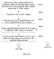
- mapping relation between the gesture and the display control instruction may be defined as:
- an upright forefinger is a signal of displaying the data of the first site and spotlighting the data of the first site.
- an upright forefinger and an upright middle finger are a signal of displaying the data of the second site and spotlighting the data of the second site.
- an upright middle finger, an upright ring finer, and an upright little finger are a signal of displaying the data of the third site and spotlighting the data of the third site; if all fingers of a hand are upright except the thumb, it is a signal of displaying the data of the fourth site and spotlighting the data of the fourth site; if the thumb is fixed but other fingers spin, it is a signal of displaying the data of the fifth site, sixth site..., in turn, and spotlighting the data of the site indicated when the spin stops; when a person stretch his palm, put up the arm upright and pull the arm back to chest, it is a signal of displaying the data of the spotlighted site in full screen.
- the mapping relation between the gesture information and the display control instruction is stored, the depth cameras photograph the human gestures in the sites and generate gesture information, the display control instruction corresponding to the gesture information is found according to the mapping relation, and the display of the terminal display device is controlled according to the obtained display control instruction.
- the display device of the terminal is a 2D display, the terminal displays 2D image information of the synthesized video image; if the display device of the terminal is a 3D display, the terminal displays 3D image information of the synthesized video image; and, if the display device of the terminal is a multi-layer display, the terminal displays image information in multiple depth positions.
- the technical solution disclosed in this embodiment of the present invention provides users with 3D panoramic seamless high-resolution conferences, enables the users to enjoy more advanced and authentic experience than the traditional telepresence, overcomes ghosts caused by parallax in multi-viewpoint video stitching, especially when the close-shot parallax is noticeable, provides a fast real-time method of stitching videos, and simplifies video stitching and improves efficiency of video stitching.
- the technical solution enables different display modes for different display devices.
- a multi-layer display can be used to display the foreground and the background respectively and offer good 3D experience.
- a 3D display can be used to offer better 3D presence of higher precision.
- the technical solution also provides a more friendly data coordination mode. Therefore, the effects of gesture instructions sent by different persons on different sites are displayed on the same display device, and different persons of different sites have the experience of controlling the data and the conference system in the same site position.
- FIG. 21 shows a structure of a 3D panoramic videoconference device according to Embodiment 10 of the present invention.
- the device includes a depth information obtaining apparatus 2110, a hierarchical image obtaining apparatus 2120, a video image rectifying apparatus 2130, a 3D panoramic video stream generating apparatus 2140, and a video image display apparatus 2150.
- the depth information obtaining apparatus 2110, the hierarchical image obtaining apparatus 2120, and the video image display apparatus 2150 are similar to those described Embodiment 9 above.
- the video image rectifying apparatus 2130 is configured to rectify color of the video streams obtained by the depth information obtaining apparatus 2110.
- the video image rectifying apparatus 2130 is connected to the hierarchical image obtaining apparatus 2120, and performs color rectification after the image data in a depth position of the video stream is obtained. Nevertheless, it is also practicable to obtain the image data in a depth position of the video stream after the color of the video stream is rectified.
- the video image rectifying apparatus 2130 includes an obtaining unit 2131, a selecting unit 2132, a generating unit 2133, and a rectifying unit 2134, which are connected in tandem.
- the obtaining unit 2131 is configured to obtain at least two video images to be rectified, where an overlap region exists between every two adjacent video images among the at least two rectified video images.
- the selecting unit 2132 is configured to select matched feature points of every two adjacent video images to be rectified from the overlap region.
- the generating unit 2133 is configured to generate a color rectification matrix of every two adjacent video images to be rectified according to the matched feature points.
- the rectifying unit 2134 is configured to use the color rectification matrix to rectify the video stream.
- the color rectification for the video stream in this embodiment depends on the color rectification matrix generated by the generating unit 2133.
- the color rectification matrix may be generated after the hierarchical image obtaining apparatus 2120 obtains the image data in the depth position of the video stream, or generated before the video stream is obtained.
- video streams can be rectified only by using the color rectification matrix generated beforehand.
- the 3D panoramic video stream generating apparatus 2140 is configured to stitch the rectified video streams obtained from different viewpoints based on the depth information, and generate 3D panoramic video streams.
- This embodiment not only brings benefits of Embodiment 9, but also performs color rectification for the video images so that the users can have a panoramic videoconference of good luminance and hue.
- an overlap region between two adjacent images is required only at the time of calculating the color rectification matrix.
- color rectification can be performed through the color rectification matrix no matter whether any overlap region exists between the video images.
- the color rectification matrix needs to be generated only once, which saves time of rectifying color of video images.
- the software product may be stored in storage media such as ROM/RAM, magnetic disk, or CD-ROM, and incorporates several instructions that make a computer device (for example, a personal computer, a server, or a network device) execute the methods specified in any embodiment of the present invention or part of the embodiment.
- a computer device for example, a personal computer, a server, or a network device
Landscapes
- Engineering & Computer Science (AREA)
- Multimedia (AREA)
- Signal Processing (AREA)
- General Engineering & Computer Science (AREA)
- Image Processing (AREA)
- Two-Way Televisions, Distribution Of Moving Picture Or The Like (AREA)
Applications Claiming Priority (3)
| Application Number | Priority Date | Filing Date | Title |
|---|---|---|---|
| CN200810247531A CN101771830B (zh) | 2008-12-30 | 2008-12-30 | 立体全景视频流生成方法、设备及视频会议方法和设备 |
| CN2009101186295A CN101820550B (zh) | 2009-02-26 | 2009-02-26 | 多视点视频图像校正方法、装置及系统 |
| PCT/CN2009/075383 WO2010075726A1 (zh) | 2008-12-30 | 2009-12-08 | 立体全景视频流生成方法、设备及视频会议方法和设备 |
Publications (2)
| Publication Number | Publication Date |
|---|---|
| EP2385705A1 true EP2385705A1 (de) | 2011-11-09 |
| EP2385705A4 EP2385705A4 (de) | 2011-12-21 |
Family
ID=42309794
Family Applications (1)
| Application Number | Title | Priority Date | Filing Date |
|---|---|---|---|
| EP09836013A Ceased EP2385705A4 (de) | 2008-12-30 | 2009-12-08 | Verfahren und vorrichtung zur erzeugung eines stereoskopischen panoramavideostreams sowie verfahren und vorrichtung für videokonferenzen |
Country Status (3)
| Country | Link |
|---|---|
| US (1) | US8717405B2 (de) |
| EP (1) | EP2385705A4 (de) |
| WO (1) | WO2010075726A1 (de) |
Cited By (3)
| Publication number | Priority date | Publication date | Assignee | Title |
|---|---|---|---|---|
| WO2013113373A1 (en) * | 2012-01-31 | 2013-08-08 | Sony Ericsson Mobile Communications Ab | Method and electronic device for creating a combined image |
| CN107360354A (zh) * | 2017-07-31 | 2017-11-17 | 广东欧珀移动通信有限公司 | 拍照方法、装置、移动终端和计算机可读存储介质 |
| EP3410387A4 (de) * | 2016-03-10 | 2019-01-23 | Sony Corporation | Informationsprozessor und informationsverarbeitungsverfahren |
Families Citing this family (72)
| Publication number | Priority date | Publication date | Assignee | Title |
|---|---|---|---|---|
| CN101984463A (zh) * | 2010-11-02 | 2011-03-09 | 中兴通讯股份有限公司 | 全景图合成方法及装置 |
| CN102075773B (zh) * | 2010-11-25 | 2014-05-07 | 深圳市创凯电子有限公司 | 立体与平面图像混合信号在超大屏幕上显像的同步方法 |
| WO2012117729A1 (ja) * | 2011-03-03 | 2012-09-07 | パナソニック株式会社 | 追体験映像を提供することができる映像提供装置、映像提供方法、映像提供プログラム |
| JP5863134B2 (ja) * | 2011-05-05 | 2016-02-16 | エンパイア テクノロジー ディベロップメント エルエルシー | レンチキュラ指向性ディスプレイ |
| ES2607214T3 (es) | 2011-05-31 | 2017-03-29 | Nokia Technologies Oy | Métodos, aparatos y productos de programa informático para generar imágenes panorámicas usando datos de mapas de profundidad |
| TWI449408B (zh) * | 2011-08-31 | 2014-08-11 | Altek Corp | 三維影像擷取方法與裝置及三維影像顯示裝置 |
| KR101917764B1 (ko) * | 2011-09-08 | 2018-11-14 | 삼성디스플레이 주식회사 | 입체 영상 표시 장치 및 입체 영상 표시 방법 |
| WO2013061334A1 (en) * | 2011-10-25 | 2013-05-02 | Mohan Devaraj | 3d stereoscopic imaging device with auto parallax |
| JP2013118468A (ja) * | 2011-12-02 | 2013-06-13 | Sony Corp | 画像処理装置および画像処理方法 |
| US10033942B1 (en) * | 2012-05-25 | 2018-07-24 | Altia Systems, Inc. | Real time video system with high dynamic range |
| US20130329985A1 (en) * | 2012-06-07 | 2013-12-12 | Microsoft Corporation | Generating a three-dimensional image |
| US9870504B1 (en) * | 2012-07-12 | 2018-01-16 | The United States Of America, As Represented By The Secretary Of The Army | Stitched image |
| KR102245648B1 (ko) | 2012-09-10 | 2021-04-29 | 에이매스, 아이엔씨. | 복수의 기기를 이용한 다차원의 환경 데이터 캡쳐 |
| US9058683B2 (en) * | 2013-02-21 | 2015-06-16 | Qualcomm Incorporated | Automatic image rectification for visual search |
| US9600703B2 (en) * | 2013-03-15 | 2017-03-21 | Cognex Corporation | Systems and methods for sorting image acquisition settings for pattern stitching and decoding using multiple captured images |
| RU2667605C2 (ru) | 2013-05-10 | 2018-09-21 | Конинклейке Филипс Н.В. | Способ кодирования сигнала видеоданных для использования с многовидовым устройством визуализации |
| EP2806401A1 (de) * | 2013-05-23 | 2014-11-26 | Thomson Licensing | Verfahren und Vorrichtung zur Verarbeitung eines Bildes |
| US20150002636A1 (en) * | 2013-06-28 | 2015-01-01 | Cable Television Laboratories, Inc. | Capturing Full Motion Live Events Using Spatially Distributed Depth Sensing Cameras |
| US10115033B2 (en) | 2013-07-30 | 2018-10-30 | Kodak Alaris Inc. | System and method for creating navigable views |
| WO2015026874A1 (en) | 2013-08-19 | 2015-02-26 | Nant Holdings Ip, Llc | Metric based recognition, systems and methods |
| US9686479B2 (en) | 2013-09-16 | 2017-06-20 | Duke University | Method for combining multiple image fields |
| TWI537767B (zh) * | 2013-10-04 | 2016-06-11 | 財團法人工業技術研究院 | 可調體感範圍之多人指引系統與其方法 |
| KR102265109B1 (ko) | 2014-01-24 | 2021-06-15 | 삼성전자주식회사 | 영상 처리 방법 및 장치 |
| US9742995B2 (en) | 2014-03-21 | 2017-08-22 | Microsoft Technology Licensing, Llc | Receiver-controlled panoramic view video share |
| WO2016015624A1 (en) * | 2014-07-28 | 2016-02-04 | Mediatek Inc. | Portable device capable of generating panoramic file |
| KR102332752B1 (ko) * | 2014-11-24 | 2021-11-30 | 삼성전자주식회사 | 지도 서비스를 제공하는 전자 장치 및 방법 |
| CN105812649B (zh) * | 2014-12-31 | 2019-03-29 | 联想(北京)有限公司 | 一种摄像方法和装置 |
| WO2016145625A1 (en) * | 2015-03-18 | 2016-09-22 | Xiaoou Tang | 3d hand pose recovery from binocular imaging system |
| US10242474B2 (en) | 2015-07-15 | 2019-03-26 | Fyusion, Inc. | Artificially rendering images using viewpoint interpolation and extrapolation |
| US10222932B2 (en) | 2015-07-15 | 2019-03-05 | Fyusion, Inc. | Virtual reality environment based manipulation of multilayered multi-view interactive digital media representations |
| US12261990B2 (en) | 2015-07-15 | 2025-03-25 | Fyusion, Inc. | System and method for generating combined embedded multi-view interactive digital media representations |
| US12495134B2 (en) | 2015-07-15 | 2025-12-09 | Fyusion, Inc. | Drone based capture of multi-view interactive digital media |
| US11006095B2 (en) | 2015-07-15 | 2021-05-11 | Fyusion, Inc. | Drone based capture of a multi-view interactive digital media |
| US10147211B2 (en) * | 2015-07-15 | 2018-12-04 | Fyusion, Inc. | Artificially rendering images using viewpoint interpolation and extrapolation |
| US11095869B2 (en) | 2015-09-22 | 2021-08-17 | Fyusion, Inc. | System and method for generating combined embedded multi-view interactive digital media representations |
| US10609438B2 (en) * | 2015-08-13 | 2020-03-31 | International Business Machines Corporation | Immersive cognitive reality system with real time surrounding media |
| EP3335418A1 (de) | 2015-08-14 | 2018-06-20 | PCMS Holdings, Inc. | System und verfahren für telepräsenz mit mehreren ansichten in der erweiterten realität |
| KR20170025058A (ko) | 2015-08-27 | 2017-03-08 | 삼성전자주식회사 | 영상 처리 장치 및 이를 포함하는 전자 시스템 |
| US11783864B2 (en) | 2015-09-22 | 2023-10-10 | Fyusion, Inc. | Integration of audio into a multi-view interactive digital media representation |
| CN106683071B (zh) * | 2015-11-06 | 2020-10-30 | 杭州海康威视数字技术股份有限公司 | 图像的拼接方法和装置 |
| KR101773929B1 (ko) * | 2016-02-29 | 2017-09-01 | (주)에프엑스기어 | 광 시야각 영상 처리 시스템, 광 시야각 영상의 전송 및 재생 방법, 및 이를 위한 컴퓨터 프로그램 |
| EP3223524A1 (de) * | 2016-03-22 | 2017-09-27 | Thomson Licensing | Verfahren, vorrichtung und strom aus der formatierung eines immersiven videos für alte und immersive wiedergabevorichtungen |
| US10762712B2 (en) | 2016-04-01 | 2020-09-01 | Pcms Holdings, Inc. | Apparatus and method for supporting interactive augmented reality functionalities |
| EP3249929A1 (de) | 2016-05-25 | 2017-11-29 | Thomson Licensing | Verfahren und netzwerkausrüstung zur erstellung eines manifestes |
| US11202017B2 (en) | 2016-10-06 | 2021-12-14 | Fyusion, Inc. | Live style transfer on a mobile device |
| KR102561860B1 (ko) | 2016-10-25 | 2023-08-02 | 삼성전자주식회사 | 전자장치 및 그 제어방법 |
| CN106534825B (zh) * | 2016-11-29 | 2018-09-07 | 宁波易维视显示技术有限公司 | 基于中线边缘特征投影的自动检测全景视频、图片的方法 |
| CN109983765A (zh) * | 2016-12-05 | 2019-07-05 | 惠普发展公司,有限责任合伙企业 | 经由全方位相机的视听传输调整 |
| US10038894B1 (en) * | 2017-01-17 | 2018-07-31 | Facebook, Inc. | Three-dimensional scene reconstruction from set of two dimensional images for consumption in virtual reality |
| US10437879B2 (en) | 2017-01-18 | 2019-10-08 | Fyusion, Inc. | Visual search using multi-view interactive digital media representations |
| US20180227482A1 (en) | 2017-02-07 | 2018-08-09 | Fyusion, Inc. | Scene-aware selection of filters and effects for visual digital media content |
| JP7159057B2 (ja) * | 2017-02-10 | 2022-10-24 | パナソニック インテレクチュアル プロパティ コーポレーション オブ アメリカ | 自由視点映像生成方法及び自由視点映像生成システム |
| US11184599B2 (en) * | 2017-03-15 | 2021-11-23 | Pcms Holdings, Inc. | Enabling motion parallax with multilayer 360-degree video |
| US11218683B2 (en) | 2017-03-22 | 2022-01-04 | Nokia Technologies Oy | Method and an apparatus and a computer program product for adaptive streaming |
| US10313651B2 (en) | 2017-05-22 | 2019-06-04 | Fyusion, Inc. | Snapshots at predefined intervals or angles |
| US11069147B2 (en) | 2017-06-26 | 2021-07-20 | Fyusion, Inc. | Modification of multi-view interactive digital media representation |
| KR102150847B1 (ko) * | 2017-08-22 | 2020-09-02 | 미쓰비시덴키 가부시키가이샤 | 화상 처리 장치 및 화상 처리 방법 |
| CN108317954B (zh) * | 2017-10-27 | 2020-06-12 | 广东康云多维视觉智能科技有限公司 | 一种激光引导扫描系统和方法 |
| CN107743222B (zh) * | 2017-11-22 | 2023-12-01 | 中国安全生产科学研究院 | 一种基于采集器的图像数据处理方法及三维全景vr采集器 |
| KR102431488B1 (ko) * | 2018-03-05 | 2022-08-12 | 삼성전자주식회사 | 전자 장치 및 이미지 처리 방법 |
| US10694103B2 (en) * | 2018-04-24 | 2020-06-23 | Industrial Technology Research Institute | Building system and building method for panorama point cloud |
| TWI667529B (zh) * | 2018-04-24 | 2019-08-01 | 財團法人工業技術研究院 | 環景點雲資料的建立方法與建立系統 |
| US10592747B2 (en) | 2018-04-26 | 2020-03-17 | Fyusion, Inc. | Method and apparatus for 3-D auto tagging |
| CN110795052B (zh) * | 2018-08-01 | 2023-06-02 | 北京大麦文化传媒发展有限公司 | 显示控制方法、显示控制装置、显示系统和电子设备 |
| US11323754B2 (en) | 2018-11-20 | 2022-05-03 | At&T Intellectual Property I, L.P. | Methods, devices, and systems for updating streaming panoramic video content due to a change in user viewpoint |
| US11341715B2 (en) | 2019-03-07 | 2022-05-24 | Alibaba Group Holding Limited | Video reconstruction method, system, device, and computer readable storage medium |
| CN110930310B (zh) * | 2019-12-09 | 2023-04-07 | 中国科学技术大学 | 全景图像拼接方法 |
| CN111526323B (zh) * | 2020-03-24 | 2023-05-23 | 视联动力信息技术股份有限公司 | 一种全景视频的处理方法和装置 |
| CN114155254B (zh) * | 2021-12-09 | 2022-11-08 | 成都智元汇信息技术股份有限公司 | 基于图像校正的切图方法、电子设备及介质 |
| CN116385231A (zh) * | 2022-07-15 | 2023-07-04 | 深圳市鸿普森科技股份有限公司 | 智慧校园安防视频监控管理系统 |
| CN115965526A (zh) * | 2022-12-07 | 2023-04-14 | 瑞芯微电子股份有限公司 | 图像拼接方法、片上系统,存储介质和电子设备 |
| CN117425000B (zh) * | 2023-10-31 | 2024-04-26 | 清研灵智信息咨询(北京)有限公司 | 基于全景摄像的沉浸式视频巡检监测系统 |
Family Cites Families (24)
| Publication number | Priority date | Publication date | Assignee | Title |
|---|---|---|---|---|
| US5649032A (en) | 1994-11-14 | 1997-07-15 | David Sarnoff Research Center, Inc. | System for automatically aligning images to form a mosaic image |
| US5850352A (en) | 1995-03-31 | 1998-12-15 | The Regents Of The University Of California | Immersive video, including video hypermosaicing to generate from multiple video views of a scene a three-dimensional video mosaic from which diverse virtual video scene images are synthesized, including panoramic, scene interactive and stereoscopic images |
| US6249613B1 (en) | 1997-03-31 | 2001-06-19 | Sharp Laboratories Of America, Inc. | Mosaic generation and sprite-based coding with automatic foreground and background separation |
| US5986668A (en) | 1997-08-01 | 1999-11-16 | Microsoft Corporation | Deghosting method and apparatus for construction of image mosaics |
| JPH11113028A (ja) | 1997-09-30 | 1999-04-23 | Toshiba Corp | 3次元映像表示装置 |
| US6208373B1 (en) * | 1999-08-02 | 2001-03-27 | Timothy Lo Fong | Method and apparatus for enabling a videoconferencing participant to appear focused on camera to corresponding users |
| US7015954B1 (en) | 1999-08-09 | 2006-03-21 | Fuji Xerox Co., Ltd. | Automatic video system using multiple cameras |
| US6724417B1 (en) * | 2000-11-29 | 2004-04-20 | Applied Minds, Inc. | Method and apparatus maintaining eye contact in video delivery systems using view morphing |
| KR100591616B1 (ko) | 2001-05-16 | 2006-06-20 | 에스케이씨 주식회사 | 임피던스 특성이 개선된 고분자 전해질, 이의 제조방법 및이를 채용한 리튬 전지 |
| US7091931B2 (en) * | 2001-08-17 | 2006-08-15 | Geo-Rae Co., Ltd. | Method and system of stereoscopic image display for guiding a viewer's eye motion using a three-dimensional mouse |
| US7006709B2 (en) * | 2002-06-15 | 2006-02-28 | Microsoft Corporation | System and method deghosting mosaics using multiperspective plane sweep |
| US7298392B2 (en) * | 2003-06-26 | 2007-11-20 | Microsoft Corp. | Omni-directional camera design for video conferencing |
| US20040100565A1 (en) * | 2002-11-22 | 2004-05-27 | Eastman Kodak Company | Method and system for generating images used in extended range panorama composition |
| JP3962676B2 (ja) | 2002-11-29 | 2007-08-22 | キヤノン株式会社 | 画像処理方法及び装置 |
| US20050185047A1 (en) | 2004-02-19 | 2005-08-25 | Hii Desmond Toh O. | Method and apparatus for providing a combined image |
| JP4523368B2 (ja) * | 2004-09-10 | 2010-08-11 | 株式会社マーキュリーシステム | 立体視画像生成装置およびプログラム |
| CN100429551C (zh) * | 2005-06-16 | 2008-10-29 | 武汉理工大学 | 显微镜下全景深大幅图片的拼接方法 |
| KR100653200B1 (ko) | 2006-01-09 | 2006-12-05 | 삼성전자주식회사 | 기하 정보를 교정하여 파노라마 영상을 제공하는 방법 및장치 |
| WO2008111080A1 (en) * | 2007-03-15 | 2008-09-18 | Yissum Research Development Company Of The Hebrew University Of Jerusalem | Method and system for forming a panoramic image of a scene having minimal aspect distortion |
| CN101051386B (zh) | 2007-05-23 | 2010-12-08 | 北京航空航天大学 | 多幅深度图像的精确配准方法 |
| CN101277454A (zh) * | 2008-04-28 | 2008-10-01 | 清华大学 | 一种基于双目摄像机的实时立体视频生成方法 |
| CN101771830B (zh) | 2008-12-30 | 2012-09-19 | 华为终端有限公司 | 立体全景视频流生成方法、设备及视频会议方法和设备 |
| CN101577795A (zh) * | 2009-06-17 | 2009-11-11 | 深圳华为通信技术有限公司 | 一种实现全景图像的实时预览的方法和装置 |
| TWI483612B (zh) * | 2011-12-22 | 2015-05-01 | Nat Univ Chung Cheng | Converting the video plane is a perspective view of the video system |
-
2009
- 2009-12-08 WO PCT/CN2009/075383 patent/WO2010075726A1/zh not_active Ceased
- 2009-12-08 EP EP09836013A patent/EP2385705A4/de not_active Ceased
-
2011
- 2011-06-29 US US13/172,193 patent/US8717405B2/en active Active
Cited By (5)
| Publication number | Priority date | Publication date | Assignee | Title |
|---|---|---|---|---|
| WO2013113373A1 (en) * | 2012-01-31 | 2013-08-08 | Sony Ericsson Mobile Communications Ab | Method and electronic device for creating a combined image |
| US9076269B2 (en) | 2012-01-31 | 2015-07-07 | Sony Corporation | Method and electronic device for creating a combined image |
| EP3410387A4 (de) * | 2016-03-10 | 2019-01-23 | Sony Corporation | Informationsprozessor und informationsverarbeitungsverfahren |
| US10694081B2 (en) | 2016-03-10 | 2020-06-23 | Sony Corporation | Information processing apparatus and information processing method |
| CN107360354A (zh) * | 2017-07-31 | 2017-11-17 | 广东欧珀移动通信有限公司 | 拍照方法、装置、移动终端和计算机可读存储介质 |
Also Published As
| Publication number | Publication date |
|---|---|
| WO2010075726A1 (zh) | 2010-07-08 |
| US8717405B2 (en) | 2014-05-06 |
| EP2385705A4 (de) | 2011-12-21 |
| US20110316963A1 (en) | 2011-12-29 |
Similar Documents
| Publication | Publication Date | Title |
|---|---|---|
| EP2385705A1 (de) | Verfahren und vorrichtung zur erzeugung eines stereoskopischen panoramavideostreams sowie verfahren und vorrichtung für videokonferenzen | |
| Zhang et al. | Virtualcube: An immersive 3d video communication system | |
| Isgro et al. | Three-dimensional image processing in the future of immersive media | |
| Zhang et al. | Viewport: A distributed, immersive teleconferencing system with infrared dot pattern | |
| US8279254B2 (en) | Method and system for video conferencing in a virtual environment | |
| US6724417B1 (en) | Method and apparatus maintaining eye contact in video delivery systems using view morphing | |
| US10122969B1 (en) | Video capture systems and methods | |
| EP2412161B1 (de) | Kombinieren von ansichten mehrerer kameras für einen videokonferenz-endpunkt mit einer anzeigewand | |
| CN104685858B (zh) | 沉浸式视频会议方法和系统 | |
| US11076127B1 (en) | System and method for automatically framing conversations in a meeting or a video conference | |
| US20090297061A1 (en) | Replacing image information in a captured image | |
| US10453244B2 (en) | Multi-layer UV map based texture rendering for free-running FVV applications | |
| CN101771830A (zh) | 立体全景视频流生成方法、设备及视频会议方法和设备 | |
| CN113963094B (zh) | 深度图及视频处理、重建方法、装置、设备及存储介质 | |
| US20210166485A1 (en) | Method and apparatus for generating augmented reality images | |
| CN113891060B (zh) | 自由视点视频重建方法及播放处理方法、设备及存储介质 | |
| US9786055B1 (en) | Method and apparatus for real-time matting using local color estimation and propagation | |
| CN105791390A (zh) | 数据传输方法、装置及系统 | |
| Knorr et al. | Stereoscopic 3D from 2D video with super-resolution capability | |
| WO2015139562A1 (zh) | 实现视频会议的方法、合成设备和系统 | |
| CN114339120A (zh) | 沉浸式视频会议系统 | |
| WO2025158081A2 (en) | Systems and methods for framing meeting environments and participants using camera spatial positioning information | |
| WO2024217194A1 (zh) | 光场图像处理方法及装置 | |
| Morvan et al. | Handling occluders in transitions from panoramic images: A perceptual study | |
| US20250111470A1 (en) | Enhancing remote visual interaction |
Legal Events
| Date | Code | Title | Description |
|---|---|---|---|
| PUAI | Public reference made under article 153(3) epc to a published international application that has entered the european phase |
Free format text: ORIGINAL CODE: 0009012 |
|
| 17P | Request for examination filed |
Effective date: 20110712 |
|
| AK | Designated contracting states |
Kind code of ref document: A1 Designated state(s): AT BE BG CH CY CZ DE DK EE ES FI FR GB GR HR HU IE IS IT LI LT LU LV MC MK MT NL NO PL PT RO SE SI SK SM TR |
|
| A4 | Supplementary search report drawn up and despatched |
Effective date: 20111117 |
|
| RIC1 | Information provided on ipc code assigned before grant |
Ipc: H04N 13/00 20060101AFI20111111BHEP |
|
| DAX | Request for extension of the european patent (deleted) | ||
| 17Q | First examination report despatched |
Effective date: 20131213 |
|
| REG | Reference to a national code |
Ref country code: DE Ref legal event code: R003 |
|
| STAA | Information on the status of an ep patent application or granted ep patent |
Free format text: STATUS: THE APPLICATION HAS BEEN REFUSED |
|
| 18R | Application refused |
Effective date: 20160728 |