EP2385643A1 - Verfahren zur Auswahl eines Modulations- und Codierschemas sowie Vorrichtung dafür - Google Patents
Verfahren zur Auswahl eines Modulations- und Codierschemas sowie Vorrichtung dafür Download PDFInfo
- Publication number
- EP2385643A1 EP2385643A1 EP10305471A EP10305471A EP2385643A1 EP 2385643 A1 EP2385643 A1 EP 2385643A1 EP 10305471 A EP10305471 A EP 10305471A EP 10305471 A EP10305471 A EP 10305471A EP 2385643 A1 EP2385643 A1 EP 2385643A1
- Authority
- EP
- European Patent Office
- Prior art keywords
- state information
- channel quality
- quality parameter
- channel state
- time
- Prior art date
- Legal status (The legal status is an assumption and is not a legal conclusion. Google has not performed a legal analysis and makes no representation as to the accuracy of the status listed.)
- Withdrawn
Links
- 238000000034 method Methods 0.000 title claims abstract description 16
- 230000005540 biological transmission Effects 0.000 claims abstract description 28
- 230000036962 time dependent Effects 0.000 claims abstract description 16
- 239000013598 vector Substances 0.000 claims description 29
- 239000011159 matrix material Substances 0.000 claims description 8
- 238000012545 processing Methods 0.000 claims description 8
- 238000004891 communication Methods 0.000 claims description 7
- 230000003044 adaptive effect Effects 0.000 claims description 2
- 230000011664 signaling Effects 0.000 description 8
- 230000015556 catabolic process Effects 0.000 description 5
- 238000006731 degradation reaction Methods 0.000 description 5
- 230000001419 dependent effect Effects 0.000 description 5
- 101150001149 CSI1 gene Proteins 0.000 description 4
- 101150071456 CSI2 gene Proteins 0.000 description 4
- 235000015429 Mirabilis expansa Nutrition 0.000 description 4
- 244000294411 Mirabilis expansa Species 0.000 description 4
- 230000006870 function Effects 0.000 description 4
- 235000013536 miso Nutrition 0.000 description 4
- 101000773184 Homo sapiens Twist-related protein 1 Proteins 0.000 description 3
- 102100030398 Twist-related protein 1 Human genes 0.000 description 3
- 230000003247 decreasing effect Effects 0.000 description 3
- 102100040615 Homeobox protein MSX-2 Human genes 0.000 description 2
- 101000967222 Homo sapiens Homeobox protein MSX-2 Proteins 0.000 description 2
- 230000006835 compression Effects 0.000 description 2
- 238000007906 compression Methods 0.000 description 2
- 208000015842 craniosynostosis 2 Diseases 0.000 description 2
- 238000005259 measurement Methods 0.000 description 2
- 230000015654 memory Effects 0.000 description 2
- 230000009467 reduction Effects 0.000 description 2
- 238000012935 Averaging Methods 0.000 description 1
- 230000006978 adaptation Effects 0.000 description 1
- 238000003491 array Methods 0.000 description 1
- 238000004364 calculation method Methods 0.000 description 1
- 230000000593 degrading effect Effects 0.000 description 1
- 238000011161 development Methods 0.000 description 1
- 230000018109 developmental process Effects 0.000 description 1
- 238000005562 fading Methods 0.000 description 1
- 239000000835 fiber Substances 0.000 description 1
- 238000001914 filtration Methods 0.000 description 1
- 239000000796 flavoring agent Substances 0.000 description 1
- 235000019634 flavors Nutrition 0.000 description 1
- 230000003993 interaction Effects 0.000 description 1
- 230000007774 longterm Effects 0.000 description 1
- 238000012423 maintenance Methods 0.000 description 1
- 238000013507 mapping Methods 0.000 description 1
- 230000010363 phase shift Effects 0.000 description 1
- 230000002441 reversible effect Effects 0.000 description 1
- 230000011218 segmentation Effects 0.000 description 1
- 230000001360 synchronised effect Effects 0.000 description 1
- 238000012546 transfer Methods 0.000 description 1
Images


Classifications
-
- H—ELECTRICITY
- H04—ELECTRIC COMMUNICATION TECHNIQUE
- H04L—TRANSMISSION OF DIGITAL INFORMATION, e.g. TELEGRAPHIC COMMUNICATION
- H04L1/00—Arrangements for detecting or preventing errors in the information received
- H04L1/0001—Systems modifying transmission characteristics according to link quality, e.g. power backoff
- H04L1/0002—Systems modifying transmission characteristics according to link quality, e.g. power backoff by adapting the transmission rate
- H04L1/0003—Systems modifying transmission characteristics according to link quality, e.g. power backoff by adapting the transmission rate by switching between different modulation schemes
-
- H—ELECTRICITY
- H04—ELECTRIC COMMUNICATION TECHNIQUE
- H04L—TRANSMISSION OF DIGITAL INFORMATION, e.g. TELEGRAPHIC COMMUNICATION
- H04L1/00—Arrangements for detecting or preventing errors in the information received
- H04L1/0001—Systems modifying transmission characteristics according to link quality, e.g. power backoff
- H04L1/0009—Systems modifying transmission characteristics according to link quality, e.g. power backoff by adapting the channel coding
-
- H—ELECTRICITY
- H04—ELECTRIC COMMUNICATION TECHNIQUE
- H04L—TRANSMISSION OF DIGITAL INFORMATION, e.g. TELEGRAPHIC COMMUNICATION
- H04L1/00—Arrangements for detecting or preventing errors in the information received
- H04L1/0001—Systems modifying transmission characteristics according to link quality, e.g. power backoff
- H04L1/0023—Systems modifying transmission characteristics according to link quality, e.g. power backoff characterised by the signalling
- H04L1/0026—Transmission of channel quality indication
Definitions
- the invention relates to a method for selection of a modulation and coding scheme for transmission between a first device and a second device based on channel state information, and a device adapted to perform said method.
- CSI channel state information
- the resulting signal to interference and noise ratio (SINR) at the receiver side of the MIMO system depends on the quality of the channel state information (CSI) that is available at the transmitter.
- CSI channel state information
- FDD frequency division duplex
- TDD time division duplex
- the channel state can be measured during the up-downlink phase only and gets outdated during the downlink phase.
- CSI channel state information
- MCS modulation and coding scheme
- the quality of the channel state information deteriorates.
- the signal to interference and noise ratio (SINR) at the receiver side and the achievable throughput will be decreasing between updates of 2 channel state information (CSI).
- MCS modulation and coding scheme
- Modulation and coding schemes generally are combinations of different modulation schemes and coding rates which require different minimum signal to interference and noise ratios (SINR), i.e. which have a different robustness against interference and noise.
- the modulation and coding scheme is selected and used until the next CSI update.
- the block error rate (BLER) increases between two CSI updates, and the modulation and coding is not optimal matched to the changing conditions.
- the object of the invention is thus to propose a method for selection of a modulation and coding scheme for transmission between a first device and a second device based on channel state information with a flexible adaptation of the modulation and coding scheme to changing radio conditions which provides a more constant block error rate.
- the object is achieved by a method for selection of a modulation and coding scheme for transmission between a first device and a second device based on channel state information, wherein
- the object is furthermore achieved by a device for transmission between the device and a second device using selection of a modulation and coding scheme based on channel state information, wherein the device comprises at least one processing means which is adapted to
- a modulation and coding scheme is selected based on the last reported channel state information (CSI), on the time elapsed since the last CSI report, and on the CSI and/or SINR variation as a function of time.
- the variation of CSI or SINR as a function of time can be estimated by observing and analyzing the reported CSI.
- the channel state information can e.g. comprise a signal to interference and noise ratio, a signal to noise ratio, a channel quality indicator, a precoding matrix indicator, and a rank indicator, and e.g. a variation of the signal to interference and noise ratio, the signal to noise ratio, or the channel quality indicator can be estimated.
- the CSI determined and reported at time (n) is used to determine the optimal precoding vector, i.e. transmitter weights W(n) used for MIMO transmission, and the resulting signal to interference and noise ratio SINR_start(n) at the receiver.
- the resulting outdated signal to interference and noise ratio SINR_end(n) is calculated using the old transmitter weights W(n) and the new CSI.
- the transmitter weights W(n) can either be determined in the receiver and be transmitted to the transmitter, or be determined in the transmitter.
- the transmitter now can average the found SINR degradation SINR_start(n) - SINR_end(n) for many reported CSI and by doing this obtains knowledge about the SINR reduction as a function of the initial SINR and the lapsed time.
- the transmitter can then adjust the modulation and coding scheme MCS as a function of time so that the modulation and coding scheme MCS is better matched to the degrading SINR at the receiver that is caused by the CSI getting more and more outdated.
- WiMAX Worldwide Interoperability for Microwave Access
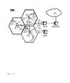
- Fig. 1 shows as an example of a communication network in which the invention can be implemented a communication network CN according to the standard 3GPP LTE.
- Said communication network CN comprises base stations BS1-BS3, user terminals UE1-UE4, a serving gateway SGW, a packet data network gateway PDNGW, and a mobility management entity MME.
- Each of said user terminals UE1-UE4 is connected via radio connections to one or multiple of said base stations BS1-BS3, which is symbolized by flashes in fig. 1 .
- the base stations BS1-BS3 are in turn connected to the serving gateway SGW and to the mobility management entity MME, i.e. to the evolved packet core (EPC), via the so-called S1 interface.
- EPC evolved packet core
- the base stations BS1-BS3 are connected among each other via the so-called X2 interface.
- the serving gateway SGW is connected to the packet data network gateway PDNGW, which is in turn connected to an external IP network IPN.
- the S1 interface is a standardized interface between a base station BS1-BS3, i.e. a eNodeB in this example, and the Evolved Packet Core (EPC).
- the S1 interface has two flavours, S1-MME for exchange of signalling messages between the base station BS1-BS3 and the mobility management entity MME and S1-U for the transport of user datagrams between the base station BS1-BS3 and the serving gateway SGW.
- the X2 interface is added in 3GPP LTE standard primarily in order to transfer the user plane signal and the control plane signal during handover.
- the serving gateway SGW performs routing of the IP user data between the base station BS1-BS3 and the packet data network gateway PDNGW. Furthermore, the serving gateway SGW serves as a mobile anchor point during handover either between different base stations, or between different 3GPP access networks.
- EPS Evolved Packet System
- the mobility management entity MME performs tasks of the subscriber management and the session management, and also performs the mobility management during handover between different access networks.
- Fig. 2 schematically shows the structure of a user terminal UE and a base station BS in which the invention can be implemented.
- the base station BS comprises by way of example three modem unit boards MU1-MU3 and a control unit board CU1, which in turn comprises a media dependent adapter MDA.
- the three modem unit boards MU1-MU3 are connected to the control unit board CU1, and the control unit board CU1 is in turn connected to a remote radio head RRH via a so-called Common Public Radio Interface (CPRI).
- CPRI Common Public Radio Interface
- the remote radio head RRH is connected by way of example to two remote radio head antennas RRHA1 and RRHA2 for transmission and reception of data via a radio interface.
- the media dependent adapter MDA is connected to the mobility management entity MME and to the serving gateway SGW and thus to the packet data network gateway PDNGW, which is in turn connected to the external IP network IPN.
- the user terminal UE comprises by way of example two user terminal antennas UEA1 and UEA2, a modem unit board MU4, a control unit board CU2, and interfaces INT.
- the two user terminal antennas UEA1 and UEA2 are connected to the modem unit board MU4.
- the modem unit board MU4 is connected to the control unit board CU2, which is in turn connected to interfaces INT.
- the modem unit boards MU1-MU4 and the control unit boards CU1, CU2 may comprise by way of example Field Programmable Gate Arrays (FPGA), Digital Signal Processors (DSP), micro processors, switches and memories, like e.g. Double Data Rate Synchronous Dynamic Random Access Memories (DDR-SDRAM) in order to be enabled to perform the tasks described above.
- FPGA Field Programmable Gate Arrays
- DSP Digital Signal Processors
- DDR-SDRAM Double Data Rate Synchronous Dynamic Random Access Memories
- the remote radio head RRH comprises the so-called radio equipment, e.g. modulators and amplifiers, like delta-sigma modulators (DSM) and switch mode amplifiers.
- modulators and amplifiers like delta-sigma modulators (DSM) and switch mode amplifiers.
- IP data received from the external IP network IPN are transmitted from the packet data network gateway PDNGW via the serving gateway SGW to the media dependent adapter MDA of the base station BS on an EPS bearer.
- the media dependent adapter MDA allows for a connectivity of different media like e.g. video streaming or web browsing.
- the control unit board CU1 performs tasks on layer 3, i.e. on the radio resource control (RRC) layer, such as measurements and cell reselection, handover and RRC security and integrity.
- RRC radio resource control
- control unit board CU1 performs tasks for Operation and Maintenance, and controls the S1 interfaces, the X2 interfaces, and the Common Public Radio Interface.
- the control unit board CU1 sends the IP data received from the serving gateway SGW to a modem unit board MU1-MU3 for further processing.
- PDCP Packet Data Convergence Protocol
- RLC Radio Link Control
- ARQ Automatic Repeat Request
- MAC Media Access Control
- the three modem unit boards MU1-MU3 perform data processing on the physical layer, i.e. coding, modulation, and antenna and resource-block mapping.
- the coded and modulated data are mapped to antennas and resource blocks and are sent as transmission symbols from the modem unit board MU1-MU3 via the control unit board CU over the Common Public Radio Interface to the remote radio head and the respective remote radio head antenna RRHA1, RRHA2 for transmission over an air interface.
- the Common Public Radio Interface allows the use of a distributed architecture where base stations BS, containing the so-called radio equipment control, are connected to remote radio heads RRH preferably via lossless fibre links that carry the CPRI data.
- This architecture reduces costs for service providers because only the remote radio heads RRH containing the so-called radio equipment, like e.g. amplifiers, need to be situated in environmentally challenging locations.
- the base stations BS can be centrally located in less challenging locations where footprint, climate, and availability of power are more easily managed.
- the user terminal antennas UEA1, UEA2 receive the transmission symbols, and provide the received data to the modem unit board MU4.
- the modem unit board MU4 performs data processing on the physical layer, i.e. antenna and resource-block demapping, demodulation and decoding.
- MAC Media Access Control
- RLC Radio Link Control
- ARQ Automatic Repeat Request
- PDCP Packet Data Convergence Protocol
- the processing on the modem unit board MU4 results in IP data which are sent to the control unit board CU2, which performs tasks on layer 3, i.e. on the radio resource control (RRC) layer, such as measurements and cell reselection, handover and RRC security and integrity.
- RRC radio resource control
- the IP data are transmitted from the control unit board CU2 to respective interfaces INT for output and interaction with a user.
- data transmission is performed in an analogue way in the reverse direction from the user terminal UE to the external IP network IPN.
- Fig. 3 schematically shows the signal to interference and noise ratio (SINR) and the block error rate (BLER) at a receiver without adjustment of the modulation and coding scheme (MCS) according to the prior art.
- SINR signal to interference and noise ratio
- BLER block error rate
- the so-called received signal strength indication (RSSI) at the receiver is plotted in arbitrary units against an arbitrary time scale.
- the so-called modulation and coding scheme (MCS) for transmission from the transmitter is plotted in arbitrary units against the arbitrary time scale.
- the so-called block error rate (BLER) at the receiver is plotted in arbitrary units against the arbitrary time scale.
- CSI channel state information
- SINR modulation and coding scheme
- the modulation and coding scheme is constant between the transmission of two consecutive channel state information (CSI).
- SINR signal to interference and noise ratio
- BLER block error rate
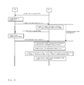
- Fig. 4 schematically shows exemplarily a procedure for adjusting of the modulation and coding scheme (MCS) according to an embodiment of the invention.
- a transmitter BS as e.g. a base station, sends a signalling message CRS1 to a receiver, as e.g. a user terminal UE.
- Said signalling message CRS1 comprises downlink reference signals, as e.g. cell-specific reference signals used for channel estimation.
- the receiver UE determines a channel state comprising e.g. quantized signal to interference and noise ratios (SINR) as a channel quality based on the downlink reference signals CRS1.
- SINR quantized signal to interference and noise ratios
- Said signalling message comprises channel state information CSI1, as e.g. a so-called channel quality indicator, a so-called precoding matrix indicator, or a so-called rank indicator.
- the channel quality indicator represents either a signal to interference and noise ratio (SINR), which may also be quantized, or a recommended modulation scheme and coding scheme that should, preferably, be used for the downlink transmission.
- SINR signal to interference and noise ratio
- the precoding matrix indicator provides a precoder matrix that should, preferably, be used for downlink transmission.
- the rank indicator provides information about the channel rank, i.e. the number of layers that should, preferably, be used for downlink transmission to a user terminal. As the channel state changes in the time lapse, the channel state information CSI1 gets outdated with increasing time.
- the transmitter BS determines an appropriate precoding vector based on the received channel state information CSI1. Then, the transmitter BS determines the resulting signal to interference and noise ratio (SINR) based on the selected precoding vector and based on the received channel state information CSI1. The transmitter BS now determines an appropriate modulation and coding scheme (MCS) based on the determined resulting signal to interference and noise ratio (SINR).
- MCS modulation and coding scheme
- SINR signal to interference and noise ratio
- the channel vector h can be measured by the user terminal by evaluating the transmitted common reference signals.
- the vector x of transmitted signals at each of the transmit antennas is created by multiplying the transmit symbols s with one codebook vector, i.e. precoding vector, out of a set of possible codebook entries.
- SINR MISO E tx h T ⁇ x 2
- E z 2 E tx h T ⁇ x 2
- a fifth step denoted with 5 in analogy to step 1, the transmitter BS sends a signalling message CRS2 comprising downlink reference signals to the receiver UE.
- the receiver UE determines a channel state comprising e.g. quantized signal to interference and noise ratios (SINR) as a channel quality based on the downlink reference signals CRS2.
- SINR quantized signal to interference and noise ratios
- a seventh step denoted with 7, in analogy to step 3, the receiver UE sends a signalling message at time t 17 to the transmitter BS.
- Said signalling message comprises channel state information CSI2, as e.g. a so-called channel quality indicator, a so-called precoding matrix indicator, or a so-called rank indicator.
- the channel quality indicator represents either a signal to interference and noise ratio (SINR), which may also be quantized, or a recommended modulation scheme and coding scheme that should, preferably, be used for the downlink transmission.
- SINR signal to interference and noise ratio
- the precoding matrix indicator provides a precoder matrix that should, preferably, be used for downlink transmission.
- the rank indicator provides information about the channel rank, i.e. the number of layers that should, preferably, be used for downlink transmission to a user terminal.
- SINR signal to interference and noise ratio
- the transmitter BS determines a time-dependent variation of the signal to interference and noise ratio (SINR) based on the difference between the signal to interference and noise ratio (SINR) determined in step 4 and determined in step 8.
- SINR signal to interference and noise ratio
- the transmitter BS determines a recent precoding vector based on the received recent channel state information CSI2. Then, the transmitter BS determines a resulting signal to interference and noise ratio (SINR) based on the recent precoding vector and based on the received recent channel state information CSI2.
- SINR signal to interference and noise ratio
- the transmitter BS now can determine an appropriate modulation and coding scheme (MCS) at an arbitrary point in time based on the resulting recent signal to interference and noise ratio (SINR) determined in step 10, and based on the time-dependent variation of the signal to interference and noise ratio (SINR) determined in step 9.
- MCS modulation and coding scheme
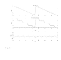
- Fig. 5 schematically shows the signal to interference and noise ratio (SINR) and the block error rate (BLER) at a receiver with adjustment of the modulation and coding scheme (MCS) according to an embodiment of the invention.
- SINR signal to interference and noise ratio
- BLER block error rate
- the so-called received signal strength indication (RSSI) at the receiver is plotted in arbitrary units against an arbitrary time scale.
- the so-called modulation and coding scheme (MCS) for transmission from the transmitter is plotted in arbitrary units against the arbitrary time scale.
- the so-called block error rate (BLER) at the receiver is plotted in arbitrary units against the arbitrary time scale.
- CSI channel state information
- SINR_start a resulting signal to interference and noise ratio
- SINR_start modulation and coding scheme
- SINR modulation and coding scheme
- SINR signal to interference and noise ratio
- the transmitter BS can now for each time 2-17 estimate the degradation of the signal to interference and noise ratio (SINR) and react on the degradation by reducing the modulation and coding scheme MCS, i.e. by using an easier, more robust modulation and coding scheme, in order to correct for the lower signal to interference and noise ratio (SINR).
- SINR signal to interference and noise ratio
Landscapes
- Engineering & Computer Science (AREA)
- Quality & Reliability (AREA)
- Computer Networks & Wireless Communication (AREA)
- Signal Processing (AREA)
- Mobile Radio Communication Systems (AREA)
Priority Applications (1)
| Application Number | Priority Date | Filing Date | Title |
|---|---|---|---|
| EP10305471A EP2385643A1 (de) | 2010-05-03 | 2010-05-03 | Verfahren zur Auswahl eines Modulations- und Codierschemas sowie Vorrichtung dafür |
Applications Claiming Priority (1)
| Application Number | Priority Date | Filing Date | Title |
|---|---|---|---|
| EP10305471A EP2385643A1 (de) | 2010-05-03 | 2010-05-03 | Verfahren zur Auswahl eines Modulations- und Codierschemas sowie Vorrichtung dafür |
Publications (1)
| Publication Number | Publication Date |
|---|---|
| EP2385643A1 true EP2385643A1 (de) | 2011-11-09 |
Family
ID=42735740
Family Applications (1)
| Application Number | Title | Priority Date | Filing Date |
|---|---|---|---|
| EP10305471A Withdrawn EP2385643A1 (de) | 2010-05-03 | 2010-05-03 | Verfahren zur Auswahl eines Modulations- und Codierschemas sowie Vorrichtung dafür |
Country Status (1)
| Country | Link |
|---|---|
| EP (1) | EP2385643A1 (de) |
Cited By (8)
| Publication number | Priority date | Publication date | Assignee | Title |
|---|---|---|---|---|
| CN103227689A (zh) * | 2012-01-30 | 2013-07-31 | 中兴通讯股份有限公司 | 功率参数的处理方法及装置 |
| WO2013139036A1 (en) * | 2012-03-23 | 2013-09-26 | Nec(China) Co., Ltd. | Method and apparatus for scheduling user equipment |
| KR20140002299A (ko) * | 2012-06-29 | 2014-01-08 | 삼성전자주식회사 | 신호 간섭 여부에 따라 디투디 통신 모드를 선택하는 장치 및 방법 |
| WO2014089949A1 (zh) * | 2012-12-14 | 2014-06-19 | 华为技术有限公司 | 信道质量指示反馈方法、装置和用户设备 |
| EP3065328A1 (de) * | 2015-03-04 | 2016-09-07 | Ntt Docomo, Inc. | Verfahren, benutzergerät und basisstation zur anpassung von modulations- und codierungsschemen |
| GB2544518A (en) * | 2015-11-19 | 2017-05-24 | Samsung Electronics Co Ltd | Channel quality indicators |
| WO2017152930A1 (en) * | 2016-03-07 | 2017-09-14 | Telefonaktiebolaget Lm Ericsson (Publ) | Radio link adaptation in radio communication systems |
| CN113507606A (zh) * | 2021-07-07 | 2021-10-15 | 深圳市朗强科技有限公司 | 超高清视频压缩算法的选择方法、选择装置及选择设备 |
Citations (8)
| Publication number | Priority date | Publication date | Assignee | Title |
|---|---|---|---|---|
| US6760882B1 (en) * | 2000-09-19 | 2004-07-06 | Intel Corporation | Mode selection for data transmission in wireless communication channels based on statistical parameters |
| US20040142698A1 (en) * | 2002-11-01 | 2004-07-22 | Interdigital Technology Corporation | Method for channel quality prediction for wireless communication systems |
| US20050249159A1 (en) * | 2004-05-07 | 2005-11-10 | Santosh Abraham | Transmission mode and rate selection for a wireless communication system |
| US20060268976A1 (en) * | 2005-05-03 | 2006-11-30 | Motorola, Inc. | Method and apparatus for determining channel quality and performing adaptive modulation coding within a multi carrier communication system |
| US20070280116A1 (en) * | 2006-06-05 | 2007-12-06 | Hong Kong University Of Science And Technology | Adaptive multi-user mimo non-cooperative threshold-based wireless communication system using limited channel feedback |
| US20090116544A1 (en) * | 2007-11-01 | 2009-05-07 | Renesas Technology Corporation | Performance-based link adaptation techniques using throughput indicator |
| US20090221238A1 (en) * | 2005-12-13 | 2009-09-03 | Electronics And Telecommunications Research Instit | Transmitting apparatus and transmitting method of base station, and receiving apparatus and communication method of ue in mobile communication system |
| US20090316636A1 (en) * | 2008-06-18 | 2009-12-24 | Beceem Communications Inc. | Selecting a transmission mode between a subscriber and a base station |
-
2010
- 2010-05-03 EP EP10305471A patent/EP2385643A1/de not_active Withdrawn
Patent Citations (8)
| Publication number | Priority date | Publication date | Assignee | Title |
|---|---|---|---|---|
| US6760882B1 (en) * | 2000-09-19 | 2004-07-06 | Intel Corporation | Mode selection for data transmission in wireless communication channels based on statistical parameters |
| US20040142698A1 (en) * | 2002-11-01 | 2004-07-22 | Interdigital Technology Corporation | Method for channel quality prediction for wireless communication systems |
| US20050249159A1 (en) * | 2004-05-07 | 2005-11-10 | Santosh Abraham | Transmission mode and rate selection for a wireless communication system |
| US20060268976A1 (en) * | 2005-05-03 | 2006-11-30 | Motorola, Inc. | Method and apparatus for determining channel quality and performing adaptive modulation coding within a multi carrier communication system |
| US20090221238A1 (en) * | 2005-12-13 | 2009-09-03 | Electronics And Telecommunications Research Instit | Transmitting apparatus and transmitting method of base station, and receiving apparatus and communication method of ue in mobile communication system |
| US20070280116A1 (en) * | 2006-06-05 | 2007-12-06 | Hong Kong University Of Science And Technology | Adaptive multi-user mimo non-cooperative threshold-based wireless communication system using limited channel feedback |
| US20090116544A1 (en) * | 2007-11-01 | 2009-05-07 | Renesas Technology Corporation | Performance-based link adaptation techniques using throughput indicator |
| US20090316636A1 (en) * | 2008-06-18 | 2009-12-24 | Beceem Communications Inc. | Selecting a transmission mode between a subscriber and a base station |
Non-Patent Citations (1)
| Title |
|---|
| MULLER A ET AL: "Improving HSDPA link adaptation by considering the age of channel quality feedback information", VEHICULAR TECHNOLOGY CONFERENCE, 2005. VTC-2005-FALL. 2005 IEEE 62ND DALLAS, TX, USA 25-28 SEPT., 2005, PISCATAWAY, NJ, USA,IEEE LNKD- DOI:10.1109/VETECF.2005.1558220, vol. 3, 25 September 2005 (2005-09-25), pages 1643 - 1647, XP010878723, ISBN: 978-0-7803-9152-9 * |
Cited By (22)
| Publication number | Priority date | Publication date | Assignee | Title |
|---|---|---|---|---|
| CN103227689A (zh) * | 2012-01-30 | 2013-07-31 | 中兴通讯股份有限公司 | 功率参数的处理方法及装置 |
| CN103227689B (zh) * | 2012-01-30 | 2018-07-24 | 中兴通讯股份有限公司 | 功率参数的处理方法及装置 |
| US9532371B2 (en) | 2012-03-23 | 2016-12-27 | Nec (China) Co., Ltd. | Method and apparatus for scheduling user equipment |
| WO2013139036A1 (en) * | 2012-03-23 | 2013-09-26 | Nec(China) Co., Ltd. | Method and apparatus for scheduling user equipment |
| CN103814616A (zh) * | 2012-03-23 | 2014-05-21 | 日电(中国)有限公司 | 用于调度用户设备的方法和设备 |
| CN103814616B (zh) * | 2012-03-23 | 2017-07-18 | 日电(中国)有限公司 | 用于调度用户设备的方法和设备 |
| KR20140002299A (ko) * | 2012-06-29 | 2014-01-08 | 삼성전자주식회사 | 신호 간섭 여부에 따라 디투디 통신 모드를 선택하는 장치 및 방법 |
| US20140018121A1 (en) * | 2012-06-29 | 2014-01-16 | Sungkyunkwan University Foundation Corporate Callaboration | Apparatus and method for selecting d2d communication mode depending on signal interference |
| US10064223B2 (en) * | 2012-06-29 | 2018-08-28 | Samsung Electronics Co., Ltd. | Apparatus and method for selecting D2D communication mode depending on signal interference |
| WO2014089949A1 (zh) * | 2012-12-14 | 2014-06-19 | 华为技术有限公司 | 信道质量指示反馈方法、装置和用户设备 |
| US9712277B2 (en) | 2012-12-14 | 2017-07-18 | Huawei Technologies Co., Ltd. | Channel quality indicator feedback method and apparatus, and user equipment |
| CN104041127A (zh) * | 2012-12-14 | 2014-09-10 | 华为技术有限公司 | 信道质量指示反馈方法、装置和用户设备 |
| US20160262167A1 (en) * | 2015-03-04 | 2016-09-08 | NTI DoCoMo, Inc. | Method, User Equipment and Base Station For Adjusting Modulation and Coding Scheme |
| EP3065328A1 (de) * | 2015-03-04 | 2016-09-07 | Ntt Docomo, Inc. | Verfahren, benutzergerät und basisstation zur anpassung von modulations- und codierungsschemen |
| US10405323B2 (en) * | 2015-03-04 | 2019-09-03 | Ntt Docomo, Inc. | Method, user equipment and base station for adjusting modulation and coding scheme |
| GB2544518A (en) * | 2015-11-19 | 2017-05-24 | Samsung Electronics Co Ltd | Channel quality indicators |
| US10367626B2 (en) | 2015-11-19 | 2019-07-30 | Samsung Electronics Co., Ltd. | Channel quality indicators |
| GB2544518B (en) * | 2015-11-19 | 2020-02-12 | Samsung Electronics Co Ltd | Channel quality indicators |
| WO2017152930A1 (en) * | 2016-03-07 | 2017-09-14 | Telefonaktiebolaget Lm Ericsson (Publ) | Radio link adaptation in radio communication systems |
| US10958372B2 (en) | 2016-03-07 | 2021-03-23 | Telefonaktiebolaget Lm Ericsson (Publ) | Radio link adaptation in communication systems |
| CN113507606A (zh) * | 2021-07-07 | 2021-10-15 | 深圳市朗强科技有限公司 | 超高清视频压缩算法的选择方法、选择装置及选择设备 |
| CN113507606B (zh) * | 2021-07-07 | 2024-05-28 | 深圳市朗强科技有限公司 | 超高清视频压缩算法的选择方法、选择装置及选择设备 |
Similar Documents
| Publication | Publication Date | Title |
|---|---|---|
| JP6545232B2 (ja) | 無線通信システムにおいて上り(ul)参照信号(rs)の送信電力を導出するための方法及び装置 | |
| US9287957B2 (en) | Method for multi-antenna uplink transmission | |
| US9960884B2 (en) | System and method for channel state information feedback in wireless communications systems | |
| US9496939B2 (en) | Adaptive transmission mode switching | |
| EP4000195B1 (de) | Cqi-sättigungsabschwächung in massiven mu-mimo-systemen | |
| EP2385643A1 (de) | Verfahren zur Auswahl eines Modulations- und Codierschemas sowie Vorrichtung dafür | |
| US9832780B2 (en) | Method for estimating uplink control channel quality | |
| US9667457B2 (en) | Radio communication device and signal processing method | |
| US12167347B2 (en) | Link-adaptation power backoff | |
| CN115734270B (zh) | 无线通信方法、用户设备和基站 | |
| KR20140127342A (ko) | 기지국과 사용자 장비 사이의 송신을 위한 변조 및 코딩 방식 제어 | |
| WO2013169184A2 (en) | Scheduling a user equipment in a communication system | |
| JP6352280B2 (ja) | ネットワーク装置及びユーザ端末 | |
| US11223401B2 (en) | Technique for selecting a MIMO transport format | |
| US12519561B2 (en) | Network node and method for link adaption in a wireless communication network | |
| US20110305154A1 (en) | Transmitting a First and a Second Channel Quality Information Between Two Network Elements | |
| WO2016120454A1 (en) | Methods and devices for reporting filtering information of channel status information | |
| US20250055540A1 (en) | Method and apparatus for achieving model compatibility in two-sided model and its parameter signaling | |
| US20250088229A1 (en) | Method and device used for wireless communication | |
| WO2025096708A1 (en) | An iterative procedure for separate receive/transmit training enhancement for precoder channel state information feedback | |
| WO2025096731A1 (en) | An iterative procedure for separate receive/transmit training enhancement for channel measurement channel state information feedback | |
| CN120456085A (zh) | 一种被用于无线通信的节点中的csi测量的方法和装置 | |
| WO2017026407A1 (ja) | 基地局及び無線端末 | |
| CN118632289A (zh) | 一种被用于无线通信的节点中的方法和装置 | |
| CN120434682A (zh) | 一种被用于无线通信的节点中的csi测量的方法和装置 |
Legal Events
| Date | Code | Title | Description |
|---|---|---|---|
| AK | Designated contracting states |
Kind code of ref document: A1 Designated state(s): AL AT BE BG CH CY CZ DE DK EE ES FI FR GB GR HR HU IE IS IT LI LT LU LV MC MK MT NL NO PL PT RO SE SI SK SM TR |
|
| AX | Request for extension of the european patent |
Extension state: BA ME RS |
|
| PUAI | Public reference made under article 153(3) epc to a published international application that has entered the european phase |
Free format text: ORIGINAL CODE: 0009012 |
|
| RAP1 | Party data changed (applicant data changed or rights of an application transferred) |
Owner name: ALCATEL LUCENT |
|
| 17P | Request for examination filed |
Effective date: 20120315 |
|
| 17Q | First examination report despatched |
Effective date: 20120912 |
|
| 111Z | Information provided on other rights and legal means of execution |
Free format text: AL AT BE BG CH CY CZ DE DK EE ES FI FR GB GR HR HU IE IS IT LI LT LU LV MC MK MT NL NO PL PT RO SE SI SK SM TR Effective date: 20130410 |
|
| STAA | Information on the status of an ep patent application or granted ep patent |
Free format text: STATUS: THE APPLICATION IS DEEMED TO BE WITHDRAWN |
|
| 18D | Application deemed to be withdrawn |
Effective date: 20130712 |