EP2385356B1 - Wäge- und Sortiervorrichtung - Google Patents
Wäge- und Sortiervorrichtung Download PDFInfo
- Publication number
- EP2385356B1 EP2385356B1 EP11003709.0A EP11003709A EP2385356B1 EP 2385356 B1 EP2385356 B1 EP 2385356B1 EP 11003709 A EP11003709 A EP 11003709A EP 2385356 B1 EP2385356 B1 EP 2385356B1
- Authority
- EP
- European Patent Office
- Prior art keywords
- weighing
- platform
- sorting
- end section
- accordance
- Prior art date
- Legal status (The legal status is an assumption and is not a legal conclusion. Google has not performed a legal analysis and makes no representation as to the accuracy of the status listed.)
- Active
Links
Images
Classifications
-
- G—PHYSICS
- G01—MEASURING; TESTING
- G01G—WEIGHING
- G01G11/00—Apparatus for weighing a continuous stream of material during flow; Conveyor belt weighers
- G01G11/003—Details; specially adapted accessories
Definitions
- the present invention relates to a weighing and sorting device for general cargo.
- Checkweighers where a weighing belt is supported on a load cell, are used within weight control production processes.
- the data obtained can be evaluated immediately within the framework of an inline process control, for example, to sort general cargo, in particular to sort out faulty weights.
- a feed belt is arranged to supply the goods to the weighing belt.
- a discharge belt with a lateral pusher or a tilting belt is arranged in order to carry out a sorting or sorting out of the piece goods on the basis of the measurement results of the weighing cell.
- the weighing result is negatively influenced by the band transitions.
- the band transitions When transferring the piece goods from the feed belt to the weighing belt occur due to the unsteady transition between the two belts vibrations, through which the weighing belt in vibration which reduces the accuracy of the determination of the weight of the piece goods by the load cell. The same applies to the transfer of the piece goods from the weighing belt to the discharge belt for the weight determination of the subsequent piece goods.
- document US 5,877,456 describes a calibration of a belt scale using test chains.
- the belt weigher is divided into a feed section, a weighing section and a discharge section, to which a common weighing belt is assigned.
- document GB 868,962 discloses a belt weigher with a centrally located weighing section.
- document GB 1 545 105 discloses a belt weighing device having a feed area, a weighing area and a discharge area.
- document US 2007/0181349 A1 discloses a device with a feed belt, a weighing belt and a discharge belt with pusher as described above.
- document WO 02/054025 A1 discloses a piece goods weighing and sorting apparatus comprising a feed platform, a weighing platform and a sorting platform.
- the invention has for its object to provide a weighing and sorting device of the type mentioned, which allows a determination of weight with high accuracy.
- three platforms are provided according to the invention, which have a single common conveyor belt on which the cargo can be transported across all platforms, and by a single motor, such as a drum motor, which does not weighed, can be driven.
- the band construction according to the invention is less expensive than the band construction known from the prior art.
- the device is designed to carry out the sorting, in particular sorting out, automatically and / or as a function of a signal of a weighing cell.
- the sorting platform between an extended position and a retracted position is particularly horizontally adjustable and adjustable in length.
- the conveyor belt of the device according to the invention in the extended position directly adjacent to another conveyor belt and through this further conveyor belt, the cargo can be supplied to a further processing or processing. There is then no sorting out of the piece goods.
- the sorting platform is retracted or withdrawn in the case of a wrong-weight piece of goods, a gap arises between the conveyor belt of the device according to the invention and the further conveyor belt, and the piece goods can fall down and thereby be sorted out.
- the device is adapted to adjust the conveyor belt course to the changed position when adjusting the position of the sorting platform.
- the sorting platform is formed in this case as a withdrawal belt and the sorting or sorting out not a pusher, which pushes a Topicsortierendes piece goods perpendicular to the conveying direction of the discharge belt and thereby in turn triggers vibrations, or a Kippband that - unlike a Retraction band - not only has horizontal motion components and thus influence on a vertical weight determination, is anticipated, the accuracy of weight determination can be further increased.
- the sorting platform comprises an end section facing the weighing platform and / or an end section facing away from the weighing platform, wherein the facing or inlet-side end section and / or the feed platform are fixedly held on the device and / or the opposite or outlet-side end section movably guided on the device.
- the sorting platform between the extended position and the retracted position, as described above be adjusted or length.
- the movable guide of the remote or outlet side end portion is formed as a roller guide.
- a roller guide has compared to a sliding guide a reduced friction, whereby repercussions of the adjustment of the sorting platform can be further reduced to the weighing platform.
- the roller guide may comprise a pulley assembly fixedly connected to the distal end portion and extending along at least one rail, e.g. one or more round rods, which are in particular fixedly mounted on the device, in particular a frame or frame of the device, is movable.
- a pulley assembly fixedly connected to the distal end portion and extending along at least one rail, e.g. one or more round rods, which are in particular fixedly mounted on the device, in particular a frame or frame of the device, is movable.
- the facing or inlet-side end portion and the remote or outlet-side end portion are adapted to intermesh with each other, preferably in all adjustment positions of remote end portion.
- the conveyor belt can be supported over the entire length of the sorting platform and thus supported.
- a soft start and / or soft spout may be provided for the extended position and / or the retracted position.
- the adjustment of the sorting platform can be effected by an actuator, for example a lifting cylinder.
- the soft spout may e.g. be realized by a cushioning of the actuator, such as a spring, which allows a smooth start or stop the remote or outlet side end portion.
- a corresponding control of the actuator may be provided to allow a smooth start or braking.
- the conveyor belt is guided in and out on non-rotating deflection means, i.
- non-rotating deflection means i.
- deflection devices which preferably have a deflection edge or Umlenkrundung for the conveyor belt, can be cleaned easier and better than rotatable pulleys. This is particularly advantageous when using the weighing and sorting device in the food industry.
- the two non-rotating deflection devices are the feed platform and the aforementioned remote or outlet end section of the sorting platform.
- At least one pin or sprocket wheel can be provided, wherein the conveyor belt for this purpose, in particular on or On both sides of the edge, provided with transport holes, ie the pin or sprocket wheel is connected to the drive and in turn drives on the conveyor holes on the conveyor belt.
- the conveyor belt for this purpose, in particular on or On both sides of the edge, provided with transport holes, ie the pin or sprocket wheel is connected to the drive and in turn drives on the conveyor holes on the conveyor belt.
- a weighing platform associated weighing cell can be fixedly mounted on the device, in particular a frame or frame of the device.
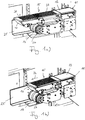
- the in the Fig. 1-3 illustrated combined weighing and sorting device comprises a feed platform 11, a weighing platform 13 and a sorting platform 15 designed as Abfuellane.
- the platforms 11, 13, 15 immediately adjoin each other and do not overlap.
- an angled, continuous support plane is defined, over which a common for the platforms 11, 13, 15, closed belt conveyor belt 17 or endless conveyor belt is guided.
- the belt conveyor belt 17 is driven by a drive, in particular a drum motor 19.
- the drive 19 or the drive shaft of the drive 19 is arranged below the platforms 11, 13, 15 and within the loop formed by the conveyor belt 17.
- the weighing platform 13 is coupled to the weighing cell 21 arranged underneath the weighing platform 13, which is designed to determine the weight of the piece goods moving dynamically across the weighing platform 13.
- the load cell 21 is supported by a cross member 23 on a rear wall 25 of the device or firmly held.
- the rear wall 25 in turn is supported on a frame or frame of the device.
- the drum motor 19 comprises two pin or sprockets 27, which engage in transport holes, not shown, which are formed on the two edge sides of the endless conveyor belt 17. Due to the positive connection of the drive 19 with the endless conveyor belt 17, a slip between these two components can be excluded.
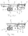
- the sorting platform 15 is formed in two parts, i. the sorting platform 15 comprises an inlet side, the weighing platform 13 facing end portion 29 and an outlet side, the weighing platform 13 facing away from the end portion 31.
- the two end portions 29, 31 each have a comb-like structure, the tines of the two end portions 29, 31 are complementary to each other, so that the two end sections 29, 31 can intermesh with one another.
- the two end portions 29, 31 of the sorting platform 15 are movable relative to each other.
- the sorting platform 15 is telescopically extendable.
- the inlet-side end portion 29 is fixedly and immovably supported on the overall device.
- the outlet-side end portion 31, however, is mounted continuously displaceable or adjustable in the conveying direction 33.
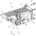
- the roller guide comprises two fixedly mounted on the device rails in the form of round rods 35, of which in Fig. 3 only one round rod 35 can be seen, and for each of the two round rods 35 a roller carriage 37 with four rollers 39, which are arranged in pairs above and below the respective round rod 35 and are in rolling contact with this.
- the sorting platform 15 is thus adjustable in length.
- the Fig. 1a and 2a can connect to the weighing and sorter device shown on the outlet side another conveyor belt, with which the transported over the device cargo can be transferred to another processing station.
- the retracted position of the outlet side end portion 31 in accordance with Fig. 1b and 2 B due to its weight, the general cargo falls downwards and can thus be sorted or sorted out.
- a corresponding adjustment of the course of the endless conveyor belt 17 is preferred.
- This adaptation is achieved by a deflection roller 41 connected to the outlet-side end section 31, which is arranged in the belt direction between the outlet-side end of the outlet-side end section 31 and the drive 19. Due to the predetermined arrangement of the outlet-side end of the opposite end portion 31, the guide roller 41 and the drum motor 19, a change in length of the upper run is compensated by a corresponding change in length of the loop formed by the guide roller 41 in the lower run.
- the two deflection points for the upper strand of the conveyor belt 17 are formed by the inlet end of the feed platform 11 and the outlet end of the opposite end portion 31. These two ends are each not formed by a rotatable pulley, but formed non-rotating. Because in these areas no rotatable Parts are provided, the weighing and sorting device can be cleaned easily and quickly.
- the weighing and sorting device allows a vibration-free and therefore highly accurate determination of the weight of piece goods.
Landscapes
- Physics & Mathematics (AREA)
- General Physics & Mathematics (AREA)
- Sorting Of Articles (AREA)
Description
- Die vorliegende Erfindung betrifft eine Wäge- und Sortiervorrichtung für Stückgut.
- Kontrollwaagen, bei denen ein Wägeband auf einer Wägezelle abgestützt bzw. aufgebaut ist, werden innerhalb von Produktionsprozessen zur Gewichtskontrolle eingesetzt. Die dabei gewonnenen Daten können im Rahmen einer Inline-Prozesskontrolle sofort ausgewertet werden, beispielsweise um Stückgut zu sortieren, insbesondere Fehlgewichte auszusortieren.
- Um einen möglichst hohen Durchsatz zu erreichen, werden hierbei vor allem dynamische Kontrollwaagen eingesetzt, bei denen das zu wiegende Stückgut im Durchlauf gewogen wird, d.h. die Messungen werden vorgenommen, während sich das Stückgut aufgrund einer kontinuierlichen Bewegung des Wägebands ohne Stopp über eine zugeordnete Wägezelle hinweg bewegt. Vor dem Wägeband ist ein Zuführband angeordnet, um dem Wägeband das Stückgut zuzuführen. Nach dem Wägeband ist beispielsweise ein Abführband mit seitlichem Pusher oder ein Kippband angeordnet, um ein Sortieren bzw. Aussortieren des Stückguts anhand der Messergebnisse der Wägezelle durchzuführen.
- Allerdings wird das Wägeergebnis durch die Bandübergänge negativ beeinflusst. Bei der Übergabe des Stückguts von dem Zuführband zu dem Wägeband treten aufgrund des unstetigen Übergangs zwischen den beiden Bändern Erschütterungen auf, durch die das Wägeband in Schwingungen versetzt wird, die die Genauigkeit der Bestimmung des Gewichts des Stückguts durch die Wägezelle herabsetzen. Analoges gilt bei der Übergabe des Stückguts von dem Wägeband zu dem Abführband für die Gewichtsbestimmung des nachfolgenden Stückguts.
- Dokument
US 5,877,456 beschreibt eine Kalibrierung einer Bandwaage mit Hilfe von Testketten. Die Bandwaage ist in einen Zuführabschnitt, einen Wägeabschnitt und einen Abführabschnitt unterteilt, denen ein gemeinsames Wägeband zugeordnet ist. DokumentGB 868,962 GB 1 545 105 US 2007/0181349 A1 offenbart eine Vorrichtung mit einem Zuführband, einem Wägeband und einem Abführband mit Pusher, wie sie vorstehend beschrieben ist. DokumentWO 02/054025 A1 - Der Erfindung liegt die Aufgabe zugrunde, eine Wäge- und Sortiervorrichtung der eingangs genannten Art anzugeben, die eine Gewichtsbestimmung mit hoher Genauigkeit ermöglicht.
- Diese Aufgabe wird durch die Merkmale des Anspruchs 1 gelöst.
- Im Gegensatz zu einer aus dem Stand der Technik bekannten Bandkonstruktion mit einem Zuführband, einem Wägeband und einem als Sortiereinrichtung ausgebildeten Abführband, d.h. drei separaten Bändern, die jeweils eigene Umlenkrollen, Gurte und Antriebe besitzen, sind gemäß der Erfindung drei Plattformen vorgesehen, die ein einziges gemeinsames Förderband aufweisen, auf dem das Stückgut über sämtliche Plattformen hinweg transportiert werden kann, und das durch einen einzigen Motor, beispielsweise einen Trommelmotor, der nicht mit gewogen wird, angetrieben werden kann.
- Bandübergänge, die bei der Übergabe eines Stückguts Erschütterungen bzw. Schwingungen hervorrufen, sind daher nicht vorhanden, so dass die Bestimmung des Gewichts des Stückguts mit hoher Genauigkeit durchgeführt werden kann. Darüber hinaus ist die erfindungsgemäße Bandkonstruktion kostengünstiger als die aus dem Stand der Technik bekannte Bandkonstruktion.
- Insbesondere ist die Vorrichtung dazu ausgebildet, das Sortieren, insbesondere Aussortieren, automatisch und/oder in Abhängigkeit von einem Signal einer Wägezelle durchzuführen.
- Zum Sortieren des Stückguts ist die Sortierplattform zwischen einer ausgefahrenen Stellung und einer eingefahrenen Stellung insbesondere horizontal verstellbar und längenverstellbar. Beispielsweise kann das Förderband der erfindungsgemäßen Vorrichtung in der ausgefahrenen Stellung unmittelbar an ein weiteres Förderband angrenzen und durch dieses weitere Förderband kann das Stückgut einer weiteren Be- oder Verarbeitung zugeführt werden. Es findet dann kein Aussortieren des Stückguts statt. Ist die Sortierplattform im Falle eines fehlgewichtigen Stückguts hingegen eingefahren bzw. zurückgezogen, entsteht eine Lücke zwischen dem Förderband der erfindungsgemäßen Vorrichtung und dem weiteren Förderband, und das Stückgut kann herunterfallen und dadurch aussortiert werden. Insbesondere ist die Vorrichtung dazu ausgebildet, bei Verstellung der Stellung der Sortierplattform den Förderbandverlauf an die geänderte Stellung anzupassen.
- Da die Sortierplattform in diesem Fall als Rückzugsband ausgebildet ist und das Sortieren bzw. Aussortieren nicht über einen Pusher, der ein auszusortierendes Stückgut senkrecht zur Förderrichtung von dem Abführband stößt und dadurch wiederum Erschütterungen bzw. Schwingungen auslöst, oder ein Kippband, das - anders als ein Rückzugsband - nicht nur horizontale Bewegungskomponenten besitzt und damit auf eine vertikale Gewichtsbestimmung Einfluss nimmt, vorweggenommen wird, kann die Genauigkeit der Gewichtsbestimmung weiter erhöht werden.
- Insbesondere umfasst die Sortierplattform einen der Wägeplattform zugewandten und/oder einlaufseitigen Endabschnitt und einen der Wägeplattform abgewandten und/oder auslaufseitigen Endabschnitt, wobei der zugewandte bzw. einlaufseitige Endabschnitt und/oder die Zufuhrplattform fest an der Vorrichtung gehaltert und/oder der abgewandte bzw. auslaufseitige Endabschnitt bewegbar an der Vorrichtung geführt ist. Durch den beweglichen, abgewandten bzw. auslaufseitigen Endabschnitt kann die Sortierplattform zwischen der ausgefahrenen Stellung und der eingefahrenen Stellung, wie sie vorstehend beschrieben sind, verstellt bzw. längenverstellt werden. Durch den fest gehalterten, zugewandten bzw. einlaufseitigen Endabschnitt kann eine gute mechanische Entkopplung der Wägeplattform von der Sortierplattform erreicht werden, so dass durch die Verstellbewegung der Sortierplattform bedingte Rückwirkungen auf die Wägeplattform zumindest weitgehend vermieden werden können.
- Bevorzugt ist die bewegbare Führung des abgewandten bzw. auslaufseitigen Endabschnitts als Laufrollenführung ausgebildet. Eine Laufrollenführung besitzt gegenüber einer Gleitführung eine verringerte Reibung, wodurch Rückwirkungen der Verstellbewegung der Sortierplattform auf die Wägeplattform noch weiter reduziert werden können.
- Beispielsweise kann die Laufrollenführung eine mit dem abgewandten bzw. auslaufseitigen Endabschnitt fest verbundene Laufrollenanordnung umfassen, die entlang wenigstens einer Schiene, z.B. einem oder mehreren Rundstäben, die insbesondere fest an der Vorrichtung, insbesondere einem Rahmen oder Gestell der Vorrichtung gehaltert sind, bewegbar ist.
- Bevorzugt sind der zugewandte bzw. einlaufseitige Endabschnitt und der abgewandte bzw. auslaufseitige Endabschnitt dazu ausgebildet, kämmend ineinander zu greifen, vorzugsweise in sämtlichen Verstellpositionen des abgewandten Endabschnitts. Hierdurch kann ein direkter Kontakt und damit eine erschütterungsverursachende Reibung zwischen den beiden Endabschnitten vermieden werden. Außerdem kann in diesem Fall das Förderband über die gesamte Länge der Sortierplattform hinweg unterbaut und damit abgestützt sein.
- Für die ausgefahrene Stellung und/oder die eingefahrene Stellung kann ein Sanftanlauf und/oder Sanftauslauf vorgesehen sein. Die Verstellung der Sortierplattform kann durch einen Aktuator, beispielsweise einen Hubzylinder, bewirkt werden. Der Sanftauslauf kann z.B. durch eine Endlagendämpfung des Aktuators, beispielsweise eine Feder, realisiert werden, die ein sanftes Anfahren bzw. Stoppen des abgewandten bzw. auslaufseitigen Endabschnitts ermöglicht. Alternativ oder zusätzlich kann eine entsprechende Ansteuerung des Aktuators vorgesehen sein, um ein sanftes Anfahren bzw. Bremsen zu ermöglichen.
- Nach einer Ausbildung der Erfindung ist das Förderband ein- und auslaufseitig über nicht-rotierende Umlenkeinrichtungen geführt, d.h. an den Längsenden der Vorrichtung werden - anders als im Stand der Technik - keine drehbaren Umlenkrollen verwendet. Derartige Umlenkeinrichtungen, die bevorzugt eine Umlenkkante oder Umlenkrundung für das Förderband aufweisen, können einfacher und besser gereinigt werden als drehbare Umlenkrollen. Dies ist insbesondere bei Verwendung der Wäge- und Sortiervorrichtung im Lebensmittelbereich von Vorteil. Insbesondere handelt es sich bei den beiden nicht-rotierenden Umlenkeinrichtungen um die Zuführplattform und den vorgenannten abgewandten bzw. auslaufseitigen Endabschnitt der Sortierplattform.
- Zum Antrieb des Förderbands kann wenigstens ein Stift- oder Stachelrad vorgesehen sein, wobei das Förderband hierfür, insbesondere ein- oder beidseitig randseitig, mit Transportlöchern versehen ist, d.h. das Stift- oder Stachelrad ist mit dem Antrieb verbunden und treibt seinerseits über die Transportlöcher das Förderband an. Hierdurch kann Schlupf zwischen dem Förderband und dem Antrieb, durch welchen Schlupf ggf. Vibrationen erzeugt werden, sicher verhindert werden.
- Eine Wägeplattform zugeordnete Wägezelle kann fest an der Vorrichtung, insbesondere einem Rahmen oder Gestell der Vorrichtung gehaltert sein.
- Weitere vorteilhafte Ausgestaltungen der Erfindung sind in den Unteransprüchen, der Figurenbeschreibung und der Zeichnung beschrieben.
- Die Erfindung wird im Folgenden beispielhaft unter Bezugnahme auf die Zeichnung beschrieben.
- Es zeigen, jeweils in schematischer Darstellung,
- Fig. 1
- eine perspektivische Ansicht einer Ausführungsform der erfindungsgemäßen Wäge- und Sortiervorrichtung mit einer Sortierplattform in einer ausgefahrenen bzw. eingefahrenen Stellung,
- Fig. 2
- eine Seitenansicht der Wäge- und Sortiervorrichtung aus
Fig. 1 in der ausgefahrenen bzw. eingefahrenen Stellung, - Fig. 3
- eine vergrößerte Darstellung der Sortierplattform aus
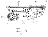
Fig. 1 in der ausgefahrenen Stellung, und - Fig. 4
- eine Seitenansicht einer weiteren Ausführungsform der erfindungsgemäßen Wäge- und Sortiervorrichtung.
- Die in den
Fig. 1 - 3 dargestellte kombinierte Wäge- und Sortiervorrichtung umfasst eine Zuführplattform 11, eine Wägeplattform 13 und eine als Sortierplattform 15 ausgebildete Abführplattform. Die Plattformen 11, 13, 15 schließen unmittelbar aneinander an und überlappen nicht. Durch die Plattformen 11, 13, 15 ist eine ungewinkelte, durchgehende Auflageebene definiert, über die ein für die Plattformen 11, 13, 15 gemeinsames, geschlossenes Gurtförderband 17 bzw. Endlosförderband geführt ist. - Durch das gemeinsame Gurtförderband 17 werden unstetige Übergänge zwischen den einzelnen Plattformen 11, 13 und 13, 15 vermieden. Das von der Vorrichtung transportiertes Stückgut löst daher keine Erschütterungen aus, die ansonsten durch derartige Übergänge entstehen und die Genauigkeit einer Gewichtsbestimmung durch eine der Wägeplattform 13 zugeordnete Wägezelle 21 herabsetzen.
- Das Gurtförderband 17 wird durch einen Antrieb, insbesondere einen Trommelmotor 19, angetrieben. Der Antrieb 19 bzw. die Antriebswelle des Antriebs 19 ist unterhalb der Plattformen 11, 13, 15 und innerhalb der durch das Förderband 17 gebildeten Schleife angeordnet.
- Die Wägeplattform 13 ist mit der unterhalb der Wägeplattform 13 angeordneten Wägezelle 21 gekoppelt, die dazu ausgelegt ist, das Gewicht des sich über die Wägeplattform 13 dynamisch hinweg bewegenden Stückguts zu bestimmen. Die Wägezelle 21 ist über einen Querträger 23 an einer Rückwand 25 der Vorrichtung abgestützt bzw. fest gehaltert. Die Rückwand 25 wiederum ist an einem Gestell oder Rahmen der Vorrichtung gehaltert.
- Zum Antrieb des Endlosförderbands 17 umfasst der Trommelmotor 19 zwei Stift- oder Stachelräder 27, die in nicht dargestellte Transportlöcher eingreifen, die an den beiden Randseiten des Endlosförderbands 17 ausgebildet sind. Durch die formschlüssige Verbindung des Antriebs 19 mit dem Endlosförderband 17 kann ein Schlupf zwischen diesen beiden Komponenten ausgeschlossen werden.
- Die Sortierplattform 15 ist zweiteilig ausgebildet, d.h. die Sortierplattform 15 umfasst einen einlaufseitigen, der Wägeplattform 13 zugewandten Endabschnitt 29 und einen auslaufseitigen, der Wägeplattform 13 abgewandten Endabschnitt 31. Die beiden Endabschnitte 29, 31 besitzen jeweils eine kammartige Struktur, wobei die Zinken der beiden Endabschnitte 29, 31 komplementär zueinander ausgebildet sind, so dass die beiden Endabschnitte 29, 31 kämmend ineinander greifen können.
- Die beiden Endabschnitte 29, 31 der Sortierplattform 15 sind relativ zueinander bewegbar. Die Sortierplattform 15 ist teleskopisch ausziehbar. Hierbei ist der einlaufseitige Endabschnitt 29 fest und unverschiebbar an der Gesamtvorrichtung gehaltert. Der auslaufseitige Endabschnitt 31 hingegen ist in Förderrichtung 33 stufenlos verschiebbar bzw. verstellbar gelagert. Zur Realisierung der verschiebbaren Lagerung ist eine Laufrollenführung vorgesehen. Die Laufrollenführung umfasst zwei fest an der Vorrichtung gehalterte Schienen in Form von Rundstäben 35, von denen in
Fig. 3 lediglich ein Rundstab 35 erkennbar ist, und für jeden der beiden Rundstäbe 35 einen Laufrollenwagen 37 mit vier Laufrollen 39, die paarweise oberhalb und unterhalb des jeweiligen Rundstabs 35 angeordnet sind und mit diesem in Rollkontakt stehen. - Über den auslaufseitigen Endabschnitt 31 ist die Sortierplattform 15 zwischen der in den
Fig. 1a und2a gezeigten auseinander gezogenen Stellung und der in denFig. 1b und2b gezeigten zurückgezogenen Stellung verstellbar. Die Sortierplattform 15 ist damit in ihrer Länge verstellbar. In denFig. 1a und2a kann an die gezeigte Wäge- und Sortereinrichtung auslaufseitig ein weiteres Förderband anschließen, mit dem das über die Vorrichtung transportierte Stückgut an eine weitere Bearbeitungsstation übergeben werden kann. In der rückgezogenen Position des auslaufseitigen Endabschnitts 31 gemäß denFig. 1b und2b hingegen fällt das Stückgut aufgrund seiner Gewichtskraft nach unten und kann hierdurch sortiert bzw. aussortiert werden. - Da sich die Gesamtlänge der Vorrichtung beim Zurückziehen der Sortierplattform 15 bzw. beim Aussortieren eines Stückguts ändert, ist eine entsprechende Anpassung des Verlaufs des Endlosförderbands 17 bevorzugt. Diese Anpassung wird durch eine mit dem auslaufseitigen Endabschnitt 31 verbundene Umlenkrolle 41 erreicht, die in Bandrichtung zwischen dem auslaufseitigen Ende des auslaufseitigen Endabschnitts 31 und dem Antrieb 19 angeordnet ist. Durch die vorgegebene Anordnung des auslaufseitigen Endes des abgewandten Endabschnitts 31, der Umlenkrolle 41 und dem Trommelmotor 19 wird eine Längenänderung des Obertrums durch eine entsprechende Längenänderung der durch die Umlenkrolle 41 im Untertrum gebildeten Schleife ausgeglichen.
- Die beiden Umlenkpunkte für das Obertrum des Förderbands 17 werden durch das einlaufseitige Ende der Zuführplattform 11 und das auslaufseitige Ende des abgewandten Endabschnitts 31 gebildet. Diese beiden Enden sind jeweils nicht durch eine drehbare Umlenkrolle gebildet, sondern nicht-rotierend ausgebildet. Da in diesen Bereichen keine drehbeweglichen Teile vorgesehen sind, kann die Wäge- und Sortiervorrichtung einfach und schnell gereinigt werden.
- Die erfindungsgemäße Wäge- und Sortiervorrichtung erlaubt trotz Sortierens eine erschütterungsfreie und damit hochgenaue Bestimmung des Gewichts von Stückgut.
-
- 11
- Zuführplattform
- 13
- Wägeplattform
- 15
- Sortierplattform
- 17
- Förderband
- 19
- Antrieb
- 21
- Wägezelle
- 23
- Querträger
- 25
- Rückwand
- 27
- Stiftrad
- 29
- Endabschnitt
- 31
- Endabschnitt
- 33
- Förderrichtung
- 35
- Rundstab
- 37
- Laufrollenwaagen
- 39
- Laufrolle
- 41
- Umlenkrolle
Claims (9)
- Wäge- und Sortiervorrichtung für Stückgut, mit einer Zuführplattform (11), einer Wägeplattform (13) und einer Sortierplattform (15), wobei die Plattformen (11, 13, 15) mit einem gemeinsamen Förderband (17) versehen sind, wobei zum Sortieren des Stückguts die Sortierplattform (15) zwischen einer ausgefahrenen Stellung und einer eingefahrenen Stellung verstellbar und längenverstellbar ist.
- Wäge- und Sortiervorrichtung nach Anspruch 1,
dadurch gekennzeichnet,
dass die Sortierplattform (15) einen der Wägeplattform (13) zugewandten Endabschnitt (29) und einen der Wägeplattform (13) abgewandten Endabschnitt (31) umfasst, wobei der zugewandte Endabschnitt (29) fest an der Vorrichtung gehaltert und/oder der abgewandte Endabschnitt (31) bewegbar an der Vorrichtung geführt ist. - Wäge- und Sortiervorrichtung nach Anspruch 2,
dadurch gekennzeichnet,
dass die bewegbare Führung des abgewandten Endabschnitts (31) als Laufrollenführung ausgebildet ist. - Wäge- und Sortiervorrichtung nach Anspruch 3,
dadurch gekennzeichnet,
dass die Laufrollenführung eine mit dem abgewandten Endabschnitt (31) fest verbundene Laufrollenanordnung (39) umfasst, die entlang wenigstens einer Schiene (35) bewegbar ist. - Wäge- und Sortiervorrichtung nach einem der Ansprüche 2 bis 4,
dadurch gekennzeichnet,
dass der zugewandte Endabschnitt (29) und der abgewandte Endabschnitt (31) dazu ausgebildet sind, kämmend ineinander zu greifen. - Wäge- und Sortiervorrichtung nach einem der vorstehenden Ansprüche,
dadurch gekennzeichnet,
dass für die ausgefahrene Stellung und/oder die eingefahrene Stellung ein Sanftanlauf und/oder ein Sanftauslauf vorgesehen ist. - Wäge- und Sortiervorrichtung nach einem der vorstehenden Ansprüche,
dadurch gekennzeichnet,
dass das Förderband (17) ein- und auslaufseitig über nicht-rotierende Umlenkeinrichtungen (11, 31) geführt ist. - Wäge- und Sortiervorrichtung nach einem der vorstehenden Ansprüche,
dadurch gekennzeichnet,
dass zum Antrieb des Förderbands (17) wenigstens ein Stift- oder Stachelrad (27) vorgesehen ist, wobei das Förderband (17) hierfür, insbesondere ein- oder beidseitig randseitig, mit Transportlöchern versehen ist. - Wäge- und Sortiervorrichtung nach einem der vorstehenden Ansprüche,
dadurch gekennzeichnet,
dass eine der Wägeplattform (13) zugeordnete Wägezelle (21) fest an der Vorrichtung, insbesondere einem Rahmen oder Gestell der Vorrichtung gehaltert ist.
Applications Claiming Priority (1)
| Application Number | Priority Date | Filing Date | Title |
|---|---|---|---|
| DE102010019742A DE102010019742A1 (de) | 2010-05-07 | 2010-05-07 | Wäge- und Sortiervorrichtung |
Publications (2)
| Publication Number | Publication Date |
|---|---|
| EP2385356A1 EP2385356A1 (de) | 2011-11-09 |
| EP2385356B1 true EP2385356B1 (de) | 2019-08-28 |
Family
ID=44343693
Family Applications (1)
| Application Number | Title | Priority Date | Filing Date |
|---|---|---|---|
| EP11003709.0A Active EP2385356B1 (de) | 2010-05-07 | 2011-05-05 | Wäge- und Sortiervorrichtung |
Country Status (2)
| Country | Link |
|---|---|
| EP (1) | EP2385356B1 (de) |
| DE (1) | DE102010019742A1 (de) |
Cited By (1)
| Publication number | Priority date | Publication date | Assignee | Title |
|---|---|---|---|---|
| US12258217B2 (en) | 2023-05-15 | 2025-03-25 | Mettler-Toledo, LLC | Sorting device |
Families Citing this family (8)
| Publication number | Priority date | Publication date | Assignee | Title |
|---|---|---|---|---|
| DE102013102815C5 (de) * | 2013-03-18 | 2019-10-17 | Jörn Strauß | Wiegevorrichtung für Sortiermaschinen für Lebensmittel und Messverfahren für eine Wiegevorrichtung |
| CN105865609A (zh) * | 2016-06-20 | 2016-08-17 | 许昌市大力电机制造有限公司 | 一种自动化快速称重系统 |
| CN107421610A (zh) * | 2017-04-24 | 2017-12-01 | 哈尔滨理工大学 | 一种新型动态称重秤 |
| CN107617579B (zh) * | 2017-10-30 | 2024-04-12 | 湖北科德智能装备有限公司 | 一种自动化分拣线在线称重装置 |
| CN107757958A (zh) * | 2017-11-27 | 2018-03-06 | 舟山市岱山县晓苏微电机配件厂 | 注塑件自动化称重装袋装置 |
| CN112317349A (zh) * | 2020-10-30 | 2021-02-05 | 河南京联四合棉花科技有限责任公司 | 一种用于异类棉包筛选的装置 |
| CN115489824B (zh) * | 2022-09-07 | 2023-08-01 | 济南鑫顺源包装有限公司 | 一种高效装箱称重装置及其使用方法 |
| CN116539130A (zh) * | 2023-05-11 | 2023-08-04 | 合肥金果缘视觉科技有限公司 | 一种小果称重装置 |
Citations (9)
| Publication number | Priority date | Publication date | Assignee | Title |
|---|---|---|---|---|
| GB868962A (en) | 1956-05-29 | 1961-05-25 | George Pollard Dennis | Improvements in or relating to the feeding of granular materials capable of flowing |
| GB1545105A (en) * | 1976-05-04 | 1979-05-02 | Hi Speed Checkweigher Co | Apparatus for and method of processing articles |
| WO1990005285A1 (en) | 1988-11-11 | 1990-05-17 | Scanvaegt A/S | A weighing system, particularly a maritime weighing system |
| WO2002054025A1 (en) * | 2001-01-08 | 2002-07-11 | Seelen A/S | A method of weighing objects |
| WO2004043835A1 (en) | 2002-11-07 | 2004-05-27 | Siemens Aktiengesellschaft | Adjustable length conveyor bed |
| US20040176874A1 (en) | 1994-09-15 | 2004-09-09 | Scanvaegt A/S | Method and apparatus for weight controlled portioning of articles having non-uniform weight |
| DE10322504A1 (de) | 2003-05-19 | 2004-12-09 | Garvens Automation Gmbh | Verfahren und Vorrichtung zum Wiegen von Produkten |
| US20080060916A1 (en) | 2006-09-08 | 2008-03-13 | Tipper Tie, Inc. | Telescoping conveyor mechanisms that cooperate with packaging systems having clippers and related methods |
| JP2010012414A (ja) | 2008-07-03 | 2010-01-21 | Yamato Scale Co Ltd | 重量選別機 |
Family Cites Families (2)
| Publication number | Priority date | Publication date | Assignee | Title |
|---|---|---|---|---|
| US1545105A (en) * | 1921-01-08 | 1925-07-07 | Harry A Koenig | Fuel economizer |
| US5686653A (en) * | 1996-05-09 | 1997-11-11 | General Signal Corporation | System for checking the calibration of gravimetric feeders and belt scales |
-
2010
- 2010-05-07 DE DE102010019742A patent/DE102010019742A1/de not_active Withdrawn
-
2011
- 2011-05-05 EP EP11003709.0A patent/EP2385356B1/de active Active
Patent Citations (10)
| Publication number | Priority date | Publication date | Assignee | Title |
|---|---|---|---|---|
| GB868962A (en) | 1956-05-29 | 1961-05-25 | George Pollard Dennis | Improvements in or relating to the feeding of granular materials capable of flowing |
| GB1545105A (en) * | 1976-05-04 | 1979-05-02 | Hi Speed Checkweigher Co | Apparatus for and method of processing articles |
| WO1990005285A1 (en) | 1988-11-11 | 1990-05-17 | Scanvaegt A/S | A weighing system, particularly a maritime weighing system |
| US20040176874A1 (en) | 1994-09-15 | 2004-09-09 | Scanvaegt A/S | Method and apparatus for weight controlled portioning of articles having non-uniform weight |
| WO2002054025A1 (en) * | 2001-01-08 | 2002-07-11 | Seelen A/S | A method of weighing objects |
| WO2004043835A1 (en) | 2002-11-07 | 2004-05-27 | Siemens Aktiengesellschaft | Adjustable length conveyor bed |
| DE10322504A1 (de) | 2003-05-19 | 2004-12-09 | Garvens Automation Gmbh | Verfahren und Vorrichtung zum Wiegen von Produkten |
| US20070181349A1 (en) * | 2003-05-19 | 2007-08-09 | Harald Beck | Method and device for weighing products |
| US20080060916A1 (en) | 2006-09-08 | 2008-03-13 | Tipper Tie, Inc. | Telescoping conveyor mechanisms that cooperate with packaging systems having clippers and related methods |
| JP2010012414A (ja) | 2008-07-03 | 2010-01-21 | Yamato Scale Co Ltd | 重量選別機 |
Non-Patent Citations (1)
| Title |
|---|
| ANONYMOUS: "Rückziehbare Fördererhecks", DORNER CONVEYORS, 7 February 2010 (2010-02-07), pages 1 - 13, XP055738877 |
Cited By (1)
| Publication number | Priority date | Publication date | Assignee | Title |
|---|---|---|---|---|
| US12258217B2 (en) | 2023-05-15 | 2025-03-25 | Mettler-Toledo, LLC | Sorting device |
Also Published As
| Publication number | Publication date |
|---|---|
| DE102010019742A1 (de) | 2011-11-10 |
| EP2385356A1 (de) | 2011-11-09 |
Similar Documents
| Publication | Publication Date | Title |
|---|---|---|
| EP2385356B1 (de) | Wäge- und Sortiervorrichtung | |
| EP0658499B1 (de) | Teleskopförderbahn zum Fördern und Vermessen von Stückgut | |
| EP2265523B1 (de) | Vorrichtung zum fördern von produkten | |
| EP2691324B1 (de) | Speichervorrichtung | |
| EP2938544B1 (de) | Etikettiervorrichtung | |
| EP1464595A2 (de) | Fördersystem, insbesondere eine Flughafen-Gepäckförderanlage, für Behälter | |
| DE102014117392A1 (de) | Fördervorrichtung | |
| DE102004007590B4 (de) | Dynamischer Puffer | |
| DE202015100131U1 (de) | Vorrichtung zum Transportieren und Wenden von Stückgut | |
| DE3812756A1 (de) | Vorrichtung zum aufnehmen von stueckguetern | |
| DE1951598B2 (de) | Ausweichspur für eine Arbeitsvorrichtung enthaltende Fertigungsstraßen | |
| EP3000753A1 (de) | Rollenhalterung für eine Transporteinrichtung | |
| DE102011052445A1 (de) | Sortierer | |
| EP3066035B1 (de) | Waage mit einem klappbaren waagentisch | |
| EP0665421A1 (de) | Stückgutförderer (Sorter) zum Sortieren von Stückgutteilen | |
| EP3370042B1 (de) | Mehrspurkontrollwaage | |
| EP2330059A1 (de) | Vertikalförderer | |
| EP2343519B2 (de) | Wägevorrichtung | |
| EP0407643A1 (de) | Vorrichtung zum Be- und Entladen, insbesondere von Schiffen mit Stückgut und/oder mit beladenen Paletten | |
| EP1452465A1 (de) | Fördersystem für Behälter, insbesondere eine Flughafen-Gepäckförderanlage | |
| DE202017004165U1 (de) | Vorrichtung zum Wiegen eines Produkts in einer Fertigungslinie | |
| DE112009000720B4 (de) | Fördervorrichtung für eine Anlage zur Keilverzinkung von Holzstücken | |
| DE69104121T2 (de) | Ladeeinrichtung für dynamische Wiegemaschinen. | |
| EP0805025A2 (de) | Druckgutfördervorrichtung zwischen Druckwerken | |
| DE279804C (de) |
Legal Events
| Date | Code | Title | Description |
|---|---|---|---|
| AK | Designated contracting states |
Kind code of ref document: A1 Designated state(s): AL AT BE BG CH CY CZ DE DK EE ES FI FR GB GR HR HU IE IS IT LI LT LU LV MC MK MT NL NO PL PT RO RS SE SI SK SM TR |
|
| AX | Request for extension of the european patent |
Extension state: BA ME |
|
| PUAI | Public reference made under article 153(3) epc to a published international application that has entered the european phase |
Free format text: ORIGINAL CODE: 0009012 |
|
| 17P | Request for examination filed |
Effective date: 20120427 |
|
| 17Q | First examination report despatched |
Effective date: 20160623 |
|
| STAA | Information on the status of an ep patent application or granted ep patent |
Free format text: STATUS: EXAMINATION IS IN PROGRESS |
|
| RAP1 | Party data changed (applicant data changed or rights of an application transferred) |
Owner name: BIZERBA SE & CO. KG |
|
| GRAP | Despatch of communication of intention to grant a patent |
Free format text: ORIGINAL CODE: EPIDOSNIGR1 |
|
| STAA | Information on the status of an ep patent application or granted ep patent |
Free format text: STATUS: GRANT OF PATENT IS INTENDED |
|
| INTG | Intention to grant announced |
Effective date: 20190320 |
|
| GRAS | Grant fee paid |
Free format text: ORIGINAL CODE: EPIDOSNIGR3 |
|
| GRAA | (expected) grant |
Free format text: ORIGINAL CODE: 0009210 |
|
| STAA | Information on the status of an ep patent application or granted ep patent |
Free format text: STATUS: THE PATENT HAS BEEN GRANTED |
|
| AK | Designated contracting states |
Kind code of ref document: B1 Designated state(s): AL AT BE BG CH CY CZ DE DK EE ES FI FR GB GR HR HU IE IS IT LI LT LU LV MC MK MT NL NO PL PT RO RS SE SI SK SM TR |
|
| REG | Reference to a national code |
Ref country code: GB Ref legal event code: FG4D Free format text: NOT ENGLISH |
|
| REG | Reference to a national code |
Ref country code: CH Ref legal event code: EP |
|
| REG | Reference to a national code |
Ref country code: DE Ref legal event code: R096 Ref document number: 502011016035 Country of ref document: DE |
|
| REG | Reference to a national code |
Ref country code: AT Ref legal event code: REF Ref document number: 1172978 Country of ref document: AT Kind code of ref document: T Effective date: 20190915 |
|
| REG | Reference to a national code |
Ref country code: IE Ref legal event code: FG4D Free format text: LANGUAGE OF EP DOCUMENT: GERMAN |
|
| REG | Reference to a national code |
Ref country code: NL Ref legal event code: MP Effective date: 20190828 |
|
| REG | Reference to a national code |
Ref country code: LT Ref legal event code: MG4D |
|
| PG25 | Lapsed in a contracting state [announced via postgrant information from national office to epo] |
Ref country code: LT Free format text: LAPSE BECAUSE OF FAILURE TO SUBMIT A TRANSLATION OF THE DESCRIPTION OR TO PAY THE FEE WITHIN THE PRESCRIBED TIME-LIMIT Effective date: 20190828 Ref country code: BG Free format text: LAPSE BECAUSE OF FAILURE TO SUBMIT A TRANSLATION OF THE DESCRIPTION OR TO PAY THE FEE WITHIN THE PRESCRIBED TIME-LIMIT Effective date: 20191128 Ref country code: SE Free format text: LAPSE BECAUSE OF FAILURE TO SUBMIT A TRANSLATION OF THE DESCRIPTION OR TO PAY THE FEE WITHIN THE PRESCRIBED TIME-LIMIT Effective date: 20190828 Ref country code: NL Free format text: LAPSE BECAUSE OF FAILURE TO SUBMIT A TRANSLATION OF THE DESCRIPTION OR TO PAY THE FEE WITHIN THE PRESCRIBED TIME-LIMIT Effective date: 20190828 Ref country code: FI Free format text: LAPSE BECAUSE OF FAILURE TO SUBMIT A TRANSLATION OF THE DESCRIPTION OR TO PAY THE FEE WITHIN THE PRESCRIBED TIME-LIMIT Effective date: 20190828 Ref country code: PT Free format text: LAPSE BECAUSE OF FAILURE TO SUBMIT A TRANSLATION OF THE DESCRIPTION OR TO PAY THE FEE WITHIN THE PRESCRIBED TIME-LIMIT Effective date: 20191230 Ref country code: NO Free format text: LAPSE BECAUSE OF FAILURE TO SUBMIT A TRANSLATION OF THE DESCRIPTION OR TO PAY THE FEE WITHIN THE PRESCRIBED TIME-LIMIT Effective date: 20191128 Ref country code: HR Free format text: LAPSE BECAUSE OF FAILURE TO SUBMIT A TRANSLATION OF THE DESCRIPTION OR TO PAY THE FEE WITHIN THE PRESCRIBED TIME-LIMIT Effective date: 20190828 |
|
| PG25 | Lapsed in a contracting state [announced via postgrant information from national office to epo] |
Ref country code: IS Free format text: LAPSE BECAUSE OF FAILURE TO SUBMIT A TRANSLATION OF THE DESCRIPTION OR TO PAY THE FEE WITHIN THE PRESCRIBED TIME-LIMIT Effective date: 20191228 Ref country code: LV Free format text: LAPSE BECAUSE OF FAILURE TO SUBMIT A TRANSLATION OF THE DESCRIPTION OR TO PAY THE FEE WITHIN THE PRESCRIBED TIME-LIMIT Effective date: 20190828 Ref country code: AL Free format text: LAPSE BECAUSE OF FAILURE TO SUBMIT A TRANSLATION OF THE DESCRIPTION OR TO PAY THE FEE WITHIN THE PRESCRIBED TIME-LIMIT Effective date: 20190828 Ref country code: GR Free format text: LAPSE BECAUSE OF FAILURE TO SUBMIT A TRANSLATION OF THE DESCRIPTION OR TO PAY THE FEE WITHIN THE PRESCRIBED TIME-LIMIT Effective date: 20191129 Ref country code: RS Free format text: LAPSE BECAUSE OF FAILURE TO SUBMIT A TRANSLATION OF THE DESCRIPTION OR TO PAY THE FEE WITHIN THE PRESCRIBED TIME-LIMIT Effective date: 20190828 Ref country code: ES Free format text: LAPSE BECAUSE OF FAILURE TO SUBMIT A TRANSLATION OF THE DESCRIPTION OR TO PAY THE FEE WITHIN THE PRESCRIBED TIME-LIMIT Effective date: 20190828 |
|
| PG25 | Lapsed in a contracting state [announced via postgrant information from national office to epo] |
Ref country code: TR Free format text: LAPSE BECAUSE OF FAILURE TO SUBMIT A TRANSLATION OF THE DESCRIPTION OR TO PAY THE FEE WITHIN THE PRESCRIBED TIME-LIMIT Effective date: 20190828 |
|
| PG25 | Lapsed in a contracting state [announced via postgrant information from national office to epo] |
Ref country code: DK Free format text: LAPSE BECAUSE OF FAILURE TO SUBMIT A TRANSLATION OF THE DESCRIPTION OR TO PAY THE FEE WITHIN THE PRESCRIBED TIME-LIMIT Effective date: 20190828 Ref country code: PL Free format text: LAPSE BECAUSE OF FAILURE TO SUBMIT A TRANSLATION OF THE DESCRIPTION OR TO PAY THE FEE WITHIN THE PRESCRIBED TIME-LIMIT Effective date: 20190828 Ref country code: IT Free format text: LAPSE BECAUSE OF FAILURE TO SUBMIT A TRANSLATION OF THE DESCRIPTION OR TO PAY THE FEE WITHIN THE PRESCRIBED TIME-LIMIT Effective date: 20190828 Ref country code: EE Free format text: LAPSE BECAUSE OF FAILURE TO SUBMIT A TRANSLATION OF THE DESCRIPTION OR TO PAY THE FEE WITHIN THE PRESCRIBED TIME-LIMIT Effective date: 20190828 Ref country code: RO Free format text: LAPSE BECAUSE OF FAILURE TO SUBMIT A TRANSLATION OF THE DESCRIPTION OR TO PAY THE FEE WITHIN THE PRESCRIBED TIME-LIMIT Effective date: 20190828 |
|
| REG | Reference to a national code |
Ref country code: DE Ref legal event code: R026 Ref document number: 502011016035 Country of ref document: DE |
|
| PG25 | Lapsed in a contracting state [announced via postgrant information from national office to epo] |
Ref country code: SM Free format text: LAPSE BECAUSE OF FAILURE TO SUBMIT A TRANSLATION OF THE DESCRIPTION OR TO PAY THE FEE WITHIN THE PRESCRIBED TIME-LIMIT Effective date: 20190828 Ref country code: CZ Free format text: LAPSE BECAUSE OF FAILURE TO SUBMIT A TRANSLATION OF THE DESCRIPTION OR TO PAY THE FEE WITHIN THE PRESCRIBED TIME-LIMIT Effective date: 20190828 Ref country code: SK Free format text: LAPSE BECAUSE OF FAILURE TO SUBMIT A TRANSLATION OF THE DESCRIPTION OR TO PAY THE FEE WITHIN THE PRESCRIBED TIME-LIMIT Effective date: 20190828 Ref country code: IS Free format text: LAPSE BECAUSE OF FAILURE TO SUBMIT A TRANSLATION OF THE DESCRIPTION OR TO PAY THE FEE WITHIN THE PRESCRIBED TIME-LIMIT Effective date: 20200224 |
|
| PLBI | Opposition filed |
Free format text: ORIGINAL CODE: 0009260 |
|
| 26 | Opposition filed |
Opponent name: METTLER-TOLEDO GMBH Effective date: 20200528 |
|
| PLAX | Notice of opposition and request to file observation + time limit sent |
Free format text: ORIGINAL CODE: EPIDOSNOBS2 |
|
| PG2D | Information on lapse in contracting state deleted |
Ref country code: IS |
|
| PG25 | Lapsed in a contracting state [announced via postgrant information from national office to epo] |
Ref country code: SI Free format text: LAPSE BECAUSE OF FAILURE TO SUBMIT A TRANSLATION OF THE DESCRIPTION OR TO PAY THE FEE WITHIN THE PRESCRIBED TIME-LIMIT Effective date: 20190828 |
|
| PLBB | Reply of patent proprietor to notice(s) of opposition received |
Free format text: ORIGINAL CODE: EPIDOSNOBS3 |
|
| PG25 | Lapsed in a contracting state [announced via postgrant information from national office to epo] |
Ref country code: MC Free format text: LAPSE BECAUSE OF FAILURE TO SUBMIT A TRANSLATION OF THE DESCRIPTION OR TO PAY THE FEE WITHIN THE PRESCRIBED TIME-LIMIT Effective date: 20190828 |
|
| REG | Reference to a national code |
Ref country code: BE Ref legal event code: MM Effective date: 20200531 |
|
| PG25 | Lapsed in a contracting state [announced via postgrant information from national office to epo] |
Ref country code: LU Free format text: LAPSE BECAUSE OF NON-PAYMENT OF DUE FEES Effective date: 20200505 |
|
| PG25 | Lapsed in a contracting state [announced via postgrant information from national office to epo] |
Ref country code: IE Free format text: LAPSE BECAUSE OF NON-PAYMENT OF DUE FEES Effective date: 20200505 |
|
| PG25 | Lapsed in a contracting state [announced via postgrant information from national office to epo] |
Ref country code: BE Free format text: LAPSE BECAUSE OF NON-PAYMENT OF DUE FEES Effective date: 20200531 |
|
| PG25 | Lapsed in a contracting state [announced via postgrant information from national office to epo] |
Ref country code: MT Free format text: LAPSE BECAUSE OF FAILURE TO SUBMIT A TRANSLATION OF THE DESCRIPTION OR TO PAY THE FEE WITHIN THE PRESCRIBED TIME-LIMIT Effective date: 20190828 Ref country code: CY Free format text: LAPSE BECAUSE OF FAILURE TO SUBMIT A TRANSLATION OF THE DESCRIPTION OR TO PAY THE FEE WITHIN THE PRESCRIBED TIME-LIMIT Effective date: 20190828 |
|
| PG25 | Lapsed in a contracting state [announced via postgrant information from national office to epo] |
Ref country code: MK Free format text: LAPSE BECAUSE OF FAILURE TO SUBMIT A TRANSLATION OF THE DESCRIPTION OR TO PAY THE FEE WITHIN THE PRESCRIBED TIME-LIMIT Effective date: 20190828 |
|
| REG | Reference to a national code |
Ref country code: DE Ref legal event code: R100 Ref document number: 502011016035 Country of ref document: DE |
|
| PLCK | Communication despatched that opposition was rejected |
Free format text: ORIGINAL CODE: EPIDOSNREJ1 |
|
| PLBN | Opposition rejected |
Free format text: ORIGINAL CODE: 0009273 |
|
| STAA | Information on the status of an ep patent application or granted ep patent |
Free format text: STATUS: OPPOSITION REJECTED |
|
| 27O | Opposition rejected |
Effective date: 20221018 |
|
| PGFP | Annual fee paid to national office [announced via postgrant information from national office to epo] |
Ref country code: DE Payment date: 20250519 Year of fee payment: 15 |
|
| PGFP | Annual fee paid to national office [announced via postgrant information from national office to epo] |
Ref country code: GB Payment date: 20250522 Year of fee payment: 15 |
|
| PGFP | Annual fee paid to national office [announced via postgrant information from national office to epo] |
Ref country code: FR Payment date: 20250521 Year of fee payment: 15 |
|
| PGFP | Annual fee paid to national office [announced via postgrant information from national office to epo] |
Ref country code: CH Payment date: 20250601 Year of fee payment: 15 |
|
| PGFP | Annual fee paid to national office [announced via postgrant information from national office to epo] |
Ref country code: AT Payment date: 20250519 Year of fee payment: 15 |