EP2385263A2 - A high - strength sleeve yoke having leaning surfaces with downsized chipping surface - Google Patents
A high - strength sleeve yoke having leaning surfaces with downsized chipping surface Download PDFInfo
- Publication number
- EP2385263A2 EP2385263A2 EP11165119A EP11165119A EP2385263A2 EP 2385263 A2 EP2385263 A2 EP 2385263A2 EP 11165119 A EP11165119 A EP 11165119A EP 11165119 A EP11165119 A EP 11165119A EP 2385263 A2 EP2385263 A2 EP 2385263A2
- Authority
- EP
- European Patent Office
- Prior art keywords
- sleeve yoke
- leaning
- lobe
- yoke
- leaning surfaces
- Prior art date
- Legal status (The legal status is an assumption and is not a legal conclusion. Google has not performed a legal analysis and makes no representation as to the accuracy of the status listed.)
- Granted
Links
- 238000000034 method Methods 0.000 claims abstract description 8
- 238000004519 manufacturing process Methods 0.000 claims 1
- 238000003754 machining Methods 0.000 description 5
- 210000001061 forehead Anatomy 0.000 description 4
- 230000015572 biosynthetic process Effects 0.000 description 1
- 229940076664 close up Drugs 0.000 description 1
Images

Classifications
-
- F—MECHANICAL ENGINEERING; LIGHTING; HEATING; WEAPONS; BLASTING
- F16—ENGINEERING ELEMENTS AND UNITS; GENERAL MEASURES FOR PRODUCING AND MAINTAINING EFFECTIVE FUNCTIONING OF MACHINES OR INSTALLATIONS; THERMAL INSULATION IN GENERAL
- F16D—COUPLINGS FOR TRANSMITTING ROTATION; CLUTCHES; BRAKES
- F16D3/00—Yielding couplings, i.e. with means permitting movement between the connected parts during the drive
- F16D3/16—Universal joints in which flexibility is produced by means of pivots or sliding or rolling connecting parts
- F16D3/26—Hooke's joints or other joints with an equivalent intermediate member to which each coupling part is pivotally or slidably connected
- F16D3/38—Hooke's joints or other joints with an equivalent intermediate member to which each coupling part is pivotally or slidably connected with a single intermediate member with trunnions or bearings arranged on two axes perpendicular to one another
- F16D3/382—Hooke's joints or other joints with an equivalent intermediate member to which each coupling part is pivotally or slidably connected with a single intermediate member with trunnions or bearings arranged on two axes perpendicular to one another constructional details of other than the intermediate member
- F16D3/387—Fork construction; Mounting of fork on shaft; Adapting shaft for mounting of fork
-
- F—MECHANICAL ENGINEERING; LIGHTING; HEATING; WEAPONS; BLASTING
- F16—ENGINEERING ELEMENTS AND UNITS; GENERAL MEASURES FOR PRODUCING AND MAINTAINING EFFECTIVE FUNCTIONING OF MACHINES OR INSTALLATIONS; THERMAL INSULATION IN GENERAL
- F16D—COUPLINGS FOR TRANSMITTING ROTATION; CLUTCHES; BRAKES
- F16D2250/00—Manufacturing; Assembly
-
- F—MECHANICAL ENGINEERING; LIGHTING; HEATING; WEAPONS; BLASTING
- F16—ENGINEERING ELEMENTS AND UNITS; GENERAL MEASURES FOR PRODUCING AND MAINTAINING EFFECTIVE FUNCTIONING OF MACHINES OR INSTALLATIONS; THERMAL INSULATION IN GENERAL
- F16D—COUPLINGS FOR TRANSMITTING ROTATION; CLUTCHES; BRAKES
- F16D3/00—Yielding couplings, i.e. with means permitting movement between the connected parts during the drive
- F16D3/02—Yielding couplings, i.e. with means permitting movement between the connected parts during the drive adapted to specific functions
- F16D3/06—Yielding couplings, i.e. with means permitting movement between the connected parts during the drive adapted to specific functions specially adapted to allow axial displacement
Definitions
- the invention relates to leaning surfaces that provide fixing of the sleeve yoke to the broach bench for the process of cutting spline threads in the inner section of the sleeve yoke of the cardan shaft in cardan shafts applications.
- the said invention relates to the leaning surfaces wherein the sleeve yoke is attached to the broach bench for the process of cutting spline threads in the inner section of the sleeve yoke, comprising heights formed on the lobes of the said sleeve yoke and the leaning surfaces formed on these heights.
- the process of fixing on the bench occurs with the leaning surface given to the body part.
- the leaning surface is contained in circular form on the body. Because the leaning surface in circular form is close to the operation area of the sheathing felt, when the sliding length is kept fixed, the axis distance can not remain under a certain value. For this reason, the leaning surface in circular form can not meet the requirement for extremely short cardan shaft need.
- the cardan shaft has lower strength in the zone of leaning area because there does not exist thread form beneath the lobes, the leaning surface is created on the external diameter of the body.
- Purpose of the invention is, to cut threads in spline form for the interior part of the sliding cardan shaft in the cardan shaft applications, to create forehead surface (flat area) needed for connecting the shaft desired to be obtained as very short statured in the cardan shafts, appropriately for ergonomic use.
- a purpose of the invention is to eliminate a negative situation that may occur in the sheathing felt by providing formation of the sheathing felt of the forehead surface, desired to be in the external perimeter, in a farther area than the operation area of the sheathing felt of the forehead surface.
- Another purpose of the invention is to provide machining in less amount because only the processing of the beneath the lobes when the forehead surface is being created beneath the lobe.
- Another purpose of the invention is to provide the use of smaller scale raw, processable piece because the invention eliminates the requirement of leaving the margin of chipping (machining) in the external diameter of the shaft.
- the process can be realised with a lighter, (unprocessed) piece.
- a further purpose of the invention on the other hand is to obtain higher strength and stiffness values in the machined areas of the processed cardan shaft.
- the invention relates to the leaning surfaces to cut the spline threads, in the interior part of the sleeve yoke, wherein the sleeve yoke is attached to the broach bench, the heights created on the lobes of the said sleeve yoke and the leaning surfaces on these heights are realised.
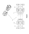
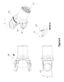
- FIG-1 a front and perspective view of the sliding shaft according to the invention, having leaning surface placed under lobe, in the cardan shaft system is illustrated.
- the sleeve yoke (11) forms the female sliding piece; the forked sliding shaft (18) forms the male sliding piece.
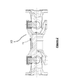
- Figure-2 a two - dimensional view of the complete cardan shaft (10) in semi-partial cross-sectional form is illustrated.
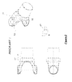
- FIG-3 a side, top, perspective and partial cross-sectional detail views of the sleeve yoke (11) presently used in the prior art are illustrated.
- the leaning surface (17) of the sleeve yoke (11) used in the prior art is formed on the full circumferential surface (16) and a circular leaning surface (17) is obtained.
- Circular form of the leaning surface (17) on the body, hat is on full circumferential surface (16) is seen. (See Figure-3). Because the leaning surface (17) in circular form is close to the operation area of the sheathing felt (19) seen in Figure-2, the axis distance does not remain below a certain value when the sliding length is kept fixed.
- the leaning surface in circular form can not meet the requirement in the very short cardan shaft need.
- both a loss of time occurs and excessive amounts of chip are removed because chip is removed from all the perimeter surface.
- a further negative aspect of its on the other hand is that it leads to reduction in the strength of the cardan shaft (10).
- the piece is heavier because it is known that chip will be removed through the sleeve yoke (11) having an unprocessed raw piece position in Figure-3 in the prior art.
- Figure-5 there is a view of the structure, wherein the chips are removed with an angle of 360 degrees from the full circumferential surface (16) of the sleeve yoke (11) belonging to the prior art and circular leaning surface (17) is obtained.
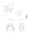
- Purpose of the creation of the heights (14) on the other hand is to fix the sleeve yoke (11) to the broach bench to create the spline threads (12) seen in Figure-6.
- Leaning surfaces (15) created on the heights (14) have a shorter distance of chip removal in comparison with the leaning surfaces used in the prior art. Because the leaning surface (15) is away from the full circumferential surface (16), yet is close to the lobe (13) area, it provides creation of the sheathing felt (19) in a farther area than the operation area, eliminating also the negative situations that may emerge in the sheathing felt (19).
Landscapes
- Engineering & Computer Science (AREA)
- General Engineering & Computer Science (AREA)
- Mechanical Engineering (AREA)
- Turbine Rotor Nozzle Sealing (AREA)
- Sliding-Contact Bearings (AREA)
- Milling, Broaching, Filing, Reaming, And Others (AREA)
- Shafts, Cranks, Connecting Bars, And Related Bearings (AREA)
- Braking Arrangements (AREA)
Abstract
Description
- The invention relates to leaning surfaces that provide fixing of the sleeve yoke to the broach bench for the process of cutting spline threads in the inner section of the sleeve yoke of the cardan shaft in cardan shafts applications.
- The said invention relates to the leaning surfaces wherein the sleeve yoke is attached to the broach bench for the process of cutting spline threads in the inner section of the sleeve yoke, comprising heights formed on the lobes of the said sleeve yoke and the leaning surfaces formed on these heights.
- In the existing applications, the process of fixing on the bench occurs with the leaning surface given to the body part. The leaning surface is contained in circular form on the body. Because the leaning surface in circular form is close to the operation area of the sheathing felt, when the sliding length is kept fixed, the axis distance can not remain under a certain value. For this reason, the leaning surface in circular form can not meet the requirement for extremely short cardan shaft need.
- Because the leaning surface created on the body part used in the prior art needs to be processed in circular form on all the perimeter, it is necessary to remove large amounts of chips.
- In the prior art, larger diameter body, that is unprocessed piece to be processed slower is used because margin of chipping is left for the purpose of creating a leaning surface on the external diameter of the body.
- Also, with regard to the prior art; the cardan shaft has lower strength in the zone of leaning area because there does not exist thread form beneath the lobes, the leaning surface is created on the external diameter of the body.
- In the search for patents about the cardan shafts, some applications concerning the prior art were found. Among those applications is the application with no
TR2006/06222U - Purpose of the invention is, to cut threads in spline form for the interior part of the sliding cardan shaft in the cardan shaft applications, to create forehead surface (flat area) needed for connecting the shaft desired to be obtained as very short statured in the cardan shafts, appropriately for ergonomic use.
- A purpose of the invention is to eliminate a negative situation that may occur in the sheathing felt by providing formation of the sheathing felt of the forehead surface, desired to be in the external perimeter, in a farther area than the operation area of the sheathing felt of the forehead surface.
- Another purpose of the invention is to provide machining in less amount because only the processing of the beneath the lobes when the forehead surface is being created beneath the lobe.
- Another purpose of the invention is to provide the use of smaller scale raw, processable piece because the invention eliminates the requirement of leaving the margin of chipping (machining) in the external diameter of the shaft. Thus, the process can be realised with a lighter, (unprocessed) piece.
- A further purpose of the invention on the other hand is to obtain higher strength and stiffness values in the machined areas of the processed cardan shaft.
- To meet the above mentioned objectives, the invention relates to the leaning surfaces to cut the spline threads, in the interior part of the sleeve yoke, wherein the sleeve yoke is attached to the broach bench, the heights created on the lobes of the said sleeve yoke and the leaning surfaces on these heights are realised.
-
- Figure- 1 is a front and perspective view, in the cardan shaft system, of the sleeve yoke according to the invention, having a leaning surface placed under the lobe.
- Figure- 2 is an example view of the sleeve yoke according to the invention, for the use of a short sleeve yoke.
- Figure-3 are the views of the sleeve yoke used in the prior art, wherein the leaning surface is not in created, processed form yet.
- Figure- 4 are the views of the sleeve yoke used in the prior art, wherein the leaning surface placed under the lobe is not in created, processed form yet.
- Figure- 5 are the views of the sleeve yoke used in the prior art, wherein the leaning surface is in created, processed (machined) form.
- Figure- 6 are the views of the sleeve yoke used in the prior art, wherein the leaning surface placed under the lobe is in created, processed (machined) form.
-
- 10.
- Cardan shaft
- 11.
- Sleeve yoke
- 12.
- Spline threads
- 13.
- Lobe
- 14.
- Height
- 15.
- Leaning surface
- 16.
- Full circumferential surface
- 17.
- Circular leaning surface
- 18.
- Forked sliding shaft
- 19.
- Sheathing felt
- 20.
- Forked flange
- In Figure-1, a front and perspective view of the sliding shaft according to the invention, having leaning surface placed under lobe, in the cardan shaft system is illustrated. The sleeve yoke (11) forms the female sliding piece; the forked sliding shaft (18) forms the male sliding piece. In Figure-2 on the other hand a two - dimensional view of the complete cardan shaft (10) in semi-partial cross-sectional form is illustrated.
- In Figure-3, a side, top, perspective and partial cross-sectional detail views of the sleeve yoke (11) presently used in the prior art are illustrated. As seen in Figure-5, the leaning surface (17) of the sleeve yoke (11) used in the prior art is formed on the full circumferential surface (16) and a circular leaning surface (17) is obtained. Circular form of the leaning surface (17) on the body, hat is on full circumferential surface (16) is seen. (See Figure-3). Because the leaning surface (17) in circular form is close to the operation area of the sheathing felt (19) seen in Figure-2, the axis distance does not remain below a certain value when the sliding length is kept fixed. Therefore, the leaning surface in circular form can not meet the requirement in the very short cardan shaft need. At the same time, both a loss of time occurs and excessive amounts of chip are removed because chip is removed from all the perimeter surface. A further negative aspect of its on the other hand is that it leads to reduction in the strength of the cardan shaft (10). For example, the piece is heavier because it is known that chip will be removed through the sleeve yoke (11) having an unprocessed raw piece position in Figure-3 in the prior art. In Figure-5 on the other hand there is a view of the structure, wherein the chips are removed with an angle of 360 degrees from the full circumferential surface (16) of the sleeve yoke (11) belonging to the prior art and circular leaning surface (17) is obtained.
- In Figure-6, differently from the prior art, leaning surfaces (15) have been created with an arc angle of 360° as much as the lobe (13) j - distance with an arc angle of 90° to 150°, without having to remove chips with an arc angle of 360° from full circumferential the surface (16) of the said sleeve yoke (11). In Figure-4, a view of the unprocessed raw piece, that is, the sleeve yoke (11) is illustrated. To create the leaning surfaces (15), the height (14) seen in Figure-4 are created on both lobes (13). Purpose of the creation of the heights (14) on the other hand is to fix the sleeve yoke (11) to the broach bench to create the spline threads (12) seen in Figure-6. Leaning surfaces (15) created on the heights (14) have a shorter distance of chip removal in comparison with the leaning surfaces used in the prior art. Because the leaning surface (15) is away from the full circumferential surface (16), yet is close to the lobe (13) area, it provides creation of the sheathing felt (19) in a farther area than the operation area, eliminating also the negative situations that may emerge in the sheathing felt (19). At the same time, the processing is carried out with a lighter raw (unprocessed) piece, also a sleeve yoke (11) having high strength and stiffness is obtained. (For a close- up view of the leaning surface (15), see detail-a).
Claims (4)
- The invention relates to the leaning surfaces wherein the sleeve yoke (11) is attached to the broach bench for the process of cutting spline threads (12) in the inner section of the sleeve yoke (11); and is characterised in that; it comprises heights (14) formed on the lobe (13) of the said sleeve yoke and the leaning surfaces (15) formed on these heights (14).
- A sleeve yoke according to Claim 1, and is characterised in that; the said sleeve yoke (11) comprises leaning surfaces (15) away from the full circumferential surface (16); yet, have a processing surface as much as the lobe (13) j - distance.
- The invention is the production method for the concerning the leaning surfaces wherein the sleeve yoke (11) is attached to the broach bench for the process of cutting spline threads (12) in the interior part of the sleeve yoke (11), and is characterised in that; leaning surfaces (15) are created with an arc angle of 90° to 150° as much as the lobe (13) j - distance, without having to remove chips with an arc angle of 360° from the full circular surface (16) of the said sleeve yoke (11).
- Method according to Claim 3, and is characterised in that; leaning surfaces (15) shaped up in form of an arc are created in the place wherein the full circumferential surface (16) of the sleeve yoke (11) ends and the lobe (13) form begins.
Applications Claiming Priority (1)
| Application Number | Priority Date | Filing Date | Title |
|---|---|---|---|
| TR2010/03605A TR201003605A2 (en) | 2010-05-06 | 2010-05-06 | A high-strength sliding fork with reduced cutting surfaces. |
Publications (3)
| Publication Number | Publication Date |
|---|---|
| EP2385263A2 true EP2385263A2 (en) | 2011-11-09 |
| EP2385263A3 EP2385263A3 (en) | 2012-12-19 |
| EP2385263B1 EP2385263B1 (en) | 2016-08-03 |
Family
ID=44352108
Family Applications (1)
| Application Number | Title | Priority Date | Filing Date |
|---|---|---|---|
| EP11165119.6A Active EP2385263B1 (en) | 2010-05-06 | 2011-05-06 | A high-strength sleeve yoke having fixing surfaces with reduced machining chipping surface and corresponding production method |
Country Status (4)
| Country | Link |
|---|---|
| EP (1) | EP2385263B1 (en) |
| ES (1) | ES2589788T3 (en) |
| PL (1) | PL2385263T3 (en) |
| TR (1) | TR201003605A2 (en) |
Cited By (1)
| Publication number | Priority date | Publication date | Assignee | Title |
|---|---|---|---|---|
| WO2019099757A1 (en) * | 2017-11-16 | 2019-05-23 | Dana Automotive Systems Group, Llc | Tube yokes and method of forming tube yokes |
Family Cites Families (4)
| Publication number | Priority date | Publication date | Assignee | Title |
|---|---|---|---|---|
| ES2003937A6 (en) * | 1986-11-06 | 1988-12-01 | Daumal Castellon Melchor | Fork for cardan joints and method of forming same |
| US5580184A (en) * | 1995-04-28 | 1996-12-03 | The Torrington Company | Angular adjustable clamp yoke |
| JP2001074060A (en) * | 1999-09-06 | 2001-03-23 | Riken Tanzou Kk | Sliding yoke and manufacture thereof |
| DE10261114B4 (en) * | 2002-12-20 | 2012-04-05 | Spicer Gelenkwellenbau Gmbh | Universal joint with a securing element |
-
2010
- 2010-05-06 TR TR2010/03605A patent/TR201003605A2/en unknown
-
2011
- 2011-05-06 ES ES11165119.6T patent/ES2589788T3/en active Active
- 2011-05-06 PL PL11165119.6T patent/PL2385263T3/en unknown
- 2011-05-06 EP EP11165119.6A patent/EP2385263B1/en active Active
Cited By (1)
| Publication number | Priority date | Publication date | Assignee | Title |
|---|---|---|---|---|
| WO2019099757A1 (en) * | 2017-11-16 | 2019-05-23 | Dana Automotive Systems Group, Llc | Tube yokes and method of forming tube yokes |
Also Published As
| Publication number | Publication date |
|---|---|
| EP2385263B1 (en) | 2016-08-03 |
| ES2589788T3 (en) | 2016-11-16 |
| TR201003605A2 (en) | 2011-09-21 |
| EP2385263A3 (en) | 2012-12-19 |
| PL2385263T3 (en) | 2016-12-30 |
Similar Documents
| Publication | Publication Date | Title |
|---|---|---|
| CN109909519B (en) | Cutting insert for reverse turning | |
| JP5939001B2 (en) | drill | |
| CN104209565B (en) | A kind of three sword forming cutters | |
| US11014174B2 (en) | Multi-flute end mill | |
| EP2910326B1 (en) | Stacked material tool and method for machining | |
| US20180094604A1 (en) | Piston crown having conical valve seat and method for manufacturing a piston crown having a conically shaped valve seat | |
| CN206028838U (en) | Three sword wolfram steel shaping swoves | |
| EP2385263A2 (en) | A high - strength sleeve yoke having leaning surfaces with downsized chipping surface | |
| CN107921556B (en) | Cutting tool, tool body and method for producing a tool body | |
| CN208976932U (en) | High performance precision forming tank round nose cutter | |
| CN104511604A (en) | Multifunctional cutter | |
| CN207289036U (en) | A kind of high-precision built-up broach of retainer | |
| CN109692978A (en) | The compound lathe tool of synchro converter ring Vehicle Processing and synchro converter ring processing method | |
| CN204770845U (en) | Cutter at processing vallecular cavity part inner wall corner and base angle | |
| CN104249185B (en) | Slotting cutter | |
| CN204108421U (en) | A kind of fluted drill | |
| CN202639460U (en) | Formed cutter for processing surface of workpiece | |
| JP5651353B2 (en) | Shaving mold | |
| CN106624094A (en) | Novel conicity ball mill | |
| CN204818256U (en) | Three surface broachs | |
| CN105710426B (en) | A kind of processing method of large size semi-precise milling cutter for concave groove | |
| CN104815996B (en) | Polyester plastics part processing method | |
| CN104815997B (en) | Boring method for small-hole plastic part | |
| KR200335553Y1 (en) | Finishing Tool for end of pipes | |
| KR101381741B1 (en) | Broaching tool |
Legal Events
| Date | Code | Title | Description |
|---|---|---|---|
| AK | Designated contracting states |
Kind code of ref document: A2 Designated state(s): AL AT BE BG CH CY CZ DE DK EE ES FI FR GB GR HR HU IE IS IT LI LT LU LV MC MK MT NL NO PL PT RO RS SE SI SK SM TR |
|
| AX | Request for extension of the european patent |
Extension state: BA ME |
|
| PUAI | Public reference made under article 153(3) epc to a published international application that has entered the european phase |
Free format text: ORIGINAL CODE: 0009012 |
|
| PUAL | Search report despatched |
Free format text: ORIGINAL CODE: 0009013 |
|
| AK | Designated contracting states |
Kind code of ref document: A3 Designated state(s): AL AT BE BG CH CY CZ DE DK EE ES FI FR GB GR HR HU IE IS IT LI LT LU LV MC MK MT NL NO PL PT RO RS SE SI SK SM TR |
|
| AX | Request for extension of the european patent |
Extension state: BA ME |
|
| RIC1 | Information provided on ipc code assigned before grant |
Ipc: F16D 3/38 20060101AFI20121112BHEP |
|
| 17P | Request for examination filed |
Effective date: 20130613 |
|
| RAP1 | Party data changed (applicant data changed or rights of an application transferred) |
Owner name: TIRSAN KARDAN SANAYI VE TICARET ANONIM SIRKETI |
|
| GRAP | Despatch of communication of intention to grant a patent |
Free format text: ORIGINAL CODE: EPIDOSNIGR1 |
|
| INTG | Intention to grant announced |
Effective date: 20160421 |
|
| GRAS | Grant fee paid |
Free format text: ORIGINAL CODE: EPIDOSNIGR3 |
|
| GRAA | (expected) grant |
Free format text: ORIGINAL CODE: 0009210 |
|
| AK | Designated contracting states |
Kind code of ref document: B1 Designated state(s): AL AT BE BG CH CY CZ DE DK EE ES FI FR GB GR HR HU IE IS IT LI LT LU LV MC MK MT NL NO PL PT RO RS SE SI SK SM TR |
|
| REG | Reference to a national code |
Ref country code: GB Ref legal event code: FG4D |
|
| REG | Reference to a national code |
Ref country code: CH Ref legal event code: EP Ref country code: AT Ref legal event code: REF Ref document number: 817538 Country of ref document: AT Kind code of ref document: T Effective date: 20160815 |
|
| REG | Reference to a national code |
Ref country code: IE Ref legal event code: FG4D |
|
| REG | Reference to a national code |
Ref country code: NL Ref legal event code: FP |
|
| REG | Reference to a national code |
Ref country code: DE Ref legal event code: R096 Ref document number: 602011028726 Country of ref document: DE |
|
| REG | Reference to a national code |
Ref country code: SE Ref legal event code: TRGR |
|
| REG | Reference to a national code |
Ref country code: ES Ref legal event code: FG2A Ref document number: 2589788 Country of ref document: ES Kind code of ref document: T3 Effective date: 20161116 |
|
| REG | Reference to a national code |
Ref country code: LT Ref legal event code: MG4D |
|
| REG | Reference to a national code |
Ref country code: AT Ref legal event code: MK05 Ref document number: 817538 Country of ref document: AT Kind code of ref document: T Effective date: 20160803 |
|
| PG25 | Lapsed in a contracting state [announced via postgrant information from national office to epo] |
Ref country code: NO Free format text: LAPSE BECAUSE OF FAILURE TO SUBMIT A TRANSLATION OF THE DESCRIPTION OR TO PAY THE FEE WITHIN THE PRESCRIBED TIME-LIMIT Effective date: 20161103 Ref country code: FI Free format text: LAPSE BECAUSE OF FAILURE TO SUBMIT A TRANSLATION OF THE DESCRIPTION OR TO PAY THE FEE WITHIN THE PRESCRIBED TIME-LIMIT Effective date: 20160803 Ref country code: LT Free format text: LAPSE BECAUSE OF FAILURE TO SUBMIT A TRANSLATION OF THE DESCRIPTION OR TO PAY THE FEE WITHIN THE PRESCRIBED TIME-LIMIT Effective date: 20160803 Ref country code: HR Free format text: LAPSE BECAUSE OF FAILURE TO SUBMIT A TRANSLATION OF THE DESCRIPTION OR TO PAY THE FEE WITHIN THE PRESCRIBED TIME-LIMIT Effective date: 20160803 Ref country code: IS Free format text: LAPSE BECAUSE OF FAILURE TO SUBMIT A TRANSLATION OF THE DESCRIPTION OR TO PAY THE FEE WITHIN THE PRESCRIBED TIME-LIMIT Effective date: 20161203 Ref country code: RS Free format text: LAPSE BECAUSE OF FAILURE TO SUBMIT A TRANSLATION OF THE DESCRIPTION OR TO PAY THE FEE WITHIN THE PRESCRIBED TIME-LIMIT Effective date: 20160803 |
|
| PG25 | Lapsed in a contracting state [announced via postgrant information from national office to epo] |
Ref country code: AT Free format text: LAPSE BECAUSE OF FAILURE TO SUBMIT A TRANSLATION OF THE DESCRIPTION OR TO PAY THE FEE WITHIN THE PRESCRIBED TIME-LIMIT Effective date: 20160803 Ref country code: GR Free format text: LAPSE BECAUSE OF FAILURE TO SUBMIT A TRANSLATION OF THE DESCRIPTION OR TO PAY THE FEE WITHIN THE PRESCRIBED TIME-LIMIT Effective date: 20161104 Ref country code: PT Free format text: LAPSE BECAUSE OF FAILURE TO SUBMIT A TRANSLATION OF THE DESCRIPTION OR TO PAY THE FEE WITHIN THE PRESCRIBED TIME-LIMIT Effective date: 20161205 Ref country code: LV Free format text: LAPSE BECAUSE OF FAILURE TO SUBMIT A TRANSLATION OF THE DESCRIPTION OR TO PAY THE FEE WITHIN THE PRESCRIBED TIME-LIMIT Effective date: 20160803 |
|
| PG25 | Lapsed in a contracting state [announced via postgrant information from national office to epo] |
Ref country code: EE Free format text: LAPSE BECAUSE OF FAILURE TO SUBMIT A TRANSLATION OF THE DESCRIPTION OR TO PAY THE FEE WITHIN THE PRESCRIBED TIME-LIMIT Effective date: 20160803 Ref country code: RO Free format text: LAPSE BECAUSE OF FAILURE TO SUBMIT A TRANSLATION OF THE DESCRIPTION OR TO PAY THE FEE WITHIN THE PRESCRIBED TIME-LIMIT Effective date: 20160803 |
|
| REG | Reference to a national code |
Ref country code: DE Ref legal event code: R097 Ref document number: 602011028726 Country of ref document: DE |
|
| PG25 | Lapsed in a contracting state [announced via postgrant information from national office to epo] |
Ref country code: CZ Free format text: LAPSE BECAUSE OF FAILURE TO SUBMIT A TRANSLATION OF THE DESCRIPTION OR TO PAY THE FEE WITHIN THE PRESCRIBED TIME-LIMIT Effective date: 20160803 Ref country code: DK Free format text: LAPSE BECAUSE OF FAILURE TO SUBMIT A TRANSLATION OF THE DESCRIPTION OR TO PAY THE FEE WITHIN THE PRESCRIBED TIME-LIMIT Effective date: 20160803 Ref country code: SM Free format text: LAPSE BECAUSE OF FAILURE TO SUBMIT A TRANSLATION OF THE DESCRIPTION OR TO PAY THE FEE WITHIN THE PRESCRIBED TIME-LIMIT Effective date: 20160803 Ref country code: SK Free format text: LAPSE BECAUSE OF FAILURE TO SUBMIT A TRANSLATION OF THE DESCRIPTION OR TO PAY THE FEE WITHIN THE PRESCRIBED TIME-LIMIT Effective date: 20160803 Ref country code: BG Free format text: LAPSE BECAUSE OF FAILURE TO SUBMIT A TRANSLATION OF THE DESCRIPTION OR TO PAY THE FEE WITHIN THE PRESCRIBED TIME-LIMIT Effective date: 20161103 Ref country code: BE Free format text: LAPSE BECAUSE OF FAILURE TO SUBMIT A TRANSLATION OF THE DESCRIPTION OR TO PAY THE FEE WITHIN THE PRESCRIBED TIME-LIMIT Effective date: 20160803 |
|
| REG | Reference to a national code |
Ref country code: FR Ref legal event code: PLFP Year of fee payment: 7 |
|
| PLBE | No opposition filed within time limit |
Free format text: ORIGINAL CODE: 0009261 |
|
| STAA | Information on the status of an ep patent application or granted ep patent |
Free format text: STATUS: NO OPPOSITION FILED WITHIN TIME LIMIT |
|
| 26N | No opposition filed |
Effective date: 20170504 |
|
| PG25 | Lapsed in a contracting state [announced via postgrant information from national office to epo] |
Ref country code: SI Free format text: LAPSE BECAUSE OF FAILURE TO SUBMIT A TRANSLATION OF THE DESCRIPTION OR TO PAY THE FEE WITHIN THE PRESCRIBED TIME-LIMIT Effective date: 20160803 Ref country code: LU Free format text: LAPSE BECAUSE OF NON-PAYMENT OF DUE FEES Effective date: 20170531 |
|
| REG | Reference to a national code |
Ref country code: CH Ref legal event code: PL |
|
| PG25 | Lapsed in a contracting state [announced via postgrant information from national office to epo] |
Ref country code: MC Free format text: LAPSE BECAUSE OF FAILURE TO SUBMIT A TRANSLATION OF THE DESCRIPTION OR TO PAY THE FEE WITHIN THE PRESCRIBED TIME-LIMIT Effective date: 20160803 |
|
| REG | Reference to a national code |
Ref country code: IE Ref legal event code: MM4A |
|
| PG25 | Lapsed in a contracting state [announced via postgrant information from national office to epo] |
Ref country code: LI Free format text: LAPSE BECAUSE OF NON-PAYMENT OF DUE FEES Effective date: 20170531 Ref country code: CH Free format text: LAPSE BECAUSE OF NON-PAYMENT OF DUE FEES Effective date: 20170531 |
|
| PG25 | Lapsed in a contracting state [announced via postgrant information from national office to epo] |
Ref country code: LU Free format text: LAPSE BECAUSE OF NON-PAYMENT OF DUE FEES Effective date: 20170506 |
|
| PG25 | Lapsed in a contracting state [announced via postgrant information from national office to epo] |
Ref country code: IE Free format text: LAPSE BECAUSE OF NON-PAYMENT OF DUE FEES Effective date: 20170506 |
|
| REG | Reference to a national code |
Ref country code: FR Ref legal event code: PLFP Year of fee payment: 8 |
|
| PG25 | Lapsed in a contracting state [announced via postgrant information from national office to epo] |
Ref country code: MT Free format text: LAPSE BECAUSE OF NON-PAYMENT OF DUE FEES Effective date: 20170506 |
|
| PG25 | Lapsed in a contracting state [announced via postgrant information from national office to epo] |
Ref country code: AL Free format text: LAPSE BECAUSE OF FAILURE TO SUBMIT A TRANSLATION OF THE DESCRIPTION OR TO PAY THE FEE WITHIN THE PRESCRIBED TIME-LIMIT Effective date: 20160803 |
|
| PG25 | Lapsed in a contracting state [announced via postgrant information from national office to epo] |
Ref country code: HU Free format text: LAPSE BECAUSE OF FAILURE TO SUBMIT A TRANSLATION OF THE DESCRIPTION OR TO PAY THE FEE WITHIN THE PRESCRIBED TIME-LIMIT; INVALID AB INITIO Effective date: 20110506 |
|
| PG25 | Lapsed in a contracting state [announced via postgrant information from national office to epo] |
Ref country code: CY Free format text: LAPSE BECAUSE OF NON-PAYMENT OF DUE FEES Effective date: 20160803 |
|
| PG25 | Lapsed in a contracting state [announced via postgrant information from national office to epo] |
Ref country code: MK Free format text: LAPSE BECAUSE OF FAILURE TO SUBMIT A TRANSLATION OF THE DESCRIPTION OR TO PAY THE FEE WITHIN THE PRESCRIBED TIME-LIMIT Effective date: 20160803 |
|
| PG25 | Lapsed in a contracting state [announced via postgrant information from national office to epo] |
Ref country code: TR Free format text: LAPSE BECAUSE OF FAILURE TO SUBMIT A TRANSLATION OF THE DESCRIPTION OR TO PAY THE FEE WITHIN THE PRESCRIBED TIME-LIMIT Effective date: 20160803 |
|
| PGFP | Annual fee paid to national office [announced via postgrant information from national office to epo] |
Ref country code: NL Payment date: 20240508 Year of fee payment: 14 |
|
| PGFP | Annual fee paid to national office [announced via postgrant information from national office to epo] |
Ref country code: GB Payment date: 20240503 Year of fee payment: 14 |
|
| PGFP | Annual fee paid to national office [announced via postgrant information from national office to epo] |
Ref country code: DE Payment date: 20240521 Year of fee payment: 14 |
|
| PGFP | Annual fee paid to national office [announced via postgrant information from national office to epo] |
Ref country code: ES Payment date: 20240605 Year of fee payment: 14 |
|
| PGFP | Annual fee paid to national office [announced via postgrant information from national office to epo] |
Ref country code: IT Payment date: 20240521 Year of fee payment: 14 Ref country code: FR Payment date: 20240529 Year of fee payment: 14 |
|
| PGFP | Annual fee paid to national office [announced via postgrant information from national office to epo] |
Ref country code: PL Payment date: 20240502 Year of fee payment: 14 |
|
| PGFP | Annual fee paid to national office [announced via postgrant information from national office to epo] |
Ref country code: SE Payment date: 20240505 Year of fee payment: 14 |