EP2385222A1 - Turbine - Google Patents
Turbine Download PDFInfo
- Publication number
- EP2385222A1 EP2385222A1 EP09839233A EP09839233A EP2385222A1 EP 2385222 A1 EP2385222 A1 EP 2385222A1 EP 09839233 A EP09839233 A EP 09839233A EP 09839233 A EP09839233 A EP 09839233A EP 2385222 A1 EP2385222 A1 EP 2385222A1
- Authority
- EP
- European Patent Office
- Prior art keywords
- casing
- turbine
- circular
- stator
- support portion
- Prior art date
- Legal status (The legal status is an assumption and is not a legal conclusion. Google has not performed a legal analysis and makes no representation as to the accuracy of the status listed.)
- Withdrawn
Links
Images



Classifications
-
- F—MECHANICAL ENGINEERING; LIGHTING; HEATING; WEAPONS; BLASTING
- F01—MACHINES OR ENGINES IN GENERAL; ENGINE PLANTS IN GENERAL; STEAM ENGINES
- F01D—NON-POSITIVE DISPLACEMENT MACHINES OR ENGINES, e.g. STEAM TURBINES
- F01D25/00—Component parts, details, or accessories, not provided for in, or of interest apart from, other groups
- F01D25/24—Casings; Casing parts, e.g. diaphragms, casing fastenings
- F01D25/246—Fastening of diaphragms or stator-rings
-
- F—MECHANICAL ENGINEERING; LIGHTING; HEATING; WEAPONS; BLASTING
- F01—MACHINES OR ENGINES IN GENERAL; ENGINE PLANTS IN GENERAL; STEAM ENGINES
- F01D—NON-POSITIVE DISPLACEMENT MACHINES OR ENGINES, e.g. STEAM TURBINES
- F01D25/00—Component parts, details, or accessories, not provided for in, or of interest apart from, other groups
- F01D25/24—Casings; Casing parts, e.g. diaphragms, casing fastenings
- F01D25/243—Flange connections; Bolting arrangements
-
- F—MECHANICAL ENGINEERING; LIGHTING; HEATING; WEAPONS; BLASTING
- F01—MACHINES OR ENGINES IN GENERAL; ENGINE PLANTS IN GENERAL; STEAM ENGINES
- F01D—NON-POSITIVE DISPLACEMENT MACHINES OR ENGINES, e.g. STEAM TURBINES
- F01D25/00—Component parts, details, or accessories, not provided for in, or of interest apart from, other groups
- F01D25/24—Casings; Casing parts, e.g. diaphragms, casing fastenings
- F01D25/26—Double casings; Measures against temperature strain in casings
- F01D25/265—Vertically split casings; Clamping arrangements therefor
-
- F—MECHANICAL ENGINEERING; LIGHTING; HEATING; WEAPONS; BLASTING
- F05—INDEXING SCHEMES RELATING TO ENGINES OR PUMPS IN VARIOUS SUBCLASSES OF CLASSES F01-F04
- F05D—INDEXING SCHEME FOR ASPECTS RELATING TO NON-POSITIVE-DISPLACEMENT MACHINES OR ENGINES, GAS-TURBINES OR JET-PROPULSION PLANTS
- F05D2230/00—Manufacture
- F05D2230/60—Assembly methods
- F05D2230/64—Assembly methods using positioning or alignment devices for aligning or centring, e.g. pins
- F05D2230/642—Assembly methods using positioning or alignment devices for aligning or centring, e.g. pins using maintaining alignment while permitting differential dilatation
-
- F—MECHANICAL ENGINEERING; LIGHTING; HEATING; WEAPONS; BLASTING
- F05—INDEXING SCHEMES RELATING TO ENGINES OR PUMPS IN VARIOUS SUBCLASSES OF CLASSES F01-F04
- F05D—INDEXING SCHEME FOR ASPECTS RELATING TO NON-POSITIVE-DISPLACEMENT MACHINES OR ENGINES, GAS-TURBINES OR JET-PROPULSION PLANTS
- F05D2250/00—Geometry
- F05D2250/20—Three-dimensional
- F05D2250/23—Three-dimensional prismatic
- F05D2250/232—Three-dimensional prismatic conical
Definitions
- the present invention relates a turbine, and it relates in particular to a turbine that obtains a rotational force using a high-temperature working fluid.
- Patent Literature 1 Known turbines that obtain a rotational force using a high-temperature working fluid include, for example, the disclosure in Patent Literature 1.
- Turbines that obtain a rotational force using a high-temperature working fluid include those provided with a vertically divided (pot-shaped) casing that is divided into two portions in a longitudinal direction (front-back direction) and a support portion that supports a stator-blade holding ring disposed inside the casing.
- the conventional support portion is formed so that a mortar-shaped circular-truncated cone portion that connects a flange portion and the stator-blade holding ring becomes vertically asymmetrical, that is, so that its length (width) becomes gradually longer from a top portion (upper portion) side to a bottom portion (lower portion) side.
- the surface area (pressure-receiving area) of a lower-half portion becomes larger than the surface area (pressure-receiving area) of an upper-half portion and, due to a difference (pressure difference) between pressure that acts on a high-pressure side surface of the support portion (more specifically, the circular-truncated cone portion) and pressure that acts on a low-pressure side surface of the support portion (more specifically, the circular-truncated cone portion), the support portion (more specifically, the circular-truncated cone portion) may become deformed (tilted) so as to bow down.
- a high-temperature working fluid for example, combustion gas or steam
- a high-temperature working fluid that passes through the interior of the stator-blade holding ring causes an asymmetrical differential thermal expansion in the support portion (more specifically, the circular-truncated cone portion), and this may cause the support portion (more specifically, the circular-truncated cone portion) to become deformed (inclined) so as to bow down.
- the present invention has been conceived in light of the above-described circumstances, and an object thereof is to provide a turbine that is capable of preventing deforming (tilting) of a support portion (more specifically, the circular-truncated cone portion) due to a pressure difference or differential thermal expansion.
- a turbine according to a first aspect of the present invention is a turbine that is provided with a vertically divided casing that is divided into two portions in a longitudinal direction; and a support portion that supports a stator-blade holding ring disposed in the casing, wherein, the support portion is provided with a flange portion that is secured between a joining surface of one portion of the casing and a joining surface of the other portion of the casing, being sandwiched therebetween, and a circular-truncated cone portion that connects the flange portion and the stator-blade holding ring, and wherein a thick plate portion having a greater plate thickness than the plate thickness of the flange portion and the stator-blade holding ring is provided between the flange portion located at a lower-half portion and the stator-blade holding ring.
- the rigidity of the support portion as a whole is increased (enhanced) by the thick plate portion provided (formed) in the support portion, it is possible to prevent deforming (tilting) of the support portion (more specifically, the circular-truncated cone portion) caused by a difference (pressure difference) between pressure that acts on a high-pressure side surface of the support portion (more specifically, the circular-truncated cone portion) and pressure that acts on a low-pressure side surface of the support portion (more specifically the circular-truncated cone portion).
- the thick plate portion provided (formed) in the support portion, it is possible to prevent asymmetrical differential thermal expansion of the support portion (more specifically, the circular-truncated cone portion) caused by having a high-temperature working fluid (for example, combustion gas or steam) pass through the inside of the stator-blade holding ring, and it is also possible to prevent deforming (tilting) of the support portion (more specifically, the circular-truncated cone portion) caused by this asymmetrical differential thermal expansion.
- a high-temperature working fluid for example, combustion gas or steam
- a tip clearance between tips (distal ends) of the turbine blades and an inner circumferential surface of the stator-blade holding ring can be held constant, thereby making it possible to reduce leakage (tip leakage) from the tips of the turbine blades; and thus, turbine efficiency (performance) can be enhanced, and contact between the tips of the turbine blades and the inner circumferential surface of the stator-blade holding ring can also be prevented, making it possible to prevent damage to and breakage of the turbine blades and turbine nozzles. Accordingly, the reliability of the turbine can be enhanced.
- a turbine according to a second aspect of the present invention is a turbine that is provided with a vertically divided casing that is divided into two portions in a longitudinal direction; and a support portion that supports a stator-blade holding ring disposed in the casing, wherein, the support portion is provided with a flange portion that is secured between a joining surface of one portion of the casing and a joining surface of the other portion of the casing, being sandwiched therebetween, and a circular-truncated cone portion that connects the flange portion and the stator-blade holding ring, and wherein the flange portion is formed so that the plate thickness thereof gradually increases from a radially outer side toward a radially inner side thereof, and so that the joining surfaces of the casing coincide with the joining surfaces of the flange portion.
- the flange portion provided (formed) in the support portion increases (enhances) the rigidity of the support portion as a whole; therefore, it is possible to prevent deforming (tilting) of the support portion (more specifically, the circular-truncated cone portion) caused by a difference (pressure difference) between pressure that acts on a high-pressure side surface of the support portion (more specifically, the circular-truncated coned portion) and pressure that acts on a low-pressure side surface of the support portion (more specifically, the circular-truncated cone portion).
- the flange portion provided (formed) in the support portion, it is possible to prevent asymmetrical differential thermal expansion of the support portion (more specifically, the circular-truncated cone portion) caused by having a high-temperature working fluid (for example, combustion gas or steam) pass through the inside of the stator-blade holding ring, and it is also possible to prevent deforming (tilting) of the support portion (more specifically, the circular-truncated cone portion) caused by this asymmetrical differential thermal expansion.
- a high-temperature working fluid for example, combustion gas or steam
- a tip clearance between the tips (distal ends) of the turbine blades and the inner circumferential surface of the stator-blade holding ring can be held constant, thereby making it possible to reduce leakage (tip leakage) from the tips of the turbine blades; and thus, the turbine efficiency (performance) can be enhanced, and contact between the tips of the turbine blades and the inner circumferential surface of the stator-blade holding ring can also be prevented, making it possible to prevent damage to and breakage of the turbine blades and turbine nozzles. Accordingly, the reliability of the turbine can be enhanced.
- the joining surface of the front casing and the joining surface of the flange portion are individually formed as tapered surfaces (formed like a circular truncated cone); therefore, when assembling the casing, coupling alignment (centering) between the casing and the support portion can be easily performed, thereby making it possible to shorten the processing time required for assembling the casing.
- a turbine according a third aspect of the present invention is a turbine that is provided with a vertically divided casing that is divided into two portions in a longitudinal direction; and a support portion that supports a stator-blade holding ring disposed in the casing, wherein, the support portion is provided with a flange portion that is secured between a joining surface of one portion of the casing and a joining surface of the other portion of the casing, being sandwiched therebetween, and a circular-truncated cone portion that connects the flange portion and the stator-blade holding ring, and wherein a ring fabricated using a high thermal expansion material as a constituent is provided between an outer circumferential surface of the circular-truncated cone portion and an inner circumferential surface of the front casing.
- the ring expands at a greater thermal expansion rate than the casing and the support portion, thereby causing an outer circumferential surface of the circular-truncated cone portion and an inner circumferential surface (circumferential surface on radially inner side) of the ring to come into close contact with each other, which also causes an inner circumferential surface of the casing and an outer circumferential surface (circumferential surface on radially outer side) of the ring to come into close contact with each other; therefore, a space formed between the outer circumferential surface of the circular-truncated cone portion and the inner circumferential surface of the casing is completely filled with the ring, without any gap.
- a high-temperature working fluid for example, combustion gas or steam
- a tip clearance between the tips (distal ends) of the turbine blades and the inner circumferential surface of the stator-blade holding ring can be held constant, thereby making it possible to reduce the leakage (tip leakage) from the tips of the turbine blades; and thus, the turbine efficiency (performance) can be enhanced, and contact between the tips of the turbine blades and the inner circumferential surface of the stator-blade holding ring can also be prevented, making it possible to prevent damage to and breakage of the turbine blades and turbine nozzles. Accordingly, the reliability of the turbine can be enhanced.
- a turbine according to a fourth aspect of the present invention is a turbine that is provided with a vertically divided casing that is divided into two portions in a longitudinal direction; and a support portion that supports a stator-blade holding ring disposed in the casing, wherein, the support portion is provided with a flange portion that is secured between a joining surface of one portion of the casing and a joining surface of the other portion of the casing, being sandwiched therebetween, and a circular-truncated cone portion that connects the flange portion and the stator-blade holding ring, and wherein the circular-truncated cone portion is formed so as to have a fixed length in a circumferential direction.
- the circular-truncated cone portion is provided (formed) so as to have a fixed length (width) over the circumferential direction, it is possible to prevent asymmetrical differential thermal expansion of the support portion (more specifically, the circular-truncated cone portion), as well as deforming (tilting) of the support portion (more specifically, the circular-truncated cone portion) that are caused by a difference (pressure difference) between pressure that acts on a high-pressure side surface of the support portion (more specifically, the circular-truncated coned portion) and pressure that acts on a low-pressure side surface of the support portion (more specifically, the circular-truncated cone portion) and by having a high-temperature working fluid (for example, combustion gas or steam) pass through the inside of the stator-blade holding ring.
- a high-temperature working fluid for example, combustion gas or steam
- a tip clearance between tips (distal ends) of the turbine blades and the inner circumferential surface of the stator-blade holding ring can be held constant, thereby making it possible to reduce leakage (tip leakage) from the tips of the turbine blades; and thus, the turbine efficiency (performance) can be enhanced, and contact between the tips of the turbine blades and the inner circumferential surface of the stator-blade holding ring can also be prevented, making it possible to prevent damage to and breakage of the turbine blades and the turbine nozzles. Accordingly, the reliability of the turbine can be enhanced.
- the plate thickness at a lower-half portion of the circular-truncated portion be greater than the plate thickness at an upper-half portion of the circular-truncated portion.
- the rigidity of the support portion can be further enhanced; the tip clearance between the tips (distal ends) of the turbine blades and the inner circumferential surface of the stator-blade holding ring can be held constant, thereby making it possible to further reduce a leakage (tip leakage) from the tips of the turbine blades; and thus, the turbine efficiency (performance) can be further enhanced, and contact between the tips of the turbine blades and the inner circumferential surface of the stator-blade holding ring can also be prevented, making it possible to prevent damage to and breakage of the turbine blades and turbine nozzles. Accordingly, the reliability of the turbine can be further enhanced.
- an advantage is afforded in that it is possible to prevent deforming (tilting) of a support portion (more specifically, a circular-truncated cone portion) due to a pressure difference or a differential thermal expansion.
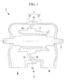
- FIG. 1 shows a lateral sectional view of a turbine according to the first embodiment of the present invention
- Fig. 2 is a perspective sectional view of relevant portions of the turbine shown in Fig. 1
- Fig. 3 is a longitudinal sectional view of relevant portions of a support portion shown in Fig. 1 .
- a turbine 1 obtains a rotational force using, for example, high-temperature steam from a boiler (not shown); using this rotational force, drives a generator connected via a rotation shaft; and, as shown in Fig. 1 , is configured to include a turbine rotor 2 and a casing 3 as main components.
- the casing 3 is a vertically divided casing that is divided into two portions in a front-back direction (left-right direction in Fig.1 ) and is provided with a front casing 3a located on the right side in Fig. 1 and a rear casing 3b located on the left side in Fig. 1 .
- flange portions 9a of a support portion 9 that supports a stator-blade holding ring 8 are configured so as to be sandwiched between the front casing 3a and the rear casing 3b.
- the stator-blade holding ring 8 is disposed so as to surround the turbine rotor 2 and the turbine blades on the radially outer side, and, at its inner circumferential portion, a plurality of turbine nozzles (stator blades) are attached along the circumferential direction.
- the support portion 9 includes the flange portions 9a, circular-truncated cone portions 9b, and thick plate portions 9c.
- the flange portions 9a are plate-like members that are ring-like (doughnut-like) in plan view, having a fixed thickness and a fixed length (width) over the circumferential direction, and are secured, via a plurality of bolts (fastening members), between a joining surface of the front casing 3a (see Fig. 1 ) and a joining surface of the rear casing 3b (see Fig. 1 ) in an attachable/detachable manner.
- the circular-truncated cone portions 9b are mortar-like members that have a fixed thickness and a fixed length (width) over the circumferential direction; that protrude backward (from a front casing 3a side toward a rear casing 3b side); that connect the flange portions 9a and the stator-blade holding ring 8 at upper-half portions thereof; and that connect the thick plate portions 9c and the stator-blade holding ring 8 at lower-half portions thereof.
- the thick plate portions 9c are plate-like members that are crescent-like in plan view and that are formed so that the plate thickness thereof is greater than the plate thickness of the flange portions 9a and the circular-truncated cone portions 9b.
- the "plate thickness" of the thick plate portions 9c refers to a thickness in a direction parallel to a direction in which a turbine axis (axis in the longitudinal direction: rotational axis) of the turbine 1 (see Fig. 1 ) extends, which is indicated by a reference sign C in Fig. 2 ; in other words, it refers to a thickness in the left-right direction in Fig. 1 .
- the thick plate portions 9c provided (formed) in the support portion 9 increase (enhance) the rigidity of the support portion 9 as a whole; therefore, it is possible to prevent deforming (tilting) of the support portion 9 (more specifically, the circular-truncated cone portions 9b) caused by a difference (pressure difference) between pressure that acts on a high-pressure side (right side in Fig. 1 ) surface of the support portion 9 (more specifically, the circular-truncated coned portions 9b) and pressure that acts on a low-pressure side (left side in Fig. 1 ) surface of the support portion 9 (more specifically, the circular-truncated cone portions 9b).
- the thick plate portions 9c provided (formed) in the support portion 9 it is possible to prevent an asymmetrical differential thermal expansion of the support portion 9 (more specifically, the circular-truncated cone portions 9b) caused by having a high-temperature working fluid (for example, combustion gas or steam) pass through the inside of the stator-blade holding ring 8, as well as deforming (tilting) of the support portion 9 (more specifically, the circular-truncated cone portions 9b) caused by this asymmetrical differential thermal expansion.
- a high-temperature working fluid for example, combustion gas or steam
- a tip clearance between tips (distal ends) of the turbine blades and an inner circumferential surface of the stator-blade holding ring 8 can be held constant, thereby making it possible to reduce leakage (tip leakage) from the tips of the turbine blades; and thus, turbine efficiency (performance) can be enhanced and contact between the tips of the turbine blades and the inner circumferential surface of the stator-blade holding ring 8 can also be prevented, making it possible to prevent damage to and breakage of the turbine blades and the turbine nozzles. Accordingly, the reliability of the turbine 1 can be enhanced.
- FIG. 4 is an enlarged view of relevant portions of a turbine according to this embodiment.
- a turbine 21 according to this embodiment differs from the above-described first embodiment in that a support portion 22 is provided instead of the support portion 9. Because other constituent components are the same as those in the above-described first embodiment, descriptions of those constituent components will be omitted.
- the support portion 22 is provided with flange portions 22a and circular-truncated cone portions 22b.
- the flange portions 22a are plate-like members that are ring-like (doughnut-like) in plan view, having a fixed thickness and a fixed length (width) over the circumferential direction, and are secured, via a plurality of bolts (fastening members), between the joining surface of the front casing 3a and the joining surface of the rear casing 3b in an attachable/detachable manner.
- the circular-truncated cone portions 22b are mortar-like members that have a fixed thickness over the circumferential direction; that protrude backward (from the front casing 3a side toward the rear casing 3b side); and that connect the flange portions 22a and the stator-blade holding ring 8 in the circumferential direction.
- outer circumferential surfaces (circumferential surfaces at the radially outer side) 23 of the circular-truncated cone portions 22b are provided (formed) so as to be located in the vicinity of inner circumferential surfaces 24 of the front casing 3a and the rear casing 3b, that is, so as to be located as close as possible to the inner circumferential surfaces 24 of the front casing 3a and the rear casing 3b.
- the turbine 21 With the turbine 21 according to this embodiment, deforming (tilting) of the support portion 22 (more specifically, the circular-truncated cone portions 22b) caused by a pressure difference or differential thermal expansion can be suppressed to the minimum (significantly reduced); therefore, the tip clearance between the tips (distal ends) of the turbine blades and the stator-blade holding ring 8 can be held substantially constant, thereby making it possible to reduce the leakage (tip leakage) from the tips of the turbine blades; and thus, the turbine efficiency (performance) can be enhanced and contact between the tips of the turbine blades and the inner circumferential surface of the stator-blade hooding ring 8 can also be prevented, making it possible to prevent damage to and breakage of the turbine blades and the turbine nozzles. Accordingly, the reliability of the turbine 21 can be enhanced.
- FIG. 5 is an enlarged view of relevant portions of a turbine according to this embodiment.
- a turbine 31 according to this embodiment differs from the above-described first embodiment in that a support portion 32 is provided instead of the support portion 9. Because other constituent components are the same as those in the above-described first embodiment, descriptions of those constituent components will be omitted.
- the support portion 32 is provided with flange portions 32a and circular-truncated cone portions 32b.
- the flange portions 32a are plate-like members that are ring-like (doughnut-like) in plan view and that are formed so as to gradually increase in thickness from a radially outer side toward a radially inner side as well as to have a fixed length (width) in the circumferential direction, and are secured, via a plurality of bolts (fastening members), between the joining surface of the front casing 3a and the joining surface of the rear casing 3b in an attachable/detachable manner. Note that, as shown in Fig.
- the joining surfaces 33 of the front casing 3a in this embodiment are provided (formed) so as to coincide with (come in contact with) joining surfaces 34 of the flange portions 32a.
- the circular-truncated cone portions 32b are mortar-like members that have a fixed thickness over the circumferential direction; that protrude backward (from the front casing 3a side toward the rear casing 3b side); and that connect the flange portions 32a and the stator-blade holding ring 8.
- the flange portions 32a provided (formed) in the support portion 32 increase (enhance) the rigidity of the support portion 32 as a whole; therefore, it is possible to prevent deforming (tilting) of the support portion 32 (more specifically, the circular-truncated cone portions 32b) caused by a difference (pressure difference) between pressure that acts on a high-pressure side (right side in Fig. 5 ) surface of the support portion 32 (more specifically, the circular-truncated coned portions 32b) and pressure that acts on a low-pressure side (left side in Fig. 5 ) surface of the support portion 32 (more specifically, the circular-truncated cone portions 32b).
- the flange portions 32a provided (formed) in the support portion 32 it is possible to prevent asymmetrical differential thermal expansion of the support portion 32 (more specifically, the circular-truncated cone portions 32b) caused by having a high-temperature working fluid (for example, combustion gas or steam) pass through the inside of the stator-blade holding ring 8, as well as deforming (tilting) of the support portion 32 (more specifically, the circular-truncated cone portions 32b) caused by this asymmetrical differential thermal expansion.
- a high-temperature working fluid for example, combustion gas or steam
- the tip clearance between the tips (distal ends) of the turbine blades and the inner circumferential surface of the stator-blade holding ring 8 can be held constant, thereby making it possible to reduce leakage (tip leakage) from the tips of the turbine blades; and thus, the turbine efficiency (performance) can be enhanced, and contact between the tips of the turbine blades and the inner circumferential surface of the stator-blade holding ring 8 can also be prevented, making it possible to prevent damage to and breakage of the turbine blades and the turbine nozzles. Accordingly, the reliability of the turbine 31 can be enhanced.
- the joining surfaces 33 of the front casing 3a and the joining surfaces 34 of the flange portions 32a are individually formed as tapered surfaces (formed like a circular truncated cone); therefore, when assembling the casing 3, coupling alignment (centering) between the front casing 3a and the support portion 32 can be easily performed, thereby making it possible to shorten the processing time required for assembling the casing 3.
- FIG. 6 is an enlarged view of relevant portions of a turbine according to this embodiment.
- a turbine 41 according to this embodiment differs from the above-described second embodiment in that a ring 42 is provided between the outer circumferential surfaces 23 of the circular-truncated cone portions 22b and the inner circumferential surfaces 24 of the front casing 3a. Because other constituent components are the same as those in the above-described second embodiment, descriptions of those constituent components will be omitted.
- the ring 42 is a thin plate-like member that is ring-like (doughnut-like) in plan view, having a fixed thickness and a fixed length (width) over the circumferential direction, and is fabricated using a high-thermal-expansion material (for example, SUS304) as a constituent.
- a high-thermal-expansion material for example, SUS304
- the casing 3 and the support portion 22 are fabricated using, as constituents, metal materials (for example, alloys containing 2Cr) having lower thermal expansion rates than the ring 42.
- the ring 42 expands at a greater thermal expansion rate than the casing 3 and the support portion 22, thereby causing the outer circumferential surfaces 23 of the circular-truncated cone portions 22b and an inner circumferential surface (circumferential surface on radially inner side) of the ring 42 to come into close contact with each other, which also causes the inner circumferential surfaces 24 of the front casing 3a and an outer circumferential surface (circumferential surface on radially outer side) of the ring 42 to come into close contact with each other; therefore, a space formed between the outer circumferential surfaces 23 of the circular-truncated cone portions 22b and the inner circumferential surfaces 24 of the front casing 3a is completely filled with the ring 42, without any gap.
- a high-temperature working fluid for example, combustion gas or steam
- the support portion 22 (more specifically, the circular-truncated cone portions 22b) to deform (tilt) due to a pressure difference or differential thermal expansion during turbine operation
- deforming (tilting) of the support portion 22 is prevented by the ring 42 disposed (interposed) between the outer circumferential surfaces 23 of the circular-truncated cone portions 22b and the inner circumferential surfaces 24 of the front casing 3a.
- the turbine 42 because deforming (tilting) of the support portion 22 (more specifically, the circular-truncated cone portions 22b) due to a pressure difference or differential thermal expansion can be prevented, the tip clearance between the tips (distal ends) of the turbine blades and the inner circumferential surface of the stator-blade holding ring 8 can be held constant, thereby making it possible to reduce leakage (tip leakage) from the tips of the turbine blades; and thus, the turbine efficiency (performance) can be enhanced, and contact between the tips of the turbine blades and the inner circumferential surface of the stator-blade holding ring 8 can also be prevented, making it possible to prevent damage to and breakage of the turbine blades and the turbine nozzles. Accordingly, the reliability of the turbine 41 can be enhanced.
- FIG. 7 is a perspective sectional view of relevant portions of a turbine according to this embodiment.
- a turbine 51 according to this embodiment differs from the above-described first embodiment in that a support portion 52 is provided instead of the support portion 9. Because other constituent components are the same as those in the above-described first embodiment, descriptions of those constituent components will be omitted.
- the support portion 52 is provided with flange portions 52a and circular-truncated cone portions 52b.
- the flange portions 52a are plate-like members that are ring-like (doughnut-like) in plan view, having a fixed thickness and a fixed length (width) over the circumferential direction, and are secured, via a plurality of bolts (fastening members), between the joining surface of the front casing 3a (see Fig. 1 ) and the joining surface of the rear casing 3b (see Fig. 1 ) in an attachable/detachable manner.
- the circular-truncated cone portions 52b are mortar-like members that have a fixed thickness and a fixed length (width) over the circumferential direction; that protrude backward (from the front casing 3a side toward the rear casing 3b side); and that connect the flange portions 52a and the stator-blade holding ring 8.
- the circular-truncated cone portions 52b are provided (formed) so as to have a fixed length (width) over the circumferential direction, it is possible to prevent asymmetrical differential thermal expansion of the support portion 52 (more specifically, the circular-truncated cone portions 52b), as well as deforming (tilting) of the support portion 52 (more specifically, the circular-truncated cone portions 52b) that are caused by a difference (pressure difference) between pressure that acts on a high-pressure side (right side in Fig. 7 ) surface of the support portion 52 (more specifically, the circular-truncated cone portions 52b) and pressure that acts on a low-pressure side (left side in Fig.
- the support portion 52 (more specifically, the circular-truncated cone portions 52b) and by having a high-temperature working fluid (for example, combustion gas or steam) pass through the inside of the stator-blade holding ring 8.
- a high-temperature working fluid for example, combustion gas or steam
- the tip clearance between tips (distal ends) of the turbine blades and the inner circumferential surface of the stator-blade holding ring 8 can be held constant, thereby making it possible to reduce leakage (tip leakage) from the tips of the turbine blades; and thus, the turbine efficiency (performance) can be enhanced, and contact between the tips of the turbine blades and the inner circumferential surface of the stator-blade holding ring 8 can also be prevented, making it possible to prevent damage to and breakage of the turbine blades and the turbine nozzles. Accordingly, the reliability of the turbine 51 can be enhanced.
- the circular-truncated cone portions located at the lower-half portions have a greater plate thickness than the plate thickness of the circular-truncated cone portions located at the upper-half portion.
- the rigidity of the support portion can be further enhanced; the tip clearance between the tips (distal ends) of the turbine blades and the inner circumferential surface of the stator-blade holding ring can be held constant, thereby making it possible to further reduce leakage (tip leakage) from the tips of the turbine blades; and thus, turbine efficiency (performance) can be further enhanced, and contact between the tips of the turbine blades and the inner circumferential surface of the stator-blade holding ring can also be prevented, making it possible to prevent damage to and breakage of the turbine blades and the turbine nozzles. Accordingly, the reliability of the turbine can be further enhanced.
Landscapes
- Engineering & Computer Science (AREA)
- Mechanical Engineering (AREA)
- General Engineering & Computer Science (AREA)
- Turbine Rotor Nozzle Sealing (AREA)
Abstract
Description
- The present invention relates a turbine, and it relates in particular to a turbine that obtains a rotational force using a high-temperature working fluid.
- Known turbines that obtain a rotational force using a high-temperature working fluid include, for example, the disclosure in
Patent Literature 1. - {PTL 1} Japanese Unexamined Patent Application, Publication No.
2001-264477 - Turbines that obtain a rotational force using a high-temperature working fluid include those provided with a vertically divided (pot-shaped) casing that is divided into two portions in a longitudinal direction (front-back direction) and a support portion that supports a stator-blade holding ring disposed inside the casing.
The conventional support portion, however, is formed so that a mortar-shaped circular-truncated cone portion that connects a flange portion and the stator-blade holding ring becomes vertically asymmetrical, that is, so that its length (width) becomes gradually longer from a top portion (upper portion) side to a bottom portion (lower portion) side.
Because of this, the surface area (pressure-receiving area) of a lower-half portion becomes larger than the surface area (pressure-receiving area) of an upper-half portion and, due to a difference (pressure difference) between pressure that acts on a high-pressure side surface of the support portion (more specifically, the circular-truncated cone portion) and pressure that acts on a low-pressure side surface of the support portion (more specifically, the circular-truncated cone portion), the support portion (more specifically, the circular-truncated cone portion) may become deformed (tilted) so as to bow down.
In addition, a high-temperature working fluid (for example, combustion gas or steam) that passes through the interior of the stator-blade holding ring causes an asymmetrical differential thermal expansion in the support portion (more specifically, the circular-truncated cone portion), and this may cause the support portion (more specifically, the circular-truncated cone portion) to become deformed (inclined) so as to bow down. - The present invention has been conceived in light of the above-described circumstances, and an object thereof is to provide a turbine that is capable of preventing deforming (tilting) of a support portion (more specifically, the circular-truncated cone portion) due to a pressure difference or differential thermal expansion.
- In order to solve the above-described problems, the present invention employs the following solutions.
A turbine according to a first aspect of the present invention is a turbine that is provided with a vertically divided casing that is divided into two portions in a longitudinal direction; and a support portion that supports a stator-blade holding ring disposed in the casing, wherein, the support portion is provided with a flange portion that is secured between a joining surface of one portion of the casing and a joining surface of the other portion of the casing, being sandwiched therebetween, and a circular-truncated cone portion that connects the flange portion and the stator-blade holding ring, and wherein a thick plate portion having a greater plate thickness than the plate thickness of the flange portion and the stator-blade holding ring is provided between the flange portion located at a lower-half portion and the stator-blade holding ring. - With the turbine according to the first aspect of the present invention, because the rigidity of the support portion as a whole is increased (enhanced) by the thick plate portion provided (formed) in the support portion, it is possible to prevent deforming (tilting) of the support portion (more specifically, the circular-truncated cone portion) caused by a difference (pressure difference) between pressure that acts on a high-pressure side surface of the support portion (more specifically, the circular-truncated cone portion) and pressure that acts on a low-pressure side surface of the support portion (more specifically the circular-truncated cone portion).
In addition, with the thick plate portion provided (formed) in the support portion, it is possible to prevent asymmetrical differential thermal expansion of the support portion (more specifically, the circular-truncated cone portion) caused by having a high-temperature working fluid (for example, combustion gas or steam) pass through the inside of the stator-blade holding ring, and it is also possible to prevent deforming (tilting) of the support portion (more specifically, the circular-truncated cone portion) caused by this asymmetrical differential thermal expansion.
Furthermore, because deforming of the support portion can be prevented, a tip clearance between tips (distal ends) of the turbine blades and an inner circumferential surface of the stator-blade holding ring can be held constant, thereby making it possible to reduce leakage (tip leakage) from the tips of the turbine blades; and thus, turbine efficiency (performance) can be enhanced, and contact between the tips of the turbine blades and the inner circumferential surface of the stator-blade holding ring can also be prevented, making it possible to prevent damage to and breakage of the turbine blades and turbine nozzles. Accordingly, the reliability of the turbine can be enhanced. - A turbine according to a second aspect of the present invention is a turbine that is provided with a vertically divided casing that is divided into two portions in a longitudinal direction; and a support portion that supports a stator-blade holding ring disposed in the casing, wherein, the support portion is provided with a flange portion that is secured between a joining surface of one portion of the casing and a joining surface of the other portion of the casing, being sandwiched therebetween, and a circular-truncated cone portion that connects the flange portion and the stator-blade holding ring, and wherein the flange portion is formed so that the plate thickness thereof gradually increases from a radially outer side toward a radially inner side thereof, and so that the joining surfaces of the casing coincide with the joining surfaces of the flange portion.
- With the turbine according to the second aspect of the present invention, the flange portion provided (formed) in the support portion increases (enhances) the rigidity of the support portion as a whole; therefore, it is possible to prevent deforming (tilting) of the support portion (more specifically, the circular-truncated cone portion) caused by a difference (pressure difference) between pressure that acts on a high-pressure side surface of the support portion (more specifically, the circular-truncated coned portion) and pressure that acts on a low-pressure side surface of the support portion (more specifically, the circular-truncated cone portion).
In addition, with the flange portion provided (formed) in the support portion, it is possible to prevent asymmetrical differential thermal expansion of the support portion (more specifically, the circular-truncated cone portion) caused by having a high-temperature working fluid (for example, combustion gas or steam) pass through the inside of the stator-blade holding ring, and it is also possible to prevent deforming (tilting) of the support portion (more specifically, the circular-truncated cone portion) caused by this asymmetrical differential thermal expansion.
Furthermore, because deforming of the support portion can be prevented, a tip clearance between the tips (distal ends) of the turbine blades and the inner circumferential surface of the stator-blade holding ring can be held constant, thereby making it possible to reduce leakage (tip leakage) from the tips of the turbine blades; and thus, the turbine efficiency (performance) can be enhanced, and contact between the tips of the turbine blades and the inner circumferential surface of the stator-blade holding ring can also be prevented, making it possible to prevent damage to and breakage of the turbine blades and turbine nozzles. Accordingly, the reliability of the turbine can be enhanced. - In addition, in the turbine according to the second aspect of the present invention, the joining surface of the front casing and the joining surface of the flange portion are individually formed as tapered surfaces (formed like a circular truncated cone); therefore, when assembling the casing, coupling alignment (centering) between the casing and the support portion can be easily performed, thereby making it possible to shorten the processing time required for assembling the casing.
- A turbine according a third aspect of the present invention is a turbine that is provided with a vertically divided casing that is divided into two portions in a longitudinal direction; and a support portion that supports a stator-blade holding ring disposed in the casing, wherein, the support portion is provided with a flange portion that is secured between a joining surface of one portion of the casing and a joining surface of the other portion of the casing, being sandwiched therebetween, and a circular-truncated cone portion that connects the flange portion and the stator-blade holding ring, and wherein a ring fabricated using a high thermal expansion material as a constituent is provided between an outer circumferential surface of the circular-truncated cone portion and an inner circumferential surface of the front casing.
- With the turbine according to the third aspect of the present invention, due to a high-temperature working fluid (for example, combustion gas or steam) passing through the inside of the stator-blade holding ring, the ring expands at a greater thermal expansion rate than the casing and the support portion, thereby causing an outer circumferential surface of the circular-truncated cone portion and an inner circumferential surface (circumferential surface on radially inner side) of the ring to come into close contact with each other, which also causes an inner circumferential surface of the casing and an outer circumferential surface (circumferential surface on radially outer side) of the ring to come into close contact with each other; therefore, a space formed between the outer circumferential surface of the circular-truncated cone portion and the inner circumferential surface of the casing is completely filled with the ring, without any gap.
Accordingly, despite the tendency of the support portion (more specifically, the circular-truncated cone portion) to deform (tilt) due to a pressure difference or differential thermal expansion during turbine operation, deforming (tilting) of the support portion (more specifically, the circular-truncated cone portion) is prevented by the ring disposed (interposed) between the outer circumferential surface of the circular-truncated cone portion and the inner circumferential surface of the casing.
Consequently, a tip clearance between the tips (distal ends) of the turbine blades and the inner circumferential surface of the stator-blade holding ring can be held constant, thereby making it possible to reduce the leakage (tip leakage) from the tips of the turbine blades; and thus, the turbine efficiency (performance) can be enhanced, and contact between the tips of the turbine blades and the inner circumferential surface of the stator-blade holding ring can also be prevented, making it possible to prevent damage to and breakage of the turbine blades and turbine nozzles. Accordingly, the reliability of the turbine can be enhanced. - A turbine according to a fourth aspect of the present invention is a turbine that is provided with a vertically divided casing that is divided into two portions in a longitudinal direction; and a support portion that supports a stator-blade holding ring disposed in the casing, wherein, the support portion is provided with a flange portion that is secured between a joining surface of one portion of the casing and a joining surface of the other portion of the casing, being sandwiched therebetween, and a circular-truncated cone portion that connects the flange portion and the stator-blade holding ring, and wherein the circular-truncated cone portion is formed so as to have a fixed length in a circumferential direction.
- With the turbine according to the fourth aspect of the present invention, because the circular-truncated cone portion is provided (formed) so as to have a fixed length (width) over the circumferential direction, it is possible to prevent asymmetrical differential thermal expansion of the support portion (more specifically, the circular-truncated cone portion), as well as deforming (tilting) of the support portion (more specifically, the circular-truncated cone portion) that are caused by a difference (pressure difference) between pressure that acts on a high-pressure side surface of the support portion (more specifically, the circular-truncated coned portion) and pressure that acts on a low-pressure side surface of the support portion (more specifically, the circular-truncated cone portion) and by having a high-temperature working fluid (for example, combustion gas or steam) pass through the inside of the stator-blade holding ring.
Furthermore, because deforming of the support portion can be prevented, a tip clearance between tips (distal ends) of the turbine blades and the inner circumferential surface of the stator-blade holding ring can be held constant, thereby making it possible to reduce leakage (tip leakage) from the tips of the turbine blades; and thus, the turbine efficiency (performance) can be enhanced, and contact between the tips of the turbine blades and the inner circumferential surface of the stator-blade holding ring can also be prevented, making it possible to prevent damage to and breakage of the turbine blades and the turbine nozzles. Accordingly, the reliability of the turbine can be enhanced. - In the above-described turbine, it is more preferable that the plate thickness at a lower-half portion of the circular-truncated portion be greater than the plate thickness at an upper-half portion of the circular-truncated portion.
- With such a turbine, the rigidity of the support portion can be further enhanced; the tip clearance between the tips (distal ends) of the turbine blades and the inner circumferential surface of the stator-blade holding ring can be held constant, thereby making it possible to further reduce a leakage (tip leakage) from the tips of the turbine blades; and thus, the turbine efficiency (performance) can be further enhanced, and contact between the tips of the turbine blades and the inner circumferential surface of the stator-blade holding ring can also be prevented, making it possible to prevent damage to and breakage of the turbine blades and turbine nozzles. Accordingly, the reliability of the turbine can be further enhanced.
- According to the present invention, an advantage is afforded in that it is possible to prevent deforming (tilting) of a support portion (more specifically, a circular-truncated cone portion) due to a pressure difference or a differential thermal expansion.
-
- {
Fig. 1} Fig. 1 is a lateral sectional view of a turbine according to a first embodiment of the present invention. - {
Fig. 2} Fig. 2 is a perspective sectional view of relevant portions of the turbine shown inFig. 1 . - {
Fig. 3} Fig. 3 is a longitudinal sectional view of relevant portions of a support portion shown inFig. 1 . - {
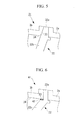
Fig. 4} Fig. 4 is an enlarged view of relevant portions of a turbine according to a second embodiment of the present invention. - {
Fig. 5} Fig. 5 is an enlarged view of relevant portions of a turbine according to a third embodiment of the present invention. - {
Fig. 6} Fig. 6 is an enlarged view of relevant portions of a turbine according to a fourth embodiment of the present invention. - {
Fig. 7} Fig. 7 is a perspective sectional view of relevant portions of a turbine according to a fifth embodiment of the present invention. - A first embodiment of a turbine according to the present invention will be described below with reference to
Figs. 1 to 3 .
Fig. 1 shows a lateral sectional view of a turbine according to the first embodiment of the present invention;Fig. 2 is a perspective sectional view of relevant portions of the turbine shown inFig. 1 ; andFig. 3 is a longitudinal sectional view of relevant portions of a support portion shown inFig. 1 . - A
turbine 1 obtains a rotational force using, for example, high-temperature steam from a boiler (not shown); using this rotational force, drives a generator connected via a rotation shaft; and, as shown inFig. 1 , is configured to include aturbine rotor 2 and acasing 3 as main components. - Individual end portions of the
turbine rotor 2 are supported on support bases (frame) via bearings (journal bearings) in a rotatable manner, and a plurality of turbine blades (rotor blades) are attached to individual outer circumferential portions of theturbine rotor 2 along the circumferential direction. - The
casing 3 is a vertically divided casing that is divided into two portions in a front-back direction (left-right direction inFig.1 ) and is provided with afront casing 3a located on the right side inFig. 1 and arear casing 3b located on the left side inFig. 1 . In addition,flange portions 9a of asupport portion 9 that supports a stator-blade holding ring 8 are configured so as to be sandwiched between thefront casing 3a and therear casing 3b.
The stator-blade holding ring 8 is disposed so as to surround theturbine rotor 2 and the turbine blades on the radially outer side, and, at its inner circumferential portion, a plurality of turbine nozzles (stator blades) are attached along the circumferential direction. - As shown in
Figs. 1 and2 , thesupport portion 9 includes theflange portions 9a, circular-truncatedcone portions 9b, andthick plate portions 9c.
Theflange portions 9a are plate-like members that are ring-like (doughnut-like) in plan view, having a fixed thickness and a fixed length (width) over the circumferential direction, and are secured, via a plurality of bolts (fastening members), between a joining surface of thefront casing 3a (seeFig. 1 ) and a joining surface of therear casing 3b (seeFig. 1 ) in an attachable/detachable manner.
The circular-truncatedcone portions 9b are mortar-like members that have a fixed thickness and a fixed length (width) over the circumferential direction; that protrude backward (from afront casing 3a side toward arear casing 3b side); that connect theflange portions 9a and the stator-blade holdingring 8 at upper-half portions thereof; and that connect thethick plate portions 9c and the stator-blade holdingring 8 at lower-half portions thereof.
As shown inFig. 3 , thethick plate portions 9c are plate-like members that are crescent-like in plan view and that are formed so that the plate thickness thereof is greater than the plate thickness of theflange portions 9a and the circular-truncatedcone portions 9b.
Note that the "plate thickness" of thethick plate portions 9c refers to a thickness in a direction parallel to a direction in which a turbine axis (axis in the longitudinal direction: rotational axis) of the turbine 1 (seeFig. 1 ) extends, which is indicated by a reference sign C inFig. 2 ; in other words, it refers to a thickness in the left-right direction inFig. 1 . - With the
turbine 1 according to this embodiment, thethick plate portions 9c provided (formed) in thesupport portion 9 increase (enhance) the rigidity of thesupport portion 9 as a whole; therefore, it is possible to prevent deforming (tilting) of the support portion 9 (more specifically, the circular-truncatedcone portions 9b) caused by a difference (pressure difference) between pressure that acts on a high-pressure side (right side inFig. 1 ) surface of the support portion 9 (more specifically, the circular-truncatedconed portions 9b) and pressure that acts on a low-pressure side (left side inFig. 1 ) surface of the support portion 9 (more specifically, the circular-truncatedcone portions 9b).
In addition, with thethick plate portions 9c provided (formed) in thesupport portion 9, it is possible to prevent an asymmetrical differential thermal expansion of the support portion 9 (more specifically, the circular-truncatedcone portions 9b) caused by having a high-temperature working fluid (for example, combustion gas or steam) pass through the inside of the stator-blade holding ring 8, as well as deforming (tilting) of the support portion 9 (more specifically, the circular-truncatedcone portions 9b) caused by this asymmetrical differential thermal expansion.
Furthermore, because deforming of thesupport portion 9 can be prevented, a tip clearance between tips (distal ends) of the turbine blades and an inner circumferential surface of the stator-blade holding ring 8 can be held constant, thereby making it possible to reduce leakage (tip leakage) from the tips of the turbine blades; and thus, turbine efficiency (performance) can be enhanced and contact between the tips of the turbine blades and the inner circumferential surface of the stator-blade holding ring 8 can also be prevented, making it possible to prevent damage to and breakage of the turbine blades and the turbine nozzles. Accordingly, the reliability of theturbine 1 can be enhanced. - A second embodiment of the turbine according to the present invention will be described with reference to
Fig. 4 .
Fig. 4 is an enlarged view of relevant portions of a turbine according to this embodiment.
Aturbine 21 according to this embodiment differs from the above-described first embodiment in that asupport portion 22 is provided instead of thesupport portion 9. Because other constituent components are the same as those in the above-described first embodiment, descriptions of those constituent components will be omitted. - The
support portion 22 according to this embodiment is provided withflange portions 22a and circular-truncated cone portions 22b.
Theflange portions 22a are plate-like members that are ring-like (doughnut-like) in plan view, having a fixed thickness and a fixed length (width) over the circumferential direction, and are secured, via a plurality of bolts (fastening members), between the joining surface of thefront casing 3a and the joining surface of therear casing 3b in an attachable/detachable manner.
The circular-truncated cone portions 22b are mortar-like members that have a fixed thickness over the circumferential direction; that protrude backward (from thefront casing 3a side toward therear casing 3b side); and that connect theflange portions 22a and the stator-blade holding ring 8 in the circumferential direction. - In addition, outer circumferential surfaces (circumferential surfaces at the radially outer side) 23 of the circular-
truncated cone portions 22b are provided (formed) so as to be located in the vicinity of innercircumferential surfaces 24 of thefront casing 3a and therear casing 3b, that is, so as to be located as close as possible to the innercircumferential surfaces 24 of thefront casing 3a and therear casing 3b.
Thus, just a slight deforming (tilting) of the support portion 22 (more specifically, the circular-truncated cone portions 22b) caused by a pressure difference or differential thermal expansion brings the outercircumferential surfaces 23 of the circular-truncated cone portions 22b into contact with the innercircumferential surfaces 24 of thefront casing 3a, thereby preventing any further deforming (tilting) of the support portion 22 (more specifically, the circular-truncated cone portions 22b). - With the
turbine 21 according to this embodiment, deforming (tilting) of the support portion 22 (more specifically, the circular-truncated cone portions 22b) caused by a pressure difference or differential thermal expansion can be suppressed to the minimum (significantly reduced); therefore, the tip clearance between the tips (distal ends) of the turbine blades and the stator-blade holding ring 8 can be held substantially constant, thereby making it possible to reduce the leakage (tip leakage) from the tips of the turbine blades; and thus, the turbine efficiency (performance) can be enhanced and contact between the tips of the turbine blades and the inner circumferential surface of the stator-blade hooding ring 8 can also be prevented, making it possible to prevent damage to and breakage of the turbine blades and the turbine nozzles. Accordingly, the reliability of theturbine 21 can be enhanced. - A third embodiment of the turbine according to the present invention will be described with reference to
Fig. 5 .
Fig. 5 is an enlarged view of relevant portions of a turbine according to this embodiment.
Aturbine 31 according to this embodiment differs from the above-described first embodiment in that asupport portion 32 is provided instead of thesupport portion 9. Because other constituent components are the same as those in the above-described first embodiment, descriptions of those constituent components will be omitted. - The
support portion 32 according to this embodiment is provided withflange portions 32a and circular-truncated cone portions 32b.
Theflange portions 32a are plate-like members that are ring-like (doughnut-like) in plan view and that are formed so as to gradually increase in thickness from a radially outer side toward a radially inner side as well as to have a fixed length (width) in the circumferential direction, and are secured, via a plurality of bolts (fastening members), between the joining surface of thefront casing 3a and the joining surface of therear casing 3b in an attachable/detachable manner. Note that, as shown inFig. 5 , the joiningsurfaces 33 of thefront casing 3a in this embodiment are provided (formed) so as to coincide with (come in contact with) joiningsurfaces 34 of theflange portions 32a.
The circular-truncated cone portions 32b are mortar-like members that have a fixed thickness over the circumferential direction; that protrude backward (from thefront casing 3a side toward therear casing 3b side); and that connect theflange portions 32a and the stator-blade holding ring 8. - With the
turbine 31 according to this embodiment, theflange portions 32a provided (formed) in thesupport portion 32 increase (enhance) the rigidity of thesupport portion 32 as a whole; therefore, it is possible to prevent deforming (tilting) of the support portion 32 (more specifically, the circular-truncated cone portions 32b) caused by a difference (pressure difference) between pressure that acts on a high-pressure side (right side inFig. 5 ) surface of the support portion 32 (more specifically, the circular-truncatedconed portions 32b) and pressure that acts on a low-pressure side (left side inFig. 5 ) surface of the support portion 32 (more specifically, the circular-truncated cone portions 32b).
In addition, with theflange portions 32a provided (formed) in thesupport portion 32, it is possible to prevent asymmetrical differential thermal expansion of the support portion 32 (more specifically, the circular-truncated cone portions 32b) caused by having a high-temperature working fluid (for example, combustion gas or steam) pass through the inside of the stator-blade holding ring 8, as well as deforming (tilting) of the support portion 32 (more specifically, the circular-truncated cone portions 32b) caused by this asymmetrical differential thermal expansion.
Furthermore, because deforming of thesupport portion 32 can be prevented, the tip clearance between the tips (distal ends) of the turbine blades and the inner circumferential surface of the stator-blade holding ring 8 can be held constant, thereby making it possible to reduce leakage (tip leakage) from the tips of the turbine blades; and thus, the turbine efficiency (performance) can be enhanced, and contact between the tips of the turbine blades and the inner circumferential surface of the stator-blade holding ring 8 can also be prevented, making it possible to prevent damage to and breakage of the turbine blades and the turbine nozzles. Accordingly, the reliability of theturbine 31 can be enhanced. - In addition, in the
turbine 31 according to this embodiment, the joiningsurfaces 33 of thefront casing 3a and the joiningsurfaces 34 of theflange portions 32a are individually formed as tapered surfaces (formed like a circular truncated cone); therefore, when assembling thecasing 3, coupling alignment (centering) between thefront casing 3a and thesupport portion 32 can be easily performed, thereby making it possible to shorten the processing time required for assembling thecasing 3. - A fourth embodiment of the turbine according to the present invention will be described with reference to
Fig. 6 .
Fig. 6 is an enlarged view of relevant portions of a turbine according to this embodiment.
Aturbine 41 according to this embodiment differs from the above-described second embodiment in that aring 42 is provided between the outercircumferential surfaces 23 of the circular-truncated cone portions 22b and the innercircumferential surfaces 24 of thefront casing 3a. Because other constituent components are the same as those in the above-described second embodiment, descriptions of those constituent components will be omitted. - The
ring 42 is a thin plate-like member that is ring-like (doughnut-like) in plan view, having a fixed thickness and a fixed length (width) over the circumferential direction, and is fabricated using a high-thermal-expansion material (for example, SUS304) as a constituent. Note that thecasing 3 and thesupport portion 22 are fabricated using, as constituents, metal materials (for example, alloys containing 2Cr) having lower thermal expansion rates than thering 42.
In other words, due to a high-temperature working fluid (for example, combustion gas or steam) passing through the inside of the stator-blade holding ring 8, thering 42 expands at a greater thermal expansion rate than thecasing 3 and thesupport portion 22, thereby causing the outercircumferential surfaces 23 of the circular-truncated cone portions 22b and an inner circumferential surface (circumferential surface on radially inner side) of thering 42 to come into close contact with each other, which also causes the innercircumferential surfaces 24 of thefront casing 3a and an outer circumferential surface (circumferential surface on radially outer side) of thering 42 to come into close contact with each other; therefore, a space formed between the outercircumferential surfaces 23 of the circular-truncated cone portions 22b and the innercircumferential surfaces 24 of thefront casing 3a is completely filled with thering 42, without any gap.
Accordingly, despite the tendency of the support portion 22 (more specifically, the circular-truncated cone portions 22b) to deform (tilt) due to a pressure difference or differential thermal expansion during turbine operation, deforming (tilting) of the support portion 22 (more specifically, the circular-truncated cone portions 22b) is prevented by thering 42 disposed (interposed) between the outercircumferential surfaces 23 of the circular-truncated cone portions 22b and the innercircumferential surfaces 24 of thefront casing 3a. - With the
turbine 42 according to this embodiment, because deforming (tilting) of the support portion 22 (more specifically, the circular-truncated cone portions 22b) due to a pressure difference or differential thermal expansion can be prevented, the tip clearance between the tips (distal ends) of the turbine blades and the inner circumferential surface of the stator-blade holding ring 8 can be held constant, thereby making it possible to reduce leakage (tip leakage) from the tips of the turbine blades; and thus, the turbine efficiency (performance) can be enhanced, and contact between the tips of the turbine blades and the inner circumferential surface of the stator-blade holding ring 8 can also be prevented, making it possible to prevent damage to and breakage of the turbine blades and the turbine nozzles. Accordingly, the reliability of theturbine 41 can be enhanced. - A fifth embodiment of the turbine according to the present invention will be described with reference to
Fig. 7 .
Fig. 7 is a perspective sectional view of relevant portions of a turbine according to this embodiment.
Aturbine 51 according to this embodiment differs from the above-described first embodiment in that asupport portion 52 is provided instead of thesupport portion 9. Because other constituent components are the same as those in the above-described first embodiment, descriptions of those constituent components will be omitted. - The
support portion 52 according to this embodiment is provided withflange portions 52a and circular-truncated cone portions 52b.
Theflange portions 52a are plate-like members that are ring-like (doughnut-like) in plan view, having a fixed thickness and a fixed length (width) over the circumferential direction, and are secured, via a plurality of bolts (fastening members), between the joining surface of thefront casing 3a (seeFig. 1 ) and the joining surface of therear casing 3b (seeFig. 1 ) in an attachable/detachable manner.
The circular-truncated cone portions 52b are mortar-like members that have a fixed thickness and a fixed length (width) over the circumferential direction; that protrude backward (from thefront casing 3a side toward therear casing 3b side); and that connect theflange portions 52a and the stator-blade holding ring 8. - With the
turbine 51 according to this embodiment, because the circular-truncated cone portions 52b are provided (formed) so as to have a fixed length (width) over the circumferential direction, it is possible to prevent asymmetrical differential thermal expansion of the support portion 52 (more specifically, the circular-truncated cone portions 52b), as well as deforming (tilting) of the support portion 52 (more specifically, the circular-truncated cone portions 52b) that are caused by a difference (pressure difference) between pressure that acts on a high-pressure side (right side inFig. 7 ) surface of the support portion 52 (more specifically, the circular-truncated cone portions 52b) and pressure that acts on a low-pressure side (left side inFig. 7 ) surface of the support portion 52 (more specifically, the circular-truncated cone portions 52b) and by having a high-temperature working fluid (for example, combustion gas or steam) pass through the inside of the stator-blade holding ring 8.
Furthermore, because deforming of thesupport portion 52 can be prevented, the tip clearance between tips (distal ends) of the turbine blades and the inner circumferential surface of the stator-blade holding ring 8 can be held constant, thereby making it possible to reduce leakage (tip leakage) from the tips of the turbine blades; and thus, the turbine efficiency (performance) can be enhanced, and contact between the tips of the turbine blades and the inner circumferential surface of the stator-blade holding ring 8 can also be prevented, making it possible to prevent damage to and breakage of the turbine blades and the turbine nozzles. Accordingly, the reliability of theturbine 51 can be enhanced. - Note that, in each embodiment described above, it is more preferable that the circular-truncated cone portions located at the lower-half portions have a greater plate thickness than the plate thickness of the circular-truncated cone portions located at the upper-half portion.
By doing so, the rigidity of the support portion can be further enhanced; the tip clearance between the tips (distal ends) of the turbine blades and the inner circumferential surface of the stator-blade holding ring can be held constant, thereby making it possible to further reduce leakage (tip leakage) from the tips of the turbine blades; and thus, turbine efficiency (performance) can be further enhanced, and contact between the tips of the turbine blades and the inner circumferential surface of the stator-blade holding ring can also be prevented, making it possible to prevent damage to and breakage of the turbine blades and the turbine nozzles. Accordingly, the reliability of the turbine can be further enhanced. -
- 1 turbine
- 2 turbine rotor
- 3 casing
- 3a front casing
- 3b rear casing
- 8 stator-blade holding ring
- 9 support portion
- 9a flange portion
- 9b circular-truncated cone portion
- 9c thick plate portion
- 22 support portion
- 22a flange portion
- 22b circular-truncated cone portion
- 23 outer circumferential surface
- 24 inner circumferential surface
- 31 turbine
- 32 support portion
- 32a flange portion
- 32b circular-truncated cone portion
- 33 joining surface
- 34 joining surface
- 41 turbine
- 42 ring
- 51 turbine
- 52 support portion
- 52a flange portion
- 52b circular-truncated cone portion
Claims (5)
- A turbine comprising:a vertically divided casing that is divided into two portions in a longitudinal direction; and a support portion that supports a stator-blade holding ring disposed in the casing,wherein, the support portion is provided with a flange portion that is secured between a joining surface of one portion of the casing and a joining surface of the other portion of the casing, being sandwiched therebetween, and a circular-truncated cone portion that connects the flange portion and the stator-blade holding ring, andwherein a thick plate portion having a greater plate thickness than the plate thickness of the flange portion and the stator-blade holding ring is provided between the flange portion located at a lower-half portion and the stator-blade holding ring.
- A turbine comprising:a vertically divided casing that is divided into two portions in a longitudinal direction; and a support portion that supports a stator-blade holding ring disposed in the casing,wherein, the support portion is provided with a flange portion that is secured between a joining surface of one portion of the casing and a joining surface of the other portion of the casing, being sandwiched therebetween, and a circular-truncated cone portion that connects the flange portion and the stator-blade holding ring, andwherein the flange portion is formed so that the plate thickness thereof gradually increases from a radially outer side toward a radially inner side thereof, and so that the joining surfaces of the casing coincide with the joining surfaces of the flange portion.
- A turbine comprising:a vertically divided casing that is divided into two portions in a longitudinal direction; and a support portion that supports a stator-blade holding ring disposed in the casing,wherein, the support portion is provided with a flange portion that is secured between a joining surface of one portion of the casing and a joining surface of the other portion of the casing, being sandwiched therebetween, and a circular-truncated cone portion that connects the flange portion and the stator-blade holding ring, andwherein a ring fabricated using a high thermal expansion material as a constituent is provided between an outer circumferential surface of the circular-truncated cone portion and an inner circumferential surface of the front casing.
- A turbine comprising:a vertically divided casing that is divided into two portions in a longitudinal direction; and a support portion that supports a stator-blade holding ring disposed in the casing,wherein, the support portion is provided with a flange portion that is secured between a joining surface of one portion of the casing and a joining surface of the other portion of the casing, being sandwiched therebetween, and a circular-truncated cone portion that connects the flange portion and the stator-blade holding ring, andwherein the circular-truncated cone portion is formed so as to have a fixed length in a circumferential direction.
- A turbine according to Claims 1 to 4, wherein the plate thickness at a lower-half portion of the circular-truncated portion is greater than the plate thickness at an upper-half portion of the circular-truncated portion.
Applications Claiming Priority (2)
| Application Number | Priority Date | Filing Date | Title |
|---|---|---|---|
| JP2009019797A JP2010174795A (en) | 2009-01-30 | 2009-01-30 | Turbine |
| PCT/JP2009/064108 WO2010087044A1 (en) | 2009-01-30 | 2009-08-10 | Turbine |
Publications (2)
| Publication Number | Publication Date |
|---|---|
| EP2385222A1 true EP2385222A1 (en) | 2011-11-09 |
| EP2385222A4 EP2385222A4 (en) | 2012-07-11 |
Family
ID=42395312
Family Applications (1)
| Application Number | Title | Priority Date | Filing Date |
|---|---|---|---|
| EP09839233A Withdrawn EP2385222A4 (en) | 2009-01-30 | 2009-08-10 | Turbine |
Country Status (6)
| Country | Link |
|---|---|
| US (1) | US20110176918A1 (en) |
| EP (1) | EP2385222A4 (en) |
| JP (1) | JP2010174795A (en) |
| CN (1) | CN102165143A (en) |
| WO (1) | WO2010087044A1 (en) |
| ZA (1) | ZA201101813B (en) |
Families Citing this family (6)
| Publication number | Priority date | Publication date | Assignee | Title |
|---|---|---|---|---|
| GB201105103D0 (en) * | 2011-03-28 | 2011-05-11 | Rolls Royce Plc | Securing system |
| US20170241435A1 (en) * | 2016-02-23 | 2017-08-24 | United Technologies Corporation | Systems and methods for stiffening cases on gas-turbine engines |
| CN106425283A (en) * | 2016-11-30 | 2017-02-22 | 哈尔滨理工大学 | Turbine rotor rotation work platform |
| DE102017203210A1 (en) * | 2017-02-28 | 2018-08-30 | Siemens Aktiengesellschaft | Turbine housing and method for assembling a turbine housing |
| CN114542212A (en) * | 2022-03-09 | 2022-05-27 | 中国船舶重工集团公司第七0三研究所 | Novel marine steam turbine cylinder of backing a car |
| WO2025108582A1 (en) * | 2023-11-24 | 2025-05-30 | Nuovo Pignone Tecnologie - S.R.L. | Turbomachine including stationary blades having a single hook |
Family Cites Families (11)
| Publication number | Priority date | Publication date | Assignee | Title |
|---|---|---|---|---|
| GB764501A (en) * | 1953-07-10 | 1956-12-28 | Licentia Gmbh | A high-pressure steam or gas turbine |
| JPS5227282B2 (en) * | 1970-11-05 | 1977-07-19 | ||
| GB1335939A (en) * | 1972-03-06 | 1973-10-31 | Kraftwerk Union Ag | Fluid flow machine |
| US3937589A (en) * | 1973-05-23 | 1976-02-10 | Kraftwerkunion Ag | High pressure double flow turbine construction |
| GB2226365B (en) * | 1988-12-22 | 1993-03-10 | Rolls Royce Plc | Turbomachine clearance control |
| JPH05195718A (en) * | 1992-01-23 | 1993-08-03 | Fuji Electric Co Ltd | Vessel-type turbine casing vertical temperature difference prevention device |
| JPH09133026A (en) * | 1995-11-13 | 1997-05-20 | Hitachi Ltd | Gas turbine and its casing |
| CZ326498A3 (en) * | 1996-04-11 | 1999-02-17 | Siemens Aktiengesellschaft | Method of equalizing feed in a turbo-machine and the turbo-machine per se |
| DE19700899A1 (en) * | 1997-01-14 | 1998-07-23 | Siemens Ag | Steam turbine |
| DE60121968T2 (en) * | 2001-11-22 | 2006-12-07 | Siemens Ag | Process for the manufacture of steam turbines |
| FR2913050B1 (en) * | 2007-02-28 | 2011-06-17 | Snecma | HIGH-PRESSURE TURBINE OF A TURBOMACHINE |
-
2009
- 2009-01-30 JP JP2009019797A patent/JP2010174795A/en not_active Withdrawn
- 2009-08-10 WO PCT/JP2009/064108 patent/WO2010087044A1/en not_active Ceased
- 2009-08-10 CN CN200980138447.2A patent/CN102165143A/en active Pending
- 2009-08-10 US US13/063,972 patent/US20110176918A1/en not_active Abandoned
- 2009-08-10 EP EP09839233A patent/EP2385222A4/en not_active Withdrawn
-
2011
- 2011-03-09 ZA ZA2011/01813A patent/ZA201101813B/en unknown
Also Published As
| Publication number | Publication date |
|---|---|
| WO2010087044A1 (en) | 2010-08-05 |
| JP2010174795A (en) | 2010-08-12 |
| US20110176918A1 (en) | 2011-07-21 |
| CN102165143A (en) | 2011-08-24 |
| EP2385222A4 (en) | 2012-07-11 |
| ZA201101813B (en) | 2012-10-31 |
Similar Documents
| Publication | Publication Date | Title |
|---|---|---|
| US20110176918A1 (en) | Turbine | |
| JP4476116B2 (en) | gas turbine | |
| KR101560110B1 (en) | Shaft sealing device and rotating machine comprising same | |
| CN104736799B (en) | Turbine Nozzle Fixed Portion Structure and Turbine Using the Fixed Portion Structure | |
| US10174628B2 (en) | Axially divided inner ring for a turbomachine and guide vane ring | |
| CN106536867B (en) | Stator blade, gas turbine, the remodeling method for splitting ring, the remodeling method of stator blade and segmentation ring | |
| US9677669B2 (en) | Shaft seal device and rotary machine | |
| US20180340435A1 (en) | Seal arrangement for a turbomachine, method for manufacturing a seal arrangement and turbomachine | |
| US20120228830A1 (en) | Labyrinth seal and method for producing a labyrinth seal | |
| JP6615573B2 (en) | Thrust foil bearing | |
| JP2006523803A (en) | Cutting blade centrally located on turbine blade with shroud | |
| KR20110102908A (en) | Turbine wheel with system for supporting blades axially | |
| CN111801487B (en) | Assembly of a turbomachine | |
| KR101667517B1 (en) | Fluid seal structure of heat engine including steam turbine | |
| US9404373B2 (en) | Turbine-blade retaining structure and rotary machine having the same | |
| JP5931450B2 (en) | Shaft seal device and rotary machine equipped with the same | |
| EP3059454B1 (en) | Impeller, rotary machine, and impeller manufacturing method | |
| JP2005106056A (en) | Turboshaft engine with two members connected through intervened seal | |
| JP5094833B2 (en) | Tilting pad journal bearing device | |
| EP3173599B1 (en) | Variable nozzle mechanism and variable displacement turbocharger | |
| JP5699132B2 (en) | Aircraft turbo engine stator shell with mechanical blade load transfer slit | |
| JP2015086876A (en) | Methods and systems for securing turbine nozzles | |
| CN108350934A (en) | Foil bearing, manufacturing method thereof, and intermediate manufacture of foil bearing | |
| US10662796B2 (en) | Seal device for turbine, turbine, and thin plate for seal device | |
| EP3835552B1 (en) | Turbine stator of a steam turbine and corresponding steam turbine |
Legal Events
| Date | Code | Title | Description |
|---|---|---|---|
| PUAI | Public reference made under article 153(3) epc to a published international application that has entered the european phase |
Free format text: ORIGINAL CODE: 0009012 |
|
| 17P | Request for examination filed |
Effective date: 20110329 |
|
| AK | Designated contracting states |
Kind code of ref document: A1 Designated state(s): AT BE BG CH CY CZ DE DK EE ES FI FR GB GR HR HU IE IS IT LI LT LU LV MC MK MT NL NO PL PT RO SE SI SK SM TR |
|
| DAX | Request for extension of the european patent (deleted) | ||
| A4 | Supplementary search report drawn up and despatched |
Effective date: 20120608 |
|
| RIC1 | Information provided on ipc code assigned before grant |
Ipc: F01D 25/24 20060101ALI20120601BHEP Ipc: F01D 25/28 20060101AFI20120601BHEP Ipc: F01D 25/26 20060101ALI20120601BHEP Ipc: F01D 25/00 20060101ALI20120601BHEP Ipc: F01D 9/00 20060101ALI20120601BHEP |
|
| STAA | Information on the status of an ep patent application or granted ep patent |
Free format text: STATUS: THE APPLICATION HAS BEEN WITHDRAWN |
|
| 18W | Application withdrawn |
Effective date: 20140310 |