EP2384860B1 - Power tool housing - Google Patents
Power tool housing Download PDFInfo
- Publication number
- EP2384860B1 EP2384860B1 EP11176543.4A EP11176543A EP2384860B1 EP 2384860 B1 EP2384860 B1 EP 2384860B1 EP 11176543 A EP11176543 A EP 11176543A EP 2384860 B1 EP2384860 B1 EP 2384860B1
- Authority
- EP
- European Patent Office
- Prior art keywords
- housing
- power tool
- output shaft
- tool according
- bearing
- Prior art date
- Legal status (The legal status is an assumption and is not a legal conclusion. Google has not performed a legal analysis and makes no representation as to the accuracy of the status listed.)
- Active
Links
- 230000033001 locomotion Effects 0.000 claims description 23
- 210000000078 claw Anatomy 0.000 claims description 8
- 239000003566 sealing material Substances 0.000 claims description 2
- 230000008878 coupling Effects 0.000 claims 1
- 238000010168 coupling process Methods 0.000 claims 1
- 238000005859 coupling reaction Methods 0.000 claims 1
- 230000007246 mechanism Effects 0.000 description 18
- 238000010276 construction Methods 0.000 description 11
- 229910052751 metal Inorganic materials 0.000 description 9
- 239000002184 metal Substances 0.000 description 9
- 230000005540 biological transmission Effects 0.000 description 8
- 239000000463 material Substances 0.000 description 5
- 230000000694 effects Effects 0.000 description 4
- 230000013011 mating Effects 0.000 description 4
- 238000000034 method Methods 0.000 description 4
- 230000008439 repair process Effects 0.000 description 4
- 238000006073 displacement reaction Methods 0.000 description 3
- 238000010521 absorption reaction Methods 0.000 description 2
- 238000005520 cutting process Methods 0.000 description 2
- 238000005553 drilling Methods 0.000 description 2
- 239000010687 lubricating oil Substances 0.000 description 2
- 238000012423 maintenance Methods 0.000 description 2
- 238000012986 modification Methods 0.000 description 2
- 230000004048 modification Effects 0.000 description 2
- 239000003921 oil Substances 0.000 description 2
- 229920003002 synthetic resin Polymers 0.000 description 2
- 239000000057 synthetic resin Substances 0.000 description 2
- 229910000838 Al alloy Inorganic materials 0.000 description 1
- 229910000897 Babbitt (metal) Inorganic materials 0.000 description 1
- 230000009471 action Effects 0.000 description 1
- 229910052782 aluminium Inorganic materials 0.000 description 1
- XAGFODPZIPBFFR-UHFFFAOYSA-N aluminium Chemical compound [Al] XAGFODPZIPBFFR-UHFFFAOYSA-N 0.000 description 1
- 230000000881 depressing effect Effects 0.000 description 1
- 230000000994 depressogenic effect Effects 0.000 description 1
- 230000002349 favourable effect Effects 0.000 description 1
- 239000004519 grease Substances 0.000 description 1
- 230000020169 heat generation Effects 0.000 description 1
- 238000004519 manufacturing process Methods 0.000 description 1
- 238000003825 pressing Methods 0.000 description 1
- 230000000717 retained effect Effects 0.000 description 1
- 238000007789 sealing Methods 0.000 description 1
- 230000006641 stabilisation Effects 0.000 description 1
- 238000011105 stabilization Methods 0.000 description 1
- 239000013585 weight reducing agent Substances 0.000 description 1
Images


Classifications
-
- B—PERFORMING OPERATIONS; TRANSPORTING
- B25—HAND TOOLS; PORTABLE POWER-DRIVEN TOOLS; MANIPULATORS
- B25F—COMBINATION OR MULTI-PURPOSE TOOLS NOT OTHERWISE PROVIDED FOR; DETAILS OR COMPONENTS OF PORTABLE POWER-DRIVEN TOOLS NOT PARTICULARLY RELATED TO THE OPERATIONS PERFORMED AND NOT OTHERWISE PROVIDED FOR
- B25F5/00—Details or components of portable power-driven tools not particularly related to the operations performed and not otherwise provided for
- B25F5/02—Construction of casings, bodies or handles
-
- B—PERFORMING OPERATIONS; TRANSPORTING
- B25—HAND TOOLS; PORTABLE POWER-DRIVEN TOOLS; MANIPULATORS
- B25D—PERCUSSIVE TOOLS
- B25D17/00—Details of, or accessories for, portable power-driven percussive tools
- B25D17/04—Handles; Handle mountings
- B25D17/043—Handles resiliently mounted relative to the hammer housing
-
- B—PERFORMING OPERATIONS; TRANSPORTING
- B25—HAND TOOLS; PORTABLE POWER-DRIVEN TOOLS; MANIPULATORS
- B25F—COMBINATION OR MULTI-PURPOSE TOOLS NOT OTHERWISE PROVIDED FOR; DETAILS OR COMPONENTS OF PORTABLE POWER-DRIVEN TOOLS NOT PARTICULARLY RELATED TO THE OPERATIONS PERFORMED AND NOT OTHERWISE PROVIDED FOR
- B25F5/00—Details or components of portable power-driven tools not particularly related to the operations performed and not otherwise provided for
- B25F5/006—Vibration damping means
-
- B—PERFORMING OPERATIONS; TRANSPORTING
- B25—HAND TOOLS; PORTABLE POWER-DRIVEN TOOLS; MANIPULATORS
- B25D—PERCUSSIVE TOOLS
- B25D2211/00—Details of portable percussive tools with electromotor or other motor drive
- B25D2211/003—Crossed drill and motor spindles
-
- B—PERFORMING OPERATIONS; TRANSPORTING
- B25—HAND TOOLS; PORTABLE POWER-DRIVEN TOOLS; MANIPULATORS
- B25D—PERCUSSIVE TOOLS
- B25D2211/00—Details of portable percussive tools with electromotor or other motor drive
- B25D2211/06—Means for driving the impulse member
- B25D2211/061—Swash-plate actuated impulse-driving mechanisms
-
- B—PERFORMING OPERATIONS; TRANSPORTING
- B25—HAND TOOLS; PORTABLE POWER-DRIVEN TOOLS; MANIPULATORS
- B25D—PERCUSSIVE TOOLS
- B25D2250/00—General details of portable percussive tools; Components used in portable percussive tools
- B25D2250/121—Housing details
Definitions
- the present invention relates to a structure of a housing of a hand-held power tool according to the preamble of claim 1.
- the object can be achieved by a power tool according to claim 1.
- the handle is elastically connected to the power tool body such that it can slide with respect to the power tool body in the axial direction of the tool bit. Therefore, the elastic element can absorb vibration by linear deformation in the axial direction of the tool bit, so that the vibration absorption efficiency of the elastic element can be enhanced. Further, with the construction in which the handle linearly moves with respect to the power tool body, unlike the known rotary handle, the vertical length of the handle is not restricted, so that the size of the handle can be reduced. Further, in this invention, with the construction in which the power tool body has an extending region that extends to a lower region of the handle and receives the sliding movement of the handle, the handle can be supported with stability.
- the handle includes a grip part that extends in a vertical direction transverse to the axial direction of the tool bit, upper and lower arms that extend from extending ends of the grip part in the axial direction of the tool bit, and a transverse part that connects extending ends of the upper and lower arms, so that the handle is configured as a closed-loop frame structure.
- the rigidity of the handle can be increased. Therefore, this structure is effective in preventing damage to the handle in the event of drop of the power tool.
- a side surface region of the handle which is parallel to the axial direction of the tool bit has a sliding surface that can slide with respect to the power tool body.
- the "side surface region of the handle” in this invention represents side surface regions of the arms and the transverse part.
- the sliding surface includes a first sliding region extending in the axial direction of the tool bit, and a second sliding region extending in a vertical direction transverse to the extending direction of the first sliding region.
- the first sliding region is provided on the side surfaces of the arms and the second sliding region is provided on the side surface of the transverse part.
- the hand-held power tool further includes an electric motor that drives the tool bit, and a battery pack from which the electric motor is powered.
- the extending region extending to the lower region of the handle forms a battery pack mounting part to which the battery pack is detachably mounted.
- the extending region extending from the power tool body can be rationally used as a sliding guide region for the handle and as a mount for the battery pack.
- the power tool body and the handle are connected to each other via a guide, and at upper and lower end portions of the handle, the guide allows the handle to slide with respect to the power tool body in the axial direction of the tool bit, while preventing the handle from moving with respect to the power tool body in any direction except the axial direction of the tool bit.
- rattling of the handle can be reduced in the vertical direction as well as in the lateral direction, so that rattling can be further reduced.
- the guide includes a concave groove extending in the axial direction of the tool bit and a projection that is engaged with the concave groove for relative movement, and the projection comprises a metal pin.
- the concave groove is formed of a different material from the metal pin.
- one of the concave groove and the projection is formed on the power tool body side and the other is formed on the handle side.
- at least the side on which the groove is formed may be made of synthetic resin or aluminum alloy.
- the protrusion and the groove which slide with respect to each other are formed of heterogeneous materials so that the sliding ability can be improved.
- FIG. 1 shows an entire structure of the hammer drill 101 according to this example
- FIG. 2 is a side view showing an internal structure of the hammer drill 101 by broken line and partly in section. As shown in FIG.
- the hammer drill 101 mainly includes a body 103 that forms an outer shell of the hammer drill 101, a hammer bit 119 detachably coupled to the tip end region of the body 103 via a tool holder 137, a handgrip 109 connected to the body 103 on the side opposite to the hammer bit 119 and designed to be held by a user, and a battery pack 107 attached to the underside of the body 103.
- the body 103, the hammer bit 119 and the handgrip 109 are features that correspond to the "power tool body", the "tool bit” and the "handle", respectively.
- the hammer bit 119 is held by the tool holder 137 such that it is allowed to reciprocate with respect to the tool holder in its axial direction and prevented from rotating with respect to the tool holder in its circumferential direction.
- the side of the hammer bit 119 is taken as the front side and the side of the handgrip 109 as the rear side.
- the body 103 mainly includes a housing 105 that houses an electric motor 111, a motion converting mechanism 113, a striking mechanism 115 and a power transmitting mechanism 117.
- the rotating output of the electric motor 111 is appropriately converted into linear motion via the motion converting mechanism 113 and transmitted to the striking mechanism 115.
- an impact force is generated in the axial direction of the hammer bit 119 via the striking mechanism 115.
- the power transmitting mechanism 117 appropriately reduces the speed of the rotating output of the electric motor 111 and then transmits the rotating output to the hammer bit 119.
- the hammer bit 119 is caused to rotate in the circumferential direction.
- the electric motor 111 is driven when an electric switch 109b is turned on by depressing a trigger 109a on the handgrip 109.
- the electric motor 111 is disposed in a lower region within the housing 105 and arranged such that its axis of rotation extends obliquely with respect to the vertical direction and transversely to the axial direction of the hammer bit 119.
- the motion converting mechanism 113 mainly includes a driving gear 121 that is rotated by the electric motor 111, a driven gear 123 that engages with the driving gear 121 and is rotated in a vertical plane, a rotating element 127 that rotates together with the driven gear 123 via an intermediate shaft 125, a swinging member in the form of a swinging ring 129 that is caused to swing in the axial direction of the hammer bit 119 by rotation of the rotating element 127, and a driving element in the form of a cylindrical piston 141 that is caused to reciprocate by swinging movement of the swinging ring 129.
- the swinging ring 129 is rotatably supported on the rotating element 127 via a bearing.
- the cylindrical piston 141 has a closed end (closed rear end).
- the cylindrical piston 141 is slidably disposed within the cylindrical tool holder 137 that is disposed coaxially with the cylindrical piston 141.
- the cylindrical piston 141 is driven by swinging movement (by its components in the axial direction of the hammer bit 119) of the swinging ring 129, and reciprocates along the tool holder 137.
- the striking element 115 mainly includes a striking element in the form of a striker 143 slidably disposed within the bore of the cylindrical piston 141, and an intermediate element in the form of an impact bolt 145 that is slidably disposed within the tool holder 137 and serves to transmit the kinetic energy of the striker 143 to the hammer bit 119.
- the striker 143 is then driven (linearly moved) by pressure fluctuations of air (the action of an air spring) within an air chamber of the cylindrical piston 141 as a result of the sliding movement of the piston 141.
- the striker 143 then collides with (strikes) the impact bolt 145 which is slidably disposed within the tool holder 137, and transmits the striking force to the hammer bit 119 via the impact bolt 145.
- the cylindrical piston 141, the striker 143 and the impact bolt 145 form a bit striking mechanism.
- the power transmitting mechanism 117 mainly includes a first transmission gear 131 that is caused to rotate in a vertical plane by the electric motor 111 via the intermediate shaft 125, and a second transmission gear 133 that is engaged with the first transmission gear 131 and coaxially mounted on the tool holder 137.
- the rotational driving force of the second transmission gear 133 is transmitted to the tool holder 137 and then to the hammer bit 119 held by the tool holder 137.
- the hammer bit 119 performs a drilling operation on a workpiece (concrete) by a hammering movement in the axial direction and a drilling movement in the circumferential direction.
- the hammer drill 101 can be appropriately switched between a hammering operation mode in which only a striking force in the axial direction is applied to the hammer bit 119, and a hammer drill operation mode in which a striking force in the axial direction and a rotating force in the circumferential direction are applied to the hammer bit 119.
- This construction is not directly related to this invention and therefore will not be described.
- FIGS. 3 and 4 show the vibration-proof structure of the handgrip 109
- FIGS. 5 and 6 are sectional views taken along line A-A and line B-B in FIG. 3 , respectively.
- the hollow housing 105 forming the body 103 includes right and left housing halves 105L, 105R into which the housing 105 is split in the axial direction of the hammer bit 119.
- FIGS. 3 and 4 show the state in which the housing half 105L on the left side of the hammer drill 101 as viewed from the front is removed.
- a plurality of cylindrical dowels 151 are integrally formed on its edge region on the mating face side (the inner surface side) and protrude in a direction perpendicular to the mating face.
- a plurality of dowel holes 153 are formed to correspond with the dowels 151.
- the dowels 151 are fitted in the dowel holes 153, and in this state, the right and left housing halves 105L, 105R are joined to each other by screws 155 through the dowels.
- the handgrip 109 includes a grip part 161 extending in a vertical direction transverse to the axial direction of the hammer bit 119, upper and lower arms 162, 163 extending from extending ends of the grip part in a horizontal direction transverse to the extending direction of the grip part, and a stay 164 that extends substantially parallel to the grip part 161 and connects the extending ends of the upper and lower arms 162, 163, so that the handgrip 109 is configured as a closed-loop integral frame structure.
- the stay 164 is a feature that corresponds to the "transverse part".
- the handgrip 109 includes right and left handgrip halves 109L, 109R into which the handgrip 109 is split in the axial direction of the hammer bit 119.
- a plurality of cylindrical dowels 167 are integrally formed on its edge region on the mating face side (the inner surface side) and protrude in a direction perpendicular to the mating face.
- a plurality of dowel holes 168 are formed to correspond with the dowels 167.
- the dowels 167 are fitted in the dowel holes 168, and in this state, the right and left handgrip halves 109L, 109R are joined to each other by screws 169 through the dowels.
- a rear region of the housing 105 is generally U-shaped in side view, having an upper extending portion 105a extending to the upper arm 162 of the handgrip 109, a lower extending portion 105b extending to the lower arm 163, and an intermediate portion 105c extending therebetween. Openings are formed in a lower surface and a rear end surface of the upper extending portion 105a, an upper surface of the lower extending portion 105b and a rear surface of the intermediate portion 105c.
- the upper and lower arms 162, 163 and the stay 164 of the handgrip 109 are inserted into the upper extending portion 105a, the lower extending portion 105b and the intermediate portion 105c, respectively, through the openings, and can move in the axial direction of the hammer bit 119.
- the lower extending portion 105b is a feature that corresponds to the "extending region”.
- the battery pack 107 is detachably mounted on the underside of the lower extending portion 105b of the housing 105. Specifically, the lower extending portion 105b also serves as a mount for the battery pack 107.
- the handgrip 109 is held (enclosed) by the generally U-shaped rear region of the housing 105 from laterally outward.
- the handgrip 109 is supported in such a manner as to be movable with respect to the housing 105 in the axial direction of the hammer bit 119.
- the handgrip 109 is connected at the front end to the housing 105 via upper and lower coil springs 181, 183.
- the upper coil spring 181 is elastically disposed between a front end surface of the upper arm 162 and a rear wall surface of an inner housing 185 disposed within the housing 105.
- the lower coil spring 183 is elastically disposed between a front lower portion of the stay 164 and the rear wall surface of the inner housing 185.
- the right and left side surfaces of the upper and lower arms 162, 163 and the right and left side surfaces of the stay 164 in the handgrip 109 have smooth surfaces 162a, 163a, 164a parallel to the axial direction of the hammer bit 119, in part or in entirety.
- the smooth surfaces 162a, 163a of the upper and lower arms 162, 163 extend in the axial direction of the hammer bit 119, and the smooth surface 164a of the stay 164 extends vertically in a direction transverse to the axial direction of the hammer bit 119.
- the smooth surfaces 162a, 163a, 164a are slidably held in contact with opening edges (wall surfaces) 165 (see FIG. 5 ) of the openings of the upper extending portion 105a, the lower extending portion 105b and the intermediate portion lost.
- the opening edges 165 form sliding guide surfaces which slide in surface contact with the smooth surfaces 162a, 163a, 164a.
- the structures of contact between the smooth surfaces 163a, 164a of the lower arm 163 and the stay 164 and the opening edges of the lower extending portion 105b and the intermediate portion 105c, which are not shown, are similarly configured as the structure of contact between the smooth surface 162a of the upper arm 162 and the opening edge 165 of the upper extending portion 105a, which is shown in FIG. 5 .
- the smooth surfaces 162a, 163a, 164a are features that correspond to the "sliding surface”.
- the smooth surfaces 162a, 163a of the upper extending portion 105a and the lower extending portion 105b and the smooth surface 164a of the stay 164 are features that correspond to the "first sliding region.” and the "second sliding region", respectively.
- Slide guides 171, 173, 175 are provided between the upper arm 162 of the handgrip 109 and the upper extending portion 105a of the housing 105, between the lower arm 163 and the lower extending portion 105b and between the stay 164 and the intermediate portion 105c.
- the upper and lower slide guides 171, 173 are features that correspond to the " guide”.
- the upper slide guide 171 includes a slot 171a that is formed generally in the middle of the upper arm 162 in its extending direction, and a protrusion 171b that is formed on the upper extending portion 105a and slidably inserted through the slot 171a.
- the above-described cylindrical dowel 151 formed on the left housing half 105L also serves as the protrusion 171b.
- two dowels 151 are disposed side by side in the axial direction of the hammer bit 119 in such a manner as to serve also as protrusions 171b.
- the slot 171a is formed through the upper arm in the lateral direction (see FIG. 5 ) and has a predetermined length extending in the axial direction of the hammer bit 119 (see FIGS. 3 and 4 ).
- the lower slide guide 173 includes protrusions in the form of two metal pins 173b mounted to a rear end portion (an area of connection with the grip part 161) of the lower arm 163, and concave grooves 173a (shown by two-dot chain line in FIGS. 3 and 4 ) formed in the inner surface of the upper rear-end portion of the lower extending portion 105b (in the inner surfaces of the right and left housing halves 105L, 105R).
- the ends of each of the metal pins 173b are slidably engaged in the concave grooves 173a.
- the two metal pins 173b extend through the lower arm 163 in the lateral direction and are disposed side by side with a predetermined spacing therebetween in the axial direction of the hammer bit 119.
- the extending ends (axial ends) of the metal pins 173b are engaged in the concave grooves 173a.
- the concave grooves 173a have a predetermined length extending in the axial direction of the hammer bit 119.
- the right and left housing halves 105L, 105R having the concave grooves 173a are formed of a different material from the metal pins 173b, for example, a light material such as synthetic resin and aluminum.
- the sliding structure formed of heterogeneous materials can obtain higher sliding ability.
- the intermediate slide guide 175 includes a concave groove 175a and a circular projection 175b (shown by two-dot chain line in the drawings).
- the concave groove 175a is formed in the side surface of the front lower portion of the stay 164 and has a predetermined length extending in the axial direction of the hammer bit 119.
- the circular projection 175b extends inward from the inner surface of the intermediate portion 105c of the housing 105 and is slidably engaged in the concave groove 175a.
- the handgrip 109 is prevented from moving in a vertical direction transverse to the axial direction of the hammer bit 119 with respect to the housing 105, and thus rattling of the handgrip 109 in the vertical direction is reduced.
- FIG. 3 shows an initial state of the handgrip 109 (the state in which the handgrip 109 is mounted to the housing 105). In this state, the handgrip 109 is biased rearward away from the housing 105 by the spring force of the coil springs 181, 183, and at least the protrusions 171b of the upper slide guide 171 are held in contact with the front end of the slot 171a.
- FIG. 4 shows the state in which the handgrip 109 is moved from the initial state to the housing 105 side (forward) as far as possible and the protrusions 171b come in contact with the rear end of the slot 171a (the state of maximum displacement). The maximum amount of relative movement (displacement) of the handgrip 109 is shown by L in FIG. 4 .
- An operation using the hammer drill 101 is performed while the user holds the grip part 161 of the handgrip 109 and applies a forward pressing force to the hammer drill 101.
- the operation is performed in the state in which the protrusions 171b, the metal pins 173b and the circular projection 175b of the upper, lower and intermediate slide guides 171, 173, 175 are placed between the rear and front ends of the slot 171a and the concave grooves 173a, 175a, respectively.
- the handgrip 109 is allowed to move with respect to the housing 105 in the axial direction of the hammer bit 119. Therefore, during operation, vibration which is caused in the housing 105 and transmitted from the housing 105 to the handgrip 109 can be reduced by the coil springs 181, 183.
- the handgrip 109 is elastically connected to the housing 105 by the upper and lower coil springs 181, 183 and mounted to the housing 105 for relative movement in the axial direction of the hammer bit 119. Therefore, the coil springs 181, 183 absorb vibration by linear deformation in the axial direction of the hammer bit, so that the vibration absorption efficiency of the coil springs 181, 183 can be enhanced.
- the vertical length of the handgrip 109 is not restricted, so that the size of the handgrip 109 can be reduced.
- the lower arm 163 of the handgrip 109 can be slidably supported with stability by the lower extending portion 105b of the housing 105, and in addition, the lower extending portion 105b also serves as a mount for the battery pack 107. Therefore, a rational supporting structure can be realized.
- a rear region of the housing 105 is generally U-shaped in side view, having the upper and lower extending portions 105a, 105b extending rearward and the intermediate portion 105c extending therebetween, and the upper and lower arms 162, 163 and the stay 164 of the handgrip 109 are inserted into this generally U-shaped region.
- the relatively wide smooth surfaces 162a, 163a, 164a can be formed on the right and left side surfaces of the arms 162, 163 and the stay 164, so that rattling of the handgrip 109 can be reduced in the lateral direction.
- the upper, lower and intermediate slide guides 171, 173, 175 rattling of the handgrip 109 can be reduced in the vertical direction.
- rattling of the handgrip 109 can be reduced in any direction except the axial direction of the hammer bit 119. Therefore, even if the spring constant of the coil springs 181, 183 is reduced, a sufficient vibration proofing effect can be obtained. Further, such a vibration-proof handgrip 109 feels comfortable to use.
- the hammer drill is described as a representative example , but the present invention can also be applied to a hammer in which the hammer bit 119 performs only the striking movement in the axial direction, or a cutting power tool, such as a reciprocating saw and a jig saw, which performs a cutting operation on a workpiece by reciprocating movement of a blade.
- a battery-powered power tool is described in which the electric motor 111 is powered from the battery pack 107, but the present invention can also be applied to a power tool in which the electric motor 111 is AC powered.
- FIG. 7 is a view showing an entire hammer drill 1 as a representative embodiment.
- a battery 2 is mounted on the underside of the rear (shown on the left in FIG. 7 ) of the hammer drill and a motor 3 is housed in front of the battery 2 such that an output shaft 4 is oriented upward.
- An output section is disposed above the motor 3.
- an intermediate shaft 6 is supported in the longitudinal direction, and a first gear 7 and a swash bearing 8 are fitted on the intermediate shaft 6 one behind the other such that they can individually rotate separately from the intermediate shaft 6.
- a clutch sleeve 9 is arranged between the first gear 7 and the swash bearing 8 such that it can rotate together with the intermediate shaft 6 and can slide in its axial direction.
- a cylindrical tool holder 10 is supported above the intermediate shaft 6 and in parallel therewith, and a second gear 11 that engages with the first gear 7 is integrally fitted on the tool holder 10.
- a piston cylinder 12 is loosely fitted in the tool holder 10 such that it can reciprocate, and a striker 13 is disposed within the piston cylinder 12.
- the rear end of the piston cylinder 12 is connected to an arm 14 of the swash bearing 8.
- an impact bolt 15 is housed within a front portion of the piston cylinder 12 such that it can move in the longitudinal direction.
- a housing of the hammer drill 1 has two parts, or a body housing 20 and a front housing 21.
- the body housing 20 covers all over a rear region of the hammer drill 1 which includes a rear part of the output section 5 and the motor 3, and the front housing 21 covers a front part of the output section 5 in front of the body housing 20. Further, the rear part of the output section 5 is housed within an inner housing 22 installed within the body housing 20.
- the body housing 20 is formed by housing halves in the form of a pair of right and left housings 23, 24.
- Cylindrical bosses 25 each having a threaded bore extend from an inner surface of the left housing 23, and cylindrical bosses 26 each having a through bore extend from an inner surface of the right housing 24.
- the bosses 26 are fitted on the bosses 25 in a coaxially butted manner. Therefore, the right and left housings 23, 24 are assembled into the body housing 20 by inserting screws 27 through each of the bosses 26 from the right housing 24 side and threadably into the associated bosses 25.
- a handle 28 is connected to an upper portion of the rear end of the body housing 20.
- the handle 28 houses a switch 16 which is actuated to drive the motor 3, and the handle 28 has a switch lever 17 which is depressed to turn on the switch 16.
- the inner housing 22 has a box-like shape having an open front end and a closed rear end.
- the inner housing 22 supports a rear end of the intermediate shaft 6 via a ball bearing 29 which is provided within the rear of the inner housing 22.
- an insert hole 30 is formed through the bottom of the inner housing 22, and the output shaft 4 of the motor 3 is inserted into the inner housing 22 through the insert hole 30 such that a ball bearing 31 mounted on the output shaft 4 is fitted in the insert hole 30.
- the inner housing 22 supports the output shaft 4.
- the motor 3 here is arranged within the body housing 20 in a tilted position in which the lower end of the output shaft 4 is located forward of the upper end of the output shaft 4.
- the upper end of the output shat 4 is inserted into the inner housing 22 through the insert hole 30 and engaged with a bevel gear 18, so that rotation of the output shaft 4 can be transmitted to the intermediate shaft 6.
- the bevel gear 18 is fixedly mounted on the rear end portion of the intermediate shaft 6 and located at an input end of the output section 5.
- a sleeve 32 is press-fitted onto the output shaft 4 on the upper end of the ball bearing 31 and a sealing material in the form of an oil seal 33 which is retained within the insert hole 30 is held in sliding contact with the sleeve 32, so that the inner housing 22 is sealed.
- a retaining ring 34 is engaged on the output shaft 4 on the upper end of the sleeve 32.
- a constricted part (groove) 35 is formed in the output shaft 4 at a position corresponding to the opening edge of the insert hole 30, and a stopper ring 36 is fitted in the constricted part 35. The stopper ring 36 is held in contact with an outer end surface of the ball bearing 31 fitted on the output shaft 4.
- a bearing retainer 37 is mounted on the opening edge of the insert hole 30 of the inner housing 22.
- the bearing retainer 37 has a semicircular arc shape to be arranged in contact with half of an circumferential portion of the outer end surface of the ball bearing 31.
- a pair of ring-shaped mounting parts 38 extend radially outward from both end portions (upper and lower portions in the vertical direction as viewed in FIGS. 8(B) and FIG. 8(C) ) of the bearing retainer 37.
- a nut 39 is fixedly mounted on each of the mounting parts 38, and a pair of engaging claws 40 are formed on the bearing retainer 37 between the mounting parts 38 and folded up away from the nut 39 into an L-shape.
- a pair of screw fastening parts 41 are formed on upper and lower portions (as viewed in FIGS. 8 (B) and FIG. 8 (C) ) of the inner housing 22.
- the screw fastening parts 41 each have a thickness large enough to be engaged and locked by the engaging claws 40 and each have a protrusion 42 on its end which faces an end of the other.
- the engaging claws 40 of the bearing retainer 37 When the engaging claws 40 of the bearing retainer 37 are engaged on the screw fastening parts 41, the engaging claws 40 come into contact with the protrusions 42 and thus lock the bearing retainer 37 against vertical movement (as viewed in FIGS. 8 (B) and FIG. 8 (C) ).
- the bearing retainer 37 is positioned in a mounting position in which the centers of the mounting part 38 and the nut 39 are aligned with a through hole (not shown) of the screw fastening part 41.
- a setscrew 43 is inserted through the screw fastening part 41 and the mounting part 38 and screwed into the nut 39.
- the bearing retainer 37 is fastened in contact with the opening edge of the insert hole 30 and the outer end surface of the ball bearing 31, and thus, at the opening edge of the insert hole 30, it prevents the ball bearing 31 from slipping out.
- the sleeve 32 abuts against the ball bearing 31 mounted on the output shaft 4, from above or from the upper end of the output shaft 4, while the bearing retainer 37 also abuts against the ball bearing 31 from below or from the opposite side, so that the output shaft 4 is positioned without rattling in its axial direction.
- cylindrical portions 44 are formed on upper and lower portions of the rear end of the inner housing 22 and each have a positioning hole 45 through which the associated boss 25 of the left housing 23 is inserted in the assembled state of the body housing 20.
- an end surface of the cylindrical portion 44 is held in contact with a rib 46 which extends from the outer periphery of the boss 25 to an inner surface of the left housing 23.
- the right housing 24 is connected to the left housing 23.
- the boss 26 of the right housing 24 comes into contact with the end surface of the cylindrical portion 44, so that the cylindrical portion 44 is centrally positioned in the lateral direction. Specifically, assembling of the body housing 20 by the screws and fixed positioning of the inner housing 22 by the bosses 25, 26 can be simultaneously attained.
- the front end of the inner housing 22 or a protruding part 47 protrudes forward of the front open end of the body housing 20, and an O-ring 49 is fitted in a circumferential groove 48 formed in an outer surface of the protruding part 47.
- the front housing 21 has a rear end opening which conforms to the front end opening of the body housing 20.
- the front housing 21 has a tapered cylindrical shape covering the front portion of the inner housing 22 and the front ends of the tool holder 10 and the intermediate shaft 6.
- a bearing 50 for supporting the tool holder 10 and a ball bearing 51 for supporting a front end of the intermediate shaft 6 are formed on the inside of the front housing 21.
- a screw 53 is inserted through a through hole 52 formed in the rear end of the front housing 21, and then screwed into a threaded hole 54 formed in the front end of each of the left and right housings 23, 24.
- a rib 55 which is formed on the outer surface of the protruding part 47 of the inner housing 22 and extends in the circumferential direction is held between the body housing 20 and the front housing 21, and the O-ring 49 is held in contact with the inner surface of the front housing 21.
- An LED 56 is housed in a front lower portion of the body housing 20 below the motor 3 and oriented forward and obliquely upward such that it can illuminate a region ahead of the bit mounted to the tool holder 10.
- the lower portion of the body housing 20 is configured to correspond to the tilt of the motor 3, or specifically, it has an oblique shape gradually protruding forward toward its lower end.
- the LED 56 is located substantially at the protruding end of the inclined portion of the body housing 20, so that it can effectively illuminate an area to be worked on, from the front end of the body housing 20.
- An air-bleeding hole 57 is formed in the rear end of the inner housing 22 behind the piston cylinder 12 and extends through it in the longitudinal direction as shown in FIG. 13 . Further, a cylindrical portion 58 having a bottom is formed on the rear surface of the inner housing 22 and configured to communicate with the air-bleeding hole 57.
- the cylindrical portion 58 has a longitudinal axis perpendicular to the air-bleeding hole 57 such that it has an open top or end on the right side (as viewed in FIG. 13 ).
- the cylindrical portion 58 is filled with a felt filter 59, and a filter cap 60 is fitted to the open top of the cylindrical portion 58 in such a manner as to prevent the filter 59 from slipping out.
- the filter cap 60 has a cylindrical shape having a bottom and having an open top which faces the filter 59, and an exhaust hole 61 is formed through the center of the closed bottom along its axis of the cylindrical filter cap. Further, a protrusion 62 is formed on the inner surface of the right housing 24 and arranged and configured to extend close to the exhaust hole 61 of the filter cap 60 in the assembled state, in order to prevent removal of the filter cap 60.
- the air is introduced into the cylindrical portion 58 via the air-bleeding hole 57 and discharged through the exhaust hole 61 of the filter cap 60.
- the filter 59 can absorb it.
- the filter cap 60 can hold it back, so that it is prevented from entering the body housing 20 through the exhaust hole 61.
- the exhaust hole 61 is arranged to be oriented in a direction perpendicular to the longitudinally extending air-bleeding hole 57 and to face toward the right housing 24. Therefore, a rational construction can be realized in which, concurrently with the assembling operation of the right housing 24, the protrusion 60 serves to prevent removal of the filter cap 60.
- the motor 3 and the inner housing 22 with the output section 5 housed therein are set on the left housing 23 to which the handle 28 is already connected, and in this state, the right housing 24 is set on the left housing 23 from above and fastened thereto by screws.
- the stopper ring 36, the ball bearing 31, the sleeve 32 and the retaining ring 34 are mounted in respective positions on the output shaft 4.
- the output shaft 4 is inserted into the insert hole 30 to which the oil seal 33 is mounted.
- the upper end of the ball bearing 31 is fitted in an engagement portion 30a which is formed in the insert hole 30 and shaped to fit the ball bearing 31.
- the bearing retainer 37 is fastened to the inner housing 22 by the setscrews 43.
- the front housing 21 is mounted to the front of the body housing 20 in such a manner as to cover it from the front of the output section 5, and fastened by screws. In this manner, as shown in FIG. 7 , assembly of the hammer drill 1 is completed. In this state, the front housing 21 is integrally connected not only to the body housing 20 but to the protruding part 47 of the inner housing 22, so that rigidity of the connection between the body housing 20 and the front housing 21 can be ensured.
- the inner housing 22 provided within the body housing 20 houses part of the output section 5, protrudes forward from the body housing 20 and is fixedly held between the right and left housings 23, 24.
- the front housing 21 is lapped on the protruding part 47 of the inner housing 22 and mounted to the front end of the body housing 20, such that the right and left housings 23, 24 and the front housing 21 can be individually removed.
- rigidity of the connection between the body housing 20 and the front housing 21 can be ensured.
- only the one on the side to be repaired can be removed. Thus, workability relating to repairs or other similar operations can be improved.
- the right and left housings 23, 24 are fastened to each other by screws through the cylindrical bosses 25, 26 which extend from the inner surfaces of the right and left housings 23, 24.
- the bosses 25, 26 are coaxially butted against each other in the assembled state of the right and left housings 23, 24.
- the inner housing 22 has the positioning hole 45 through which the boss 25 is inserted in the assembled state of the body housing 20, so that the inner housing 22 can be fixedly positioned while the right and left housings 23, 24 are fastened to each other by screws.
- the inner housing 22 can be efficiently and accurately mounted in the body housing 20. Therefore, the positioning relationship between the motor 3 and the output section 5 can be stabilized and no problem is caused in transmission of rotation.
- the motor 3 is housed under the inner housing 22 and arranged such that the output shaft 4 is oriented upward and the motor 3 is in a tilted position in which the lower end of the output shaft 4 is located forward of the upper end of the output shaft 4. Further, the upper end of the output shaft 4 is inserted into the inner housing 22 and engaged with the bevel gear 18 at the input end of the output section 5. With this construction, transmission of rotation from the motor 3 to the output section 5 can be ensured.
- the rib 55 which extends in the circumferential direction on the inner housing 22 is held between the body housing 20 and the front housing 21, but, in place of the rib 55, discontinuously extending projections may be used. Further, without using this structure of holding the rib, it may be constructed such that the protruding part of the inner housing is simply held in contact with the inner surface of the front housing.
- the number and configuration of the positioning holes 45 are not limited to those in the above embodiment.
- they may be formed not in the cylindrical portion but in a plate-like part, or depending on the position of the bosses, they may be formed not only on the rear of the inner housing but on the top and the bottom of the inner housing. It is naturally possible to dispense with the positioning holes, and it may be constructed to hold the outer surface of the inner housing by a rib or a recessed seat formed in the inner surface of a housing part
- the hammer drill is not limited to the type in which the motor is housed in a tilted position within the front lower portion of the hammer drill.
- it may be constructed such that the motor is housed not in a tilted position but in a vertical position, or such that the motor is housed behind the output section and oriented forward.
- the motor is located forward of the heavy battery, so that the hammer drill can have a better balance as a whole.
- the handle is located right behind the output section and on the axis of the bit, so that the hammer drill can be pressed forward at a rearward position nearer to the bit on the axis of the bit. Therefore, ease of use can be enhanced.
- crank mechanism may be used in place of the swash bearing, or a fixed cylinder and a piston which reciprocates with respect to the cylinder may be used in place of the piston cylinder.
- an AC power source may be used instead of the DC power source.
- the present invention is not limited to the hammer drill, but it can also be applied to other power tools, such as an electric hammer, an electric drill and an impact driver, in which its housing can be separated into a body housing and a front housing.
- an end of the sleeve 32 press-fitted onto the output shaft 4 is held in contact with one end surface of the ball bearing 31, and the bearing retainer 37 on the inner housing 22 is held in contact with the other end surface of the ball bearing 31.
- the ball bearing 31 is held between the sleeve 32 and the bearing retainer 37, so that the output shaft 4 is positioned in its axial direction.
- the output shaft 4 can be accurately positioned by a simple structure utilizing the existing sleeve 32.
- the output shaft 4 can be held in proper engagement with the bevel gear 18 and thus obtain a favorable durability.
- the bearing retainer 37 having a semicircular arc shape to be arranged in contact with half of a circumferential portion of the outer end surface of the ball bearing 31, the bearing retainer 37 can be formed in a minimum structure required to position the output shaft 4. As a result, the cost of the bearing retainer 37 can be reduced, and the bearing retainer 37 can be easily mounted to the inner housing 22.
- the bearing retainer 37 can be more easily mounted to the inner housing 22.
- the output shaft of the motor is provided with a positioning structure, but, even in a construction, for example, in which an intermediate shaft is supported in parallel to the output shaft between the output shaft and a gear at the input end of the output section such that rotation of the output shaft can be transmitted to the gear at the input end and the intermediate shaft is engaged with the gear, any positioning structure having a bearing retainer can also be used only if a sealing sleeve is provided on the bearing part of the intermediate shaft.
- the bearing retainer may be mounted from the other half side from a direction opposite from the mounting direction in the above-mentioned embodiment, or from above the output shaft.
- the bearing retainer may have a shape other than the semicircular arc shape, such as a C-shape or a ring-like shape. Further, it is not limited to one, but a plurality of bearing retainers having, for example, a short arcuate shape can also be mounted.
- design changes or modifications can also be appropriately made.
- the bearing retainer may be fastened by screws from the side of the opening of the insert hole, or the engaging claws may be dispensed with.
- the bearing is not limited to the ball bearing, but a needle bearing, bearing metal and other types of bearings can also be used according to this invention.
- the power tool to be applied includes not only the hammer drill, but other types of power tools.
Landscapes
- Engineering & Computer Science (AREA)
- Mechanical Engineering (AREA)
- Percussive Tools And Related Accessories (AREA)
- Motor Or Generator Frames (AREA)
Abstract
Description
- The present invention relates to a structure of a housing of a hand-held power tool according to the preamble of
claim 1. -
DE 10 2006 020 172 A1 discloses such a hand-held power tool. - It is an object of the present invention to improve the structure of a housing of a hand-held power tool.
- The object can be achieved by a power tool according to
claim 1. - According to a further embodiment the handle is elastically connected to the power tool body such that it can slide with respect to the power tool body in the axial direction of the tool bit. Therefore, the elastic element can absorb vibration by linear deformation in the axial direction of the tool bit, so that the vibration absorption efficiency of the elastic element can be enhanced. Further, with the construction in which the handle linearly moves with respect to the power tool body, unlike the known rotary handle, the vertical length of the handle is not restricted, so that the size of the handle can be reduced. Further, in this invention, with the construction in which the power tool body has an extending region that extends to a lower region of the handle and receives the sliding movement of the handle, the handle can be supported with stability.
- According to a further example (not covered by the claims) of the hand-held power tool, the handle includes a grip part that extends in a vertical direction transverse to the axial direction of the tool bit, upper and lower arms that extend from extending ends of the grip part in the axial direction of the tool bit, and a transverse part that connects extending ends of the upper and lower arms, so that the handle is configured as a closed-loop frame structure. Further, by provision of such a closed-loop frame structure, the rigidity of the handle can be increased. Therefore, this structure is effective in preventing damage to the handle in the event of drop of the power tool.
- According to a further example (not covered by the claims) of the hand-held power tool in, a side surface region of the handle which is parallel to the axial direction of the tool bit has a sliding surface that can slide with respect to the power tool body. The "side surface region of the handle" in this invention represents side surface regions of the arms and the transverse part. Further, by provision for the side surface region of the handle to have the sliding surface that can slide with respect to the power tool body, rattling can be reduced in a lateral direction transverse to the sliding surface. As a result, relative movement of the handle with respect to the power tool body can be stabilized. Further, even if the spring constant of the elastic element is reduced, a sufficient vibration proofing effect can be obtained.
- According to a further example (not covered by the claims) of the hand-held power tool, the sliding surface includes a first sliding region extending in the axial direction of the tool bit, and a second sliding region extending in a vertical direction transverse to the extending direction of the first sliding region. The first sliding region is provided on the side surfaces of the arms and the second sliding region is provided on the side surface of the transverse part. Further, with the construction in which the handle has the first sliding region extending in the axial direction of the tool bit and the second sliding region extending in a vertical direction transverse to the axial direction of the tool bit, a relatively wide sliding surface can be formed, so that rattling of the handle with respect to the power tool body can be further reduced.
- According to a further example (not covered by the claims) of the hand-held power tool, the hand-held power tool further includes an electric motor that drives the tool bit, and a battery pack from which the electric motor is powered. The extending region extending to the lower region of the handle forms a battery pack mounting part to which the battery pack is detachably mounted. Further, in the battery-powered hand-held power tool in which the electric motor is powered from the battery pack, the extending region extending from the power tool body can be rationally used as a sliding guide region for the handle and as a mount for the battery pack.
- According to a further example (not covered by the claims) of the hand-held power tool, the power tool body and the handle are connected to each other via a guide, and at upper and lower end portions of the handle, the guide allows the handle to slide with respect to the power tool body in the axial direction of the tool bit, while preventing the handle from moving with respect to the power tool body in any direction except the axial direction of the tool bit. Further, rattling of the handle can be reduced in the vertical direction as well as in the lateral direction, so that rattling can be further reduced.
- According to a further example (not covered by the claims) of the hand-held power tool, the guide includes a concave groove extending in the axial direction of the tool bit and a projection that is engaged with the concave groove for relative movement, and the projection comprises a metal pin. The concave groove is formed of a different material from the metal pin. Further, naturally, one of the concave groove and the projection is formed on the power tool body side and the other is formed on the handle side. Preferably, in order to achieve the weight reduction, at least the side on which the groove is formed may be made of synthetic resin or aluminum alloy. Further, the protrusion and the groove which slide with respect to each other are formed of heterogeneous materials so that the sliding ability can be improved.
Other objects, features and advantages of the present invention will be readily understood after reading the following detailed description together with the accompanying drawings and the claims. -
-
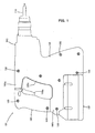
FIG. 1 is an external view showing an entire structure of a battery-powered hammer drill according to an embodiment. -
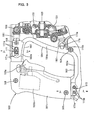
FIG. 2 is a side view showing an internal structure of the battery-powered hammer drill by broken line and partly in section. -
FIG. 3 shows a vibration-proof structure of a handgrip in its initial state (mounted state) in which the handgrip is in the most rearward position. -
FIG. 4 shows the vibration-proof structure of the handgrip in the state of maximum displacement in which the handgrip is in the most forward (housing-side) position. -
FIG. 5 is a sectional view taken along line A-A inFIG. 3 . -
FIG. 6 is a sectional view taken along line B-B inFIG. 3 . -
FIG. 7 is a view showing an entire hammer drill. -
FIG. 8 (A) is a view illustrating an output shaft region,FIG. 8 (B) is a view from a direction shown by the arrow A, andFIG. 8 (C) is a view from a direction shown by the arrow B. -
FIG. 9 is an enlarged view of the output shaft region. -
FIG. 10 is a viewillustrating the state in which a front housing is removed. -
FIG. 11 is a view illustrating the state in which a right housing is removed. -
FIG. 12 (A) is a sectional view taken along line C-C inFIG. 11 ,FIG. 12 (B) is a sectional view taken along line D-D inFIG. 11 . -
FIG. 13 is a cross-sectional view showing a rear end part of the inner housing. - Each of the additional features and method steps disclosed above and below may be utilized separately or in conjunction with other features and method steps to provide and manufacture improved power tools and method for using such power tools and devices utilized therein. Representative examples of the present invention, which examples utilized many of these additional features and method steps in conjunction, will now be described in detail with reference to the drawings. This detailed description is merely intended to teach a person skilled in the art further details for practicing preferred aspects of the present teachings and is not intended to limit the scope of the invention. Only the claims define the scope of the claimed invention. Therefore, combinations of features and steps disclosed within the following detailed description may not be necessary to practice the invention in the broadest sense, and are instead taught merely to particularly describe some representative examples of the invention, which detailed description will now be given with reference to the accompanying drawings.
A representative example is now described with reference toFIGS. 1 to 6 . In this example, a battery-powered hammer drill is explained.FIG. 1 shows an entire structure of thehammer drill 101 according to this example, andFIG. 2 is a side view showing an internal structure of thehammer drill 101 by broken line and partly in section. As shown inFIG. 1 , thehammer drill 101 mainly includes abody 103 that forms an outer shell of thehammer drill 101, ahammer bit 119 detachably coupled to the tip end region of thebody 103 via atool holder 137, ahandgrip 109 connected to thebody 103 on the side opposite to thehammer bit 119 and designed to be held by a user, and abattery pack 107 attached to the underside of thebody 103. Thebody 103, thehammer bit 119 and thehandgrip 109 are features that correspond to the "power tool body", the "tool bit" and the "handle", respectively. Thehammer bit 119 is held by thetool holder 137 such that it is allowed to reciprocate with respect to the tool holder in its axial direction and prevented from rotating with respect to the tool holder in its circumferential direction. In the present example, for the sake of convenience of explanation, the side of thehammer bit 119 is taken as the front side and the side of thehandgrip 109 as the rear side. - As shown in
FIG. 2 , thebody 103 mainly includes ahousing 105 that houses anelectric motor 111, amotion converting mechanism 113, a striking mechanism 115 and apower transmitting mechanism 117. The rotating output of theelectric motor 111 is appropriately converted into linear motion via themotion converting mechanism 113 and transmitted to the striking mechanism 115. Then, an impact force is generated in the axial direction of thehammer bit 119 via the striking mechanism 115. Further, thepower transmitting mechanism 117 appropriately reduces the speed of the rotating output of theelectric motor 111 and then transmits the rotating output to thehammer bit 119. As a result, thehammer bit 119 is caused to rotate in the circumferential direction. Theelectric motor 111 is driven when anelectric switch 109b is turned on by depressing atrigger 109a on thehandgrip 109. - The
electric motor 111 is disposed in a lower region within thehousing 105 and arranged such that its axis of rotation extends obliquely with respect to the vertical direction and transversely to the axial direction of thehammer bit 119. Themotion converting mechanism 113 mainly includes adriving gear 121 that is rotated by theelectric motor 111, a drivengear 123 that engages with thedriving gear 121 and is rotated in a vertical plane, arotating element 127 that rotates together with the drivengear 123 via anintermediate shaft 125, a swinging member in the form of a swingingring 129 that is caused to swing in the axial direction of thehammer bit 119 by rotation of therotating element 127, and a driving element in the form of acylindrical piston 141 that is caused to reciprocate by swinging movement of the swingingring 129. The swingingring 129 is rotatably supported on therotating element 127 via a bearing. Therotating element 127 and the swingingring 129 form a swinging mechanism. - The
cylindrical piston 141 has a closed end (closed rear end). Thecylindrical piston 141 is slidably disposed within thecylindrical tool holder 137 that is disposed coaxially with thecylindrical piston 141. Thecylindrical piston 141 is driven by swinging movement (by its components in the axial direction of the hammer bit 119) of the swingingring 129, and reciprocates along thetool holder 137. - The striking element 115 mainly includes a striking element in the form of a
striker 143 slidably disposed within the bore of thecylindrical piston 141, and an intermediate element in the form of animpact bolt 145 that is slidably disposed within thetool holder 137 and serves to transmit the kinetic energy of thestriker 143 to thehammer bit 119. Thestriker 143 is then driven (linearly moved) by pressure fluctuations of air (the action of an air spring) within an air chamber of thecylindrical piston 141 as a result of the sliding movement of thepiston 141. Thestriker 143 then collides with (strikes) theimpact bolt 145 which is slidably disposed within thetool holder 137, and transmits the striking force to thehammer bit 119 via theimpact bolt 145. Thecylindrical piston 141, thestriker 143 and theimpact bolt 145 form a bit striking mechanism. - The
power transmitting mechanism 117 mainly includes afirst transmission gear 131 that is caused to rotate in a vertical plane by theelectric motor 111 via theintermediate shaft 125, and asecond transmission gear 133 that is engaged with thefirst transmission gear 131 and coaxially mounted on thetool holder 137. The rotational driving force of thesecond transmission gear 133 is transmitted to thetool holder 137 and then to thehammer bit 119 held by thetool holder 137. - In the
hammer drill 101 thus constructed, when theelectric motor 111 is driven, a striking force is applied to thehammer bit 119 in the axial direction from themotion converting mechanism 113 via the striking mechanism 115, and at the same time, a rotating force is also applied to thehammer bit 119 in the circumferential direction via thepower transmitting mechanism 117. Thus, thehammer bit 119 performs a drilling operation on a workpiece (concrete) by a hammering movement in the axial direction and a drilling movement in the circumferential direction.
Thehammer drill 101 can be appropriately switched between a hammering operation mode in which only a striking force in the axial direction is applied to thehammer bit 119, and a hammer drill operation mode in which a striking force in the axial direction and a rotating force in the circumferential direction are applied to thehammer bit 119. This construction is not directly related to this invention and therefore will not be described. - Next, a vibration-proof structure of the
handgrip 109 is described with reference toFIGS. 3 to 6 .FIGS. 3 and4 show the vibration-proof structure of thehandgrip 109, andFIGS. 5 and 6 are sectional views taken along line A-A and line B-B inFIG. 3 , respectively. As shown inFIGS. 5 and 6 , thehollow housing 105 forming thebody 103 includes right and lefthousing halves housing 105 is split in the axial direction of thehammer bit 119.FIGS. 3 and4 show the state in which thehousing half 105L on the left side of thehammer drill 101 as viewed from the front is removed. On one of the right and lefthousing halves left housing half 105L, as shown inFIG. 5 , a plurality of cylindrical dowels 151 are integrally formed on its edge region on the mating face side (the inner surface side) and protrude in a direction perpendicular to the mating face. In theright housing half 105R, a plurality of dowel holes 153 are formed to correspond with the dowels 151. The dowels 151 are fitted in the dowel holes 153, and in this state, the right and lefthousing halves screws 155 through the dowels. - As shown in
FIGS. 3 and4 , thehandgrip 109 includes agrip part 161 extending in a vertical direction transverse to the axial direction of thehammer bit 119, upper andlower arms stay 164 that extends substantially parallel to thegrip part 161 and connects the extending ends of the upper andlower arms handgrip 109 is configured as a closed-loop integral frame structure. With this structure, the rigidity of thehandgrip 109 can be increased. Therefore, this structure is effective in preventing damage to thehandgrip 109 in the event of drop of thehammer drill 101. Thestay 164 is a feature that corresponds to the "transverse part". - Further, as shown in
FIGS. 5 and 6 , like thehousing 105, thehandgrip 109 includes right and left handgrip halves 109L, 109R into which thehandgrip 109 is split in the axial direction of thehammer bit 119. On one of the right and left handgrip halves 109L, 109R, or, for example, theleft handgrip half 109L, a plurality ofcylindrical dowels 167 are integrally formed on its edge region on the mating face side (the inner surface side) and protrude in a direction perpendicular to the mating face. In theright handgrip half 109R, a plurality of dowel holes 168 are formed to correspond with thedowels 167. Thedowels 167 are fitted in the dowel holes 168, and in this state, the right and left handgrip halves 109L, 109R are joined to each other byscrews 169 through the dowels. - As shown in
FIG. 1 , a rear region of thehousing 105 is generally U-shaped in side view, having an upper extendingportion 105a extending to theupper arm 162 of thehandgrip 109, a lower extendingportion 105b extending to thelower arm 163, and anintermediate portion 105c extending therebetween. Openings are formed in a lower surface and a rear end surface of the upper extendingportion 105a, an upper surface of the lower extendingportion 105b and a rear surface of theintermediate portion 105c. The upper andlower arms stay 164 of thehandgrip 109 are inserted into the upper extendingportion 105a, the lower extendingportion 105b and theintermediate portion 105c, respectively, through the openings, and can move in the axial direction of thehammer bit 119. The lower extendingportion 105b is a feature that corresponds to the "extending region". Further, thebattery pack 107 is detachably mounted on the underside of the lower extendingportion 105b of thehousing 105. Specifically, the lower extendingportion 105b also serves as a mount for thebattery pack 107. - Thus, all parts of the
handgrip 109 except thegrip part 161 are held (enclosed) by the generally U-shaped rear region of thehousing 105 from laterally outward. In this state, thehandgrip 109 is supported in such a manner as to be movable with respect to thehousing 105 in the axial direction of thehammer bit 119. Further, thehandgrip 109 is connected at the front end to thehousing 105 via upper andlower coil springs FIGS. 3 and4 , theupper coil spring 181 is elastically disposed between a front end surface of theupper arm 162 and a rear wall surface of aninner housing 185 disposed within thehousing 105. Thelower coil spring 183 is elastically disposed between a front lower portion of thestay 164 and the rear wall surface of theinner housing 185. - The right and left side surfaces of the upper and
lower arms stay 164 in thehandgrip 109 havesmooth surfaces hammer bit 119, in part or in entirety. Thesmooth surfaces lower arms hammer bit 119, and thesmooth surface 164a of thestay 164 extends vertically in a direction transverse to the axial direction of thehammer bit 119. Thesmooth surfaces FIG. 5 ) of the openings of the upper extendingportion 105a, the lower extendingportion 105b and the intermediate portion lost. - Specifically, the opening edges 165 form sliding guide surfaces which slide in surface contact with the
smooth surfaces smooth surfaces lower arm 163 and thestay 164 and the opening edges of the lower extendingportion 105b and theintermediate portion 105c, which are not shown, are similarly configured as the structure of contact between thesmooth surface 162a of theupper arm 162 and theopening edge 165 of the upper extendingportion 105a, which is shown inFIG. 5 . With this construction, rattling of thehandgrip 109 with respect to thehousing 105 can be reduced in a horizontal (lateral) direction transverse to the axial direction of thehammer bit 119, which results in stabilization of relative sliding movement of thehandgrip 109 in the axial direction of thehammer bit 119. Thesmooth surfaces smooth surfaces portion 105a and the lower extendingportion 105b and thesmooth surface 164a of thestay 164 are features that correspond to the "first sliding region." and the "second sliding region", respectively. - Slide guides 171, 173, 175 are provided between the
upper arm 162 of thehandgrip 109 and the upper extendingportion 105a of thehousing 105, between thelower arm 163 and the lower extendingportion 105b and between thestay 164 and theintermediate portion 105c. The upper and lower slide guides 171, 173 are features that correspond to the " guide". As shown inFIGS. 3 to 5 , theupper slide guide 171 includes aslot 171a that is formed generally in the middle of theupper arm 162 in its extending direction, and aprotrusion 171b that is formed on the upper extendingportion 105a and slidably inserted through theslot 171a. The above-described cylindrical dowel 151 formed on theleft housing half 105L also serves as theprotrusion 171b. In this embodiment, two dowels 151 are disposed side by side in the axial direction of thehammer bit 119 in such a manner as to serve also asprotrusions 171b. Theslot 171a is formed through the upper arm in the lateral direction (seeFIG. 5 ) and has a predetermined length extending in the axial direction of the hammer bit 119 (seeFIGS. 3 and4 ). - As shown in
FIGS. 3 ,4 and6 , thelower slide guide 173 includes protrusions in the form of twometal pins 173b mounted to a rear end portion (an area of connection with the grip part 161) of thelower arm 163, andconcave grooves 173a (shown by two-dot chain line inFIGS. 3 and4 ) formed in the inner surface of the upper rear-end portion of the lower extendingportion 105b (in the inner surfaces of the right and lefthousing halves concave grooves 173a. The twometal pins 173b extend through thelower arm 163 in the lateral direction and are disposed side by side with a predetermined spacing therebetween in the axial direction of thehammer bit 119. The extending ends (axial ends) of the metal pins 173b are engaged in theconcave grooves 173a. Theconcave grooves 173a have a predetermined length extending in the axial direction of thehammer bit 119. The right and lefthousing halves concave grooves 173a are formed of a different material from the metal pins 173b, for example, a light material such as synthetic resin and aluminum. The sliding structure formed of heterogeneous materials can obtain higher sliding ability. - Further, as shown in
FIGS. 3 and4 , theintermediate slide guide 175 includes aconcave groove 175a and acircular projection 175b (shown by two-dot chain line in the drawings). Theconcave groove 175a is formed in the side surface of the front lower portion of thestay 164 and has a predetermined length extending in the axial direction of thehammer bit 119. Thecircular projection 175b extends inward from the inner surface of theintermediate portion 105c of thehousing 105 and is slidably engaged in theconcave groove 175a. - As described above, by provision of the upper, lower and intermediate slide guides 171, 173, 175, the
handgrip 109 is prevented from moving in a vertical direction transverse to the axial direction of thehammer bit 119 with respect to thehousing 105, and thus rattling of thehandgrip 109 in the vertical direction is reduced. - The
hammer drill 101 according to this example is constructed as described above.FIG. 3 shows an initial state of the handgrip 109 (the state in which thehandgrip 109 is mounted to the housing 105). In this state, thehandgrip 109 is biased rearward away from thehousing 105 by the spring force of the coil springs 181, 183, and at least theprotrusions 171b of theupper slide guide 171 are held in contact with the front end of theslot 171a.FIG. 4 shows the state in which thehandgrip 109 is moved from the initial state to thehousing 105 side (forward) as far as possible and theprotrusions 171b come in contact with the rear end of theslot 171a (the state of maximum displacement). The maximum amount of relative movement (displacement) of thehandgrip 109 is shown by L inFIG. 4 . - An operation using the
hammer drill 101 is performed while the user holds thegrip part 161 of thehandgrip 109 and applies a forward pressing force to thehammer drill 101. Specifically, the operation is performed in the state in which theprotrusions 171b, the metal pins 173b and thecircular projection 175b of the upper, lower and intermediate slide guides 171, 173, 175 are placed between the rear and front ends of theslot 171a and theconcave grooves handgrip 109 is allowed to move with respect to thehousing 105 in the axial direction of thehammer bit 119. Therefore, during operation, vibration which is caused in thehousing 105 and transmitted from thehousing 105 to thehandgrip 109 can be reduced by the coil springs 181, 183. - In this example, as described above, the
handgrip 109 is elastically connected to thehousing 105 by the upper andlower coil springs housing 105 for relative movement in the axial direction of thehammer bit 119. Therefore, the coil springs 181, 183 absorb vibration by linear deformation in the axial direction of the hammer bit, so that the vibration absorption efficiency of the coil springs 181, 183 can be enhanced. - In the known rotary handgrip in which one end of the grip part in the extending direction (the vertical direction) is connected to the hammer body via a coil spring and the other end of the grip part is pivotally supported on a pivot, if an attempt is made to obtain a desired vibration proofing effect by causing the direction of deformation of the coil spring to be closer to the axial direction of the hammer bit, the distance between the pivot and the coil spring is widened, so that the size of the handgrip increase in the vertical direction. Therefore, like in this example, with a construction in which the
handgrip 109 linearly moves with respect to the hammer body in the axial direction of thehammer bit 119 in order to obtain a vibration proofing effect, the vertical length of thehandgrip 109 is not restricted, so that the size of thehandgrip 109 can be reduced. - Further the
lower arm 163 of thehandgrip 109 can be slidably supported with stability by the lower extendingportion 105b of thehousing 105, and in addition, the lower extendingportion 105b also serves as a mount for thebattery pack 107. Therefore, a rational supporting structure can be realized. - Further a rear region of the
housing 105 is generally U-shaped in side view, having the upper and lower extendingportions intermediate portion 105c extending therebetween, and the upper andlower arms stay 164 of thehandgrip 109 are inserted into this generally U-shaped region. With this construction, the relatively widesmooth surfaces arms stay 164, so that rattling of thehandgrip 109 can be reduced in the lateral direction. Further, by provision of the upper, lower and intermediate slide guides 171, 173, 175, rattling of thehandgrip 109 can be reduced in the vertical direction. - As described above rattling of the
handgrip 109 can be reduced in any direction except the axial direction of thehammer bit 119. Therefore, even if the spring constant of the coil springs 181, 183 is reduced, a sufficient vibration proofing effect can be obtained. Further, such a vibration-proof handgrip 109 feels comfortable to use. - The hammer drill is described as a representative example , but the present invention can also be applied to a hammer in which the
hammer bit 119 performs only the striking movement in the axial direction, or a cutting power tool, such as a reciprocating saw and a jig saw, which performs a cutting operation on a workpiece by reciprocating movement of a blade.
A battery-powered power tool is described in which theelectric motor 111 is powered from thebattery pack 107, but the present invention can also be applied to a power tool in which theelectric motor 111 is AC powered. - An embodiment of the invention is now described with reference to the drawings of
FIGS. 7 to 13 .
FIG. 7 is a view showing anentire hammer drill 1 as a representative embodiment. In thehammer drill 1, abattery 2 is mounted on the underside of the rear (shown on the left inFIG. 7 ) of the hammer drill and amotor 3 is housed in front of thebattery 2 such that anoutput shaft 4 is oriented upward. An output section is disposed above themotor 3. In theoutput section 5, anintermediate shaft 6 is supported in the longitudinal direction, and afirst gear 7 and aswash bearing 8 are fitted on theintermediate shaft 6 one behind the other such that they can individually rotate separately from theintermediate shaft 6. A clutch sleeve 9 is arranged between thefirst gear 7 and theswash bearing 8 such that it can rotate together with theintermediate shaft 6 and can slide in its axial direction. Further, acylindrical tool holder 10 is supported above theintermediate shaft 6 and in parallel therewith, and asecond gear 11 that engages with thefirst gear 7 is integrally fitted on thetool holder 10. Apiston cylinder 12 is loosely fitted in thetool holder 10 such that it can reciprocate, and astriker 13 is disposed within thepiston cylinder 12. The rear end of thepiston cylinder 12 is connected to anarm 14 of theswash bearing 8. Further, animpact bolt 15 is housed within a front portion of thepiston cylinder 12 such that it can move in the longitudinal direction. - When an operating knob (not shown) is operated to slide the clutch sleeve 9 forward into engagement only with the
first gear 7, rotation of theintermediate shaft 6 is transmitted to thefirst gear 7 via the clutch sleeve 9 and then to thetool holder 10 via thesecond gear 11. As a result, a bit (not shown) coupled to the front end of thetool holder 10 rotates together with the tool holder 10 ("drill mode"). On the other hand, when the clutch sleeve 9 is slid rearward into engagement only with theswash bearing 8, rotation of theintermediate shaft 6 is transmitted to theswash bearing 8 via the clutch sleeve 9. As a result, thearm 14 swings in the longitudinal direction and moves thepiston cylinder 12 back and forth, which in turn causes thestriker 13 to be interlocked to strike theimpact bolt 15 and thus strike the bit ("hammer mode"). Further, when the clutch sleeve 9 is engaged with both thefirst gear 7 and theswash bearing 8, both thefirst gear 7 and theswash bearing 8 rotate, so that the bit is struck while rotating ("hammer drill mode") - A housing of the
hammer drill 1 has two parts, or abody housing 20 and afront housing 21. Thebody housing 20 covers all over a rear region of thehammer drill 1 which includes a rear part of theoutput section 5 and themotor 3, and thefront housing 21 covers a front part of theoutput section 5 in front of thebody housing 20. Further, the rear part of theoutput section 5 is housed within aninner housing 22 installed within thebody housing 20. - As shown in
FIG. 10 and FIG. 12 (A), thebody housing 20 is formed by housing halves in the form of a pair of right and lefthousings Cylindrical bosses 25 each having a threaded bore extend from an inner surface of theleft housing 23, andcylindrical bosses 26 each having a through bore extend from an inner surface of theright housing 24. When the right and lefthousings bosses 26 are fitted on thebosses 25 in a coaxially butted manner. Therefore, the right and lefthousings body housing 20 by insertingscrews 27 through each of thebosses 26 from theright housing 24 side and threadably into the associatedbosses 25. Further, ahandle 28 is connected to an upper portion of the rear end of thebody housing 20. The handle 28 houses aswitch 16 which is actuated to drive themotor 3, and thehandle 28 has aswitch lever 17 which is depressed to turn on theswitch 16. - Further, the
inner housing 22 has a box-like shape having an open front end and a closed rear end. Theinner housing 22 supports a rear end of theintermediate shaft 6 via aball bearing 29 which is provided within the rear of theinner housing 22. Further, aninsert hole 30 is formed through the bottom of theinner housing 22, and theoutput shaft 4 of themotor 3 is inserted into theinner housing 22 through theinsert hole 30 such that aball bearing 31 mounted on theoutput shaft 4 is fitted in theinsert hole 30. In this manner, theinner housing 22 supports theoutput shaft 4. Themotor 3 here is arranged within thebody housing 20 in a tilted position in which the lower end of theoutput shaft 4 is located forward of the upper end of theoutput shaft 4. The upper end of the output shat 4 is inserted into theinner housing 22 through theinsert hole 30 and engaged with abevel gear 18, so that rotation of theoutput shaft 4 can be transmitted to theintermediate shaft 6. Thebevel gear 18 is fixedly mounted on the rear end portion of theintermediate shaft 6 and located at an input end of theoutput section 5. - As shown in
FIG. 8 , asleeve 32 is press-fitted onto theoutput shaft 4 on the upper end of theball bearing 31 and a sealing material in the form of anoil seal 33 which is retained within theinsert hole 30 is held in sliding contact with thesleeve 32, so that theinner housing 22 is sealed. A retainingring 34 is engaged on theoutput shaft 4 on the upper end of thesleeve 32. Further, a constricted part (groove) 35 is formed in theoutput shaft 4 at a position corresponding to the opening edge of theinsert hole 30, and astopper ring 36 is fitted in theconstricted part 35. Thestopper ring 36 is held in contact with an outer end surface of theball bearing 31 fitted on theoutput shaft 4. - A bearing
retainer 37 is mounted on the opening edge of theinsert hole 30 of theinner housing 22. The bearingretainer 37 has a semicircular arc shape to be arranged in contact with half of an circumferential portion of the outer end surface of theball bearing 31. A pair of ring-shaped mountingparts 38 extend radially outward from both end portions (upper and lower portions in the vertical direction as viewed inFIGS. 8(B) and FIG. 8(C) ) of the bearingretainer 37. Anut 39 is fixedly mounted on each of the mountingparts 38, and a pair of engagingclaws 40 are formed on the bearingretainer 37 between the mountingparts 38 and folded up away from thenut 39 into an L-shape. - Correspondingly, a pair of
screw fastening parts 41 are formed on upper and lower portions (as viewed inFIGS. 8 (B) and FIG. 8 (C) ) of theinner housing 22. Thescrew fastening parts 41 each have a thickness large enough to be engaged and locked by the engagingclaws 40 and each have aprotrusion 42 on its end which faces an end of the other. - When the engaging
claws 40 of the bearingretainer 37 are engaged on thescrew fastening parts 41, the engagingclaws 40 come into contact with theprotrusions 42 and thus lock the bearingretainer 37 against vertical movement (as viewed inFIGS. 8 (B) and FIG. 8 (C) ). Thus, the bearingretainer 37 is positioned in a mounting position in which the centers of the mountingpart 38 and thenut 39 are aligned with a through hole (not shown) of thescrew fastening part 41. In this state, asetscrew 43 is inserted through thescrew fastening part 41 and the mountingpart 38 and screwed into thenut 39. Thus, the bearingretainer 37 is fastened in contact with the opening edge of theinsert hole 30 and the outer end surface of theball bearing 31, and thus, at the opening edge of theinsert hole 30, it prevents the ball bearing 31 from slipping out. Thus, thesleeve 32 abuts against theball bearing 31 mounted on theoutput shaft 4, from above or from the upper end of theoutput shaft 4, while the bearingretainer 37 also abuts against the ball bearing 31 from below or from the opposite side, so that theoutput shaft 4 is positioned without rattling in its axial direction. - Further,
cylindrical portions 44 are formed on upper and lower portions of the rear end of theinner housing 22 and each have apositioning hole 45 through which the associatedboss 25 of theleft housing 23 is inserted in the assembled state of thebody housing 20. In the state in which theboss 25 is inserted through thepositioning hole 45, as shown inFIG. 12 (A) , an end surface of thecylindrical portion 44 is held in contact with arib 46 which extends from the outer periphery of theboss 25 to an inner surface of theleft housing 23. In the state in which theinner housing 22 is thus connected to theleft housing 23, theright housing 24 is connected to theleft housing 23. At this time, theboss 26 of theright housing 24 comes into contact with the end surface of thecylindrical portion 44, so that thecylindrical portion 44 is centrally positioned in the lateral direction. Specifically, assembling of thebody housing 20 by the screws and fixed positioning of theinner housing 22 by thebosses - Furthermore, the front end of the
inner housing 22 or a protrudingpart 47 protrudes forward of the front open end of thebody housing 20, and an O-ring 49 is fitted in acircumferential groove 48 formed in an outer surface of the protrudingpart 47. - The
front housing 21 has a rear end opening which conforms to the front end opening of thebody housing 20. Thefront housing 21 has a tapered cylindrical shape covering the front portion of theinner housing 22 and the front ends of thetool holder 10 and theintermediate shaft 6. A bearing 50 for supporting thetool holder 10 and aball bearing 51 for supporting a front end of theintermediate shaft 6 are formed on the inside of thefront housing 21. In order to assemble thefront housing 21 and thebody housing 20, as shown inFIG. 12 (B) , ascrew 53 is inserted through a throughhole 52 formed in the rear end of thefront housing 21, and then screwed into a threadedhole 54 formed in the front end of each of the left andright housings rib 55 which is formed on the outer surface of the protrudingpart 47 of theinner housing 22 and extends in the circumferential direction is held between thebody housing 20 and thefront housing 21, and the O-ring 49 is held in contact with the inner surface of thefront housing 21. - An
LED 56 is housed in a front lower portion of thebody housing 20 below themotor 3 and oriented forward and obliquely upward such that it can illuminate a region ahead of the bit mounted to thetool holder 10. Particularly in this embodiment, the lower portion of thebody housing 20 is configured to correspond to the tilt of themotor 3, or specifically, it has an oblique shape gradually protruding forward toward its lower end. TheLED 56 is located substantially at the protruding end of the inclined portion of thebody housing 20, so that it can effectively illuminate an area to be worked on, from the front end of thebody housing 20. - An air-bleeding
hole 57 is formed in the rear end of theinner housing 22 behind thepiston cylinder 12 and extends through it in the longitudinal direction as shown inFIG. 13 . Further, acylindrical portion 58 having a bottom is formed on the rear surface of theinner housing 22 and configured to communicate with the air-bleedinghole 57. Thecylindrical portion 58 has a longitudinal axis perpendicular to the air-bleedinghole 57 such that it has an open top or end on the right side (as viewed inFIG. 13 ). Thecylindrical portion 58 is filled with a feltfilter 59, and afilter cap 60 is fitted to the open top of thecylindrical portion 58 in such a manner as to prevent thefilter 59 from slipping out. Thefilter cap 60 has a cylindrical shape having a bottom and having an open top which faces thefilter 59, and anexhaust hole 61 is formed through the center of the closed bottom along its axis of the cylindrical filter cap. Further, aprotrusion 62 is formed on the inner surface of theright housing 24 and arranged and configured to extend close to theexhaust hole 61 of thefilter cap 60 in the assembled state, in order to prevent removal of thefilter cap 60. - When the temperature within the
inner housing 22 increases by heat generation which is caused by operation of theoutput section 5 and the inside air expands, the air is introduced into thecylindrical portion 58 via the air-bleedinghole 57 and discharged through theexhaust hole 61 of thefilter cap 60. At this time, even if lubricating oil (such as grease) within theinner housing 22 enters thecylindrical portion 58 through the air-bleedinghole 57 together with the air, thefilter 59 can absorb it. Furthermore, even if lubricating oil overflows thefilter 59, thefilter cap 60 can hold it back, so that it is prevented from entering thebody housing 20 through theexhaust hole 61. - Particularly in this embodiment, the
exhaust hole 61 is arranged to be oriented in a direction perpendicular to the longitudinally extending air-bleedinghole 57 and to face toward theright housing 24. Therefore, a rational construction can be realized in which, concurrently with the assembling operation of theright housing 24, theprotrusion 60 serves to prevent removal of thefilter cap 60. - In the
hammer drill 1 having the above-described construction, in order to assemble thebody housing 20 and fixedly position theinner housing 22 in thebody housing 20 at the same time as described above, themotor 3 and theinner housing 22 with theoutput section 5 housed therein are set on theleft housing 23 to which thehandle 28 is already connected, and in this state, theright housing 24 is set on theleft housing 23 from above and fastened thereto by screws. In order to mount theoutput shaft 4 to theinner housing 22, first, thestopper ring 36, theball bearing 31, thesleeve 32 and the retainingring 34 are mounted in respective positions on theoutput shaft 4. In this state, theoutput shaft 4 is inserted into theinsert hole 30 to which theoil seal 33 is mounted. Then the upper end of theball bearing 31 is fitted in anengagement portion 30a which is formed in theinsert hole 30 and shaped to fit theball bearing 31. Finally, the bearingretainer 37 is fastened to theinner housing 22 by thesetscrews 43. - Thereafter, the
front housing 21 is mounted to the front of thebody housing 20 in such a manner as to cover it from the front of theoutput section 5, and fastened by screws. In this manner, as shown inFIG. 7 , assembly of thehammer drill 1 is completed. In this state, thefront housing 21 is integrally connected not only to thebody housing 20 but to the protrudingpart 47 of theinner housing 22, so that rigidity of the connection between thebody housing 20 and thefront housing 21 can be ensured. - When, for example, the
output section 5 is in need of repair or maintenance, for this purpose, as shown inFIG. 10 , only thefront housing 21 can be removed while thebody housing 20 is held as-is, by unscrewing thescrews 53 that fixate thefront housing 21 to thebody housing 20. - Further, when, for example, the
motor 3 side is in need of repair or maintenance, for this purpose, as shown inFIG. 11 , only theright housing 24 can be removed while thefront housing 20 is held as-is, by unscrewing thescrews 27 that fixate the right and lefthousings screws 53 that fixate thefront housing 21 to theright housing 24. - Thus, according to the
hammer drill 1 in this representative embodiment of the invention, theinner housing 22 provided within thebody housing 20 houses part of theoutput section 5, protrudes forward from thebody housing 20 and is fixedly held between the right and lefthousings front housing 21 is lapped on the protrudingpart 47 of theinner housing 22 and mounted to the front end of thebody housing 20, such that the right and lefthousings front housing 21 can be individually removed. As a result, rigidity of the connection between thebody housing 20 and thefront housing 21 can be ensured. In addition, in order to repair either of thebody housing 20 side and thefront housing 21 side, only the one on the side to be repaired can be removed. Thus, workability relating to repairs or other similar operations can be improved. - Particularly in this embodiment, the right and left
housings cylindrical bosses housings bosses housings inner housing 22 has thepositioning hole 45 through which theboss 25 is inserted in the assembled state of thebody housing 20, so that theinner housing 22 can be fixedly positioned while the right and lefthousings inner housing 22 can be efficiently and accurately mounted in thebody housing 20. Therefore, the positioning relationship between themotor 3 and theoutput section 5 can be stabilized and no problem is caused in transmission of rotation. - Further, the
motor 3 is housed under theinner housing 22 and arranged such that theoutput shaft 4 is oriented upward and themotor 3 is in a tilted position in which the lower end of theoutput shaft 4 is located forward of the upper end of theoutput shaft 4. Further, the upper end of theoutput shaft 4 is inserted into theinner housing 22 and engaged with thebevel gear 18 at the input end of theoutput section 5. With this construction, transmission of rotation from themotor 3 to theoutput section 5 can be ensured. - Further, in this embodiment, the
rib 55 which extends in the circumferential direction on theinner housing 22 is held between thebody housing 20 and thefront housing 21, but, in place of therib 55, discontinuously extending projections may be used. Further, without using this structure of holding the rib, it may be constructed such that the protruding part of the inner housing is simply held in contact with the inner surface of the front housing. - Further, the number and configuration of the positioning holes 45 are not limited to those in the above embodiment. For example, they may be formed not in the cylindrical portion but in a plate-like part, or depending on the position of the bosses, they may be formed not only on the rear of the inner housing but on the top and the bottom of the inner housing. It is naturally possible to dispense with the positioning holes, and it may be constructed to hold the outer surface of the inner housing by a rib or a recessed seat formed in the inner surface of a housing part
- Further, the hammer drill is not limited to the type in which the motor is housed in a tilted position within the front lower portion of the hammer drill. For example, it may be constructed such that the motor is housed not in a tilted position but in a vertical position, or such that the motor is housed behind the output section and oriented forward. In the above-described embodiment, however, the motor is located forward of the heavy battery, so that the hammer drill can have a better balance as a whole. Further, the handle is located right behind the output section and on the axis of the bit, so that the hammer drill can be pressed forward at a rearward position nearer to the bit on the axis of the bit. Therefore, ease of use can be enhanced.
- Other design changes or modifications can also be made to the other parts. For example, in the output section, a crank mechanism may be used in place of the swash bearing, or a fixed cylinder and a piston which reciprocates with respect to the cylinder may be used in place of the piston cylinder. Or an AC power source may be used instead of the DC power source.
- The present invention is not limited to the hammer drill, but it can also be applied to other power tools, such as an electric hammer, an electric drill and an impact driver, in which its housing can be separated into a body housing and a front housing.
- Further, according to the
hammer drill 1, an end of thesleeve 32 press-fitted onto theoutput shaft 4 is held in contact with one end surface of theball bearing 31, and the bearingretainer 37 on theinner housing 22 is held in contact with the other end surface of theball bearing 31. Thus, theball bearing 31 is held between thesleeve 32 and the bearingretainer 37, so that theoutput shaft 4 is positioned in its axial direction. Thus, theoutput shaft 4 can be accurately positioned by a simple structure utilizing the existingsleeve 32. As a result, theoutput shaft 4 can be held in proper engagement with thebevel gear 18 and thus obtain a favorable durability. - Particularly, by provision of the bearing
retainer 37 having a semicircular arc shape to be arranged in contact with half of a circumferential portion of the outer end surface of theball bearing 31, the bearingretainer 37 can be formed in a minimum structure required to position theoutput shaft 4. As a result, the cost of the bearingretainer 37 can be reduced, and the bearingretainer 37 can be easily mounted to theinner housing 22. - Further, by provision of the engaging
claws 40 which are formed on the bearingretainer 37 and which are engaged with thescrew fastening parts 41 formed on theinner housing 22 and thus position the bearingretainer 37 in a mounting position on theinner housing 22, the bearingretainer 37 can be more easily mounted to theinner housing 22. - Further, the output shaft of the motor is provided with a positioning structure, but, even in a construction, for example, in which an intermediate shaft is supported in parallel to the output shaft between the output shaft and a gear at the input end of the output section such that rotation of the output shaft can be transmitted to the gear at the input end and the intermediate shaft is engaged with the gear, any positioning structure having a bearing retainer can also be used only if a sealing sleeve is provided on the bearing part of the intermediate shaft.
- Further, the bearing retainer may be mounted from the other half side from a direction opposite from the mounting direction in the above-mentioned embodiment, or from above the output shaft. The bearing retainer may have a shape other than the semicircular arc shape, such as a C-shape or a ring-like shape. Further, it is not limited to one, but a plurality of bearing retainers having, for example, a short arcuate shape can also be mounted.
In addition, in relation to mounting of the bearing retainer to the housing, design changes or modifications can also be appropriately made. For example, the bearing retainer may be fastened by screws from the side of the opening of the insert hole, or the engaging claws may be dispensed with.
Further, the bearing is not limited to the ball bearing, but a needle bearing, bearing metal and other types of bearings can also be used according to this invention. Naturally, the power tool to be applied includes not only the hammer drill, but other types of power tools. -
- 101 hammer drill (hand-held power tool)
- 103 body (power tool body)
- 105 housing
- 105a upper extending portion
- 105b lower extending portion
- 105c intermediate portion
- 105L left housing half
- 105R right housing half
- 107 battery pack
- 109 handgrip (handle)
- 109a trigger
- 109b electric switch
- 109L left handgrip half
- 109R right handgrip half
- 111 electric motor
- 113 motion converting mechanism
- 115 striking mechanism
- 117 power transmitting mechanism
- 119 bit (tool bit)
- 121 driving gear
- 123 driven gear
- 125 intermediate shaft
- 127 rotating element
- 129 swinging ring
- 131 fist transmission gear
- 133 second transmission gear
- 137 tool holder
- 141 cylindrical piston
- 143 striker
- 145 impact bolt
- 151 dowel
- 153 dowel hole
- 155 screw
- 161 grip part
- 162 upper arm
- 162a smooth surface
- 163 lower arm
- 163a smooth surface
- 164 stay (transverse part)
- 164a smooth surface (sliding surface)
- 165 opening edge
- 167 dowel
- 168 dowel hole
- 169 screw
- 171 upper slide guide (guide)
- 171 a slot
- 171b protrusion
- 173 lower slide guide (guide)
- 173a concave groove
- 173b metal pin
- 175 intermediate slide guide
- 175a concave groove
- 175b circular projection
- 181 upper coil spring (elastic element)
- 183 lower coil spring (elastic element)
- 185 inner housing
Claims (14)
- A power tool comprising:a motor (3; 111);an output section (5; 113, 115, 117) which is driven by the motor (3; 111);a first housing (20; 105) which houses the motor (3; 111);a second housing (21) which houses the output section (5; 113, 115, 117) at least in part, wherein the second housing (21) is coupled to the first housing (20; 105);wherein the first housing (20; 105) is provided by assembling housing components (23, 24; 105L, 105R), and the second housing (21) is coupled to each of the housing components (23, 24; 105L, 105R), and wherein each of the housing components (23, 24; 105L, 105R) and the second housing (21) are detachably coupled,characterized in thateach of the housing components (23, 24; 105L, 105R) has a boss (25, 26) extending from an inner surface of the housing components (23, 24; 105L, 105R), wherein the first housing (20) is provided by coupling each housing components (23, 24; 105L, 105R) by means of bosses (25, 26), anda third housing (22) has an engaging hole (45) through which the boss (25) is inserted, and wherein the third housing (22) is fixedly positioned by engaging the boss (25) into the engaging hole (45) when the housing components (23, 24; 105L, 105R) are coupled.
- The power tool according to claim 1, wherein the second housing (21) is secured to each of the housing components (23, 24; 105L, 105R) respectively by means of screws (53).
- The power tool according to claim 1 or 2, wherein
the third housing (22) is cramped by the housing components (23, 24; 105L, 105R) and has a protruding part (47) which protrudes from the first housing (20; 105), and
the second housing (21) houses the protruding part (47). - The power tool according to claim 3, wherein the first housing (20; 105) has a first opening through which the protruding part (47) protrudes, the second housing (21) has a second opening corresponding to the first opening, and
the second housing (21) is overlapped with the protruding part (47) and coupled to the first housing (20; 105) such that the second opening is aligned with the first opening. - The power tool according to claim 3 or 4, wherein the third housing (22) is cramped by the first housing (20; 105) and the second housing (21).
- The power tool according to any one of claims 1 to 5, wherein
the output section (5; 113, 115, 117) includes a shaft (6; 125) extending along a protruding direction of a protruding part (47) of a third housing (22), the protruding part (47) protrudes from the first housing (20; 105),
the motor (3) includes an output shaft (4) extending along a longitudinal direction of the output shaft (4),
the output shaft (4) has an upper end engaging to the output section (5; 113, 115, 117), and a lower end, and
the motor (3) is provided such that the motor (3) is in a tilted position in which the lower end of the output shaft (4) is located forward of the upper end of the output shaft (4) with respect to the protruding direction. - The power tool according to any one of claims 1 to 6, wherein the power tool is adapted to drive a tool bit (119) detachably coupled to the output section (5; 113, 115, 117), linearly in a predetermined direction, the power tool further comprises
a handle (28; 109) coupled to the first housing (20, 105) opposite to the tool bit (119) with respect to the predetermined direction via an elastic element (181, 183) such that the handle (28; 109) is slidable along the predetermined direction. - The power tool according to claim 7, wherein the handle (28; 109) extends along a cross direction crossing the predetermined direction, the first housing (20; 105) has an extending region (105b) extending to one side of the handle (28; 109) with respect to the cross direction.
- The power tool according to any one of claims 1 to 8, wherein
the output section (5; 113, 115, 117) is adapted to convert the rotating output of an output shaft (4) into linear motion and rotating motion of a tool bit (119) to be held in a tool holder (10), and
the axis of rotation of the output shaft (4) extends obliquely to the vertical direction and transversely to an axis of the linear and rotating motion of the tool bit (4). - The power tool according to claim 9, wherein
an upper end of the output shaft (4) is engaged with a bevel gear (18; 123) for transmitting the rotating output of the output shaft (4) to a shaft (6; 125), the bevel gear (18; 123) is mounted on a rear end portion of the shaft (6; 125) and located at an input end of the output section (5; 113, 115, 117). - The power tool according to any one of claims 1 to 10, wherein
the power tool further comprises a third housing (22) which is cramped by the housing components (23, 24; 105L, 105R), an insert hole (30) is formed through a bottom of the third housing (22), and
the motor comprises an output shaft (4) inserted into the third housing (22) through the insert hole (30) such that a bearing (31) mounted on the output shaft (4) is fitted in the insert hole (30) so that the third housing (22) supports the output shaft (4). - The power tool according to claim 11, wherein
a sleeve (32) is press-fitted onto the output shaft (4) on an upper end of the bearing (31) and held in sliding contact with a sealing material (33) provided between the output shaft (4) and the third housing (22) so that the third housing (22) is sealed, and
an end of the sleeve (32) is held in contact with one end surface of the bearing (31), and a bearing retainer (37) is mounted on the third housing (22) and held in contact with the other end surface of the bearing (31), whereby the bearing (31) is held between the sleeve (32) and the bearing retainer (37) such that the output shaft (4) is positioned in an axial direction of the output shaft (4). - The power tool according to claim 12, wherein
the bearing retainer (37) has a semicircular arc shape to be arranged in contact with half of a circumferential portion of the bearing (31). - The power tool according to claim 12 or 13, wherein
wherein an engaging claw (40) is formed on the bearing retainer (37) and the engaging claw (40) is engaged with an engagement part formed on the third housing (22) and thus positions the bearing retainer (37) in a mounting position on the third housing (22).
Applications Claiming Priority (4)
| Application Number | Priority Date | Filing Date | Title |
|---|---|---|---|
| JP2008167792A JP5197184B2 (en) | 2008-06-26 | 2008-06-26 | Rotary shaft positioning structure |
| JP2008167791A JP5171432B2 (en) | 2008-06-26 | 2008-06-26 | Electric tool |
| JP2008168770A JP5294726B2 (en) | 2008-06-27 | 2008-06-27 | Hand-held work tool |
| EP09008268A EP2138278B1 (en) | 2008-06-26 | 2009-06-24 | Handle for a power tool |
Related Parent Applications (1)
| Application Number | Title | Priority Date | Filing Date |
|---|---|---|---|
| EP09008268.6 Division | 2009-06-24 |
Publications (2)
| Publication Number | Publication Date |
|---|---|
| EP2384860A1 EP2384860A1 (en) | 2011-11-09 |
| EP2384860B1 true EP2384860B1 (en) | 2013-06-19 |
Family
ID=41171115
Family Applications (2)
| Application Number | Title | Priority Date | Filing Date |
|---|---|---|---|
| EP09008268A Active EP2138278B1 (en) | 2008-06-26 | 2009-06-24 | Handle for a power tool |
| EP11176543.4A Active EP2384860B1 (en) | 2008-06-26 | 2009-06-24 | Power tool housing |
Family Applications Before (1)
| Application Number | Title | Priority Date | Filing Date |
|---|---|---|---|
| EP09008268A Active EP2138278B1 (en) | 2008-06-26 | 2009-06-24 | Handle for a power tool |
Country Status (4)
| Country | Link |
|---|---|
| US (2) | US20090321101A1 (en) |
| EP (2) | EP2138278B1 (en) |
| AT (1) | ATE526120T1 (en) |
| RU (1) | RU2503813C2 (en) |
Cited By (1)
| Publication number | Priority date | Publication date | Assignee | Title |
|---|---|---|---|---|
| TWI789222B (en) * | 2022-01-26 | 2023-01-01 | 車王電子股份有限公司 | Impact tool with interchangeable grips |
Families Citing this family (42)
| Publication number | Priority date | Publication date | Assignee | Title |
|---|---|---|---|---|
| DE102009027317B4 (en) * | 2009-06-30 | 2019-12-05 | Robert Bosch Gmbh | Tool |
| DE102009054640A1 (en) * | 2009-12-15 | 2011-06-16 | Robert Bosch Gmbh | Hand tool |
| US8636081B2 (en) | 2011-12-15 | 2014-01-28 | Milwaukee Electric Tool Corporation | Rotary hammer |
| JP5726654B2 (en) * | 2011-07-01 | 2015-06-03 | 株式会社マキタ | Impact tool |
| US8915331B2 (en) * | 2011-09-29 | 2014-12-23 | Lincoln Industrial Corporation | Battery powered, handheld lubrication gun with display |
| JP2013151055A (en) | 2012-01-26 | 2013-08-08 | Makita Corp | Striking tool |
| EP2809470B1 (en) | 2012-02-03 | 2020-01-15 | Milwaukee Electric Tool Corporation | Rotary hammer |
| US9849577B2 (en) | 2012-02-03 | 2017-12-26 | Milwaukee Electric Tool Corporation | Rotary hammer |
| CN103291844A (en) * | 2012-03-02 | 2013-09-11 | 博世电动工具(中国)有限公司 | Electric tool and transmission device thereof |
| EP2749381B1 (en) * | 2012-12-25 | 2017-04-19 | Makita Corporation | Impact tool |
| US20150328764A1 (en) | 2013-02-01 | 2015-11-19 | Makita Corporation | Power tool |
| JP6096593B2 (en) | 2013-05-29 | 2017-03-15 | 株式会社マキタ | Reciprocating work tool |
| JP6085225B2 (en) * | 2013-06-27 | 2017-02-22 | 株式会社マキタ | Screw tightening electric tool |
| CN205651293U (en) * | 2013-07-15 | 2016-10-19 | 米沃奇电动工具公司 | Rotary power instrument |
| CN105829031B (en) * | 2013-12-20 | 2019-01-04 | 工机控股株式会社 | Electric tool |
| EP2898994A1 (en) | 2014-01-23 | 2015-07-29 | Black & Decker Inc. | Power tool with rear handle |
| EP2898992B1 (en) * | 2014-01-23 | 2016-05-04 | Black & Decker Inc. | Power tool with rear handle, method of manufacturing a part of a handle assembly for a power tool and method of disassembling a part of a handle assembly for a power tool |
| EP2898991B1 (en) * | 2014-01-23 | 2018-12-26 | Black & Decker Inc. | Rear handle |
| EP2898993B1 (en) | 2014-01-23 | 2019-01-30 | Black & Decker Inc. | Power tool |
| JP6501414B2 (en) * | 2014-03-25 | 2019-04-17 | 株式会社マキタ | Impact tool |
| JP6348337B2 (en) * | 2014-05-16 | 2018-06-27 | 株式会社マキタ | Reciprocating work tool |
| JP6278830B2 (en) * | 2014-05-16 | 2018-02-14 | 株式会社マキタ | Impact tool |
| RU2702181C2 (en) * | 2014-11-12 | 2019-10-04 | Макита Корпорейшн | Perimeter device |
| US10751868B2 (en) | 2014-11-28 | 2020-08-25 | Makita Corporation | Impact tool |
| JP6727828B2 (en) * | 2016-02-05 | 2020-07-22 | 株式会社マキタ | Power tools |
| JP6757226B2 (en) | 2016-10-07 | 2020-09-16 | 株式会社マキタ | Electric tool |
| EP3523096B1 (en) * | 2016-10-07 | 2020-12-30 | Gustav Klauke GmbH | Working tool |
| JP6863704B2 (en) * | 2016-10-07 | 2021-04-21 | 株式会社マキタ | Strike tool |
| JP6981744B2 (en) | 2016-10-07 | 2021-12-17 | 株式会社マキタ | Hammer drill |
| US10875168B2 (en) | 2016-10-07 | 2020-12-29 | Makita Corporation | Power tool |
| DE102017123102A1 (en) * | 2016-11-04 | 2018-05-09 | Makita Corporation | power tool |
| EA202092033A1 (en) | 2018-05-29 | 2021-03-22 | Робель Банбаумашинен Гмбх | IMPACT WRENCH FOR TIGHTENING AND RELEASING NUTS AND BOLTS ON THE RAILWAY |
| JP7246202B2 (en) | 2019-02-19 | 2023-03-27 | 株式会社マキタ | Power tool with vibration mechanism |
| JP7229807B2 (en) | 2019-02-21 | 2023-02-28 | 株式会社マキタ | Electric tool |
| CN216442260U (en) | 2019-06-12 | 2022-05-06 | 米沃奇电动工具公司 | Electric tool |
| US20220331941A1 (en) * | 2019-06-13 | 2022-10-20 | Koki Holdings Co., Ltd. | Electric working machine |
| DE102020206450A1 (en) * | 2020-05-25 | 2021-11-25 | Robert Bosch Gesellschaft mit beschränkter Haftung | Hand machine tool |
| EP3922414A1 (en) | 2020-06-09 | 2021-12-15 | Andreas Stihl AG & Co. KG | Housing |
| US20220055198A1 (en) * | 2020-08-24 | 2022-02-24 | Makita Corporation | Power tool having hammer mechanism |
| JP2022128006A (en) * | 2021-02-22 | 2022-09-01 | 株式会社マキタ | impact tool |
| KR102576453B1 (en) * | 2021-10-01 | 2023-09-12 | 계양전기 주식회사 | Shock buffer for a power tool |
| USD1034128S1 (en) * | 2022-02-07 | 2024-07-09 | Robert Bosch Gmbh | Hammer drill |
Family Cites Families (38)
| Publication number | Priority date | Publication date | Assignee | Title |
|---|---|---|---|---|
| US2299881A (en) * | 1941-04-14 | 1942-10-27 | Max J Demo | Electric drill |
| US2525588A (en) * | 1946-12-12 | 1950-10-10 | Leroy F Cameron | Illuminated electric drill and the like |
| DE3122979A1 (en) * | 1981-06-10 | 1983-01-05 | Hilti AG, 9494 Schaan | DRILLING OR CHISEL HAMMER |
| DE3410669A1 (en) * | 1984-03-23 | 1985-10-24 | Metabowerke GmbH & Co, 7440 Nürtingen | DAMPING ELEMENT AND ITS INSTALLATION IN A MOTOR-DRIVEN HAND TOOL |
| DE3505181A1 (en) * | 1985-02-15 | 1986-08-21 | Hilti Ag, Schaan | VIBRATING HAND TOOL |
| DE3536464A1 (en) * | 1985-10-12 | 1987-04-16 | Licentia Gmbh | Electric tool having a drive motor which is mounted in a plastic housing |
| NL8801466A (en) * | 1988-06-07 | 1990-01-02 | Emerson Electric Co | DEVICE FOR DRIVING A DRILL AND / OR IMPACT TOOL. |
| DE3839207A1 (en) * | 1988-11-19 | 1990-05-23 | Hilti Ag | PORTABLE HAND DEVICE WITH STRIKE |
| RU2001723C1 (en) * | 1991-04-08 | 1993-10-30 | Vejttsel Oleg O | Electric drill |
| JPH0825249A (en) * | 1994-07-12 | 1996-01-30 | Makita Corp | Vibrating tool and vibration isolating ring |
| DE19646622B4 (en) * | 1996-11-12 | 2004-07-01 | Wacker Construction Equipment Ag | Tool that can be carried in one movement |
| DE19905086A1 (en) * | 1999-01-29 | 2000-08-03 | Black & Decker Inc N D Ges D S | Battery operated, hand-held power tool |
| US6805207B2 (en) * | 2001-01-23 | 2004-10-19 | Black & Decker Inc. | Housing with functional overmold |
| DE10145464C2 (en) * | 2001-09-14 | 2003-08-28 | Wacker Construction Equipment | Drill and / or impact hammer with idle control depending on the contact pressure |
| JP2003211374A (en) * | 2002-01-21 | 2003-07-29 | Hitachi Koki Co Ltd | Power tool |
| US6575590B1 (en) * | 2002-03-01 | 2003-06-10 | Jake Wadsworth | Light system for battery powered drill |
| US6814461B2 (en) * | 2003-03-03 | 2004-11-09 | One World Technologies Limited | Battery-operated power tool with light source |
| GB2402098B (en) * | 2003-05-21 | 2007-10-17 | Black & Decker Inc | Vibration reduction apparatus for power tool and power tool incorporating such apparatus |
| DE10341386A1 (en) * | 2003-09-05 | 2005-04-07 | Hilti Ag | Hand-held tool, e.g. nail/rivet setter has housing of two shells connected in working direction by sleeve-shaped housing part to reduce size |
| DE10345133A1 (en) * | 2003-09-29 | 2005-04-21 | Bosch Gmbh Robert | Cordless drill/driver, comprising permanently installed battery and inner surface of housing serving as sun wheel |
| JP4290582B2 (en) | 2004-02-09 | 2009-07-08 | 株式会社マキタ | Reciprocating work tool |
| JP4659737B2 (en) * | 2004-04-30 | 2011-03-30 | 株式会社マキタ | Work tools |
| DE102004051913A1 (en) * | 2004-08-09 | 2006-02-23 | Robert Bosch Gmbh | Cordless Screwdriver |
| EP1674211A1 (en) * | 2004-12-23 | 2006-06-28 | BLACK & DECKER INC. | Power tool housing |
| ATE396838T1 (en) * | 2004-12-23 | 2008-06-15 | Black & Decker Inc | POWER TOOL HOUSING |
| DE102005007547A1 (en) * | 2005-02-18 | 2006-08-31 | Robert Bosch Gmbh | Hand tool |
| FR2884446B3 (en) * | 2005-04-18 | 2007-03-02 | Tranmax Machinery Co Ltd | CONNECTING MECHANISM FOR BATTERY PACK AND ELECTRIC TOOLS |
| DE102006016442A1 (en) * | 2006-04-07 | 2007-10-11 | Robert Bosch Gmbh | Hand tool with vibration-damped handle |
| DE102006020172A1 (en) * | 2006-05-02 | 2007-11-08 | Robert Bosch Gmbh | Hand tool |
| US7619387B2 (en) * | 2006-05-08 | 2009-11-17 | Ingersoll-Rand Company | Battery pack attachment arrangement |
| TWI281717B (en) * | 2006-05-17 | 2007-05-21 | Univ Tsinghua | Apparatus for aligning microchips on substrate and method for the same |
| EP1882553B1 (en) * | 2006-07-26 | 2011-09-21 | Hitachi Koki Co., Ltd. | Power tool equipped with light |
| JP5016865B2 (en) * | 2006-08-04 | 2012-09-05 | 株式会社マキタ | Electric tools and protectors for electric tools |
| US7600885B2 (en) * | 2006-08-16 | 2009-10-13 | Icc Innovative Concepts Corporation | Drill incorporating detachable rechargeable flashlight module |
| DE102006045157B4 (en) * | 2006-09-25 | 2020-06-18 | Robert Bosch Gmbh | Hand tool |
| DE102006051924A1 (en) * | 2006-11-03 | 2008-05-15 | Robert Bosch Gmbh | Hand tool with a vibration-damped, provided with a switch handle |
| US7770660B2 (en) * | 2007-11-21 | 2010-08-10 | Black & Decker Inc. | Mid-handle drill construction and assembly process |
| US20100071921A1 (en) * | 2008-09-24 | 2010-03-25 | Icc Innovative Concepts Corporation | Environmentally advantageous electric drill with efficiency promoting charge state indicator |
-
2009
- 2009-06-22 US US12/457,777 patent/US20090321101A1/en not_active Abandoned
- 2009-06-24 EP EP09008268A patent/EP2138278B1/en active Active
- 2009-06-24 AT AT09008268T patent/ATE526120T1/en not_active IP Right Cessation
- 2009-06-24 EP EP11176543.4A patent/EP2384860B1/en active Active
- 2009-06-25 RU RU2009124369/03A patent/RU2503813C2/en active
-
2012
- 2012-12-14 US US13/715,516 patent/US20130098648A1/en not_active Abandoned
Cited By (1)
| Publication number | Priority date | Publication date | Assignee | Title |
|---|---|---|---|---|
| TWI789222B (en) * | 2022-01-26 | 2023-01-01 | 車王電子股份有限公司 | Impact tool with interchangeable grips |
Also Published As
| Publication number | Publication date |
|---|---|
| EP2138278A1 (en) | 2009-12-30 |
| RU2009124369A (en) | 2010-12-27 |
| RU2503813C2 (en) | 2014-01-10 |
| US20090321101A1 (en) | 2009-12-31 |
| US20130098648A1 (en) | 2013-04-25 |
| ATE526120T1 (en) | 2011-10-15 |
| EP2138278B1 (en) | 2011-09-28 |
| EP2384860A1 (en) | 2011-11-09 |
Similar Documents
| Publication | Publication Date | Title |
|---|---|---|
| EP2384860B1 (en) | Power tool housing | |
| EP2018939B1 (en) | Power tool with vibration damping mechanism | |
| EP2808130B1 (en) | Reciprocating power tool | |
| EP2000264B1 (en) | Power tool with dynamic vibration reducer | |
| US10843321B2 (en) | Power tool | |
| US9321163B2 (en) | Impact tool | |
| US8844647B2 (en) | Power tool | |
| JP6334144B2 (en) | Reciprocating work tool | |
| EP2529892B1 (en) | Power tool | |
| JP5294726B2 (en) | Hand-held work tool | |
| US20070000677A1 (en) | Power tool | |
| CN109693211B (en) | Impact tool | |
| US11571796B2 (en) | Rotary hammer | |
| JP4456559B2 (en) | Work tools | |
| EP2415563B1 (en) | Impact tool | |
| JP4290582B2 (en) | Reciprocating work tool | |
| JP2024030739A (en) | impact tool |
Legal Events
| Date | Code | Title | Description |
|---|---|---|---|
| AC | Divisional application: reference to earlier application |
Ref document number: 2138278 Country of ref document: EP Kind code of ref document: P |
|
| AK | Designated contracting states |
Kind code of ref document: A1 Designated state(s): AT BE BG CH CY CZ DE DK EE ES FI FR GB GR HR HU IE IS IT LI LT LU LV MC MK MT NL NO PL PT RO SE SI SK TR |
|
| PUAI | Public reference made under article 153(3) epc to a published international application that has entered the european phase |
Free format text: ORIGINAL CODE: 0009012 |
|
| 17P | Request for examination filed |
Effective date: 20120425 |
|
| 17Q | First examination report despatched |
Effective date: 20120525 |
|
| GRAP | Despatch of communication of intention to grant a patent |
Free format text: ORIGINAL CODE: EPIDOSNIGR1 |
|
| GRAS | Grant fee paid |
Free format text: ORIGINAL CODE: EPIDOSNIGR3 |
|
| GRAA | (expected) grant |
Free format text: ORIGINAL CODE: 0009210 |
|
| AC | Divisional application: reference to earlier application |
Ref document number: 2138278 Country of ref document: EP Kind code of ref document: P |
|
| AK | Designated contracting states |
Kind code of ref document: B1 Designated state(s): AT BE BG CH CY CZ DE DK EE ES FI FR GB GR HR HU IE IS IT LI LT LU LV MC MK MT NL NO PL PT RO SE SI SK TR |
|
| REG | Reference to a national code |
Ref country code: GB Ref legal event code: FG4D |
|
| REG | Reference to a national code |
Ref country code: CH Ref legal event code: EP |
|
| REG | Reference to a national code |
Ref country code: AT Ref legal event code: REF Ref document number: 617375 Country of ref document: AT Kind code of ref document: T Effective date: 20130715 |
|
| REG | Reference to a national code |
Ref country code: IE Ref legal event code: FG4D |
|
| REG | Reference to a national code |
Ref country code: DE Ref legal event code: R096 Ref document number: 602009016634 Country of ref document: DE Effective date: 20130814 |
|
| PG25 | Lapsed in a contracting state [announced via postgrant information from national office to epo] |
Ref country code: ES Free format text: LAPSE BECAUSE OF FAILURE TO SUBMIT A TRANSLATION OF THE DESCRIPTION OR TO PAY THE FEE WITHIN THE PRESCRIBED TIME-LIMIT Effective date: 20130930 Ref country code: GR Free format text: LAPSE BECAUSE OF FAILURE TO SUBMIT A TRANSLATION OF THE DESCRIPTION OR TO PAY THE FEE WITHIN THE PRESCRIBED TIME-LIMIT Effective date: 20130920 Ref country code: SI Free format text: LAPSE BECAUSE OF FAILURE TO SUBMIT A TRANSLATION OF THE DESCRIPTION OR TO PAY THE FEE WITHIN THE PRESCRIBED TIME-LIMIT Effective date: 20130619 Ref country code: FI Free format text: LAPSE BECAUSE OF FAILURE TO SUBMIT A TRANSLATION OF THE DESCRIPTION OR TO PAY THE FEE WITHIN THE PRESCRIBED TIME-LIMIT Effective date: 20130619 Ref country code: LT Free format text: LAPSE BECAUSE OF FAILURE TO SUBMIT A TRANSLATION OF THE DESCRIPTION OR TO PAY THE FEE WITHIN THE PRESCRIBED TIME-LIMIT Effective date: 20130619 Ref country code: NO Free format text: LAPSE BECAUSE OF FAILURE TO SUBMIT A TRANSLATION OF THE DESCRIPTION OR TO PAY THE FEE WITHIN THE PRESCRIBED TIME-LIMIT Effective date: 20130919 Ref country code: SE Free format text: LAPSE BECAUSE OF FAILURE TO SUBMIT A TRANSLATION OF THE DESCRIPTION OR TO PAY THE FEE WITHIN THE PRESCRIBED TIME-LIMIT Effective date: 20130619 |
|
| REG | Reference to a national code |
Ref country code: AT Ref legal event code: MK05 Ref document number: 617375 Country of ref document: AT Kind code of ref document: T Effective date: 20130619 |
|
| REG | Reference to a national code |
Ref country code: LT Ref legal event code: MG4D |
|
| PG25 | Lapsed in a contracting state [announced via postgrant information from national office to epo] |
Ref country code: BG Free format text: LAPSE BECAUSE OF FAILURE TO SUBMIT A TRANSLATION OF THE DESCRIPTION OR TO PAY THE FEE WITHIN THE PRESCRIBED TIME-LIMIT Effective date: 20130919 Ref country code: HR Free format text: LAPSE BECAUSE OF FAILURE TO SUBMIT A TRANSLATION OF THE DESCRIPTION OR TO PAY THE FEE WITHIN THE PRESCRIBED TIME-LIMIT Effective date: 20130619 |
|
| REG | Reference to a national code |
Ref country code: NL Ref legal event code: VDEP Effective date: 20130619 |
|
| PG25 | Lapsed in a contracting state [announced via postgrant information from national office to epo] |
Ref country code: LV Free format text: LAPSE BECAUSE OF FAILURE TO SUBMIT A TRANSLATION OF THE DESCRIPTION OR TO PAY THE FEE WITHIN THE PRESCRIBED TIME-LIMIT Effective date: 20130619 |
|
| PG25 | Lapsed in a contracting state [announced via postgrant information from national office to epo] |
Ref country code: CY Free format text: LAPSE BECAUSE OF FAILURE TO SUBMIT A TRANSLATION OF THE DESCRIPTION OR TO PAY THE FEE WITHIN THE PRESCRIBED TIME-LIMIT Effective date: 20130731 Ref country code: BE Free format text: LAPSE BECAUSE OF FAILURE TO SUBMIT A TRANSLATION OF THE DESCRIPTION OR TO PAY THE FEE WITHIN THE PRESCRIBED TIME-LIMIT Effective date: 20130619 Ref country code: CZ Free format text: LAPSE BECAUSE OF FAILURE TO SUBMIT A TRANSLATION OF THE DESCRIPTION OR TO PAY THE FEE WITHIN THE PRESCRIBED TIME-LIMIT Effective date: 20130619 Ref country code: EE Free format text: LAPSE BECAUSE OF FAILURE TO SUBMIT A TRANSLATION OF THE DESCRIPTION OR TO PAY THE FEE WITHIN THE PRESCRIBED TIME-LIMIT Effective date: 20130619 Ref country code: PT Free format text: LAPSE BECAUSE OF FAILURE TO SUBMIT A TRANSLATION OF THE DESCRIPTION OR TO PAY THE FEE WITHIN THE PRESCRIBED TIME-LIMIT Effective date: 20131021 Ref country code: SK Free format text: LAPSE BECAUSE OF FAILURE TO SUBMIT A TRANSLATION OF THE DESCRIPTION OR TO PAY THE FEE WITHIN THE PRESCRIBED TIME-LIMIT Effective date: 20130619 Ref country code: IS Free format text: LAPSE BECAUSE OF FAILURE TO SUBMIT A TRANSLATION OF THE DESCRIPTION OR TO PAY THE FEE WITHIN THE PRESCRIBED TIME-LIMIT Effective date: 20131019 Ref country code: AT Free format text: LAPSE BECAUSE OF FAILURE TO SUBMIT A TRANSLATION OF THE DESCRIPTION OR TO PAY THE FEE WITHIN THE PRESCRIBED TIME-LIMIT Effective date: 20130619 |
|
| REG | Reference to a national code |
Ref country code: CH Ref legal event code: PL |
|
| PG25 | Lapsed in a contracting state [announced via postgrant information from national office to epo] |
Ref country code: PL Free format text: LAPSE BECAUSE OF FAILURE TO SUBMIT A TRANSLATION OF THE DESCRIPTION OR TO PAY THE FEE WITHIN THE PRESCRIBED TIME-LIMIT Effective date: 20130619 Ref country code: RO Free format text: LAPSE BECAUSE OF FAILURE TO SUBMIT A TRANSLATION OF THE DESCRIPTION OR TO PAY THE FEE WITHIN THE PRESCRIBED TIME-LIMIT Effective date: 20130619 Ref country code: NL Free format text: LAPSE BECAUSE OF FAILURE TO SUBMIT A TRANSLATION OF THE DESCRIPTION OR TO PAY THE FEE WITHIN THE PRESCRIBED TIME-LIMIT Effective date: 20130619 |
|
| REG | Reference to a national code |
Ref country code: IE Ref legal event code: MM4A |
|
| PG25 | Lapsed in a contracting state [announced via postgrant information from national office to epo] |
Ref country code: CY Free format text: LAPSE BECAUSE OF FAILURE TO SUBMIT A TRANSLATION OF THE DESCRIPTION OR TO PAY THE FEE WITHIN THE PRESCRIBED TIME-LIMIT Effective date: 20130619 Ref country code: MC Free format text: LAPSE BECAUSE OF FAILURE TO SUBMIT A TRANSLATION OF THE DESCRIPTION OR TO PAY THE FEE WITHIN THE PRESCRIBED TIME-LIMIT Effective date: 20130619 |
|
| PLBE | No opposition filed within time limit |
Free format text: ORIGINAL CODE: 0009261 |
|
| STAA | Information on the status of an ep patent application or granted ep patent |
Free format text: STATUS: NO OPPOSITION FILED WITHIN TIME LIMIT |
|
| PG25 | Lapsed in a contracting state [announced via postgrant information from national office to epo] |
Ref country code: CH Free format text: LAPSE BECAUSE OF NON-PAYMENT OF DUE FEES Effective date: 20130630 Ref country code: LI Free format text: LAPSE BECAUSE OF NON-PAYMENT OF DUE FEES Effective date: 20130630 Ref country code: IE Free format text: LAPSE BECAUSE OF NON-PAYMENT OF DUE FEES Effective date: 20130624 Ref country code: DK Free format text: LAPSE BECAUSE OF FAILURE TO SUBMIT A TRANSLATION OF THE DESCRIPTION OR TO PAY THE FEE WITHIN THE PRESCRIBED TIME-LIMIT Effective date: 20130619 |
|
| 26N | No opposition filed |
Effective date: 20140320 |
|
| PG25 | Lapsed in a contracting state [announced via postgrant information from national office to epo] |
Ref country code: IT Free format text: LAPSE BECAUSE OF FAILURE TO SUBMIT A TRANSLATION OF THE DESCRIPTION OR TO PAY THE FEE WITHIN THE PRESCRIBED TIME-LIMIT Effective date: 20130619 |
|
| REG | Reference to a national code |
Ref country code: DE Ref legal event code: R097 Ref document number: 602009016634 Country of ref document: DE Effective date: 20140320 |
|
| PG25 | Lapsed in a contracting state [announced via postgrant information from national office to epo] |
Ref country code: MT Free format text: LAPSE BECAUSE OF FAILURE TO SUBMIT A TRANSLATION OF THE DESCRIPTION OR TO PAY THE FEE WITHIN THE PRESCRIBED TIME-LIMIT Effective date: 20130619 |
|
| PG25 | Lapsed in a contracting state [announced via postgrant information from national office to epo] |
Ref country code: TR Free format text: LAPSE BECAUSE OF FAILURE TO SUBMIT A TRANSLATION OF THE DESCRIPTION OR TO PAY THE FEE WITHIN THE PRESCRIBED TIME-LIMIT Effective date: 20130619 |
|
| PG25 | Lapsed in a contracting state [announced via postgrant information from national office to epo] |
Ref country code: HU Free format text: LAPSE BECAUSE OF FAILURE TO SUBMIT A TRANSLATION OF THE DESCRIPTION OR TO PAY THE FEE WITHIN THE PRESCRIBED TIME-LIMIT; INVALID AB INITIO Effective date: 20090624 Ref country code: MK Free format text: LAPSE BECAUSE OF FAILURE TO SUBMIT A TRANSLATION OF THE DESCRIPTION OR TO PAY THE FEE WITHIN THE PRESCRIBED TIME-LIMIT Effective date: 20130619 Ref country code: LU Free format text: LAPSE BECAUSE OF NON-PAYMENT OF DUE FEES Effective date: 20130624 |
|
| REG | Reference to a national code |
Ref country code: FR Ref legal event code: PLFP Year of fee payment: 8 |
|
| REG | Reference to a national code |
Ref country code: FR Ref legal event code: PLFP Year of fee payment: 9 |
|
| REG | Reference to a national code |
Ref country code: FR Ref legal event code: PLFP Year of fee payment: 10 |
|
| PGFP | Annual fee paid to national office [announced via postgrant information from national office to epo] |
Ref country code: GB Payment date: 20240502 Year of fee payment: 16 |
|
| PGFP | Annual fee paid to national office [announced via postgrant information from national office to epo] |
Ref country code: DE Payment date: 20240502 Year of fee payment: 16 |
|
| PGFP | Annual fee paid to national office [announced via postgrant information from national office to epo] |
Ref country code: FR Payment date: 20240509 Year of fee payment: 16 |