EP2384408B1 - Pressure vessel boss and liner interface - Google Patents
Pressure vessel boss and liner interface Download PDFInfo
- Publication number
- EP2384408B1 EP2384408B1 EP10700091.1A EP10700091A EP2384408B1 EP 2384408 B1 EP2384408 B1 EP 2384408B1 EP 10700091 A EP10700091 A EP 10700091A EP 2384408 B1 EP2384408 B1 EP 2384408B1
- Authority
- EP
- European Patent Office
- Prior art keywords
- boss
- flange
- keyway
- interior
- liner
- Prior art date
- Legal status (The legal status is an assumption and is not a legal conclusion. Google has not performed a legal analysis and makes no representation as to the accuracy of the status listed.)
- Active
Links
Images


Classifications
-
- F—MECHANICAL ENGINEERING; LIGHTING; HEATING; WEAPONS; BLASTING
- F17—STORING OR DISTRIBUTING GASES OR LIQUIDS
- F17C—VESSELS FOR CONTAINING OR STORING COMPRESSED, LIQUEFIED OR SOLIDIFIED GASES; FIXED-CAPACITY GAS-HOLDERS; FILLING VESSELS WITH, OR DISCHARGING FROM VESSELS, COMPRESSED, LIQUEFIED, OR SOLIDIFIED GASES
- F17C1/00—Pressure vessels, e.g. gas cylinder, gas tank, replaceable cartridge
- F17C1/02—Pressure vessels, e.g. gas cylinder, gas tank, replaceable cartridge involving reinforcing arrangements
- F17C1/04—Protecting sheathings
- F17C1/06—Protecting sheathings built-up from wound-on bands or filamentary material, e.g. wires
-
- B—PERFORMING OPERATIONS; TRANSPORTING
- B05—SPRAYING OR ATOMISING IN GENERAL; APPLYING FLUENT MATERIALS TO SURFACES, IN GENERAL
- B05D—PROCESSES FOR APPLYING FLUENT MATERIALS TO SURFACES, IN GENERAL
- B05D7/00—Processes, other than flocking, specially adapted for applying liquids or other fluent materials to particular surfaces or for applying particular liquids or other fluent materials
- B05D7/22—Processes, other than flocking, specially adapted for applying liquids or other fluent materials to particular surfaces or for applying particular liquids or other fluent materials to internal surfaces, e.g. of tubes
- B05D7/227—Processes, other than flocking, specially adapted for applying liquids or other fluent materials to particular surfaces or for applying particular liquids or other fluent materials to internal surfaces, e.g. of tubes of containers, cans or the like
-
- B—PERFORMING OPERATIONS; TRANSPORTING
- B29—WORKING OF PLASTICS; WORKING OF SUBSTANCES IN A PLASTIC STATE IN GENERAL
- B29D—PRODUCING PARTICULAR ARTICLES FROM PLASTICS OR FROM SUBSTANCES IN A PLASTIC STATE
- B29D22/00—Producing hollow articles
- B29D22/003—Containers for packaging, storing or transporting, e.g. bottles, jars, cans, barrels, tanks
-
- F—MECHANICAL ENGINEERING; LIGHTING; HEATING; WEAPONS; BLASTING
- F17—STORING OR DISTRIBUTING GASES OR LIQUIDS
- F17C—VESSELS FOR CONTAINING OR STORING COMPRESSED, LIQUEFIED OR SOLIDIFIED GASES; FIXED-CAPACITY GAS-HOLDERS; FILLING VESSELS WITH, OR DISCHARGING FROM VESSELS, COMPRESSED, LIQUEFIED, OR SOLIDIFIED GASES
- F17C1/00—Pressure vessels, e.g. gas cylinder, gas tank, replaceable cartridge
- F17C1/02—Pressure vessels, e.g. gas cylinder, gas tank, replaceable cartridge involving reinforcing arrangements
- F17C1/08—Integral reinforcements, e.g. ribs
-
- F—MECHANICAL ENGINEERING; LIGHTING; HEATING; WEAPONS; BLASTING
- F17—STORING OR DISTRIBUTING GASES OR LIQUIDS
- F17C—VESSELS FOR CONTAINING OR STORING COMPRESSED, LIQUEFIED OR SOLIDIFIED GASES; FIXED-CAPACITY GAS-HOLDERS; FILLING VESSELS WITH, OR DISCHARGING FROM VESSELS, COMPRESSED, LIQUEFIED, OR SOLIDIFIED GASES
- F17C1/00—Pressure vessels, e.g. gas cylinder, gas tank, replaceable cartridge
- F17C1/16—Pressure vessels, e.g. gas cylinder, gas tank, replaceable cartridge constructed of plastics materials
-
- F—MECHANICAL ENGINEERING; LIGHTING; HEATING; WEAPONS; BLASTING
- F17—STORING OR DISTRIBUTING GASES OR LIQUIDS
- F17C—VESSELS FOR CONTAINING OR STORING COMPRESSED, LIQUEFIED OR SOLIDIFIED GASES; FIXED-CAPACITY GAS-HOLDERS; FILLING VESSELS WITH, OR DISCHARGING FROM VESSELS, COMPRESSED, LIQUEFIED, OR SOLIDIFIED GASES
- F17C2201/00—Vessel construction, in particular geometry, arrangement or size
- F17C2201/01—Shape
- F17C2201/0104—Shape cylindrical
- F17C2201/0109—Shape cylindrical with exteriorly curved end-piece
-
- F—MECHANICAL ENGINEERING; LIGHTING; HEATING; WEAPONS; BLASTING
- F17—STORING OR DISTRIBUTING GASES OR LIQUIDS
- F17C—VESSELS FOR CONTAINING OR STORING COMPRESSED, LIQUEFIED OR SOLIDIFIED GASES; FIXED-CAPACITY GAS-HOLDERS; FILLING VESSELS WITH, OR DISCHARGING FROM VESSELS, COMPRESSED, LIQUEFIED, OR SOLIDIFIED GASES
- F17C2201/00—Vessel construction, in particular geometry, arrangement or size
- F17C2201/05—Size
- F17C2201/056—Small (<1 m3)
-
- F—MECHANICAL ENGINEERING; LIGHTING; HEATING; WEAPONS; BLASTING
- F17—STORING OR DISTRIBUTING GASES OR LIQUIDS
- F17C—VESSELS FOR CONTAINING OR STORING COMPRESSED, LIQUEFIED OR SOLIDIFIED GASES; FIXED-CAPACITY GAS-HOLDERS; FILLING VESSELS WITH, OR DISCHARGING FROM VESSELS, COMPRESSED, LIQUEFIED, OR SOLIDIFIED GASES
- F17C2203/00—Vessel construction, in particular walls or details thereof
- F17C2203/06—Materials for walls or layers thereof; Properties or structures of walls or their materials
- F17C2203/0602—Wall structures; Special features thereof
- F17C2203/0604—Liners
-
- F—MECHANICAL ENGINEERING; LIGHTING; HEATING; WEAPONS; BLASTING
- F17—STORING OR DISTRIBUTING GASES OR LIQUIDS
- F17C—VESSELS FOR CONTAINING OR STORING COMPRESSED, LIQUEFIED OR SOLIDIFIED GASES; FIXED-CAPACITY GAS-HOLDERS; FILLING VESSELS WITH, OR DISCHARGING FROM VESSELS, COMPRESSED, LIQUEFIED, OR SOLIDIFIED GASES
- F17C2203/00—Vessel construction, in particular walls or details thereof
- F17C2203/06—Materials for walls or layers thereof; Properties or structures of walls or their materials
- F17C2203/0602—Wall structures; Special features thereof
- F17C2203/0612—Wall structures
- F17C2203/0614—Single wall
- F17C2203/0619—Single wall with two layers
-
- F—MECHANICAL ENGINEERING; LIGHTING; HEATING; WEAPONS; BLASTING
- F17—STORING OR DISTRIBUTING GASES OR LIQUIDS
- F17C—VESSELS FOR CONTAINING OR STORING COMPRESSED, LIQUEFIED OR SOLIDIFIED GASES; FIXED-CAPACITY GAS-HOLDERS; FILLING VESSELS WITH, OR DISCHARGING FROM VESSELS, COMPRESSED, LIQUEFIED, OR SOLIDIFIED GASES
- F17C2203/00—Vessel construction, in particular walls or details thereof
- F17C2203/06—Materials for walls or layers thereof; Properties or structures of walls or their materials
- F17C2203/0634—Materials for walls or layers thereof
- F17C2203/0658—Synthetics
- F17C2203/066—Plastics
-
- F—MECHANICAL ENGINEERING; LIGHTING; HEATING; WEAPONS; BLASTING
- F17—STORING OR DISTRIBUTING GASES OR LIQUIDS
- F17C—VESSELS FOR CONTAINING OR STORING COMPRESSED, LIQUEFIED OR SOLIDIFIED GASES; FIXED-CAPACITY GAS-HOLDERS; FILLING VESSELS WITH, OR DISCHARGING FROM VESSELS, COMPRESSED, LIQUEFIED, OR SOLIDIFIED GASES
- F17C2203/00—Vessel construction, in particular walls or details thereof
- F17C2203/06—Materials for walls or layers thereof; Properties or structures of walls or their materials
- F17C2203/0634—Materials for walls or layers thereof
- F17C2203/0658—Synthetics
- F17C2203/0663—Synthetics in form of fibers or filaments
- F17C2203/0673—Polymers
-
- F—MECHANICAL ENGINEERING; LIGHTING; HEATING; WEAPONS; BLASTING
- F17—STORING OR DISTRIBUTING GASES OR LIQUIDS
- F17C—VESSELS FOR CONTAINING OR STORING COMPRESSED, LIQUEFIED OR SOLIDIFIED GASES; FIXED-CAPACITY GAS-HOLDERS; FILLING VESSELS WITH, OR DISCHARGING FROM VESSELS, COMPRESSED, LIQUEFIED, OR SOLIDIFIED GASES
- F17C2205/00—Vessel construction, in particular mounting arrangements, attachments or identifications means
- F17C2205/03—Fluid connections, filters, valves, closure means or other attachments
- F17C2205/0302—Fittings, valves, filters, or components in connection with the gas storage device
- F17C2205/0305—Bosses, e.g. boss collars
-
- F—MECHANICAL ENGINEERING; LIGHTING; HEATING; WEAPONS; BLASTING
- F17—STORING OR DISTRIBUTING GASES OR LIQUIDS
- F17C—VESSELS FOR CONTAINING OR STORING COMPRESSED, LIQUEFIED OR SOLIDIFIED GASES; FIXED-CAPACITY GAS-HOLDERS; FILLING VESSELS WITH, OR DISCHARGING FROM VESSELS, COMPRESSED, LIQUEFIED, OR SOLIDIFIED GASES
- F17C2209/00—Vessel construction, in particular methods of manufacturing
- F17C2209/22—Assembling processes
-
- F—MECHANICAL ENGINEERING; LIGHTING; HEATING; WEAPONS; BLASTING
- F17—STORING OR DISTRIBUTING GASES OR LIQUIDS
- F17C—VESSELS FOR CONTAINING OR STORING COMPRESSED, LIQUEFIED OR SOLIDIFIED GASES; FIXED-CAPACITY GAS-HOLDERS; FILLING VESSELS WITH, OR DISCHARGING FROM VESSELS, COMPRESSED, LIQUEFIED, OR SOLIDIFIED GASES
- F17C2209/00—Vessel construction, in particular methods of manufacturing
- F17C2209/23—Manufacturing of particular parts or at special locations
- F17C2209/232—Manufacturing of particular parts or at special locations of walls
-
- F—MECHANICAL ENGINEERING; LIGHTING; HEATING; WEAPONS; BLASTING
- F17—STORING OR DISTRIBUTING GASES OR LIQUIDS
- F17C—VESSELS FOR CONTAINING OR STORING COMPRESSED, LIQUEFIED OR SOLIDIFIED GASES; FIXED-CAPACITY GAS-HOLDERS; FILLING VESSELS WITH, OR DISCHARGING FROM VESSELS, COMPRESSED, LIQUEFIED, OR SOLIDIFIED GASES
- F17C2221/00—Handled fluid, in particular type of fluid
- F17C2221/01—Pure fluids
- F17C2221/011—Oxygen
-
- F—MECHANICAL ENGINEERING; LIGHTING; HEATING; WEAPONS; BLASTING
- F17—STORING OR DISTRIBUTING GASES OR LIQUIDS
- F17C—VESSELS FOR CONTAINING OR STORING COMPRESSED, LIQUEFIED OR SOLIDIFIED GASES; FIXED-CAPACITY GAS-HOLDERS; FILLING VESSELS WITH, OR DISCHARGING FROM VESSELS, COMPRESSED, LIQUEFIED, OR SOLIDIFIED GASES
- F17C2221/00—Handled fluid, in particular type of fluid
- F17C2221/01—Pure fluids
- F17C2221/014—Nitrogen
-
- F—MECHANICAL ENGINEERING; LIGHTING; HEATING; WEAPONS; BLASTING
- F17—STORING OR DISTRIBUTING GASES OR LIQUIDS
- F17C—VESSELS FOR CONTAINING OR STORING COMPRESSED, LIQUEFIED OR SOLIDIFIED GASES; FIXED-CAPACITY GAS-HOLDERS; FILLING VESSELS WITH, OR DISCHARGING FROM VESSELS, COMPRESSED, LIQUEFIED, OR SOLIDIFIED GASES
- F17C2221/00—Handled fluid, in particular type of fluid
- F17C2221/03—Mixtures
- F17C2221/032—Hydrocarbons
- F17C2221/033—Methane, e.g. natural gas, CNG, LNG, GNL, GNC, PLNG
-
- F—MECHANICAL ENGINEERING; LIGHTING; HEATING; WEAPONS; BLASTING
- F17—STORING OR DISTRIBUTING GASES OR LIQUIDS
- F17C—VESSELS FOR CONTAINING OR STORING COMPRESSED, LIQUEFIED OR SOLIDIFIED GASES; FIXED-CAPACITY GAS-HOLDERS; FILLING VESSELS WITH, OR DISCHARGING FROM VESSELS, COMPRESSED, LIQUEFIED, OR SOLIDIFIED GASES
- F17C2221/00—Handled fluid, in particular type of fluid
- F17C2221/03—Mixtures
- F17C2221/032—Hydrocarbons
- F17C2221/035—Propane butane, e.g. LPG, GPL
-
- F—MECHANICAL ENGINEERING; LIGHTING; HEATING; WEAPONS; BLASTING
- F17—STORING OR DISTRIBUTING GASES OR LIQUIDS
- F17C—VESSELS FOR CONTAINING OR STORING COMPRESSED, LIQUEFIED OR SOLIDIFIED GASES; FIXED-CAPACITY GAS-HOLDERS; FILLING VESSELS WITH, OR DISCHARGING FROM VESSELS, COMPRESSED, LIQUEFIED, OR SOLIDIFIED GASES
- F17C2223/00—Handled fluid before transfer, i.e. state of fluid when stored in the vessel or before transfer from the vessel
- F17C2223/01—Handled fluid before transfer, i.e. state of fluid when stored in the vessel or before transfer from the vessel characterised by the phase
- F17C2223/0107—Single phase
- F17C2223/0123—Single phase gaseous, e.g. CNG, GNC
-
- F—MECHANICAL ENGINEERING; LIGHTING; HEATING; WEAPONS; BLASTING
- F17—STORING OR DISTRIBUTING GASES OR LIQUIDS
- F17C—VESSELS FOR CONTAINING OR STORING COMPRESSED, LIQUEFIED OR SOLIDIFIED GASES; FIXED-CAPACITY GAS-HOLDERS; FILLING VESSELS WITH, OR DISCHARGING FROM VESSELS, COMPRESSED, LIQUEFIED, OR SOLIDIFIED GASES
- F17C2223/00—Handled fluid before transfer, i.e. state of fluid when stored in the vessel or before transfer from the vessel
- F17C2223/03—Handled fluid before transfer, i.e. state of fluid when stored in the vessel or before transfer from the vessel characterised by the pressure level
- F17C2223/036—Very high pressure (>80 bar)
-
- F—MECHANICAL ENGINEERING; LIGHTING; HEATING; WEAPONS; BLASTING
- F17—STORING OR DISTRIBUTING GASES OR LIQUIDS
- F17C—VESSELS FOR CONTAINING OR STORING COMPRESSED, LIQUEFIED OR SOLIDIFIED GASES; FIXED-CAPACITY GAS-HOLDERS; FILLING VESSELS WITH, OR DISCHARGING FROM VESSELS, COMPRESSED, LIQUEFIED, OR SOLIDIFIED GASES
- F17C2260/00—Purposes of gas storage and gas handling
- F17C2260/01—Improving mechanical properties or manufacturing
- F17C2260/011—Improving strength
-
- F—MECHANICAL ENGINEERING; LIGHTING; HEATING; WEAPONS; BLASTING
- F17—STORING OR DISTRIBUTING GASES OR LIQUIDS
- F17C—VESSELS FOR CONTAINING OR STORING COMPRESSED, LIQUEFIED OR SOLIDIFIED GASES; FIXED-CAPACITY GAS-HOLDERS; FILLING VESSELS WITH, OR DISCHARGING FROM VESSELS, COMPRESSED, LIQUEFIED, OR SOLIDIFIED GASES
- F17C2260/00—Purposes of gas storage and gas handling
- F17C2260/03—Dealing with losses
- F17C2260/035—Dealing with losses of fluid
- F17C2260/036—Avoiding leaks
-
- Y—GENERAL TAGGING OF NEW TECHNOLOGICAL DEVELOPMENTS; GENERAL TAGGING OF CROSS-SECTIONAL TECHNOLOGIES SPANNING OVER SEVERAL SECTIONS OF THE IPC; TECHNICAL SUBJECTS COVERED BY FORMER USPC CROSS-REFERENCE ART COLLECTIONS [XRACs] AND DIGESTS
- Y02—TECHNOLOGIES OR APPLICATIONS FOR MITIGATION OR ADAPTATION AGAINST CLIMATE CHANGE
- Y02E—REDUCTION OF GREENHOUSE GAS [GHG] EMISSIONS, RELATED TO ENERGY GENERATION, TRANSMISSION OR DISTRIBUTION
- Y02E60/00—Enabling technologies; Technologies with a potential or indirect contribution to GHG emissions mitigation
- Y02E60/30—Hydrogen technology
- Y02E60/32—Hydrogen storage
-
- Y—GENERAL TAGGING OF NEW TECHNOLOGICAL DEVELOPMENTS; GENERAL TAGGING OF CROSS-SECTIONAL TECHNOLOGIES SPANNING OVER SEVERAL SECTIONS OF THE IPC; TECHNICAL SUBJECTS COVERED BY FORMER USPC CROSS-REFERENCE ART COLLECTIONS [XRACs] AND DIGESTS
- Y10—TECHNICAL SUBJECTS COVERED BY FORMER USPC
- Y10T—TECHNICAL SUBJECTS COVERED BY FORMER US CLASSIFICATION
- Y10T29/00—Metal working
- Y10T29/49—Method of mechanical manufacture
- Y10T29/49826—Assembling or joining
Definitions
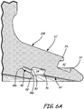
- FIGS. 5 , 6A and 6B Another exemplary boss, which is not according to the invention, is illustrated in FIGS. 5 , 6A and 6B .
- This exemplary boss 16B construction is similar to that of boss 16A, discussed above, except that no groove is provided radially inwardly of the inner keyway 44.
- a plurality of discrete bores 48 are provided in the boss 16B in a near radial direction, via openings 48a in sidewall 50 of the keyway 44.
- a "bore" need not extend all the way through a member.
- the bore 48 may extend from its openings 48a to a closed end thereof, as at 48c in FIGS. 6A and 6B .
Description
- Pressure vessels are commonly used for containing a variety of fluids under pressure, such as storing oxygen, natural gas, nitrogen, propane and other fuels, for example. Suitable container materials include laminated layers of wound fiberglass filaments or other synthetic filaments bonded together by a thermal-setting or thermoplastic resin. An elastomeric or other non-metal resilient liner or bladder often is disposed within the composite shell to seal the vessel and prevent internal fluids from contacting the composite material. The composite construction of the vessels provides numerous advantages such as lightness in weight and resistance to corrosion, fatigue and catastrophic failure. These attributes are due to the high specific strengths of the reinforcing fibers or filaments that are typically oriented in the direction of the principal forces in the construction of the pressure vessels.
-
FIGS. 1 and 2 illustrate anelongated pressure vessel 10, such as that disclosed inU.S. Patent No. 5,476,189 . Vessel 10 has amain body section 12 withend sections 14. Aboss 16 is provided at one or both ends of thevessel 10 to provide a port for communicating with the interior of thevessel 10. Thevessel 10 is formed from aninner polymer liner 20 covered by anouter composite shell 18. In this case, "composite" means a fiber reinforced resin matrix material, such as a filament wound or laminated structure. - The
liner 20 has a generallyhemispheroidal end section 22 with anopening 24 aligned within an opening 26 in theouter composite shell 18. Boss 16 is positioned within the aligned openings and includes aneck portion 28 and a radially outwardly projectingflange portion 30. Theboss 16 defines aport 32 through which fluid at high pressure may be communicated with the interior of thepressure vessel 10. -
Liner 20 includes a dual layer lipcircumscribing opening 24 in theliner 20, with anouter lip segment 34 and aninner lip segment 36 defining anannular recess 38 therebetween for receivingflange portion 30 ofboss 16. Dovetailed inter-engaging locking means 40 are provided betweenflange portion 30 and outer andinner lip segments liner 20 toboss 16. DocumentUS 2007 / 0164561 discloses another boss for a pressure vessel. - This type of interlocking liner and boss structure has proved effective in certain applications, such as for compressed natural gas (CNG) fuel containers. However, in high pressure (e.g., 700 bar) service, distortions of the plastic liner material adjacent the boss has been noted, leading to some tendency of the plastic to be pulled out of the keyway (i.e., out of the interlocking means 40). The "distortion" of this area in high pressure applications comes from the presence of high pressure gas in the keyway between the
liner 20 andboss 16. High pressure gas saturates the liner material and then outgases when the pressure drops. Thus, the gas permeating the area between theliner 20 andboss 16 can then have a higher pressure than the gas withinvessel 10, such as, for example, when gas is being vented from thevessel 10. As a result, the excess pressure between theliner 20 andboss 16 can cause the liner material to be forced out of the keyway. Thus, there remains a need for a liner and boss interface structure that prevents separation of the liner and boss under high pressure and that allows venting of any such gas trapped in the keyway between the liner and the boss. - The invention is according to the appended claim set. According to the invention, the disclosure describes a boss for a pressure vessel, the boss having a flange. The flange comprises an interior keyway having an inner sidewall and a plurality of bores disposed on the inner sidewall.
- Not according to the present invention, the disclosure describes a pressure vessel comprising a main body section and an end section connected to the main body. The end section comprises a boss and the boss comprises a flange. The flange comprises an interior keyway having an inner sidewall and a plurality of bores disposed on the inner sidewall.
- Not according to the present invention, the disclosure describes a pressure vessel comprising a composite shell and a boss. The composite shell comprises an outer shell and an inner liner disposed within the outer shell. The boss defines a port in the composite shell and comprises a flange with an exterior side and an interior side. The liner is mechanically integrated with the flange via a plurality of anchors, each anchor contacting the flange only on the interior side thereof.
- In another aspect according to the invention, the disclosure describes a method of forming a pressure vessel comprises providing a boss having a flange. The flange has an interior keyway having an inner sidewall and a plurality of bores disposed on the inner sidewall. The method comprises allowing a fluid polymer material to flow into the interior keyway and into the plurality of bores.
- This summary is provided to introduce concepts in simplified form that are further described below in the Detailed Description. This summary is not intended to identify key features or essential features of the disclosed or claimed subject matter and is not intended to describe each disclosed embodiment or every implementation of the disclosed or claimed subject matter. Specifically, features disclosed herein with respect to one embodiment may be equally applicable to another. Further, this summary is not intended to be used as an aid in determining the scope of the claimed subject matter. Many other novel advantages, features, and relationships will become apparent as this description proceeds. The figures and the description that follow more particularly exemplify illustrative embodiments.
- The disclosed subject matter will be further explained with reference to the attached figures, wherein like structure or system elements are referred to by like reference numerals throughout the several views.
-
FIG. 1 is a side elevation view of a typical elongated pressure vessel. -
FIG. 2 is a partial cross-sectional view through one end of such a pressure vessel, taken along line 2-2 ofFIG. 1 . -
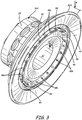
FIG. 3 is a perspective view of one embodiment of a boss of the present disclosure according to the invention. -
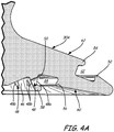
FIG. 4A is a partial cross-sectional view through the boss ofFIG. 3 , taken along line 4-4. -
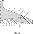
FIG. 4B is similar toFIG. 4A but shows the boss connected to a vessel liner. -
FIG. 5 is a perspective view of one embodiment of a boss, which is not according to the present invention. -
FIG. 6A is a partial cross-sectional view through the boss ofFIG. 5 , taken along line 6-6 and is not according to the present invention. -
FIG. 6B is similar toFIG. 6A but shows the boss connected to a vessel liner. It is not according to the present invention. - While the above-identified figures set forth one or more embodiments of the disclosed subject matter, other embodiments are also contemplated, as noted in the disclosure. In all cases, this disclosure presents the disclosed subject matter by way of representation and not limitation. It should be understood that numerous other modifications and embodiments can be devised by those skilled in the art.
- The figures may not be drawn to scale. Moreover, where terms such as above, below, over, under, top, bottom, side, right, left, etc., are used, it is to be understood that they are used only for ease of understanding the description. It is contemplated that structures may be otherwise oriented.
- In one embodiment, an improved boss and liner interface structure is illustrated on
boss 16A ofFIGS. 3 ,4A and4B . Annular external orexterior keyway 42 and annular internal orinterior keyway 44 are provided onflange 30 to mate with interlockingkeys liner 20, respectively. As used in this disclosure, the term "dovetail" describes a keyway or interlocking key configuration comprising a lip, notch, flare, projection or similar or corresponding structure so that a joint formed between thekeyway 42/44 ofboss 16A and interlockingkeys 42a/44a ofliner 20 is structurally inhibited from separation.External keyway 42 includesannular lip 52 extending in an axial direction to prevent separation in the radial direction andannular lip 54 extending in a radial direction to prevent separation in the axial direction. Similarly,internal keyway 44 includesannular lip 56 extending in an axial direction to prevent separation in the radial direction andannular lip 58 extending in a radial direction to prevent separation in the axial direction. - An
annular groove 46 is defined on an interior side offlange 30A ofboss 16A, radially inwardly ofinternal keyway 44.Groove 46 is connected tointernal keyway 44 by means of a plurality ofdiscrete bores 48 formed betweeninner sidewall 50 ofinternal keyway 44 andgroove 46, with each bore 48 having, at one end thereof, afirst opening 48a ininternal keyway 44 and, at a second end thereof, a second opening ingroove 46. In cross-section, bores 48 may be circular or elongated, for example. In an exemplary embodiment,groove 46 is substantially "V"-shaped. - A method of forming a
pressure vessel 10 includes allowing a fluid polymer material forliner 20 to flow into and fill the external keyway, 42,internal keyway 44,groove 46 and bores 48. The liner material then solidifies, thereby forming key 42a, key 44a andanchor 49.Liner 20 is mechanically interlocked withboss 16A byanchors 49 formed withinbores 48, connecting the liner material ingroove 46 with the liner material in internal keyway 44 (key 44a). Accordingly, even under extreme pressure conditions, separation ofliner 20 fromboss 16A is prevented. In effect, theliner material 20 would need to tear apart before separation ofliner 20 andboss 16A could occur. -
Flange 30A has aninterior side 60 and anexterior side 62. In an exemplary embodiment, eachanchor 49 contacts only the interior side of theflange 30A, and does not contact the exterior side of theflange 30A. Becauseinternal keyway 44,groove 46 and bores 48 are all located on theinterior side 60 offlange 30A, there is no passage for gas leakage from the interior side offlange 30A to the exterior side offlange 30A. Moreover, any built-up gas betweenliner 20 andboss 16A can escape back intovessel 10 at opening 24 of liner 20 (seeFIG. 2 ), thereby preventing a rupture or separation at the interface ofliner 20 andboss 16A. - Another exemplary boss, which is not according to the invention, is illustrated in
FIGS. 5 ,6A and6B . Thisexemplary boss 16B construction is similar to that ofboss 16A, discussed above, except that no groove is provided radially inwardly of theinner keyway 44. Within thatinner keyway 44, a plurality ofdiscrete bores 48 are provided in theboss 16B in a near radial direction, viaopenings 48a insidewall 50 of thekeyway 44. As used herein, a "bore" need not extend all the way through a member. As such, thebore 48 may extend from itsopenings 48a to a closed end thereof, as at 48c inFIGS. 6A and6B . Asvessel 10 is formed, the material ofliner 20 again forms annular keys that flow into and interlock withannular keyways 42 and 44 (external key 42b and internal key 44b, respectively). From internal key 44b, liner material fills bores 48 to formanchors 49 for preventing the separation ofboss 16B andliner 20. - Each of the boss constructions discussed above (the
boss 16A illustrated inFIGS. 3 ,4A and4B and theboss 16B illustrated inFIGS. 5 ,6A and6B ) is intended to provide a highly stable and integrated interface between theboss 16A/B andliner 20, in order to prevent blowout and/or gas buildup between theboss 16A/B andliner 20. - Although the subject of this disclosure has been described with reference to one embodiment, workers skilled in the art will recognize that changes may be made in form and detail. In addition, some features disclosed with respect to one embodiment may be incorporated in another embodiment, and vice-versa. For example, some bores may extend all the way through a portion of the flange (such as shown, for example, in
FIGS. 3 ,4A and4B , according to the invention) while others do not (such as shown, for example, inFIGS. 5 ,6A and6B , not according to the present invention). Bore configurations may alternate radially around the flange (all-the-way-through bore, closed-end bore, all-the-way-through bore, etc.) or may be arranged in any other intermingled bore configuration arrangement about the flange.
Claims (12)
- A boss (16A) for a pressure vessel (10), the boss (16A) having a flange (30A) having an exterior side (62) and an interior side (60), the boss (16A) comprising an interior keyway (44) disposed on the interior side (60) and having an inner sidewall (50), wherein there is no passage for gas leakage from the interior side of the flange (30A) to the exterior side of the flange (30A), the boss (16A) characterized by:a groove (46) on the interior side (60) disposed radially inward of the interior keyway (44); anda plurality of bores (48) on the interior side (60) disposed on the inner sidewall (50) and connecting the interior keyway (44) and the groove (46).
- The boss (16A) of claim 1 wherein the groove (46) is "V"-shaped.
- The boss (16A) of claim 1 wherein the interior keyway (44) comprises a lip (56) extending in an axial direction.
- The boss (16A) of claim 1 wherein the interior keyway (44) comprises a lip (58) extending in a radial direction.
- The boss (16A) of claim 1 further comprising an exterior keyway (42) disposed on the exterior side (62).
- The boss (16A) of claim 6 wherein the exterior keyway (42) comprises a lip (52) extending in an axial direction.
- The boss (16A) of claim 6 wherein the exterior keyway (42) comprises a lip (54) extending in a radial direction.
- The boss (16A) of claim 1 wherein each bore (48) has a first opening (48a) for that bore (48) extending into the flange (30A) of the boss (16A).
- The boss (16A) of claim 1 wherein at least one bore (48) extends through a portion of the flange (30A) to a second opening (48b) for that bore (48) on the interior side (60) of the flange (30A).
- The boss (16A) of claim 9 wherein each second opening (48b) is disposed in an annular groove (46) on the interior side (60) of the flange (30A).
- The boss (16A) of claim 9 wherein each bore (48) extends through the portion of the flange (30A) to the second opening (48b) for that bore (48) on the interior side (60) of the flange (30A).
- A method of forming a pressure vessel (10) characterized by the method comprising:providing a boss (16A) having a flange (30A) having an exterior side (62) and an interior side (60), the boss (16A) comprising:an interior keyway (44) disposed on the interior side (60) and having an inner sidewall (50);a groove (46) on the interior side (60) disposed radially inward of the interior keyway (44); anda plurality of bores (48) on the interior side (60) disposed on the inner sidewall (50) and connecting the interior keyway (44) and the groove (46);wherein there is no passage for gas leakage from the interior side of the flange (30A) to the exterior side of the flange (30A);allowing a fluid polymer material (20) to flow into the interior keyway (44), into the groove (46), and into the plurality of bores (48);solidifying the fluid polymer material (20) to form a liner (20) of the pressure vessel (10); andforming a shell (18) surrounding the liner (20).
Applications Claiming Priority (2)
| Application Number | Priority Date | Filing Date | Title |
|---|---|---|---|
| US14351609P | 2009-01-09 | 2009-01-09 | |
| PCT/US2010/020425 WO2010080948A1 (en) | 2009-01-09 | 2010-01-08 | Pressure vessel boss and liner interface |
Publications (2)
| Publication Number | Publication Date |
|---|---|
| EP2384408A1 EP2384408A1 (en) | 2011-11-09 |
| EP2384408B1 true EP2384408B1 (en) | 2019-03-13 |
Family
ID=41664872
Family Applications (1)
| Application Number | Title | Priority Date | Filing Date |
|---|---|---|---|
| EP10700091.1A Active EP2384408B1 (en) | 2009-01-09 | 2010-01-08 | Pressure vessel boss and liner interface |
Country Status (10)
| Country | Link |
|---|---|
| US (3) | US9103500B2 (en) |
| EP (1) | EP2384408B1 (en) |
| JP (1) | JP5587339B2 (en) |
| KR (1) | KR101498277B1 (en) |
| CN (1) | CN102282409B (en) |
| AU (1) | AU2010203557B2 (en) |
| BR (1) | BRPI1006059B1 (en) |
| CA (1) | CA2749311C (en) |
| RU (1) | RU2511881C2 (en) |
| WO (1) | WO2010080948A1 (en) |
Cited By (1)
| Publication number | Priority date | Publication date | Assignee | Title |
|---|---|---|---|---|
| US11174990B2 (en) | 2017-12-27 | 2021-11-16 | Toyota Jidosha Kabushiki Kaisha | Tank |
Families Citing this family (37)
| Publication number | Priority date | Publication date | Assignee | Title |
|---|---|---|---|---|
| GB2485533B (en) * | 2010-11-15 | 2014-02-12 | Roger Carr | Vessel with associated collar |
| KR101221004B1 (en) * | 2011-01-19 | 2013-01-10 | 주식회사 일진유니스코 | Nozzle-boss for high pressure vessel |
| DE102011111406A1 (en) * | 2011-08-30 | 2013-02-28 | Amir R. Shubbar | Pressure tank with plug-in and welded connection for the connection piece |
| US8733581B1 (en) | 2012-07-16 | 2014-05-27 | Michael A. Olson | Boss seal for composite overwrapped pressure vessel |
| EP2929231A1 (en) * | 2012-12-05 | 2015-10-14 | Blue Wave Co S.A. | Pressure vessel having composite boss with weldable metal fitting |
| US20150338024A1 (en) | 2013-01-07 | 2015-11-26 | Fibrasynthetica Do Brasil Ltda. | Nozzle for a plastic container and plastic container for pressurized gases |
| JP5979446B2 (en) * | 2013-02-04 | 2016-08-24 | 豊田合成株式会社 | Pressure vessel |
| TR201302927A2 (en) * | 2013-03-11 | 2014-09-22 | Tofas Tuerk Otomobil Fabrikasi Anonim Sirketi | Boss structure |
| JP5936642B2 (en) * | 2013-04-17 | 2016-06-22 | 豊田合成株式会社 | Pressure vessel liner, mold thereof, and pressure vessel |
| JP6264244B2 (en) * | 2014-09-17 | 2018-01-24 | トヨタ自動車株式会社 | High pressure tank |
| DE102015105901A1 (en) | 2015-04-17 | 2016-10-20 | xperion Energy & Environment GmbH | Pressure vessel and method of manufacture |
| JP6582563B2 (en) * | 2015-06-02 | 2019-10-02 | 横浜ゴム株式会社 | Aircraft water tank |
| US10317009B2 (en) | 2015-08-06 | 2019-06-11 | Toyota Jidosha Kabushiki Kaisha | High pressure tank, manufacturing method of high pressure tank, and inspection method of sealing characteristic |
| US10408383B2 (en) * | 2015-10-30 | 2019-09-10 | Carleton Technologies, Inc. | Boss and seal for a high-pressure vessel |
| US10627048B2 (en) * | 2015-12-16 | 2020-04-21 | Hexagon Technology, As | Pressure vessel dome vents |
| BR112018068161B1 (en) * | 2016-03-07 | 2023-04-04 | Hexagon Technology As | ASSEMBLY INCLUDING A PRESSURE VESSEL, APPARATUS CONFIGURED TO PREVENT DAMAGE TO A PRESSURE VESSEL AND METHOD FOR ATTACHING A COMPONENT TO A PRESSURE VESSEL |
| JP6575414B2 (en) | 2016-03-29 | 2019-09-18 | 豊田合成株式会社 | Pressure vessel |
| US10544901B2 (en) * | 2016-04-06 | 2020-01-28 | Hexagon Technology As | Pressure vessel vented boss with sintered metal plug |
| KR102463415B1 (en) * | 2016-12-20 | 2022-11-03 | 현대자동차주식회사 | High pressure tank having reinforced boss-part |
| DE102016125866A1 (en) * | 2016-12-29 | 2018-07-05 | Abdul Amir Shubbar | Improved antistatic pressure tank |
| CN106838602B (en) * | 2017-01-19 | 2023-04-18 | 安徽绿动能源有限公司 | Metal bottle mouth structure and LPG gas cylinder |
| CN106870932A (en) * | 2017-02-17 | 2017-06-20 | 安徽绿动能源有限公司 | A kind of metal bottleneck structure and composite cylinder |
| US10746354B2 (en) * | 2017-05-24 | 2020-08-18 | Hexagon Technology, As | Threaded boss for pressure vessel |
| JP7124450B2 (en) * | 2018-05-29 | 2022-08-24 | トヨタ自動車株式会社 | high pressure gas tank |
| CN109132246B (en) * | 2018-08-30 | 2023-07-04 | 浙江科赛新材料科技有限公司 | Oil tank joint |
| DE102018009829B4 (en) * | 2018-12-14 | 2020-09-17 | Emano Kunststofftechnik Gmbh | Pressure vessel and method of manufacturing the pressure vessel |
| US11440399B2 (en) | 2019-03-22 | 2022-09-13 | Agility Fuel Systems Llc | Fuel system mountable to a vehicle frame |
| US20200347992A1 (en) | 2019-05-02 | 2020-11-05 | Agility Fuel Systems Llc | Polymeric liner based gas cylinder with reduced permeability |
| JP6870027B2 (en) * | 2019-05-16 | 2021-05-12 | 本田技研工業株式会社 | High-pressure tank and its manufacturing method |
| US20220373085A1 (en) | 2019-06-28 | 2022-11-24 | Linamar Corporation | End boss for type iv pressure vessel |
| DE102020001135B3 (en) * | 2020-02-20 | 2021-08-26 | Emano Kunststofftechnik Gmbh | Pressure vessel and method of making a pressure vessel |
| KR102442629B1 (en) * | 2020-09-28 | 2022-09-14 | 한화솔루션 주식회사 | High-pressure tank having sealing structure boss and making method thereof |
| CN112393112B (en) * | 2020-12-08 | 2022-08-09 | 亚普汽车部件股份有限公司 | Bottleneck seal structure and high-pressure composite container |
| KR102460148B1 (en) | 2021-01-04 | 2022-11-01 | 주식회사 성우하이텍 | pressure vessel |
| FR3121968B1 (en) * | 2021-04-16 | 2023-12-08 | Faurecia Systemes Dechappement | Tank for pressurized gas |
| CN113548327A (en) * | 2021-07-09 | 2021-10-26 | 苏州方林科技股份有限公司 | Nested injection molding water nozzle structure and processing method thereof |
| DE102022002415B4 (en) * | 2022-07-04 | 2024-02-22 | Emano Kunststofftechnik Gmbh | pressure vessel |
Family Cites Families (24)
| Publication number | Priority date | Publication date | Assignee | Title |
|---|---|---|---|---|
| US4589563A (en) | 1983-03-07 | 1986-05-20 | Quality Products, Inc. | High-pressure container and method of making the same |
| DE69206114T2 (en) | 1992-01-10 | 1996-04-18 | Technical Products Group Inc | Pole piece for a fiber-wound pressure vessel. |
| KR100204179B1 (en) * | 1992-01-10 | 1999-06-15 | 마이클디,슈미츠 | Interance hall of pressure vessel |
| US5429845A (en) | 1992-01-10 | 1995-07-04 | Brunswick Corporation | Boss for a filament wound pressure vessel |
| US5494188A (en) | 1992-01-28 | 1996-02-27 | Edo Canada Ltd. | Fluid pressure vessel boss-liner attachment system with liner/exterior mechanism direct coupling |
| US5287988A (en) * | 1993-02-03 | 1994-02-22 | Brunswick Corporation | Metal-lined pressure vessel |
| US5476189A (en) * | 1993-12-03 | 1995-12-19 | Duvall; Paul F. | Pressure vessel with damage mitigating system |
| US5518141A (en) | 1994-01-24 | 1996-05-21 | Newhouse; Norman L. | Pressure vessel with system to prevent liner separation |
| BR9600459A (en) * | 1996-01-17 | 1998-03-03 | Fibrasynthetica Do Brasil Comp | Plastic container for pressurized fluids |
| US5938209A (en) * | 1997-02-14 | 1999-08-17 | Alternative Fuel Systems, Inc. | Seal system for fluid pressure vessels |
| US5819978A (en) * | 1997-04-24 | 1998-10-13 | Essef Corporation | Two piece composite inlet |
| JPH1144399A (en) | 1997-05-27 | 1999-02-16 | Mitsubishi Chem Corp | Pressure vessel |
| JPH10332083A (en) * | 1997-05-28 | 1998-12-15 | Mitsubishi Chem Corp | Pressure-resisting container |
| US6793095B1 (en) | 1998-02-04 | 2004-09-21 | Essef Corporation | Blow-molded pressure tank with spin-welded connector |
| US5979692A (en) | 1998-03-13 | 1999-11-09 | Harsco Corporation | Boss for composite pressure vessel having polymeric liner |
| US6135308A (en) | 1998-06-26 | 2000-10-24 | Industrial Technology Research Institute | Boss for a filament wound pressure vessel |
| JP3523802B2 (en) * | 1999-04-07 | 2004-04-26 | 豊田合成株式会社 | Pressure vessel |
| US6386384B1 (en) * | 2000-02-09 | 2002-05-14 | Amtrol, Inc. | Full jacket gas cylinder |
| RU2188356C2 (en) * | 2000-11-10 | 2002-08-27 | Пермский государственный технический университет | High-pressure composite gas bottle |
| DE10360953B4 (en) * | 2002-12-27 | 2011-04-07 | Toyoda Gosei Co., Ltd., Nishikasugai-gun | pressure vessel |
| KR100469636B1 (en) * | 2004-03-11 | 2005-02-02 | 주식회사 케이시알 | The high gas-tighten metallic nozzle-boss for the high pressure composite vessel |
| JP4457359B2 (en) * | 2006-12-13 | 2010-04-28 | トヨタ自動車株式会社 | Pressure vessel |
| JP4392804B2 (en) | 2007-04-06 | 2010-01-06 | 豊田合成株式会社 | Pressure vessel |
| US8668108B2 (en) * | 2009-02-18 | 2014-03-11 | Brian Yeggy | Pressure vessel shear resistant boss and shell interface element |
-
2010
- 2010-01-08 JP JP2011545439A patent/JP5587339B2/en active Active
- 2010-01-08 AU AU2010203557A patent/AU2010203557B2/en not_active Ceased
- 2010-01-08 WO PCT/US2010/020425 patent/WO2010080948A1/en active Application Filing
- 2010-01-08 CA CA2749311A patent/CA2749311C/en active Active
- 2010-01-08 US US13/143,250 patent/US9103500B2/en active Active
- 2010-01-08 KR KR1020117017924A patent/KR101498277B1/en active IP Right Grant
- 2010-01-08 CN CN201080004144.4A patent/CN102282409B/en active Active
- 2010-01-08 BR BRPI1006059-6A patent/BRPI1006059B1/en active IP Right Grant
- 2010-01-08 EP EP10700091.1A patent/EP2384408B1/en active Active
- 2010-01-08 RU RU2011133220/06A patent/RU2511881C2/en active
-
2015
- 2015-08-07 US US14/820,692 patent/US9644790B2/en active Active
-
2017
- 2017-04-04 US US15/478,610 patent/US10180210B2/en active Active
Non-Patent Citations (1)
| Title |
|---|
| None * |
Cited By (2)
| Publication number | Priority date | Publication date | Assignee | Title |
|---|---|---|---|---|
| US11174990B2 (en) | 2017-12-27 | 2021-11-16 | Toyota Jidosha Kabushiki Kaisha | Tank |
| DE102018129757B4 (en) | 2017-12-27 | 2022-01-20 | Toyota Jidosha Kabushiki Kaisha | TANK |
Also Published As
| Publication number | Publication date |
|---|---|
| US9644790B2 (en) | 2017-05-09 |
| CN102282409B (en) | 2016-03-23 |
| US20150345702A1 (en) | 2015-12-03 |
| RU2011133220A (en) | 2013-02-20 |
| AU2010203557B2 (en) | 2014-05-29 |
| BRPI1006059A2 (en) | 2018-04-24 |
| US9103500B2 (en) | 2015-08-11 |
| BRPI1006059B1 (en) | 2020-06-23 |
| WO2010080948A1 (en) | 2010-07-15 |
| RU2511881C2 (en) | 2014-04-10 |
| EP2384408A1 (en) | 2011-11-09 |
| US10180210B2 (en) | 2019-01-15 |
| JP5587339B2 (en) | 2014-09-10 |
| CN102282409A (en) | 2011-12-14 |
| US20170205029A1 (en) | 2017-07-20 |
| KR101498277B1 (en) | 2015-03-02 |
| JP2012514727A (en) | 2012-06-28 |
| CA2749311C (en) | 2015-03-24 |
| US20110303681A1 (en) | 2011-12-15 |
| AU2010203557A1 (en) | 2011-07-14 |
| CA2749311A1 (en) | 2010-07-15 |
| KR20110105851A (en) | 2011-09-27 |
Similar Documents
| Publication | Publication Date | Title |
|---|---|---|
| EP2384408B1 (en) | Pressure vessel boss and liner interface | |
| US11073240B2 (en) | Pressure vessel dome vents | |
| US8668108B2 (en) | Pressure vessel shear resistant boss and shell interface element | |
| US20200332957A1 (en) | Threaded boss for pressure vessel | |
| EP3458768B1 (en) | Pressure vessel liner venting via nanotextured surface | |
| US11441732B2 (en) | Manufacturing method for high-pressure tank and high-pressure tank |
Legal Events
| Date | Code | Title | Description |
|---|---|---|---|
| PUAI | Public reference made under article 153(3) epc to a published international application that has entered the european phase |
Free format text: ORIGINAL CODE: 0009012 |
|
| 17P | Request for examination filed |
Effective date: 20110801 |
|
| AK | Designated contracting states |
Kind code of ref document: A1 Designated state(s): AT BE BG CH CY CZ DE DK EE ES FI FR GB GR HR HU IE IS IT LI LT LU LV MC MK MT NL NO PL PT RO SE SI SK SM TR |
|
| DAX | Request for extension of the european patent (deleted) | ||
| 17Q | First examination report despatched |
Effective date: 20120502 |
|
| STAA | Information on the status of an ep patent application or granted ep patent |
Free format text: STATUS: EXAMINATION IS IN PROGRESS |
|
| GRAP | Despatch of communication of intention to grant a patent |
Free format text: ORIGINAL CODE: EPIDOSNIGR1 |
|
| STAA | Information on the status of an ep patent application or granted ep patent |
Free format text: STATUS: GRANT OF PATENT IS INTENDED |
|
| INTG | Intention to grant announced |
Effective date: 20181031 |
|
| GRAS | Grant fee paid |
Free format text: ORIGINAL CODE: EPIDOSNIGR3 |
|
| GRAA | (expected) grant |
Free format text: ORIGINAL CODE: 0009210 |
|
| STAA | Information on the status of an ep patent application or granted ep patent |
Free format text: STATUS: THE PATENT HAS BEEN GRANTED |
|
| AK | Designated contracting states |
Kind code of ref document: B1 Designated state(s): AT BE BG CH CY CZ DE DK EE ES FI FR GB GR HR HU IE IS IT LI LT LU LV MC MK MT NL NO PL PT RO SE SI SK SM TR |
|
| REG | Reference to a national code |
Ref country code: GB Ref legal event code: FG4D |
|
| REG | Reference to a national code |
Ref country code: CH Ref legal event code: EP Ref country code: AT Ref legal event code: REF Ref document number: 1108185 Country of ref document: AT Kind code of ref document: T Effective date: 20190315 |
|
| REG | Reference to a national code |
Ref country code: IE Ref legal event code: FG4D |
|
| REG | Reference to a national code |
Ref country code: DE Ref legal event code: R096 Ref document number: 602010057512 Country of ref document: DE |
|
| REG | Reference to a national code |
Ref country code: NL Ref legal event code: MP Effective date: 20190313 |
|
| REG | Reference to a national code |
Ref country code: LT Ref legal event code: MG4D |
|
| PG25 | Lapsed in a contracting state [announced via postgrant information from national office to epo] |
Ref country code: LT Free format text: LAPSE BECAUSE OF FAILURE TO SUBMIT A TRANSLATION OF THE DESCRIPTION OR TO PAY THE FEE WITHIN THE PRESCRIBED TIME-LIMIT Effective date: 20190313 Ref country code: SE Free format text: LAPSE BECAUSE OF FAILURE TO SUBMIT A TRANSLATION OF THE DESCRIPTION OR TO PAY THE FEE WITHIN THE PRESCRIBED TIME-LIMIT Effective date: 20190313 Ref country code: FI Free format text: LAPSE BECAUSE OF FAILURE TO SUBMIT A TRANSLATION OF THE DESCRIPTION OR TO PAY THE FEE WITHIN THE PRESCRIBED TIME-LIMIT Effective date: 20190313 |
|
| REG | Reference to a national code |
Ref country code: NO Ref legal event code: T2 Effective date: 20190313 |
|
| PG25 | Lapsed in a contracting state [announced via postgrant information from national office to epo] |
Ref country code: HR Free format text: LAPSE BECAUSE OF FAILURE TO SUBMIT A TRANSLATION OF THE DESCRIPTION OR TO PAY THE FEE WITHIN THE PRESCRIBED TIME-LIMIT Effective date: 20190313 Ref country code: GR Free format text: LAPSE BECAUSE OF FAILURE TO SUBMIT A TRANSLATION OF THE DESCRIPTION OR TO PAY THE FEE WITHIN THE PRESCRIBED TIME-LIMIT Effective date: 20190614 Ref country code: LV Free format text: LAPSE BECAUSE OF FAILURE TO SUBMIT A TRANSLATION OF THE DESCRIPTION OR TO PAY THE FEE WITHIN THE PRESCRIBED TIME-LIMIT Effective date: 20190313 Ref country code: BG Free format text: LAPSE BECAUSE OF FAILURE TO SUBMIT A TRANSLATION OF THE DESCRIPTION OR TO PAY THE FEE WITHIN THE PRESCRIBED TIME-LIMIT Effective date: 20190613 Ref country code: NL Free format text: LAPSE BECAUSE OF FAILURE TO SUBMIT A TRANSLATION OF THE DESCRIPTION OR TO PAY THE FEE WITHIN THE PRESCRIBED TIME-LIMIT Effective date: 20190313 |
|
| REG | Reference to a national code |
Ref country code: AT Ref legal event code: MK05 Ref document number: 1108185 Country of ref document: AT Kind code of ref document: T Effective date: 20190313 |
|
| PG25 | Lapsed in a contracting state [announced via postgrant information from national office to epo] |
Ref country code: SK Free format text: LAPSE BECAUSE OF FAILURE TO SUBMIT A TRANSLATION OF THE DESCRIPTION OR TO PAY THE FEE WITHIN THE PRESCRIBED TIME-LIMIT Effective date: 20190313 Ref country code: PT Free format text: LAPSE BECAUSE OF FAILURE TO SUBMIT A TRANSLATION OF THE DESCRIPTION OR TO PAY THE FEE WITHIN THE PRESCRIBED TIME-LIMIT Effective date: 20190713 Ref country code: ES Free format text: LAPSE BECAUSE OF FAILURE TO SUBMIT A TRANSLATION OF THE DESCRIPTION OR TO PAY THE FEE WITHIN THE PRESCRIBED TIME-LIMIT Effective date: 20190313 Ref country code: CZ Free format text: LAPSE BECAUSE OF FAILURE TO SUBMIT A TRANSLATION OF THE DESCRIPTION OR TO PAY THE FEE WITHIN THE PRESCRIBED TIME-LIMIT Effective date: 20190313 Ref country code: RO Free format text: LAPSE BECAUSE OF FAILURE TO SUBMIT A TRANSLATION OF THE DESCRIPTION OR TO PAY THE FEE WITHIN THE PRESCRIBED TIME-LIMIT Effective date: 20190313 Ref country code: EE Free format text: LAPSE BECAUSE OF FAILURE TO SUBMIT A TRANSLATION OF THE DESCRIPTION OR TO PAY THE FEE WITHIN THE PRESCRIBED TIME-LIMIT Effective date: 20190313 |
|
| PG25 | Lapsed in a contracting state [announced via postgrant information from national office to epo] |
Ref country code: PL Free format text: LAPSE BECAUSE OF FAILURE TO SUBMIT A TRANSLATION OF THE DESCRIPTION OR TO PAY THE FEE WITHIN THE PRESCRIBED TIME-LIMIT Effective date: 20190313 Ref country code: SM Free format text: LAPSE BECAUSE OF FAILURE TO SUBMIT A TRANSLATION OF THE DESCRIPTION OR TO PAY THE FEE WITHIN THE PRESCRIBED TIME-LIMIT Effective date: 20190313 |
|
| REG | Reference to a national code |
Ref country code: DE Ref legal event code: R097 Ref document number: 602010057512 Country of ref document: DE |
|
| PG25 | Lapsed in a contracting state [announced via postgrant information from national office to epo] |
Ref country code: IS Free format text: LAPSE BECAUSE OF FAILURE TO SUBMIT A TRANSLATION OF THE DESCRIPTION OR TO PAY THE FEE WITHIN THE PRESCRIBED TIME-LIMIT Effective date: 20190713 Ref country code: AT Free format text: LAPSE BECAUSE OF FAILURE TO SUBMIT A TRANSLATION OF THE DESCRIPTION OR TO PAY THE FEE WITHIN THE PRESCRIBED TIME-LIMIT Effective date: 20190313 |
|
| PLBE | No opposition filed within time limit |
Free format text: ORIGINAL CODE: 0009261 |
|
| STAA | Information on the status of an ep patent application or granted ep patent |
Free format text: STATUS: NO OPPOSITION FILED WITHIN TIME LIMIT |
|
| PG25 | Lapsed in a contracting state [announced via postgrant information from national office to epo] |
Ref country code: DK Free format text: LAPSE BECAUSE OF FAILURE TO SUBMIT A TRANSLATION OF THE DESCRIPTION OR TO PAY THE FEE WITHIN THE PRESCRIBED TIME-LIMIT Effective date: 20190313 |
|
| 26N | No opposition filed |
Effective date: 20191216 |
|
| PG25 | Lapsed in a contracting state [announced via postgrant information from national office to epo] |
Ref country code: SI Free format text: LAPSE BECAUSE OF FAILURE TO SUBMIT A TRANSLATION OF THE DESCRIPTION OR TO PAY THE FEE WITHIN THE PRESCRIBED TIME-LIMIT Effective date: 20190313 |
|
| PG25 | Lapsed in a contracting state [announced via postgrant information from national office to epo] |
Ref country code: TR Free format text: LAPSE BECAUSE OF FAILURE TO SUBMIT A TRANSLATION OF THE DESCRIPTION OR TO PAY THE FEE WITHIN THE PRESCRIBED TIME-LIMIT Effective date: 20190313 |
|
| PG25 | Lapsed in a contracting state [announced via postgrant information from national office to epo] |
Ref country code: MC Free format text: LAPSE BECAUSE OF FAILURE TO SUBMIT A TRANSLATION OF THE DESCRIPTION OR TO PAY THE FEE WITHIN THE PRESCRIBED TIME-LIMIT Effective date: 20190313 |
|
| REG | Reference to a national code |
Ref country code: CH Ref legal event code: PL |
|
| REG | Reference to a national code |
Ref country code: BE Ref legal event code: MM Effective date: 20200131 |
|
| PG25 | Lapsed in a contracting state [announced via postgrant information from national office to epo] |
Ref country code: LU Free format text: LAPSE BECAUSE OF NON-PAYMENT OF DUE FEES Effective date: 20200108 |
|
| PG25 | Lapsed in a contracting state [announced via postgrant information from national office to epo] |
Ref country code: LI Free format text: LAPSE BECAUSE OF NON-PAYMENT OF DUE FEES Effective date: 20200131 Ref country code: BE Free format text: LAPSE BECAUSE OF NON-PAYMENT OF DUE FEES Effective date: 20200131 Ref country code: CH Free format text: LAPSE BECAUSE OF NON-PAYMENT OF DUE FEES Effective date: 20200131 |
|
| PG25 | Lapsed in a contracting state [announced via postgrant information from national office to epo] |
Ref country code: IE Free format text: LAPSE BECAUSE OF NON-PAYMENT OF DUE FEES Effective date: 20200108 |
|
| PG25 | Lapsed in a contracting state [announced via postgrant information from national office to epo] |
Ref country code: MT Free format text: LAPSE BECAUSE OF FAILURE TO SUBMIT A TRANSLATION OF THE DESCRIPTION OR TO PAY THE FEE WITHIN THE PRESCRIBED TIME-LIMIT Effective date: 20190313 Ref country code: CY Free format text: LAPSE BECAUSE OF FAILURE TO SUBMIT A TRANSLATION OF THE DESCRIPTION OR TO PAY THE FEE WITHIN THE PRESCRIBED TIME-LIMIT Effective date: 20190313 |
|
| PG25 | Lapsed in a contracting state [announced via postgrant information from national office to epo] |
Ref country code: MK Free format text: LAPSE BECAUSE OF FAILURE TO SUBMIT A TRANSLATION OF THE DESCRIPTION OR TO PAY THE FEE WITHIN THE PRESCRIBED TIME-LIMIT Effective date: 20190313 |
|
| PGFP | Annual fee paid to national office [announced via postgrant information from national office to epo] |
Ref country code: NO Payment date: 20230127 Year of fee payment: 14 Ref country code: FR Payment date: 20230125 Year of fee payment: 14 |
|
| PGFP | Annual fee paid to national office [announced via postgrant information from national office to epo] |
Ref country code: IT Payment date: 20230120 Year of fee payment: 14 Ref country code: GB Payment date: 20230127 Year of fee payment: 14 Ref country code: DE Payment date: 20230127 Year of fee payment: 14 |
|
| P01 | Opt-out of the competence of the unified patent court (upc) registered |
Effective date: 20230518 |