EP2384015A2 - Procédé de marquage de signaux utilisés pour la détection et la mesure de fuite dans des réseaux de télévision par câble et appareil permettant la détection et/ou la mesure de fuite de signaux marqués par un tel procédé - Google Patents
Procédé de marquage de signaux utilisés pour la détection et la mesure de fuite dans des réseaux de télévision par câble et appareil permettant la détection et/ou la mesure de fuite de signaux marqués par un tel procédé Download PDFInfo
- Publication number
- EP2384015A2 EP2384015A2 EP11460021A EP11460021A EP2384015A2 EP 2384015 A2 EP2384015 A2 EP 2384015A2 EP 11460021 A EP11460021 A EP 11460021A EP 11460021 A EP11460021 A EP 11460021A EP 2384015 A2 EP2384015 A2 EP 2384015A2
- Authority
- EP
- European Patent Office
- Prior art keywords
- tagging
- signal
- signals
- leakage
- measurement
- Prior art date
- Legal status (The legal status is an assumption and is not a legal conclusion. Google has not performed a legal analysis and makes no representation as to the accuracy of the status listed.)
- Granted
Links
Images


Classifications
-
- H—ELECTRICITY
- H04—ELECTRIC COMMUNICATION TECHNIQUE
- H04N—PICTORIAL COMMUNICATION, e.g. TELEVISION
- H04N17/00—Diagnosis, testing or measuring for television systems or their details
Definitions
- the present invention relates to a method of tagging signals used for leakage detection and measurement in cable television networks as well as apparatus for the detection and/or measurement of leakage sources tagged with this method.
- Cable television (CATV) systems are commonly used for the transmission and distribution of television and data signals from a headend (a place where the signals are prepared for transmission out onto the cable plant) to end users (subscribers) and for the transmission of data signals (e.g. Internet or telephony) from subscribers to the headend.
- Coaxial cable distribution systems typically use the 5 MHz to 1 GHz spectrum for the transmission of bidirectional analog and digital services. This spectrum shares frequency allocations with conventional broadcasters and many other terrestrial radio communication systems, including trunked radio systems (TETRA or P.25 used, e.g., by police or fire departments) and the air traffic control communication system.
- Signal leakage refers to the transmission of signals through the discontinuities in a coaxial cable distribution network.
- the signals escaping from CATV networks can undesirably interfere with terrestrial radio communication systems, causing dangerous situations (e.g., in civil aviation, emergency services) or problems with signal reception (e.g., interfered terrestrial TV channels).
- each discontinuity radiating the electromagnetic energy from a CATV network forms a receiving antenna through which energy from terrestrial transmitters and other radio frequency sources (so called ingress) can enter the network.
- Most of leakage sources are also ingress sources. Ingress deteriorates the quality of signals propagating in the CATV network, especially from subscribers to the headend (return path services).
- Digital transmissions typical for modern CATV services, are less susceptible to ingress entering the network than analog transmissions. However, a failure in the digital transmission is catastrophic - a subscriber may enjoy the program without any sign of a problem and suddenly experience a complete loss of the service. These are the main reasons of leakage detection and measurement in CATV networks.
- Leakage control is vital for CATV network operators. According to local regulations, they should detect all leakage sources, determine the localization of leakage points, measure their absolute magnitude, and fix the sources which radiate stronger than a specified leakage limit.
- leakage detection devices typically consist of an antenna and a receiver that is tuned to a frequency (referred as a test frequency) in the CATV signal bandwidth.
- a test frequency a frequency in the CATV signal bandwidth.
- Such a device usually has a signal strength (the absolute value of the electric field intensity) measurement circuit.
- a typical method of leakage source detection requires a signal strength measurement on the test frequency. If the signal strength measurement circuit detects a relatively large amplitude signal at a particular location, a leak may be indicated in or near that localization.
- a technician may use a leakage detector to pinpoint the source of a leak. A corrective action may be taken to remove the leak source from the network.
- a drawback of the described leakage detection method lies in its inability to distinguish CATV signals radiated by the system under test from other signals in the same frequency band.
- the detected signal may be radiated from terrestrial transmitters, other radio frequency sources or CATV networks placed in the same area and belonging to other operators.
- U.S. Pat. No. 5,608,428 describes a method in which a low frequency tagging signal is modulated onto an active (in-use) video carrier.
- the method can sometimes cause undesirable signal distortion for analog TV signals.
- the author of the invention claims that it is possible to use the method for digitally modulated signals (like 64-QAM used for digital television and data transmission).
- the power measurement of digitally modulated signal required for establishing the absolute magnitude of the leakage, is more complicated than the power measurement of a sinusoidal wave.
- the measurement bandwidth for leakage should be very narrow (maximum several tenths of kHz around the test frequency - the smaller, the better) in order to reduce interference from other CATV channels or terrestrial radiating sources.
- the CATV digital signal has a bandwidth of a few MHz (8 MHz in Europe and 6 MHz in the U.S.A.), so it is much more susceptible to interfering signals.
- the measurement of the leak magnitude in such a broad bandwidth can give very inaccurate results.
- this method modifies signals transmitted in a CATV network.
- U.S. Pat. Nos. 6,118,975 , 6,307,593 , 6,600,515 and 6,804,826 describe four leakage tagging methods that insert a tagging signal into a television signal only at times at which control information is present (vertical or horizontal synchronization pulses or quiet lines).
- the major drawback of all four methods is the fact that they can be used for tagging of analog television channels only. They also modify some signals transmitted in the network.
- Various parts of the network may belong to or be operated by various operators.
- the main distribution part of a network - from the headend to a particular building - belongs to one operator (O1), and the home wiring inside the building belongs to a building owner (02).
- a leakage source can be localized in the building.
- the mobile leakage patrol organized by O1 can detect this source and coarsely (within a 100-200 m range) determine its localization.
- the precise localization must be found by a technician and requires time and human resources. Due to the financial reasons, the operator O1, who has carried out the mobile patrol, is not interested in finding the precise localization of the leak sources not belonging to his part of the network.
- the standard tagging methods like these described in the U.S.
- Pat. Nos. 4,072,899 , 4,237,486 , 5,608,428 , 6,118,975 , 6,307,593 , 6,600,515 and 6,804,826 do not allow the spatial distinguishing of the CATV network part responsible for a particular detected leak source. They can recognize whether the leak source comes from the network under test, but cannot specify a particular network part where the leak source is localized.
- a leakage tagging method that does not require an out-of-use channel, does not modify the signals transmitted in a CATV network, and can be used for digital television channels (DVB-C, DVB-T or similar systems) and channels used for digital data transmission in the DOCSIS and EuroDOCSIS (or similar) systems.
- the method should also allow an accurate measurement of the absolute leakage magnitude and the determination of the CATV network part (subnetwork) where a detected leakage source is located.
- the method of tagging the signals used for leakage detection and/or measurement in cable television networks using additional signals transmitted in CATV networks and carrying the tagging information is based on placing a narrowband tagging signal (or signals) in certain free parts of the cable television network frequency spectrum, in particular, in the guard bands of digital and/or analog channels.
- the frequency spectrum of the signals transmitted in a particular subnetwork is shaped in each point connecting individual subnetworks in a way that is characteristic of a particular subnetwork and creates a spectrum signature characteristic of each signal radiated from this particular subnetwork.
- the tagging signal is narrowband , with the bandwidth being from a few kHz up to several kHz.
- the apparatus for leakage detection and/or measurements from cable television networks, tagged according to the method presented in the invention, which uses the principle of signal reception based on frequency conversion, has a narrowband filter (or filters) with a bandwidth from a few kHz up to several kHz for the separation of the tagging signals.
- the filter output is connected with the microprocessor input.
- the microprocessor is connected with an antenna switch, a voltage controlled amplifier, a display and a keyboard and has been programmed for sampling and quantizing of the input signal and for the detection of the spectrum components carrying the tagging information.
- the microprocessor uses the fast Fourier transform (FFT) or the discrete cosine transform (DCT) algorithm.
- FFT fast Fourier transform
- DCT discrete cosine transform
- the innovation of the present invention lies in the placement of a tagging signal within the bandwidth formally occupied by a digital or analog signal used for the transmission of services in a CATV network (in-use channels).
- a guard band At both ends of the bandwidth occupied by the signal in a particular CATV channel, there is always a guard band. There is no useful energy (coming from the modulation process) transmitted in this band.
- the main purpose of the guard band is the protection of adjacent channels from interference caused by that particular channel and the simplification of receiver filtering circuits. However, if a narrowband tagging signal are placed in the guard band, the signal in that particular channel and in the adjacent channels will be unaffected.
- Digital data/television channels and analog television channels occupy quite a wide frequency band (6-8 MHz) and are not very susceptible to interference caused by narrowband signals.
- the quality of signals in the adjacent channels will not suffer from the tagging signal due to its being suppressed in the receiver filters.
- any narrowband signal with any type of analog or digital modulation can be used as a tagging signal.
- a tagging signal can be a sinusoidal wave which is modulated with amplitude.
- the modulation frequency is low, in the range from 1 to 50 Hz, in order to minimize the bandwidth occupied by the signal.
- the modulation depth should not exceed 30% in order to minimize the level of the side bands.
- the usage of a sinusoidal wave simplifies the measurement of the absolute magnitude of the leakage by a leakage meter or detector.
- the narrowband tagging signal (not only sinusoidal) in the guard band can be extracted in the leakage meter or detector by means of the fast Fourier transform (FFT), the discrete cosine transform (DCT), or a very narrow bandpass filter, which attenuates the spectrum of the particular channel, the adjacent channels, and interfering signals not lying in the tagging signal band.
- FFT fast Fourier transform
- DCT discrete cosine transform
- the narrowband tagging signal substantially improves the accuracy of leakage magnitude measurements.
- This relationship may be used in leakage meters or detectors to find the leakage level of digital signals which is equivalent to the leakage level of a sinusoidal wave.
- Leakage standards e.g., EN 50083-8 in Europe
- the above described sinusoidal signal with amplitude modulation is one possible form of the tagging signal.
- the present invention finds application in CATV networks with analog and/or digital transmissions.
- the guard band is also present in analog TV (PAL, SECAM or NTSC standards) channels.
- the tagging signal will not affect the picture and the sound quality of analog TV channels. If there is a free channel in a CATV network, it may also be used to place the tagging signal.
- a greater number of tagging signals allows determining the subnetwork where a leakage source lies.
- the minimum number of tagging signals should be equal to two (distinction of the network part belonging to a major operator and to other operators).
- the frequencies of the tagging signals should be placed in the unused parts of the CATV network spectrum (free channels or the guard bands of CATV channels).
- a filter or any passive or active device for example, an amplifier with a proper frequency response, which is able to reduce the level of the tagging signals. It may be a narrow stopband (notch) filter, a bandpass filter, a lowpass filter or a highpass filter depending on the spectrum arrangement and the topology of a CATV network.
- the notch filter can reduce the amplitude of the tagging signal which is assigned to the particular part of a network (a subnetwork).
- a leakage detector or meter can detect a leakage source localized in this subnetwork.
- the amplitudes of all tagging signals except the one suppressed in the notch filter will be relatively high and will create a kind of a signature typical for all leaks from this subnetwork.
- the signal processing circuit of the meter or detector will recognize the signature of the leak and the subnetwork.
- CATV subnetworks may require only a part of the whole spectrum created in the CATV network headend or hub and transmitted in the main (trunk) network. This solution is quite common in practice.
- the shape of the spectrum is formed in the points connecting the subnetworks with the trunk network.
- Lowpass filters, bandpass filters, highpass filters, or other devices e.g. amplifiers
- the leakage meter or detector will be able to recognize the specific leak signature constituted of the tagging signals and determine the subnetwork with the detected leak source.
- the narrowband tagging signal can be extracted in the leakage meter or detector by means of a very narrow bandpass filter, which suppresses all signals not lying in the tagging signal band. It will help to minimize the likelihood of interference by signals falling within the bandwidth of the tagging signal.
- the method of tagging the signals used for leakage detection and/or measurement in cable television networks can be used in CATV networks, in which all channels are digitally modulated or which include both analog and digital channels.
- the method does not require an unused channel for leakage tagging, especially in CATV networks, where all transmissions are digital.
- the method allows for accurate and simple measurement of the leakage magnitude, is sensitive enough to detect an RF leak from the coaxial cable network under test and to ignore leaks or RF interferences from other sources.
- the method does not modify any signals transmitted in the network and allows to determine the part of the network where a leak source lies.
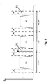
- the useful signal energy SE is equally distributed almost over the entire CATV channel bandwidth ( FIG,. 1 shows three consecutive channels K N-1 , K N , K N+1 ).
- the guard band GB does not contain energy useful for service transmission.
- the tagging signal TS is introduced into this part of the spectrum by combining it with all signals in the headend.
- a typical CATV system shown in FIG. 2 consists of two parts.
- a complex CATV signal is prepared in the headend 1 for transmission to subscribers in the distribution network 2 .
- the service sources SS 1 - SSn (TV, radio, video, data, etc.) are coupled to the input ports of the respective channel modulators (M 1 - M n ), which include carrier frequency generators.
- the modulators M modulate the service signals into channels for placement in the CATV network.
- the outputs of the channel modulators M are then coupled to the main combiner MC.
- the combiner combines all the modulated channel signals into one complex signal CS.
- the tagger T generates the modulated carrier frequency or frequencies TF.
- the output of the tagger T is also connected to the main combiner MC.
- the complex signal CS is transmitted in the CATV distribution network 2. If there is a leakage source LS, the complex signal CS is radiated from the network structure.
- the leakage meter or detector LM 1 receives a signal on the frequency TF.
- the meter LM 1 measures the leak magnitude and checks whether the tagging information is present on the frequency TF. The meter LM1 will recognize the detected signal as a leakage from the network under test.
- the leakage meter LM2 can receive the interfering signal.
- the interfering signal does not contain the tagging information, so the received signal will not be recognized as a leak from the network under test.
- FIG. 3 shows an example of a CATV network which consists of the headend and three sub-networks (PA, PB and PC).
- the subnetwork PA is connected with the subnetwork PB via the very narrow stopband filter FB and with the subnetwork PC via a similar stopband filter FC having a different center frequency.
- the tagger T output is connected to the main combiner C together with the service signals SS 1 - SSn.
- the tagger T generates three narrowband, modulated tagging signals A, B and C, as shown in FIG. 4 .
- the complex signal is transmitted though the network.
- a leakage meter or detector can be moved along all the branches of the network.
- the leakage meter LM can receive the signal radiated by the leak source LS1.
- the signal spectrum will contain three tagging signals with the equal amplitude, as shown in FIG. 4a , or with the amplitude ratio A : B : C exactly the same as the ratio generated in the tagger T.
- the meter LM should know this ratio and may learn it during a meter calibration procedure in the headend or subnetwork PA. This is the spectral signature of the signals radiated from the subnetwork PA.
- the narrow stopband filter F2 reduces the amplitude of the tagging signal B, while the filter F3 suppresses the amplitude of the tagging signal C. If the meter LM receives the signal from the source LS2, it will see the signal signature shown in FIG. 4b . Thus, the signal processing circuit of the meter LM can recognize the leak as radiated from the subnetwork PB. Similarly, if the meter LM receives the signal signature from the source LS3, shown in FIG. 4c , it will recognize it as one coming from the subnetwork PC.
- the tagging information carried by the tagging signals allows for the recognition of the signals coming from the network being tested. If the meter LM does not recognize the tagging information (interference on the frequencies of the tagging signals), the received signal will be ignored and the leak will not be detected.
- FIG. 5 presents a CATV network topology, which is currently quite common in many countries. It consists of two parts. The first part is the main distribution network DN belonging to one operator. The second part consists of the home wirings HW in subscribers' homes. The home wirings HW are connected to the distribution network DN via the connecting points CP.
- the tagger in the headend H generates two tagging frequencies - one slightly below the radio FM band (e.g., 80 MHz), and the second frequency in the III TV band (e.g., 115 MHz). Both tagging signals should be modulated with the tagging information.
- connection points CP should contain a passive or active device reducing the signal amplitude on the first frequency (e.g., a highpass filter with 88 MHz cutoff frequency in our case).
- the filter should suppress the first frequency signal amplitude at least 6-10 dB.
- the leakage meter or detector LM should be calibrated in the headend H or in the distribution network DN in order to learn the amplitude ratio of the tagging signals on the first and second frequency.
- the meter LM receives the signal radiated from the leakage source LS1, it will recognize that the 80 MHz tagging signal amplitude is reduced, so the amplitude ratio of the tagging signals differs from the ratio measured in the headend. As a consequence, the meter LM will recognize the leak as one coming from the second part of the network (not belonging to DN). Similarly, if the meter LM receives the signal leaking from LS2, it will recognize it as one coming from the DN part of the CATV network.
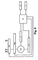
- FIG. 6 presents a block diagram of the leakage meter and/or detector which uses the method of signal tagging according to the invention.
- the apparatus for leakage measurement and/or detection according to the method described herein has good sensitivity, dynamic range and the detection ability of tagging signals which are placed in the narrow guard band GB.
- the meter and/or detector has a built-in internal antenna and allows for the connection of external measurement antennas (e.g., kept in hand or placed on a vehicle roof).
- the signal received by the antenna is amplified in the input low noise amplifier LNA.
- LNA low noise amplifier
- the amplified signal appears at the input of the mixer MX.
- the second input of the mixer is connected to the variable local oscillator LO.
- the mixer MX shifts the input signal on the frequency axis by the frequency of the local oscillator signal.
- the signal at the mixer output has the frequency lying within the bandwidth of the narrowband filter F (the bandwidth is from a few kHz up to several kHz).
- the filter F attenuates all the signals lying outside the guard band GB and coming from the CATV network under test or terrestrial sources which can interfere with the tagging signal.
- the parameters of the filter F (bandwidth, frequency response slope) have substantial influence on the correct detection and measurement of the leaking signal.
- the output signal of the filter F enters the input of the microprocessor MIC.
- the microprocessor MIC has control functions (it controls the antenna switch AS, the amplifier LNA, the oscillator LO, the screen S, and the keyboard K) and digitally processes the signals.
- the digital signal processing in the microprocessor MIC comprises sampling and quantization of the input signal as well as the recognition of the spectrum components carrying the tagging information.
- the detection of the spectrum components with the tagging information is based on the fast Fourier transform (FFT) algorithm.
- FFT fast Fourier transform
- the microprocessor MIC also determines the amplitude of the received leakage signal. Information about the leak magnitude and the presence of the tagging signal (identification of the network or subnetwork) is displayed on the screen of the apparatus. The usage of the microprocessor allows for the correction of the systematic errors. The correction values added to the measurement results are saved in the microprocessor memory during the periodical calibration of the meter/detector.
- An alternative example of the leakage meter/detector embodiment according to the invention has a different microprocessor program, which uses the discrete cosine transform (DCT) for detection of the spectrum components carrying the tagging information.
- DCT discrete cosine transform
Landscapes
- Engineering & Computer Science (AREA)
- Health & Medical Sciences (AREA)
- Biomedical Technology (AREA)
- General Health & Medical Sciences (AREA)
- Multimedia (AREA)
- Signal Processing (AREA)
- Testing, Inspecting, Measuring Of Stereoscopic Televisions And Televisions (AREA)
Applications Claiming Priority (1)
| Application Number | Priority Date | Filing Date | Title |
|---|---|---|---|
| PL391095A PL227094B1 (pl) | 2010-04-29 | 2010-04-29 | Sposób znakowania sygnałów uzywanych dowykrywania ipomiaru wycieków wsieciach telewizji kablowej oraz urzadzenie dowykrywania i/lub pomiaru wycieków znakowanych tym sposobem |
Publications (3)
| Publication Number | Publication Date |
|---|---|
| EP2384015A2 true EP2384015A2 (fr) | 2011-11-02 |
| EP2384015A3 EP2384015A3 (fr) | 2015-09-02 |
| EP2384015B1 EP2384015B1 (fr) | 2020-04-01 |
Family
ID=44351479
Family Applications (1)
| Application Number | Title | Priority Date | Filing Date |
|---|---|---|---|
| EP11460021.6A Active EP2384015B1 (fr) | 2010-04-29 | 2011-04-29 | Procédé d'utilisation de signaux marqués pour la détection et la mesure de fuite dans des réseaux de télévision par câble |
Country Status (3)
| Country | Link |
|---|---|
| US (1) | US8856850B2 (fr) |
| EP (1) | EP2384015B1 (fr) |
| PL (1) | PL227094B1 (fr) |
Cited By (1)
| Publication number | Priority date | Publication date | Assignee | Title |
|---|---|---|---|---|
| WO2013106019A2 (fr) | 2011-04-06 | 2013-07-18 | Comsonics, Inc. | Détection et mesure de défaut de blindage dans un environnement de télécommunication câblé à modulation d'amplitude en quadrature |
Families Citing this family (16)
| Publication number | Priority date | Publication date | Assignee | Title |
|---|---|---|---|---|
| US8650605B2 (en) | 2012-04-26 | 2014-02-11 | Arcom Digital, Llc | Low-cost leakage detector for a digital HFC network |
| US9491027B2 (en) * | 2011-04-06 | 2016-11-08 | Comsonics, Inc. | Miniature mobile marker system and method |
| WO2013003301A1 (fr) * | 2011-06-27 | 2013-01-03 | Trilithic, Inc. | Procédé permettant de détecter une fuite dans des réseaux à modulation numérique |
| WO2014062649A2 (fr) * | 2012-10-15 | 2014-04-24 | Trilithic, Inc. | Certification à domicile fondée sur des icônes, procédé de recherche de fuites à l'intérieur d'un domicile, et pad d'appariement d'antennes |
| US9882668B2 (en) | 2014-09-18 | 2018-01-30 | Arcom Digital, Llc | Detecting leakage of OFDM signals from an HFC network |
| US9832089B2 (en) | 2015-01-07 | 2017-11-28 | Arcom Digital, Llc | Detecting leakage of OFDM signals from an HFC network |
| US10187112B2 (en) | 2015-02-04 | 2019-01-22 | Viavi Solutions, Inc. | Leakage detection in DOCSIS 3.1 environment |
| US9882663B2 (en) | 2016-03-17 | 2018-01-30 | Arcom Digital, Llc | Doppler location of signal leaks in an HFC network |
| US10158423B2 (en) | 2017-01-31 | 2018-12-18 | Arcom Digital, Llc | Communicating network maintenance data in a cable system |
| US10707917B2 (en) | 2017-11-08 | 2020-07-07 | Viavi Solutions, Inc. | Instrument, system, and method for locating a leakage source |
| DE102018002661A1 (de) * | 2018-03-31 | 2019-10-02 | Heinz Lindenmeier | Antennen-Einrichtung für die bidirektionale Kommunikation auf Fahrzeugen |
| JP2020005185A (ja) * | 2018-06-29 | 2020-01-09 | ルネサスエレクトロニクス株式会社 | 通信装置 |
| CN109669132B (zh) * | 2019-01-21 | 2020-09-22 | 西北工业大学 | 一种基于变分贝叶斯滤波的电池荷电状态估计方法 |
| US11356178B2 (en) * | 2019-11-04 | 2022-06-07 | Arcom Digital, Llc | Monitoring leakage in aeronautical band of high split HFC |
| US11736214B2 (en) | 2019-11-04 | 2023-08-22 | Arcom Digital, Llc | Monitoring leakage in aeronautical band of high split HFC |
| US11758362B2 (en) * | 2021-04-02 | 2023-09-12 | Comcast Cable Communications, Llc | Methods and systems for determining signal leaks in a network |
Citations (6)
| Publication number | Priority date | Publication date | Assignee | Title |
|---|---|---|---|---|
| US4072899A (en) | 1976-04-26 | 1978-02-07 | Comsonics, Inc. | RF leak detector |
| US4237486A (en) | 1978-11-09 | 1980-12-02 | Comsonics, Inc. | Compatible transmission of an encoded signal with a television |
| US5608428A (en) | 1994-06-09 | 1997-03-04 | Trilithic, Inc. | Radio frequency leakage detection system for CATV system |
| US6118975A (en) | 1997-12-02 | 2000-09-12 | Wavetek Wandel Goltermann, Inc. | Method and apparatus for leakage detection using pulsed RF tagging signal |
| US6307593B1 (en) | 1997-10-03 | 2001-10-23 | Wavetek Corporation | Pulsed leakage tagging signal |
| US6804826B1 (en) | 1999-07-28 | 2004-10-12 | Trilithic, Inc. | Radio frequency leakage detection system for CATV system |
Family Cites Families (8)
| Publication number | Priority date | Publication date | Assignee | Title |
|---|---|---|---|---|
| US3978282A (en) * | 1971-02-04 | 1976-08-31 | Avantek, Inc. | Apparatus and method for measuring the transmission characteristics of a network |
| US5473361A (en) * | 1993-01-19 | 1995-12-05 | Tektronix, Inc. | Cable television test and measurement system |
| US6018358A (en) * | 1994-06-09 | 2000-01-25 | Trilithic, Inc. | Radio frequency leakage detection system for CATV system |
| US6334219B1 (en) * | 1994-09-26 | 2001-12-25 | Adc Telecommunications Inc. | Channel selection for a hybrid fiber coax network |
| US6310646B1 (en) * | 1996-11-29 | 2001-10-30 | Wavetek Corporation | Method and apparatus for measuring a radio frequency signal having program information and control information |
| WO2001010123A1 (fr) * | 1999-07-28 | 2001-02-08 | Trilithic, Inc. | Detection de fuite d'ondes radioelectriques, destinee a un systeme de teledistribution |
| US6559756B2 (en) * | 2001-06-13 | 2003-05-06 | Scientific-Atlanta, Inc. | Ingress monitoring device in a broadband communications system |
| US7548201B2 (en) * | 2003-04-16 | 2009-06-16 | Cable Leakage Technologies, Inc. | Method and system for automatically analyzing and modifying cable television signal leak information |
-
2010
- 2010-04-29 PL PL391095A patent/PL227094B1/pl unknown
- 2010-12-15 US US12/969,538 patent/US8856850B2/en not_active Expired - Fee Related
-
2011
- 2011-04-29 EP EP11460021.6A patent/EP2384015B1/fr active Active
Patent Citations (7)
| Publication number | Priority date | Publication date | Assignee | Title |
|---|---|---|---|---|
| US4072899A (en) | 1976-04-26 | 1978-02-07 | Comsonics, Inc. | RF leak detector |
| US4237486A (en) | 1978-11-09 | 1980-12-02 | Comsonics, Inc. | Compatible transmission of an encoded signal with a television |
| US5608428A (en) | 1994-06-09 | 1997-03-04 | Trilithic, Inc. | Radio frequency leakage detection system for CATV system |
| US6307593B1 (en) | 1997-10-03 | 2001-10-23 | Wavetek Corporation | Pulsed leakage tagging signal |
| US6600515B2 (en) | 1997-10-03 | 2003-07-29 | Wavetek Corporation | Pulsed leakage tagging signal |
| US6118975A (en) | 1997-12-02 | 2000-09-12 | Wavetek Wandel Goltermann, Inc. | Method and apparatus for leakage detection using pulsed RF tagging signal |
| US6804826B1 (en) | 1999-07-28 | 2004-10-12 | Trilithic, Inc. | Radio frequency leakage detection system for CATV system |
Cited By (1)
| Publication number | Priority date | Publication date | Assignee | Title |
|---|---|---|---|---|
| WO2013106019A2 (fr) | 2011-04-06 | 2013-07-18 | Comsonics, Inc. | Détection et mesure de défaut de blindage dans un environnement de télécommunication câblé à modulation d'amplitude en quadrature |
Also Published As
| Publication number | Publication date |
|---|---|
| EP2384015B1 (fr) | 2020-04-01 |
| US20110267474A1 (en) | 2011-11-03 |
| PL391095A1 (pl) | 2011-11-07 |
| PL227094B1 (pl) | 2017-10-31 |
| EP2384015A3 (fr) | 2015-09-02 |
| US8856850B2 (en) | 2014-10-07 |
Similar Documents
| Publication | Publication Date | Title |
|---|---|---|
| EP2384015B1 (fr) | Procédé d'utilisation de signaux marqués pour la détection et la mesure de fuite dans des réseaux de télévision par câble | |
| US10404388B2 (en) | Detecting signal leakage in cable networks | |
| US7395548B2 (en) | System and method for signal validation and leakage detection | |
| CN101478656B (zh) | 一种同频干扰滤波方法及同频干扰滤波装置 | |
| US6600515B2 (en) | Pulsed leakage tagging signal | |
| US6313874B1 (en) | Method and apparatus for direct detection of communication system leakage signals | |
| US20060248565A1 (en) | Antenna for cable ingress/egress management signaling | |
| US20140307565A1 (en) | Systems and methods for tv white space spectrum sensing | |
| Lysko et al. | The television white space opportunity in Southern Africa: from field measurements to quantifying white spaces | |
| KR101040256B1 (ko) | 방탐 정확도가 향상된 신호 방향 탐지 시스템 및 그 방법 | |
| JP6936582B2 (ja) | 漏洩電波検出装置 | |
| Kalliovaara et al. | 700 MHz band LTE uplink interference to DTT reception system cabling | |
| Rhodes et al. | Interference mitigation for improved DTV reception | |
| Wu et al. | Canadian digital terrestrial television system technical parameters | |
| EP2519015B1 (fr) | Procédé d`étiquetage de signaux utilisés pour la détection des fuites et la mesure dans les réseaux de transmission de données xDSL et appareil pour la détection et/ou mesure des sources de fuites étiquetées grâce à ce procédé | |
| JP2023118008A (ja) | 衛星放送用の受信検査装置 | |
| O'Leary | Field trials of an MPEG2 distributed single frequency network | |
| O'Leary | Digital/analogue co-channel protection ratio field measurements | |
| JPH0426276B2 (fr) | ||
| JP5712116B2 (ja) | 歪測定方法及び歪測定装置 | |
| Bedicks et al. | Interference from FM stations to ISDB-T B DTV reception | |
| JP2024019868A (ja) | 衛星放送受信用の周波数変換装置、及び電力測定システム | |
| Rhodes | Non-invasive testing methods to determine the RF performance of consumer DTV receiving appliances | |
| Buck et al. | GPS RF interference via a TV video signal | |
| Krall | RF and IF measurements in TV satellite transmission |
Legal Events
| Date | Code | Title | Description |
|---|---|---|---|
| AK | Designated contracting states |
Kind code of ref document: A2 Designated state(s): AL AT BE BG CH CY CZ DE DK EE ES FI FR GB GR HR HU IE IS IT LI LT LU LV MC MK MT NL NO PL PT RO RS SE SI SK SM TR |
|
| AX | Request for extension of the european patent |
Extension state: BA ME |
|
| PUAI | Public reference made under article 153(3) epc to a published international application that has entered the european phase |
Free format text: ORIGINAL CODE: 0009012 |
|
| 17P | Request for examination filed |
Effective date: 20121116 |
|
| PUAL | Search report despatched |
Free format text: ORIGINAL CODE: 0009013 |
|
| AK | Designated contracting states |
Kind code of ref document: A3 Designated state(s): AL AT BE BG CH CY CZ DE DK EE ES FI FR GB GR HR HU IE IS IT LI LT LU LV MC MK MT NL NO PL PT RO RS SE SI SK SM TR |
|
| AX | Request for extension of the european patent |
Extension state: BA ME |
|
| RIC1 | Information provided on ipc code assigned before grant |
Ipc: H04N 17/00 20060101AFI20150730BHEP |
|
| STAA | Information on the status of an ep patent application or granted ep patent |
Free format text: STATUS: EXAMINATION IS IN PROGRESS |
|
| 17Q | First examination report despatched |
Effective date: 20170718 |
|
| GRAP | Despatch of communication of intention to grant a patent |
Free format text: ORIGINAL CODE: EPIDOSNIGR1 |
|
| STAA | Information on the status of an ep patent application or granted ep patent |
Free format text: STATUS: GRANT OF PATENT IS INTENDED |
|
| GRAS | Grant fee paid |
Free format text: ORIGINAL CODE: EPIDOSNIGR3 |
|
| INTG | Intention to grant announced |
Effective date: 20200129 |
|
| RIN1 | Information on inventor provided before grant (corrected) |
Inventor name: SZOSTKA, JAROSLAW Inventor name: SALA, WOJCIECH |
|
| GRAA | (expected) grant |
Free format text: ORIGINAL CODE: 0009210 |
|
| STAA | Information on the status of an ep patent application or granted ep patent |
Free format text: STATUS: THE PATENT HAS BEEN GRANTED |
|
| AK | Designated contracting states |
Kind code of ref document: B1 Designated state(s): AL AT BE BG CH CY CZ DE DK EE ES FI FR GB GR HR HU IE IS IT LI LT LU LV MC MK MT NL NO PL PT RO RS SE SI SK SM TR |
|
| REG | Reference to a national code |
Ref country code: GB Ref legal event code: FG4D |
|
| REG | Reference to a national code |
Ref country code: CH Ref legal event code: EP Ref country code: AT Ref legal event code: REF Ref document number: 1252884 Country of ref document: AT Kind code of ref document: T Effective date: 20200415 |
|
| REG | Reference to a national code |
Ref country code: DE Ref legal event code: R096 Ref document number: 602011065959 Country of ref document: DE |
|
| REG | Reference to a national code |
Ref country code: IE Ref legal event code: FG4D |
|
| PG25 | Lapsed in a contracting state [announced via postgrant information from national office to epo] |
Ref country code: BG Free format text: LAPSE BECAUSE OF FAILURE TO SUBMIT A TRANSLATION OF THE DESCRIPTION OR TO PAY THE FEE WITHIN THE PRESCRIBED TIME-LIMIT Effective date: 20200701 |
|
| REG | Reference to a national code |
Ref country code: NL Ref legal event code: MP Effective date: 20200401 |
|
| REG | Reference to a national code |
Ref country code: LT Ref legal event code: MG4D |
|
| PG25 | Lapsed in a contracting state [announced via postgrant information from national office to epo] |
Ref country code: LT Free format text: LAPSE BECAUSE OF FAILURE TO SUBMIT A TRANSLATION OF THE DESCRIPTION OR TO PAY THE FEE WITHIN THE PRESCRIBED TIME-LIMIT Effective date: 20200401 Ref country code: PT Free format text: LAPSE BECAUSE OF FAILURE TO SUBMIT A TRANSLATION OF THE DESCRIPTION OR TO PAY THE FEE WITHIN THE PRESCRIBED TIME-LIMIT Effective date: 20200817 Ref country code: FI Free format text: LAPSE BECAUSE OF FAILURE TO SUBMIT A TRANSLATION OF THE DESCRIPTION OR TO PAY THE FEE WITHIN THE PRESCRIBED TIME-LIMIT Effective date: 20200401 Ref country code: SE Free format text: LAPSE BECAUSE OF FAILURE TO SUBMIT A TRANSLATION OF THE DESCRIPTION OR TO PAY THE FEE WITHIN THE PRESCRIBED TIME-LIMIT Effective date: 20200401 Ref country code: GR Free format text: LAPSE BECAUSE OF FAILURE TO SUBMIT A TRANSLATION OF THE DESCRIPTION OR TO PAY THE FEE WITHIN THE PRESCRIBED TIME-LIMIT Effective date: 20200702 Ref country code: IS Free format text: LAPSE BECAUSE OF FAILURE TO SUBMIT A TRANSLATION OF THE DESCRIPTION OR TO PAY THE FEE WITHIN THE PRESCRIBED TIME-LIMIT Effective date: 20200801 Ref country code: NO Free format text: LAPSE BECAUSE OF FAILURE TO SUBMIT A TRANSLATION OF THE DESCRIPTION OR TO PAY THE FEE WITHIN THE PRESCRIBED TIME-LIMIT Effective date: 20200701 Ref country code: NL Free format text: LAPSE BECAUSE OF FAILURE TO SUBMIT A TRANSLATION OF THE DESCRIPTION OR TO PAY THE FEE WITHIN THE PRESCRIBED TIME-LIMIT Effective date: 20200401 Ref country code: CZ Free format text: LAPSE BECAUSE OF FAILURE TO SUBMIT A TRANSLATION OF THE DESCRIPTION OR TO PAY THE FEE WITHIN THE PRESCRIBED TIME-LIMIT Effective date: 20200401 |
|
| REG | Reference to a national code |
Ref country code: DE Ref legal event code: R119 Ref document number: 602011065959 Country of ref document: DE |
|
| REG | Reference to a national code |
Ref country code: AT Ref legal event code: MK05 Ref document number: 1252884 Country of ref document: AT Kind code of ref document: T Effective date: 20200401 |
|
| PG25 | Lapsed in a contracting state [announced via postgrant information from national office to epo] |
Ref country code: RS Free format text: LAPSE BECAUSE OF FAILURE TO SUBMIT A TRANSLATION OF THE DESCRIPTION OR TO PAY THE FEE WITHIN THE PRESCRIBED TIME-LIMIT Effective date: 20200401 Ref country code: HR Free format text: LAPSE BECAUSE OF FAILURE TO SUBMIT A TRANSLATION OF THE DESCRIPTION OR TO PAY THE FEE WITHIN THE PRESCRIBED TIME-LIMIT Effective date: 20200401 Ref country code: LV Free format text: LAPSE BECAUSE OF FAILURE TO SUBMIT A TRANSLATION OF THE DESCRIPTION OR TO PAY THE FEE WITHIN THE PRESCRIBED TIME-LIMIT Effective date: 20200401 |
|
| REG | Reference to a national code |
Ref country code: CH Ref legal event code: PL |
|
| PG25 | Lapsed in a contracting state [announced via postgrant information from national office to epo] |
Ref country code: AL Free format text: LAPSE BECAUSE OF FAILURE TO SUBMIT A TRANSLATION OF THE DESCRIPTION OR TO PAY THE FEE WITHIN THE PRESCRIBED TIME-LIMIT Effective date: 20200401 |
|
| PG25 | Lapsed in a contracting state [announced via postgrant information from national office to epo] |
Ref country code: IT Free format text: LAPSE BECAUSE OF FAILURE TO SUBMIT A TRANSLATION OF THE DESCRIPTION OR TO PAY THE FEE WITHIN THE PRESCRIBED TIME-LIMIT Effective date: 20200401 Ref country code: LI Free format text: LAPSE BECAUSE OF NON-PAYMENT OF DUE FEES Effective date: 20200430 Ref country code: MC Free format text: LAPSE BECAUSE OF FAILURE TO SUBMIT A TRANSLATION OF THE DESCRIPTION OR TO PAY THE FEE WITHIN THE PRESCRIBED TIME-LIMIT Effective date: 20200401 Ref country code: SM Free format text: LAPSE BECAUSE OF FAILURE TO SUBMIT A TRANSLATION OF THE DESCRIPTION OR TO PAY THE FEE WITHIN THE PRESCRIBED TIME-LIMIT Effective date: 20200401 Ref country code: CH Free format text: LAPSE BECAUSE OF NON-PAYMENT OF DUE FEES Effective date: 20200430 Ref country code: EE Free format text: LAPSE BECAUSE OF FAILURE TO SUBMIT A TRANSLATION OF THE DESCRIPTION OR TO PAY THE FEE WITHIN THE PRESCRIBED TIME-LIMIT Effective date: 20200401 Ref country code: DK Free format text: LAPSE BECAUSE OF FAILURE TO SUBMIT A TRANSLATION OF THE DESCRIPTION OR TO PAY THE FEE WITHIN THE PRESCRIBED TIME-LIMIT Effective date: 20200401 Ref country code: DE Free format text: LAPSE BECAUSE OF NON-PAYMENT OF DUE FEES Effective date: 20201103 Ref country code: AT Free format text: LAPSE BECAUSE OF FAILURE TO SUBMIT A TRANSLATION OF THE DESCRIPTION OR TO PAY THE FEE WITHIN THE PRESCRIBED TIME-LIMIT Effective date: 20200401 Ref country code: LU Free format text: LAPSE BECAUSE OF NON-PAYMENT OF DUE FEES Effective date: 20200429 Ref country code: ES Free format text: LAPSE BECAUSE OF FAILURE TO SUBMIT A TRANSLATION OF THE DESCRIPTION OR TO PAY THE FEE WITHIN THE PRESCRIBED TIME-LIMIT Effective date: 20200401 Ref country code: RO Free format text: LAPSE BECAUSE OF FAILURE TO SUBMIT A TRANSLATION OF THE DESCRIPTION OR TO PAY THE FEE WITHIN THE PRESCRIBED TIME-LIMIT Effective date: 20200401 |
|
| REG | Reference to a national code |
Ref country code: BE Ref legal event code: MM Effective date: 20200430 |
|
| PLBE | No opposition filed within time limit |
Free format text: ORIGINAL CODE: 0009261 |
|
| STAA | Information on the status of an ep patent application or granted ep patent |
Free format text: STATUS: NO OPPOSITION FILED WITHIN TIME LIMIT |
|
| PG25 | Lapsed in a contracting state [announced via postgrant information from national office to epo] |
Ref country code: PL Free format text: LAPSE BECAUSE OF FAILURE TO SUBMIT A TRANSLATION OF THE DESCRIPTION OR TO PAY THE FEE WITHIN THE PRESCRIBED TIME-LIMIT Effective date: 20200401 Ref country code: BE Free format text: LAPSE BECAUSE OF NON-PAYMENT OF DUE FEES Effective date: 20200430 Ref country code: SK Free format text: LAPSE BECAUSE OF FAILURE TO SUBMIT A TRANSLATION OF THE DESCRIPTION OR TO PAY THE FEE WITHIN THE PRESCRIBED TIME-LIMIT Effective date: 20200401 |
|
| 26N | No opposition filed |
Effective date: 20210112 |
|
| GBPC | Gb: european patent ceased through non-payment of renewal fee |
Effective date: 20200701 |
|
| PG25 | Lapsed in a contracting state [announced via postgrant information from national office to epo] |
Ref country code: IE Free format text: LAPSE BECAUSE OF NON-PAYMENT OF DUE FEES Effective date: 20200429 Ref country code: FR Free format text: LAPSE BECAUSE OF NON-PAYMENT OF DUE FEES Effective date: 20200601 Ref country code: GB Free format text: LAPSE BECAUSE OF NON-PAYMENT OF DUE FEES Effective date: 20200701 |
|
| PG25 | Lapsed in a contracting state [announced via postgrant information from national office to epo] |
Ref country code: SI Free format text: LAPSE BECAUSE OF FAILURE TO SUBMIT A TRANSLATION OF THE DESCRIPTION OR TO PAY THE FEE WITHIN THE PRESCRIBED TIME-LIMIT Effective date: 20200401 |
|
| PG25 | Lapsed in a contracting state [announced via postgrant information from national office to epo] |
Ref country code: TR Free format text: LAPSE BECAUSE OF FAILURE TO SUBMIT A TRANSLATION OF THE DESCRIPTION OR TO PAY THE FEE WITHIN THE PRESCRIBED TIME-LIMIT Effective date: 20200401 Ref country code: MT Free format text: LAPSE BECAUSE OF FAILURE TO SUBMIT A TRANSLATION OF THE DESCRIPTION OR TO PAY THE FEE WITHIN THE PRESCRIBED TIME-LIMIT Effective date: 20200401 Ref country code: CY Free format text: LAPSE BECAUSE OF FAILURE TO SUBMIT A TRANSLATION OF THE DESCRIPTION OR TO PAY THE FEE WITHIN THE PRESCRIBED TIME-LIMIT Effective date: 20200401 |
|
| PG25 | Lapsed in a contracting state [announced via postgrant information from national office to epo] |
Ref country code: MK Free format text: LAPSE BECAUSE OF FAILURE TO SUBMIT A TRANSLATION OF THE DESCRIPTION OR TO PAY THE FEE WITHIN THE PRESCRIBED TIME-LIMIT Effective date: 20200401 |