EP2383597A1 - Lens apparatus - Google Patents
Lens apparatus Download PDFInfo
- Publication number
- EP2383597A1 EP2383597A1 EP11162933A EP11162933A EP2383597A1 EP 2383597 A1 EP2383597 A1 EP 2383597A1 EP 11162933 A EP11162933 A EP 11162933A EP 11162933 A EP11162933 A EP 11162933A EP 2383597 A1 EP2383597 A1 EP 2383597A1
- Authority
- EP
- European Patent Office
- Prior art keywords
- focus
- driving
- lens
- defocus amount
- focus lens
- Prior art date
- Legal status (The legal status is an assumption and is not a legal conclusion. Google has not performed a legal analysis and makes no representation as to the accuracy of the status listed.)
- Granted
Links
Images


Classifications
-
- G—PHYSICS
- G02—OPTICS
- G02B—OPTICAL ELEMENTS, SYSTEMS OR APPARATUS
- G02B7/00—Mountings, adjusting means, or light-tight connections, for optical elements
- G02B7/28—Systems for automatic generation of focusing signals
- G02B7/282—Autofocusing of zoom lenses
-
- H—ELECTRICITY
- H04—ELECTRIC COMMUNICATION TECHNIQUE
- H04N—PICTORIAL COMMUNICATION, e.g. TELEVISION
- H04N23/00—Cameras or camera modules comprising electronic image sensors; Control thereof
- H04N23/60—Control of cameras or camera modules
- H04N23/67—Focus control based on electronic image sensor signals
- H04N23/672—Focus control based on electronic image sensor signals based on the phase difference signals
Definitions
- the present invention relates to a lens apparatus having an automatic focus adjusting function, which is to be used for optical apparatuses such as a television lens and a video lens.
- the present invention also relates to an image pickup system including the lens apparatus.
- AF autofocus
- image taking apparatuses such as a camera and a video camera.
- the following automatic focus adjusting method is widely known. That is, beams coming from a subject through different exit pupil regions of an image taking lens are imaged onto a pair of line sensors, and a pair of image signals are obtained through photoelectric conversion performed on subject images, to thereby determine a relative position displacement amount of the pair of image signals thus obtained. Based on the displacement amount, a defocus amount of the subject is calculated, and the image taking lens is thus driven.
- An in-focus position of a focus lens based on a subject distance can be determined in the AF system employing phase difference detection, and hence this AF system has such a feature that a focus state may be obtained more quickly than a contrast AF system.
- Japanese Patent Application Laid-Open No. 2005-292779 discloses an autofocus system in which a focus lens is moved based on a contrast of a subject image.
- the autofocus system includes a focus demand that enables manual setting of a driving speed of the focus lens and a cut-off frequency of a filter for detecting the contrast. At a speed designated with the focus demand, the focus lens is driven to an in-focus position.
- Japanese Patent Application Laid-Open No. 2009-145645 discloses that a focus lens is driven at different driving speeds in two regions within a movable range of the focus lens, wherein the two regions are different from each other in moving amount of the focus lens relative to a change amount of a focus state.
- a depth of field in particular, near-side depth of field
- a depth of field is shallower (smaller) on a close side than on an infinity side in terms of a subject distance, and hence when the focus lens is driven at the same speed, an image blur amount changes slowly on the infinity side while changing quickly on the close side.
- the driving speed of the focus lens is changed in two stages depending on a focus range.
- a depth of focus when a depth of focus is defined as a degree of a defocus amount D within which it may be determined that an in-focus state is obtained, the depth of focus may be expressed as 2 ⁇ Fno ⁇ , where Fno represents an f-number and ⁇ represents a permissible circle of confusion.
- the depth of focus is constant even at any focal length and subject distance.
- the depth of field which indicates a range within which the subject may be determined to be actually in-focus, is expressed as the following expressions (1) and (2), where d1 and d2 represent a near-side depth of field and a far-side depth of field, respectively, f represents a focal length of the lens and L represents a subject distance.
- the depths of field d1 and d2 are smaller as the subject distance L is smaller, and the depths of field are also smaller as the focal length f of the lens is larger.
- FIG. 6 shows a relationship between the defocus amount indicating an in-focus degree and the subject distance, and between the defocus amount and the focal length of the lens.
- FIG. 6 shows a change in defocus amount at the same driving amount of the focus lens.
- the change in defocus amount relative to the change in driving amount of the focus lens is extremely small. In other words, in the same defocus amount, the driving amount of the focus lens necessary to obtain the in-focus state is larger as the focal length of the lens is smaller.
- FIG. 7 shows an example of a focus lens driving locus in a case where a zoom position is in a telephoto side.
- the axis of abscissa represents time and the axis of ordinate represents a position of the focus lens.
- a depth of focus D and a threshold value 2D of the defocus amount respectively indicate the positions of the focus lens corresponding thereto. The same applies to the description that is given later referring to FIGS. 3 , 4 , and 8 .
- the focus lens is driven at high speed in a direction in which the defocus amount is zero.
- the focus state is monitored as necessary even during the driving of the focus lens, and when the defocus amount reaches to a predetermined value (threshold value corresponding to positive/negative focal depths), the driving speed of the focus lens is shifted to a low speed.
- the focus lens is driven at low speed, and is stopped at an in-focus point, at which the defocus amount is zero.
- FIG. 8 shows an example of a focus lens driving locus in a case where the driving method for the focus lens on the telephoto side shown in FIG. 7 is applied to the wide-angle side.
- the focus lens is driven at high speed in the direction in which the defocus amount is zero.
- the focus state is monitored as necessary even during the driving of the focus lens, and when the defocus amount reaches to the predetermined value (threshold value corresponding to the positive/negative focal depths), the driving speed of the focus lens is shifted to low speed.
- the focus lens is driven at low speed, and is stopped at the in-focus point, at which the defocus amount is zero.
- the depth of focus is large and hence the position of the focus lens within the threshold value of the low speed driving is very distant from the in-focus point. As a result, it takes an extremely long period of time for the low speed driving (from the time t1 to the time t2).
- the threshold value for determining the shift from the high speed driving to the low speed driving is set based on the defocus amount (depth of focus)
- the depth of field corresponding to the depth of focus is large on the wide-angle side, and hence on the wide-angle side
- the focus lens is shifted to the low speed driving at a position that is more distant from the in-focus point than on the telephoto side. Therefore, when the position of the shift to the low speed driving is determined based on the depth of focus, as shown in FIG. 8 , it takes an extremely long period of time for the low speed driving (from the time t1 to the time t2) on the wide-angle side, with the result that the focus lens cannot be moved quickly to the in-focus point.
- the present invention aims to provide an automatic focus adjusting apparatus capable of quickly obtaining an in-focus state irrespective of a focal length of a lens.
- the present invention provides a lens apparatus including: an image pickup optical system including a focus lens and a zoom lens; a focus detector for detecting a focus state of the image pickup optical system; a defocus amount calculation unit for calculating a defocus amount based on a result of a detection performed by the focus detector; a driving amount calculation unit for calculating a driving amount necessary to drive the focus lens to a focus position based on the defocus amount calculated by the defocus amount calculation unit; and a controller for controlling a driving of the focus lens, in which the controller controls a driving speed of the focus lens depending on the defocus amount calculated by the defocus amount calculation unit and the driving amount calculated by the driving amount calculation unit.
- the lens apparatus having the automatic focus adjusting function which is capable of quickly obtaining the in-focus state irrespective of the focal length of the lens, can be provided.
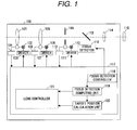
- FIG. 1 is a block diagram according to a first embodiment of the present invention.
- FIG. 2 is a flow chart illustrating operation of a focus lens according to the first embodiment.
- FIG. 3 shows a focus lens locus indicating operation of the focus lens according to the first embodiment.
- FIG. 4 shows a focus lens locus indicating operation of the focus lens according to the first embodiment.
- FIG. 5 is a block diagram according to a second embodiment of the present invention.
- FIG. 6 is a graph showing a defocus amount.
- FIG. 7 shows a focus lens locus indicating operation of a conventional focus lens.
- FIG. 8 shows a focus lens locus indicating operation of the conventional focus lens.
- FIG. 1 illustrates a configuration of a zoom lens apparatus 100, which is a lens apparatus employing an automatic focus adjustment according to a first embodiment of the present invention.
- the zoom lens apparatus 100 includes an image pickup optical system including a focus lens 101, a zoom lens 105 and a movable stop 109.
- the focus lens 101 moves in an optical axis direction to change a position of an image plane of the zoom lens apparatus 100.
- a focus motor 102 is connected to the focus lens 101.
- the focus motor 102 is driven by a focus driver 103 to move the focus lens 101 in the optical axis direction.
- a position of the focus lens 101 is detected by a focus position detector 104.
- the zoom lens 105 moves in the optical axis direction to change a focal length of the zoom lens apparatus 100.
- a zoom motor 106 is connected to the zoom lens 105.
- the zoom motor 106 is driven by a zoom driver 107 to move the zoom lens 105 in the optical axis direction.
- a position of the zoom lens 105 is detected by a zoom position detector 108.
- An iris motor 110 is connected to the movable stop 109.
- the iris motor 110 is driven by an iris driver 111 to drive the movable stop 109.
- a position of the movable stop 109 is detected by an iris position detector 112.
- a beam-splitting prism 113 splits light passing through the focus lens 101 and the zoom lens 105 into two beams.
- the one beam transmitted through the beam-splitting prism 113 enters an image pickup element 115 through a relay lens 114.
- the other beam reflected on the beam-splitting prism 113 enters a focus detector 116.
- the focus detector 116 is constituted by a phase difference detecting lens and a phase difference detection sensor. In the focus detector 116, a pair of images of the two split beams formed by the respective phase difference detecting lenses is subjected to photoelectric conversion by the phase difference detection sensor.
- a zoom lens controller 117 includes a lens controller 121 for driving the focus lens 101 based on a result from a focus detection computing unit 119, and controlling the zoom lens 105 and the movable stop 109.
- a focus detection controller 118 controls accumulation of charges obtained through the photoelectric conversion, which is performed by the phase difference detection sensor of the focus detector 116, and reading of the two images with a necessary amount of charges accumulated by the phase difference detection sensor.
- the focus detection computing unit (defocus amount calculation unit) 119 calculates a phase difference between the pair of image signals obtained through the photoelectric conversion by the focus detector 116, to thereby calculate a defocus amount.
- a target position calculation unit 120 calculates a target position of the focus lens based on the defocus amount calculated by the focus detection computing unit 119.
- the lens controller 121 serving as a controlling unit controls the driving of the focus lens based on the defocus amount calculated by the focus detection computing unit 119 and the target position of the focus lens calculated by the target position calculation unit 120.
- the lens controller 121 includes a driving amount calculation unit for calculating a driving amount necessary to move the focus lens to an in-focus position based on the target position of the focus lens calculated by the target position calculation unit 120.
- a threshold value is set based on the defocus amount corresponding to a depth of focus to drive the focus lens quickly to the in-focus position, and such setting is effective on a telephoto side but is not effective on a wide-angle side.
- a second threshold value effective only on the wide-angle side is also applied in addition to the threshold value based on the defocus amount.
- FIG. 1 Referring to the configuration of FIG. 1 and a flow chart of FIG. 2 , a control method for the driving of the focus lens according to the present invention is described.
- Step S201 of FIG. 2 in response to charge accumulation start instruction for the phase difference detection sensor from the focus detection controller 118, the phase difference detection sensor of the focus detector 116 starts accumulation of charges obtained through the photoelectric conversion, and the process proceeds to Step S202.
- Step S202 the focus detection controller 118 monitors whether or not a signal indicating the finish of accumulation is sent from the phase difference detection sensor of the focus detector 116, and when the accumulation is finished, the process proceeds to Step S203.
- Step S203 the focus detection controller 118 reads a pair of image signals with a necessary amount of charges accumulated in the phase difference detection sensor of the focus detector 116, and the processing proceeds to Step S204.
- Step S204 the focus detection computing unit 119 performs correlation computing on the pair of image signals read from the phase difference detection sensor of the focus detector 116, to thereby calculate a phase difference amount of the two images. Then, the process proceeds to Step S205.
- Step S205 a defocus amount indicating an in-focus degree is calculated based on the phase difference amount calculated by the focus detection computing unit 119, and the process proceeds to Step S206.
- Step S206 the lens controller 121 determines the defocus amount calculated by the focus detection computing unit 119. When the defocus amount is zero, the process proceeds to Step S207. In Step S207, the lens controller 121 determines that an in-focus state is obtained because the defocus amount calculated by the focus detection computing unit 119 is zero, and the lens controller 121 stops driving the focus lens 101. Then, the process returns to Step S201.
- Step S208 the defocus amount calculated by the focus detection computing unit 119 is compared to a predetermined threshold value D to determine whether or not the following expression (3) is satisfied:
- Step S209 based on the defocus amount calculated by the focus detection computing unit 119, the target position calculation unit 120 calculates a target focus position, and the process proceeds to Step S210.
- Step S210 based on the target focus position calculated by the target position calculation unit 120, the lens controller 121 calculates a driving amount of the focus lens with reference to a current position of the focus lens, and the calculated driving amount is compared to a predetermined threshold value P to determine whether or not the following expression (4) is satisfied:
- Step S211 the process proceeds to Step S211. Specifically, when the driving amount necessary to drive the focus lens to the in-focus position (
- the expression (4) is not satisfied, that is, when the driving amount necessary to drive the focus lens to the in-focus position is equal to or larger than the predetermined driving amount, the process proceeds to Step S212.
- the necessary driving amount may be calculated continuously by detecting the position of the focus lens in a predetermined period and using the detection results. Alternatively, the necessary driving amount may be calculated by a difference between the driving amount calculated for the first time and an integrated value of instructions sent to the focus lens.
- the lens controller 121 shifts the driving speed of the focus lens 101 to low speed driving (driving performed at lower speed than high speed driving), and the process returns to Step S201.
- Step S212 the lens controller 121 shifts the driving speed of the focus lens 101 to high speed driving (driving performed at higher speed than the above-mentioned low speed driving), and the process returns to Step S201 to repeat the series of operations.
- FIG. 3 shows a focus lens driving locus in a case where the zoom position is on the telephoto side (on a side on which the focal length of the lens is large).
- the indication of a depth of focus D on the axis of ordinate is shown at a position of the focus lens corresponding to the depth of focus D.
- the defocus amount is equal to or larger than a predetermined defocus amount (in this case, equal to or larger than the threshold value D corresponding to positive/negative focal depths), and hence the focus lens is driven at high speed (first driving speed) in a direction in which the defocus amount is zero.
- a focus state is monitored as necessary even during the driving of the focus lens, and when the defocus amount is smaller than a predetermined value (in this case, threshold value D corresponding to the positive/negative focal depths), the driving speed of the focus lens is shifted to low speed (second driving speed).
- the condition of Step S208 is satisfied and hence the target focus position is calculated in Step S209.
- Step S210 The condition of Step S210 is also satisfied and hence the process proceeds to Step S211, in which the focus lens is driven at low speed during a period from the time t1 to a time t2, and the driving of the focus lens is stopped at an in-focus point, at which the defocus amount is zero.
- FIG. 4 shows a focus lens driving locus in a case where the zoom position is on the wide-angle side (on a side on which the focal length of the lens is small).
- the focus lens is driven at high speed in the direction in which the defocus amount is zero during the period from the time t0 to the time t1.
- the threshold values 2P shown in FIGS. 3 and 4 are actually the same within the entire zoom range but the scale of the axis of ordinate in the graph of FIG. 4 is reduced as compared to the graph of FIG. 3 for convenience of the illustration.
- the focus state is monitored as necessary even during the driving of the focus lens.
- the defocus amount becomes smaller than a predetermined value (in this case, threshold value corresponding to the positive/negative focal depths), and hence the condition of Step S208 is satisfied.
- the driving amount necessary to move the focus lens to the in-focus position is equal to or larger than a predetermined driving amount, that is, the threshold value P, and hence the condition of Step S210 is not satisfied.
- the processing proceeds from Step S210 to Step S212, and the focus lens is driven at high speed.
- the condition of Step S210 is satisfied and hence the focus lens is driven at low speed during the period from the time t1 to the time t2.
- the driving of the focus lens is stopped at the in-focus point of the focus lens, at which the defocus amount is zero.
- the threshold value D is given based on the defocus amount corresponding to the depth of focus.
- the threshold value is set as the defocus amount corresponding to the positive/negative focal depths from the in-focus position.
- the depth of focus is constant irrespective of the focal length, but the depth of field corresponding to the depth of focus is determined as the function of the focal length f as expressed in the expressions (1) and (2).
- the driving amount of the focus lens corresponding to the threshold value D is larger on the wide-angle side than on the telephoto side.
- the threshold value P is an amount corresponding to the driving amount of the focus lens, and is an amount determined based on a driving amount P Wide of the focus lens corresponding to the depth of focus at the wide-angle end.
- the threshold value P may be set as follows:
- the threshold value P may be used in a distinct manner, that is, a threshold value P Far for a case where the in-focus state is obtained from an infinity side and a threshold value P Near for a case where the in-focus state is obtained from a close side may be used.
- FIGS. 3 and 4 each show a range of 2 ⁇ P including the threshold values P on both sides of the in-focus position (wide-angle side and telephoto side). The threshold value P thus set is applied within the entire zoom range according to the flow chart of FIG. 2 .
- the focus lens is driven at high speed to the vicinity of the in-focus position within a large depth of field, and thus the focus lens may be moved to the in-focus position quickly.
- an interval between two images formed on line sensors is smaller on the wide-angle side than on the telephoto side, and hence detection accuracy (resolution) of defocus amount detection is low on the wide-angle side in principle, with the result that the detected defocus amount in the wide-angle side is not as stable as that in the telephoto side.
- the in-focus position that is a focus detection result is not stable but always changes, and accordingly the focus lens needs to respond to the change continuously and sensitively while being driven at high speed, which is not preferred. Further, it is not significant that the focus lens be moved quickly to the in-focus position determined based on the unstable defocus amount fluctuating in a very small range.
- the threshold value P (predetermined driving amount) is set to a value smaller than that of the driving amount of the focus lens corresponding to the depth of focus at the wide-angle end of the image pickup optical system.
- the focal length is large and hence the threshold value D that is set based on the depth of field expressed in each of the expressions (1) and (2) is smaller than the threshold value P. Therefore, the focus lens is driven at high speed to the position indicated by the threshold value D so that the focus lens may be moved to the in-focus position quickly.
- the quick focusing operation is always enabled irrespective of the focal length of the lens.
- FIG. 5 is a configuration diagram according to a second embodiment of the present invention. Description is herein omitted on the same components as those of the first embodiment illustrated in FIG. 1 .
- the configuration according to the second embodiment is different from the configuration according to the first embodiment in that a speed controller 122 is provided.
- the speed controller 122 is connected to the lens controller 121, and is capable of changing the settings of the driving speed of the focus lens and the threshold value at the point of change.
- the speed controller 122 is capable of setting the driving speed of the focus lens for each of the high speed driving and the low speed driving, and of changing the set speed arbitrarily.
- the driving speed for the high speed driving only or the low speed driving only may be set and thereby set the driving speed for the other is set adaptively.
- the speed controller 122 may have a function as a setting unit capable of changing the set value of the threshold value of the defocus amount that is the point of change in driving speed.
- the speed controller 122 may also have a function as a setting unit capable of changing the set value of the focus position threshold value (threshold value P) that is used for changing the driving speed. Accordingly, the focusing speed may be set depending on various image taking scenes.
- an image pickup system including the lens apparatus described in each embodiment above and an image pickup apparatus connected to the lens apparatus, an image pickup system suitable for a camera, a video camera, and the like may be provided.
- a lens apparatus including: an image pickup optical system including a focus lens and a zoom lens; a focus detector for detecting a focus state of the image pickup optical system; a defocus amount calculation unit for calculating a defocus amount based on a result of a detection performed by the focus detector; a driving amount calculation unit for calculating a driving amount necessary to drive the focus lens to a focus position based on the defocus amount calculated by the defocus amount calculation unit; and a controller for controlling a driving of the focus lens, in which the controller controls a driving speed of the focus lens depending on the defocus amount calculated by the defocus amount calculation unit and the driving amount calculated by the driving amount calculation unit.
Landscapes
- Physics & Mathematics (AREA)
- Engineering & Computer Science (AREA)
- Multimedia (AREA)
- Signal Processing (AREA)
- General Physics & Mathematics (AREA)
- Optics & Photonics (AREA)
- Automatic Focus Adjustment (AREA)
- Studio Devices (AREA)
- Lens Barrels (AREA)
- Focusing (AREA)
Abstract
Description
- The present invention relates to a lens apparatus having an automatic focus adjusting function, which is to be used for optical apparatuses such as a television lens and a video lens. The present invention also relates to an image pickup system including the lens apparatus.
- Conventionally, various proposals have been made as autofocus (AF) technologies to be adopted into image taking apparatuses such as a camera and a video camera. For example, the following automatic focus adjusting method is widely known. That is, beams coming from a subject through different exit pupil regions of an image taking lens are imaged onto a pair of line sensors, and a pair of image signals are obtained through photoelectric conversion performed on subject images, to thereby determine a relative position displacement amount of the pair of image signals thus obtained. Based on the displacement amount, a defocus amount of the subject is calculated, and the image taking lens is thus driven.
- An in-focus position of a focus lens based on a subject distance can be determined in the AF system employing phase difference detection, and hence this AF system has such a feature that a focus state may be obtained more quickly than a contrast AF system.
- Japanese Patent Application Laid-Open No.
2005-292779 - Japanese Patent Application Laid-Open No.
2009-145645 - In general, when a depth of focus is defined as a degree of a defocus amount D within which it may be determined that an in-focus state is obtained, the depth of focus may be expressed as 2×Fno×δ, where Fno represents an f-number and δ represents a permissible circle of confusion. Hence, the depth of focus is constant even at any focal length and subject distance. However, the depth of field, which indicates a range within which the subject may be determined to be actually in-focus, is expressed as the following expressions (1) and (2), where d1 and d2 represent a near-side depth of field and a far-side depth of field, respectively, f represents a focal length of the lens and L represents a subject distance.
-

-

- From the above-mentioned expressions, the depths of field d1 and d2 are smaller as the subject distance L is smaller, and the depths of field are also smaller as the focal length f of the lens is larger.
-
FIG. 6 shows a relationship between the defocus amount indicating an in-focus degree and the subject distance, and between the defocus amount and the focal length of the lens.FIG. 6 shows a change in defocus amount at the same driving amount of the focus lens. On a wide-angle side on which the focal length of the lens is small, the change in defocus amount relative to the change in driving amount of the focus lens is extremely small. In other words, in the same defocus amount, the driving amount of the focus lens necessary to obtain the in-focus state is larger as the focal length of the lens is smaller. -
FIG. 7 shows an example of a focus lens driving locus in a case where a zoom position is in a telephoto side. The axis of abscissa represents time and the axis of ordinate represents a position of the focus lens. InFIG. 7 , a depth of focus D and a threshold value 2D of the defocus amount respectively indicate the positions of the focus lens corresponding thereto. The same applies to the description that is given later referring toFIGS. 3 ,4 , and8 . - During a period from a time t0 to a time t1, the focus lens is driven at high speed in a direction in which the defocus amount is zero. The focus state is monitored as necessary even during the driving of the focus lens, and when the defocus amount reaches to a predetermined value (threshold value corresponding to positive/negative focal depths), the driving speed of the focus lens is shifted to a low speed. During a period from the time t1 to a time t2, in which the defocus amount falls within the range of the threshold value, the focus lens is driven at low speed, and is stopped at an in-focus point, at which the defocus amount is zero. By driving the focus lens as described above, that is, quickly driving the focus lens at high speed and driving the focus lens at low speed in the vicinity of the in-focus point, the in-focus state is obtained with high accuracy without passing through the in-focus point.
- Hereinafter,
FIG. 8 shows an example of a focus lens driving locus in a case where the driving method for the focus lens on the telephoto side shown inFIG. 7 is applied to the wide-angle side. Similarly to the case ofFIG. 7 where the zoom position is on the telephoto side, during the period from the time t0 to the time t1, the focus lens is driven at high speed in the direction in which the defocus amount is zero. The focus state is monitored as necessary even during the driving of the focus lens, and when the defocus amount reaches to the predetermined value (threshold value corresponding to the positive/negative focal depths), the driving speed of the focus lens is shifted to low speed. During the period from the time t1 to the time t2, in which the defocus amount falls within the range of the threshold value, the focus lens is driven at low speed, and is stopped at the in-focus point, at which the defocus amount is zero. However, on the wide-angle side, the depth of focus is large and hence the position of the focus lens within the threshold value of the low speed driving is very distant from the in-focus point. As a result, it takes an extremely long period of time for the low speed driving (from the time t1 to the time t2). - In a case where the threshold value for determining the shift from the high speed driving to the low speed driving is set based on the defocus amount (depth of focus), the depth of field corresponding to the depth of focus is large on the wide-angle side, and hence on the wide-angle side, the focus lens is shifted to the low speed driving at a position that is more distant from the in-focus point than on the telephoto side. Therefore, when the position of the shift to the low speed driving is determined based on the depth of focus, as shown in
FIG. 8 , it takes an extremely long period of time for the low speed driving (from the time t1 to the time t2) on the wide-angle side, with the result that the focus lens cannot be moved quickly to the in-focus point. - The present invention aims to provide an automatic focus adjusting apparatus capable of quickly obtaining an in-focus state irrespective of a focal length of a lens.
- In order to achieve the above-mentioned aim, the present invention provides a lens apparatus including: an image pickup optical system including a focus lens and a zoom lens; a focus detector for detecting a focus state of the image pickup optical system; a defocus amount calculation unit for calculating a defocus amount based on a result of a detection performed by the focus detector; a driving amount calculation unit for calculating a driving amount necessary to drive the focus lens to a focus position based on the defocus amount calculated by the defocus amount calculation unit; and a controller for controlling a driving of the focus lens, in which the controller controls a driving speed of the focus lens depending on the defocus amount calculated by the defocus amount calculation unit and the driving amount calculated by the driving amount calculation unit.
- According to the present invention, the lens apparatus having the automatic focus adjusting function, which is capable of quickly obtaining the in-focus state irrespective of the focal length of the lens, can be provided.
- Further features of the present invention become apparent from the following description of exemplary embodiments with reference to the attached drawings.
-
FIG. 1 is a block diagram according to a first embodiment of the present invention. -
FIG. 2 is a flow chart illustrating operation of a focus lens according to the first embodiment. -
FIG. 3 shows a focus lens locus indicating operation of the focus lens according to the first embodiment. -
FIG. 4 shows a focus lens locus indicating operation of the focus lens according to the first embodiment. -
FIG. 5 is a block diagram according to a second embodiment of the present invention. -
FIG. 6 is a graph showing a defocus amount. -
FIG. 7 shows a focus lens locus indicating operation of a conventional focus lens. -
FIG. 8 shows a focus lens locus indicating operation of the conventional focus lens. - First embodiment
-
FIG. 1 illustrates a configuration of azoom lens apparatus 100, which is a lens apparatus employing an automatic focus adjustment according to a first embodiment of the present invention. - The
zoom lens apparatus 100 includes an image pickup optical system including afocus lens 101, azoom lens 105 and amovable stop 109. - The
focus lens 101 moves in an optical axis direction to change a position of an image plane of thezoom lens apparatus 100. - A
focus motor 102 is connected to thefocus lens 101. Thefocus motor 102 is driven by afocus driver 103 to move thefocus lens 101 in the optical axis direction. A position of thefocus lens 101 is detected by afocus position detector 104. - The
zoom lens 105 moves in the optical axis direction to change a focal length of thezoom lens apparatus 100. Azoom motor 106 is connected to thezoom lens 105. Thezoom motor 106 is driven by azoom driver 107 to move thezoom lens 105 in the optical axis direction. A position of thezoom lens 105 is detected by azoom position detector 108. - An
iris motor 110 is connected to themovable stop 109. Theiris motor 110 is driven by aniris driver 111 to drive themovable stop 109. A position of themovable stop 109 is detected by aniris position detector 112. - A beam-splitting
prism 113 splits light passing through thefocus lens 101 and thezoom lens 105 into two beams. The one beam transmitted through the beam-splittingprism 113 enters animage pickup element 115 through arelay lens 114. On the other hand, the other beam reflected on the beam-splittingprism 113 enters afocus detector 116. Thefocus detector 116 is constituted by a phase difference detecting lens and a phase difference detection sensor. In thefocus detector 116, a pair of images of the two split beams formed by the respective phase difference detecting lenses is subjected to photoelectric conversion by the phase difference detection sensor. - A
zoom lens controller 117 includes alens controller 121 for driving thefocus lens 101 based on a result from a focusdetection computing unit 119, and controlling thezoom lens 105 and themovable stop 109. - A
focus detection controller 118 controls accumulation of charges obtained through the photoelectric conversion, which is performed by the phase difference detection sensor of thefocus detector 116, and reading of the two images with a necessary amount of charges accumulated by the phase difference detection sensor. The focus detection computing unit (defocus amount calculation unit) 119 calculates a phase difference between the pair of image signals obtained through the photoelectric conversion by thefocus detector 116, to thereby calculate a defocus amount. A targetposition calculation unit 120 calculates a target position of the focus lens based on the defocus amount calculated by the focusdetection computing unit 119. - The
lens controller 121 serving as a controlling unit controls the driving of the focus lens based on the defocus amount calculated by the focusdetection computing unit 119 and the target position of the focus lens calculated by the targetposition calculation unit 120. Thelens controller 121 includes a driving amount calculation unit for calculating a driving amount necessary to move the focus lens to an in-focus position based on the target position of the focus lens calculated by the targetposition calculation unit 120. - As shown in
FIGS. 7 and8 , a threshold value is set based on the defocus amount corresponding to a depth of focus to drive the focus lens quickly to the in-focus position, and such setting is effective on a telephoto side but is not effective on a wide-angle side. In the present invention, in order to drive the focus lens quickly to the in-focus position irrespective of whether the zoom position is on the telephoto side or on the wide-angle side, a second threshold value effective only on the wide-angle side is also applied in addition to the threshold value based on the defocus amount. - Referring to the configuration of
FIG. 1 and a flow chart ofFIG. 2 , a control method for the driving of the focus lens according to the present invention is described. - In Step S201 of
FIG. 2 , in response to charge accumulation start instruction for the phase difference detection sensor from thefocus detection controller 118, the phase difference detection sensor of thefocus detector 116 starts accumulation of charges obtained through the photoelectric conversion, and the process proceeds to Step S202. In Step S202, thefocus detection controller 118 monitors whether or not a signal indicating the finish of accumulation is sent from the phase difference detection sensor of thefocus detector 116, and when the accumulation is finished, the process proceeds to Step S203. - In Step S203, the
focus detection controller 118 reads a pair of image signals with a necessary amount of charges accumulated in the phase difference detection sensor of thefocus detector 116, and the processing proceeds to Step S204. In Step S204, the focusdetection computing unit 119 performs correlation computing on the pair of image signals read from the phase difference detection sensor of thefocus detector 116, to thereby calculate a phase difference amount of the two images. Then, the process proceeds to Step S205. In Step S205, a defocus amount indicating an in-focus degree is calculated based on the phase difference amount calculated by the focusdetection computing unit 119, and the process proceeds to Step S206. - In Step S206, the
lens controller 121 determines the defocus amount calculated by the focusdetection computing unit 119. When the defocus amount is zero, the process proceeds to Step S207. In Step S207, thelens controller 121 determines that an in-focus state is obtained because the defocus amount calculated by the focusdetection computing unit 119 is zero, and thelens controller 121 stops driving thefocus lens 101. Then, the process returns to Step S201. - When the defocus amount is not zero in Step S206, the process proceeds to Step S208. In Step S208, the defocus amount calculated by the focus
detection computing unit 119 is compared to a predetermined threshold value D to determine whether or not the following expression (3) is satisfied: -

- When the expression (3) is satisfied, the process proceeds to Step S209, and when the expression (3) is not satisfied, the process proceeds to Step S212. In Step S209, based on the defocus amount calculated by the focus
detection computing unit 119, the targetposition calculation unit 120 calculates a target focus position, and the process proceeds to Step S210. - In Step S210, based on the target focus position calculated by the target
position calculation unit 120, thelens controller 121 calculates a driving amount of the focus lens with reference to a current position of the focus lens, and the calculated driving amount is compared to a predetermined threshold value P to determine whether or not the following expression (4) is satisfied: -

- When the expression (4) is satisfied, the process proceeds to Step S211. Specifically, when the driving amount necessary to drive the focus lens to the in-focus position (|(target focus position)-(current focus position)|) is smaller than the predetermined driving amount, the process proceeds to Step S211. When the expression (4) is not satisfied, that is, when the driving amount necessary to drive the focus lens to the in-focus position is equal to or larger than the predetermined driving amount, the process proceeds to Step S212. In this case, the necessary driving amount may be calculated continuously by detecting the position of the focus lens in a predetermined period and using the detection results. Alternatively, the necessary driving amount may be calculated by a difference between the driving amount calculated for the first time and an integrated value of instructions sent to the focus lens. In Step S211, the
lens controller 121 shifts the driving speed of thefocus lens 101 to low speed driving (driving performed at lower speed than high speed driving), and the process returns to Step S201. - In Step S212, the
lens controller 121 shifts the driving speed of thefocus lens 101 to high speed driving (driving performed at higher speed than the above-mentioned low speed driving), and the process returns to Step S201 to repeat the series of operations. -
FIG. 3 shows a focus lens driving locus in a case where the zoom position is on the telephoto side (on a side on which the focal length of the lens is large). InFIG. 3 , the indication of a depth of focus D on the axis of ordinate is shown at a position of the focus lens corresponding to the depth of focus D. - During a period from a time t0 to a time t1, the defocus amount is equal to or larger than a predetermined defocus amount (in this case, equal to or larger than the threshold value D corresponding to positive/negative focal depths), and hence the focus lens is driven at high speed (first driving speed) in a direction in which the defocus amount is zero. A focus state is monitored as necessary even during the driving of the focus lens, and when the defocus amount is smaller than a predetermined value (in this case, threshold value D corresponding to the positive/negative focal depths), the driving speed of the focus lens is shifted to low speed (second driving speed). At the time t1, the condition of Step S208 is satisfied and hence the target focus position is calculated in Step S209. Then, the process proceeds to Step S210. The condition of Step S210 is also satisfied and hence the process proceeds to Step S211, in which the focus lens is driven at low speed during a period from the time t1 to a time t2, and the driving of the focus lens is stopped at an in-focus point, at which the defocus amount is zero.
-
FIG. 4 shows a focus lens driving locus in a case where the zoom position is on the wide-angle side (on a side on which the focal length of the lens is small). Similarly to the case ofFIG. 8 , the focus lens is driven at high speed in the direction in which the defocus amount is zero during the period from the time t0 to the time t1. Note that, regarding the scale of the axis of ordinate in the graph, the threshold values 2P shown inFIGS. 3 and4 are actually the same within the entire zoom range but the scale of the axis of ordinate in the graph ofFIG. 4 is reduced as compared to the graph ofFIG. 3 for convenience of the illustration. - The focus state is monitored as necessary even during the driving of the focus lens. Within the period from the time t0 to the time t1, the defocus amount becomes smaller than a predetermined value (in this case, threshold value corresponding to the positive/negative focal depths), and hence the condition of Step S208 is satisfied. However, the driving amount necessary to move the focus lens to the in-focus position is equal to or larger than a predetermined driving amount, that is, the threshold value P, and hence the condition of Step S210 is not satisfied. Then, the processing proceeds from Step S210 to Step S212, and the focus lens is driven at high speed. At the time t1, the condition of Step S210 is satisfied and hence the focus lens is driven at low speed during the period from the time t1 to the time t2. Then, the driving of the focus lens is stopped at the in-focus point of the focus lens, at which the defocus amount is zero.
- Now, the threshold value D and the threshold value P, which are used for the determination in Step S210, are described.
- The threshold value D is given based on the defocus amount corresponding to the depth of focus. In this embodiment, as described above, the threshold value is set as the defocus amount corresponding to the positive/negative focal depths from the in-focus position. As described above, the depth of focus is constant irrespective of the focal length, but the depth of field corresponding to the depth of focus is determined as the function of the focal length f as expressed in the expressions (1) and (2). Hence, the driving amount of the focus lens corresponding to the threshold value D is larger on the wide-angle side than on the telephoto side.
- The threshold value P is an amount corresponding to the driving amount of the focus lens, and is an amount determined based on a driving amount PWide of the focus lens corresponding to the depth of focus at the wide-angle end. For example, the threshold value P may be set as follows:
-

- Considering the near-side depth of field and the far-side depth of field, the threshold value P may be used in a distinct manner, that is, a threshold value PFar for a case where the in-focus state is obtained from an infinity side and a threshold value PNear for a case where the in-focus state is obtained from a close side may be used.
FIGS. 3 and4 each show a range of 2×P including the threshold values P on both sides of the in-focus position (wide-angle side and telephoto side). The threshold value P thus set is applied within the entire zoom range according to the flow chart ofFIG. 2 . - When the threshold value P is set small, even on the wide-angle side, the focus lens is driven at high speed to the vicinity of the in-focus position within a large depth of field, and thus the focus lens may be moved to the in-focus position quickly. However, in the focus detection method of the phase difference detection system, an interval between two images formed on line sensors is smaller on the wide-angle side than on the telephoto side, and hence detection accuracy (resolution) of defocus amount detection is low on the wide-angle side in principle, with the result that the detected defocus amount in the wide-angle side is not as stable as that in the telephoto side. Therefore, when the constant n of the expression (5) is set small so that the range of the high speed driving is set up to the immediate vicinity of the in-focus position, the in-focus position that is a focus detection result is not stable but always changes, and accordingly the focus lens needs to respond to the change continuously and sensitively while being driven at high speed, which is not preferred. Further, it is not significant that the focus lens be moved quickly to the in-focus position determined based on the unstable defocus amount fluctuating in a very small range. Therefore, it is preferred to set such a threshold value P that, even when the in-focus position that is the focus detection result continues to change in a given very small range, the focus lens responds thereto while absorbing the instability of the in-focus position through the low speed driving but does not respond continuously and sensitively while being driven at high speed. The threshold value P (predetermined driving amount) is set to a value smaller than that of the driving amount of the focus lens corresponding to the depth of focus at the wide-angle end of the image pickup optical system. By setting the constant n of the expression (5) in a range of 0.8<n<0.1, preferably 0.5<n<0.15, more preferably 0.3<n<0.2, the effect of the present invention may be obtained.
- On the telephoto side, the focal length is large and hence the threshold value D that is set based on the depth of field expressed in each of the expressions (1) and (2) is smaller than the threshold value P. Therefore, the focus lens is driven at high speed to the position indicated by the threshold value D so that the focus lens may be moved to the in-focus position quickly.
- As described above, according to this embodiment, the quick focusing operation is always enabled irrespective of the focal length of the lens.
- Second embodiment
-
FIG. 5 is a configuration diagram according to a second embodiment of the present invention. Description is herein omitted on the same components as those of the first embodiment illustrated inFIG. 1 . - The configuration according to the second embodiment is different from the configuration according to the first embodiment in that a
speed controller 122 is provided. Thespeed controller 122 is connected to thelens controller 121, and is capable of changing the settings of the driving speed of the focus lens and the threshold value at the point of change. - The
speed controller 122 is capable of setting the driving speed of the focus lens for each of the high speed driving and the low speed driving, and of changing the set speed arbitrarily. In the setting of the driving speed, instead of setting the driving speeds both for the high speed driving and for the low speed driving, the driving speed for the high speed driving only or the low speed driving only may be set and thereby set the driving speed for the other is set adaptively. - The
speed controller 122 may have a function as a setting unit capable of changing the set value of the threshold value of the defocus amount that is the point of change in driving speed. - In addition, the
speed controller 122 may also have a function as a setting unit capable of changing the set value of the focus position threshold value (threshold value P) that is used for changing the driving speed. Accordingly, the focusing speed may be set depending on various image taking scenes. - By configuring an image pickup system including the lens apparatus described in each embodiment above and an image pickup apparatus connected to the lens apparatus, an image pickup system suitable for a camera, a video camera, and the like may be provided.
- While the present invention has been described with reference to exemplary embodiments, it is to be understood that the invention is not limited to the disclosed exemplary embodiments. The scope of the following claims is to be accorded the broadest interpretation so as to encompass all such modifications and equivalent structures and functions.
Provided is a lens apparatus including: an image pickup optical system including a focus lens and a zoom lens; a focus detector for detecting a focus state of the image pickup optical system; a defocus amount calculation unit for calculating a defocus amount based on a result of a detection performed by the focus detector; a driving amount calculation unit for calculating a driving amount necessary to drive the focus lens to a focus position based on the defocus amount calculated by the defocus amount calculation unit; and a controller for controlling a driving of the focus lens, in which the controller controls a driving speed of the focus lens depending on the defocus amount calculated by the defocus amount calculation unit and the driving amount calculated by the driving amount calculation unit.
Claims (8)
- A lens apparatus, comprising:an image pickup optical system including a focus lens and a zoom lens;a focus detector for detecting a focus state of the image pickup optical system;a defocus amount calculation unit for calculating a defocus amount based on a result of a detection performed by the focus detector;a driving amount calculation unit for calculating a driving amount necessary to drive the focus lens to an in-focus position based on the defocus amount calculated by the defocus amount calculation unit; anda controller for controlling a driving of the focus lens,wherein the controller controls a driving speed of the focus lens depending on the defocus amount calculated by the defocus amount calculation unit and the driving amount calculated by the driving amount calculation unit.
- A lens apparatus according to claim 1,
wherein, in one of a case where the defocus amount is equal to or larger than a predetermined threshold defocus amount and a case where the driving amount is equal to or larger than a predetermined driving amount, the controlling unit drives the focus lens at a first driving speed,
wherein, in a case where the defocus amount is smaller than the predetermined threshold defocus amount and the driving amount is smaller than the predetermined driving amount, the controlling unit drives the focus lens at a second driving speed, and
wherein the second driving speed is lower than the first driving speed. - A lens apparatus according to claim 2, wherein the predetermined driving amount is smaller than a driving amount of the focus lens, which corresponds to a depth of focus at a wide-angle end of the image pickup optical system.
- A lens apparatus according to claim 2 or 3, further comprising a setting unit for setting the predetermined driving amount arbitrarily.
- A lens apparatus according to any one of claims 2 to 4, further comprising a setting unit for setting the predetermined threshold defocus amount arbitrarily.
- A lens apparatus according to any one of claims 2 to 5, wherein the first driving speed of the focus lens is changeable by a speed controller arbitrarily.
- A lens apparatus according to any one of claims 2 to 6, wherein the second driving speed of the focus lens is changeable by a speed controller arbitrarily.
- An image pickup system, comprising:the lens apparatus according to any one of claims 1 to 7; andan image pickup apparatus connected to the lens apparatus.
Applications Claiming Priority (1)
| Application Number | Priority Date | Filing Date | Title |
|---|---|---|---|
| JP2010105330A JP5379739B2 (en) | 2010-04-30 | 2010-04-30 | Lens device |
Publications (2)
| Publication Number | Publication Date |
|---|---|
| EP2383597A1 true EP2383597A1 (en) | 2011-11-02 |
| EP2383597B1 EP2383597B1 (en) | 2012-10-24 |
Family
ID=44243332
Family Applications (1)
| Application Number | Title | Priority Date | Filing Date |
|---|---|---|---|
| EP11162933A Not-in-force EP2383597B1 (en) | 2010-04-30 | 2011-04-19 | Lens apparatus |
Country Status (4)
| Country | Link |
|---|---|
| US (1) | US8687284B2 (en) |
| EP (1) | EP2383597B1 (en) |
| JP (1) | JP5379739B2 (en) |
| CN (1) | CN102236147B (en) |
Cited By (1)
| Publication number | Priority date | Publication date | Assignee | Title |
|---|---|---|---|---|
| JP2014228592A (en) * | 2013-05-20 | 2014-12-08 | キヤノン株式会社 | Image pickup apparatus, image pickup system, image pickup apparatus controlling method, program, and storage medium |
Families Citing this family (23)
| Publication number | Priority date | Publication date | Assignee | Title |
|---|---|---|---|---|
| JP5725834B2 (en) * | 2010-12-17 | 2015-05-27 | キヤノン株式会社 | Lens system |
| JP5917207B2 (en) * | 2012-03-14 | 2016-05-11 | キヤノン株式会社 | Focus adjustment device |
| TWI459113B (en) * | 2012-03-19 | 2014-11-01 | Altek Corp | Image pickup device and lens actuating device and lens actuating method thereof |
| EP2667232A1 (en) * | 2012-05-21 | 2013-11-27 | Canon Kabushiki Kaisha | Autofocus apparatus |
| JP6070708B2 (en) * | 2012-08-20 | 2017-02-01 | ソニー株式会社 | Electronic device, device operating method and program |
| US9338344B2 (en) * | 2013-04-09 | 2016-05-10 | Canon Kabushiki Kaisha | Focusing apparatus and method for controlling the same, and image pickup apparatus |
| JP6139960B2 (en) * | 2013-04-25 | 2017-05-31 | キヤノン株式会社 | Imaging apparatus and control method thereof |
| JP6366230B2 (en) * | 2013-06-27 | 2018-08-01 | キヤノン株式会社 | Imaging device, control method thereof, and control program |
| JP6555857B2 (en) * | 2013-10-11 | 2019-08-07 | キヤノン株式会社 | Imaging apparatus and control method thereof |
| JP5866493B2 (en) | 2013-11-19 | 2016-02-17 | パナソニックIpマネジメント株式会社 | Imaging device |
| WO2015111269A1 (en) * | 2014-01-27 | 2015-07-30 | 富士フイルム株式会社 | Image processing device, imaging device, image processing method, and image processing program |
| CN103795933B (en) * | 2014-03-03 | 2018-02-23 | 联想(北京)有限公司 | A kind of image processing method and electronic equipment |
| JP6363855B2 (en) * | 2014-03-18 | 2018-07-25 | キヤノン株式会社 | LENS DEVICE, IMAGING DEVICE, IMAGING SYSTEM CONTROL METHOD, PROGRAM, AND STORAGE MEDIUM |
| JP6611486B2 (en) * | 2015-06-30 | 2019-11-27 | キヤノン株式会社 | Focus control device, imaging device, focus control method, program, and storage medium |
| JP6808340B2 (en) * | 2016-03-31 | 2021-01-06 | キヤノン株式会社 | Lens control device, control method |
| JP6765875B2 (en) * | 2016-07-01 | 2020-10-07 | オリンパス株式会社 | Focus adjustment device and focus adjustment method |
| WO2018096810A1 (en) * | 2016-11-25 | 2018-05-31 | ソニー株式会社 | Focus control device, focus control method, program, and image capturing device |
| US11184524B2 (en) * | 2016-11-25 | 2021-11-23 | Sony Group Corporation | Focus control device, focus control method, program, and imaging device |
| JP7121568B2 (en) * | 2018-07-13 | 2022-08-18 | キヤノン株式会社 | FOCUS ADJUSTMENT DEVICE, IMAGING DEVICE, FOCUS ADJUSTMENT METHOD, AND PROGRAM |
| JP7187219B2 (en) * | 2018-08-31 | 2022-12-12 | キヤノン株式会社 | Operating device, optical device, and imaging device |
| CN109407260B (en) * | 2018-12-11 | 2024-07-16 | 嘉兴中润光学科技股份有限公司 | Closed-loop control device and closed-loop control method for lens driving |
| CN110764220B (en) * | 2019-11-14 | 2020-12-08 | 中国科学院长春光学精密机械与物理研究所 | A method, system and storage medium for acquiring a focusing curve of a zoom lens |
| JP2023180754A (en) * | 2022-06-10 | 2023-12-21 | キヤノン株式会社 | Lens device, imaging device, control method and program |
Citations (6)
| Publication number | Priority date | Publication date | Assignee | Title |
|---|---|---|---|---|
| US6085041A (en) * | 1998-01-30 | 2000-07-04 | Nikon Corporation | Autofocus system and photographic lens |
| US6417883B1 (en) * | 1990-02-08 | 2002-07-09 | Canon Kabushiki Kaisha | Movement correcting apparatus with shiftable image read-out area |
| US20020109784A1 (en) * | 1995-06-22 | 2002-08-15 | Hirofumi Suda | Interchangeable lens video camera system |
| US20050052564A1 (en) * | 2003-09-09 | 2005-03-10 | Kazunori Ishii | Image-taking apparatus and focus control program for image-taking apparatus |
| JP2005292779A (en) | 2004-03-12 | 2005-10-20 | Fujinon Corp | Autofocus system |
| JP2009145645A (en) | 2007-12-14 | 2009-07-02 | Canon Inc | Optical device |
Family Cites Families (6)
| Publication number | Priority date | Publication date | Assignee | Title |
|---|---|---|---|---|
| US5157432A (en) * | 1988-09-09 | 1992-10-20 | Minolta Camera Kabushiki Kaisha | Camera having a zoom lens unit |
| US5398095A (en) | 1990-04-09 | 1995-03-14 | Minolta Camera Kabushiki Kaisha | Automatic zooming device |
| JP3136661B2 (en) | 1991-06-24 | 2001-02-19 | 株式会社ニコン | Automatic focusing device |
| JP4642542B2 (en) * | 2005-05-09 | 2011-03-02 | キヤノン株式会社 | Focus adjustment device, imaging device, and control method thereof |
| US7853138B2 (en) | 2007-02-19 | 2010-12-14 | Canon Kabushiki Kaisha | Camera and photographic lens and diaphragm for starting a defocus detection without waiting for completion of an aperture opening operation |
| JP5007612B2 (en) | 2007-06-29 | 2012-08-22 | 株式会社ニコン | Focus adjustment device |
-
2010
- 2010-04-30 JP JP2010105330A patent/JP5379739B2/en active Active
-
2011
- 2011-04-19 EP EP11162933A patent/EP2383597B1/en not_active Not-in-force
- 2011-04-26 US US13/094,404 patent/US8687284B2/en active Active
- 2011-04-29 CN CN2011101103919A patent/CN102236147B/en not_active Expired - Fee Related
Patent Citations (6)
| Publication number | Priority date | Publication date | Assignee | Title |
|---|---|---|---|---|
| US6417883B1 (en) * | 1990-02-08 | 2002-07-09 | Canon Kabushiki Kaisha | Movement correcting apparatus with shiftable image read-out area |
| US20020109784A1 (en) * | 1995-06-22 | 2002-08-15 | Hirofumi Suda | Interchangeable lens video camera system |
| US6085041A (en) * | 1998-01-30 | 2000-07-04 | Nikon Corporation | Autofocus system and photographic lens |
| US20050052564A1 (en) * | 2003-09-09 | 2005-03-10 | Kazunori Ishii | Image-taking apparatus and focus control program for image-taking apparatus |
| JP2005292779A (en) | 2004-03-12 | 2005-10-20 | Fujinon Corp | Autofocus system |
| JP2009145645A (en) | 2007-12-14 | 2009-07-02 | Canon Inc | Optical device |
Cited By (1)
| Publication number | Priority date | Publication date | Assignee | Title |
|---|---|---|---|---|
| JP2014228592A (en) * | 2013-05-20 | 2014-12-08 | キヤノン株式会社 | Image pickup apparatus, image pickup system, image pickup apparatus controlling method, program, and storage medium |
Also Published As
| Publication number | Publication date |
|---|---|
| US8687284B2 (en) | 2014-04-01 |
| US20110267706A1 (en) | 2011-11-03 |
| JP2011232684A (en) | 2011-11-17 |
| CN102236147A (en) | 2011-11-09 |
| JP5379739B2 (en) | 2013-12-25 |
| EP2383597B1 (en) | 2012-10-24 |
| CN102236147B (en) | 2013-11-06 |
Similar Documents
| Publication | Publication Date | Title |
|---|---|---|
| EP2383597B1 (en) | Lens apparatus | |
| JP5247044B2 (en) | Imaging device | |
| USRE45692E1 (en) | Automatic focusing apparatus and image pickup apparatus | |
| EP1885119B1 (en) | Image-pickup apparatus and focus control method | |
| US8121470B2 (en) | Focusing device, image pick-up apparatus, and control method | |
| JP4795155B2 (en) | Optical device, imaging device, and control method thereof | |
| EP1921845A2 (en) | Lens controlling apparatus and image-taking apparatus | |
| US9288378B2 (en) | Autofocus apparatus | |
| JP6995561B2 (en) | Image stabilization device and its control method, image pickup device | |
| US20110236007A1 (en) | Imaging apparatus performing auto focusing function with plurality of band pass filters and auto focusing method applied to the same | |
| JP5411568B2 (en) | Automatic focus adjustment device | |
| EP1895768B1 (en) | Focus adjustment apparatus, image pickup apparatus, and control method | |
| CN106054350B (en) | Optical device and display control method | |
| JP2008026788A (en) | Imaging apparatus and focus control method | |
| JPH0545577A (en) | Photographic device | |
| JP4649130B2 (en) | Imaging apparatus and control method thereof | |
| EP3282297A1 (en) | Focal point adjustment device and control method for focal point adjustment device | |
| JP5930979B2 (en) | Imaging device | |
| JP5371184B2 (en) | Imaging device and control method thereof. | |
| JP5389117B2 (en) | Imaging apparatus, automatic focus adjustment apparatus, and automatic focus adjustment method | |
| JP2008026672A (en) | Automatic focusing device and imaging device | |
| KR20140108015A (en) | Camera module | |
| JP2016206267A (en) | Optical apparatus and control method thereof | |
| JPH04294308A (en) | Lens group drive control device | |
| JPH04268523A (en) | Camera system |
Legal Events
| Date | Code | Title | Description |
|---|---|---|---|
| 17P | Request for examination filed |
Effective date: 20110419 |
|
| AK | Designated contracting states |
Kind code of ref document: A1 Designated state(s): AL AT BE BG CH CY CZ DE DK EE ES FI FR GB GR HR HU IE IS IT LI LT LU LV MC MK MT NL NO PL PT RO RS SE SI SK SM TR |
|
| AX | Request for extension of the european patent |
Extension state: BA ME |
|
| PUAI | Public reference made under article 153(3) epc to a published international application that has entered the european phase |
Free format text: ORIGINAL CODE: 0009012 |
|
| GRAP | Despatch of communication of intention to grant a patent |
Free format text: ORIGINAL CODE: EPIDOSNIGR1 |
|
| RIC1 | Information provided on ipc code assigned before grant |
Ipc: G02B 7/10 20060101AFI20120405BHEP Ipc: G02B 7/28 20060101ALI20120405BHEP Ipc: H04N 5/232 20060101ALI20120405BHEP |
|
| RIN1 | Information on inventor provided before grant (corrected) |
Inventor name: KARASAWA, KATSUMI |
|
| GRAS | Grant fee paid |
Free format text: ORIGINAL CODE: EPIDOSNIGR3 |
|
| GRAA | (expected) grant |
Free format text: ORIGINAL CODE: 0009210 |
|
| AK | Designated contracting states |
Kind code of ref document: B1 Designated state(s): AL AT BE BG CH CY CZ DE DK EE ES FI FR GB GR HR HU IE IS IT LI LT LU LV MC MK MT NL NO PL PT RO RS SE SI SK SM TR |
|
| REG | Reference to a national code |
Ref country code: GB Ref legal event code: FG4D |
|
| REG | Reference to a national code |
Ref country code: CH Ref legal event code: EP |
|
| REG | Reference to a national code |
Ref country code: AT Ref legal event code: REF Ref document number: 581224 Country of ref document: AT Kind code of ref document: T Effective date: 20121115 |
|
| REG | Reference to a national code |
Ref country code: IE Ref legal event code: FG4D |
|
| REG | Reference to a national code |
Ref country code: DE Ref legal event code: R096 Ref document number: 602011000344 Country of ref document: DE Effective date: 20121220 |
|
| REG | Reference to a national code |
Ref country code: AT Ref legal event code: MK05 Ref document number: 581224 Country of ref document: AT Kind code of ref document: T Effective date: 20121024 |
|
| REG | Reference to a national code |
Ref country code: NL Ref legal event code: VDEP Effective date: 20121024 |
|
| PG25 | Lapsed in a contracting state [announced via postgrant information from national office to epo] |
Ref country code: SE Free format text: LAPSE BECAUSE OF FAILURE TO SUBMIT A TRANSLATION OF THE DESCRIPTION OR TO PAY THE FEE WITHIN THE PRESCRIBED TIME-LIMIT Effective date: 20121024 Ref country code: HR Free format text: LAPSE BECAUSE OF FAILURE TO SUBMIT A TRANSLATION OF THE DESCRIPTION OR TO PAY THE FEE WITHIN THE PRESCRIBED TIME-LIMIT Effective date: 20121024 Ref country code: NO Free format text: LAPSE BECAUSE OF FAILURE TO SUBMIT A TRANSLATION OF THE DESCRIPTION OR TO PAY THE FEE WITHIN THE PRESCRIBED TIME-LIMIT Effective date: 20130124 Ref country code: IS Free format text: LAPSE BECAUSE OF FAILURE TO SUBMIT A TRANSLATION OF THE DESCRIPTION OR TO PAY THE FEE WITHIN THE PRESCRIBED TIME-LIMIT Effective date: 20130224 Ref country code: NL Free format text: LAPSE BECAUSE OF FAILURE TO SUBMIT A TRANSLATION OF THE DESCRIPTION OR TO PAY THE FEE WITHIN THE PRESCRIBED TIME-LIMIT Effective date: 20121024 Ref country code: FI Free format text: LAPSE BECAUSE OF FAILURE TO SUBMIT A TRANSLATION OF THE DESCRIPTION OR TO PAY THE FEE WITHIN THE PRESCRIBED TIME-LIMIT Effective date: 20121024 |
|
| PG25 | Lapsed in a contracting state [announced via postgrant information from national office to epo] |
Ref country code: SI Free format text: LAPSE BECAUSE OF FAILURE TO SUBMIT A TRANSLATION OF THE DESCRIPTION OR TO PAY THE FEE WITHIN THE PRESCRIBED TIME-LIMIT Effective date: 20121024 Ref country code: PT Free format text: LAPSE BECAUSE OF FAILURE TO SUBMIT A TRANSLATION OF THE DESCRIPTION OR TO PAY THE FEE WITHIN THE PRESCRIBED TIME-LIMIT Effective date: 20130225 Ref country code: GR Free format text: LAPSE BECAUSE OF FAILURE TO SUBMIT A TRANSLATION OF THE DESCRIPTION OR TO PAY THE FEE WITHIN THE PRESCRIBED TIME-LIMIT Effective date: 20130125 Ref country code: BE Free format text: LAPSE BECAUSE OF FAILURE TO SUBMIT A TRANSLATION OF THE DESCRIPTION OR TO PAY THE FEE WITHIN THE PRESCRIBED TIME-LIMIT Effective date: 20121024 Ref country code: PL Free format text: LAPSE BECAUSE OF FAILURE TO SUBMIT A TRANSLATION OF THE DESCRIPTION OR TO PAY THE FEE WITHIN THE PRESCRIBED TIME-LIMIT Effective date: 20121024 Ref country code: LV Free format text: LAPSE BECAUSE OF FAILURE TO SUBMIT A TRANSLATION OF THE DESCRIPTION OR TO PAY THE FEE WITHIN THE PRESCRIBED TIME-LIMIT Effective date: 20121024 |
|
| PG25 | Lapsed in a contracting state [announced via postgrant information from national office to epo] |
Ref country code: AT Free format text: LAPSE BECAUSE OF FAILURE TO SUBMIT A TRANSLATION OF THE DESCRIPTION OR TO PAY THE FEE WITHIN THE PRESCRIBED TIME-LIMIT Effective date: 20121024 |
|
| PG25 | Lapsed in a contracting state [announced via postgrant information from national office to epo] |
Ref country code: EE Free format text: LAPSE BECAUSE OF FAILURE TO SUBMIT A TRANSLATION OF THE DESCRIPTION OR TO PAY THE FEE WITHIN THE PRESCRIBED TIME-LIMIT Effective date: 20121024 Ref country code: SK Free format text: LAPSE BECAUSE OF FAILURE TO SUBMIT A TRANSLATION OF THE DESCRIPTION OR TO PAY THE FEE WITHIN THE PRESCRIBED TIME-LIMIT Effective date: 20121024 Ref country code: BG Free format text: LAPSE BECAUSE OF FAILURE TO SUBMIT A TRANSLATION OF THE DESCRIPTION OR TO PAY THE FEE WITHIN THE PRESCRIBED TIME-LIMIT Effective date: 20130124 Ref country code: DK Free format text: LAPSE BECAUSE OF FAILURE TO SUBMIT A TRANSLATION OF THE DESCRIPTION OR TO PAY THE FEE WITHIN THE PRESCRIBED TIME-LIMIT Effective date: 20121024 Ref country code: CZ Free format text: LAPSE BECAUSE OF FAILURE TO SUBMIT A TRANSLATION OF THE DESCRIPTION OR TO PAY THE FEE WITHIN THE PRESCRIBED TIME-LIMIT Effective date: 20121024 Ref country code: RS Free format text: LAPSE BECAUSE OF FAILURE TO SUBMIT A TRANSLATION OF THE DESCRIPTION OR TO PAY THE FEE WITHIN THE PRESCRIBED TIME-LIMIT Effective date: 20121024 |
|
| PG25 | Lapsed in a contracting state [announced via postgrant information from national office to epo] |
Ref country code: RO Free format text: LAPSE BECAUSE OF FAILURE TO SUBMIT A TRANSLATION OF THE DESCRIPTION OR TO PAY THE FEE WITHIN THE PRESCRIBED TIME-LIMIT Effective date: 20121024 Ref country code: IT Free format text: LAPSE BECAUSE OF FAILURE TO SUBMIT A TRANSLATION OF THE DESCRIPTION OR TO PAY THE FEE WITHIN THE PRESCRIBED TIME-LIMIT Effective date: 20121024 |
|
| PLBE | No opposition filed within time limit |
Free format text: ORIGINAL CODE: 0009261 |
|
| STAA | Information on the status of an ep patent application or granted ep patent |
Free format text: STATUS: NO OPPOSITION FILED WITHIN TIME LIMIT |
|
| 26N | No opposition filed |
Effective date: 20130725 |
|
| PG25 | Lapsed in a contracting state [announced via postgrant information from national office to epo] |
Ref country code: ES Free format text: LAPSE BECAUSE OF FAILURE TO SUBMIT A TRANSLATION OF THE DESCRIPTION OR TO PAY THE FEE WITHIN THE PRESCRIBED TIME-LIMIT Effective date: 20130204 |
|
| REG | Reference to a national code |
Ref country code: DE Ref legal event code: R097 Ref document number: 602011000344 Country of ref document: DE Effective date: 20130725 |
|
| PG25 | Lapsed in a contracting state [announced via postgrant information from national office to epo] |
Ref country code: MC Free format text: LAPSE BECAUSE OF FAILURE TO SUBMIT A TRANSLATION OF THE DESCRIPTION OR TO PAY THE FEE WITHIN THE PRESCRIBED TIME-LIMIT Effective date: 20121024 Ref country code: CY Free format text: LAPSE BECAUSE OF FAILURE TO SUBMIT A TRANSLATION OF THE DESCRIPTION OR TO PAY THE FEE WITHIN THE PRESCRIBED TIME-LIMIT Effective date: 20121024 |
|
| REG | Reference to a national code |
Ref country code: IE Ref legal event code: MM4A |
|
| REG | Reference to a national code |
Ref country code: FR Ref legal event code: ST Effective date: 20131231 |
|
| PG25 | Lapsed in a contracting state [announced via postgrant information from national office to epo] |
Ref country code: FR Free format text: LAPSE BECAUSE OF NON-PAYMENT OF DUE FEES Effective date: 20130430 |
|
| PG25 | Lapsed in a contracting state [announced via postgrant information from national office to epo] |
Ref country code: IE Free format text: LAPSE BECAUSE OF NON-PAYMENT OF DUE FEES Effective date: 20130419 |
|
| PG25 | Lapsed in a contracting state [announced via postgrant information from national office to epo] |
Ref country code: LT Free format text: LAPSE BECAUSE OF FAILURE TO SUBMIT A TRANSLATION OF THE DESCRIPTION OR TO PAY THE FEE WITHIN THE PRESCRIBED TIME-LIMIT Effective date: 20121024 |
|
| REG | Reference to a national code |
Ref country code: CH Ref legal event code: PL |
|
| PG25 | Lapsed in a contracting state [announced via postgrant information from national office to epo] |
Ref country code: CH Free format text: LAPSE BECAUSE OF NON-PAYMENT OF DUE FEES Effective date: 20140430 Ref country code: LI Free format text: LAPSE BECAUSE OF NON-PAYMENT OF DUE FEES Effective date: 20140430 |
|
| PG25 | Lapsed in a contracting state [announced via postgrant information from national office to epo] |
Ref country code: MT Free format text: LAPSE BECAUSE OF FAILURE TO SUBMIT A TRANSLATION OF THE DESCRIPTION OR TO PAY THE FEE WITHIN THE PRESCRIBED TIME-LIMIT Effective date: 20121024 |
|
| PG25 | Lapsed in a contracting state [announced via postgrant information from national office to epo] |
Ref country code: SM Free format text: LAPSE BECAUSE OF FAILURE TO SUBMIT A TRANSLATION OF THE DESCRIPTION OR TO PAY THE FEE WITHIN THE PRESCRIBED TIME-LIMIT Effective date: 20121024 |
|
| PG25 | Lapsed in a contracting state [announced via postgrant information from national office to epo] |
Ref country code: TR Free format text: LAPSE BECAUSE OF FAILURE TO SUBMIT A TRANSLATION OF THE DESCRIPTION OR TO PAY THE FEE WITHIN THE PRESCRIBED TIME-LIMIT Effective date: 20121024 |
|
| PG25 | Lapsed in a contracting state [announced via postgrant information from national office to epo] |
Ref country code: HU Free format text: LAPSE BECAUSE OF FAILURE TO SUBMIT A TRANSLATION OF THE DESCRIPTION OR TO PAY THE FEE WITHIN THE PRESCRIBED TIME-LIMIT; INVALID AB INITIO Effective date: 20110419 Ref country code: MK Free format text: LAPSE BECAUSE OF FAILURE TO SUBMIT A TRANSLATION OF THE DESCRIPTION OR TO PAY THE FEE WITHIN THE PRESCRIBED TIME-LIMIT Effective date: 20121024 Ref country code: LU Free format text: LAPSE BECAUSE OF NON-PAYMENT OF DUE FEES Effective date: 20130419 |
|
| PG25 | Lapsed in a contracting state [announced via postgrant information from national office to epo] |
Ref country code: AL Free format text: LAPSE BECAUSE OF FAILURE TO SUBMIT A TRANSLATION OF THE DESCRIPTION OR TO PAY THE FEE WITHIN THE PRESCRIBED TIME-LIMIT Effective date: 20121024 |
|
| PGFP | Annual fee paid to national office [announced via postgrant information from national office to epo] |
Ref country code: GB Payment date: 20240320 Year of fee payment: 14 |
|
| PGFP | Annual fee paid to national office [announced via postgrant information from national office to epo] |
Ref country code: DE Payment date: 20240320 Year of fee payment: 14 |
|
| REG | Reference to a national code |
Ref country code: DE Ref legal event code: R119 Ref document number: 602011000344 Country of ref document: DE |
|
| GBPC | Gb: european patent ceased through non-payment of renewal fee |
Effective date: 20250419 |
|
| PG25 | Lapsed in a contracting state [announced via postgrant information from national office to epo] |
Ref country code: DE Free format text: LAPSE BECAUSE OF NON-PAYMENT OF DUE FEES Effective date: 20251104 |
|
| PG25 | Lapsed in a contracting state [announced via postgrant information from national office to epo] |
Ref country code: GB Free format text: LAPSE BECAUSE OF NON-PAYMENT OF DUE FEES Effective date: 20250419 |